1. Introduction
Terahertz (THz) waves are electromagnetic waves with a frequency between 100 GHz and 10 THz. Since their frequency falls between that of microwaves and infrared waves, THz waves share many characteristics with microwaves and infrared rays, including penetrability, high resolution, safety, and material identification. This has led to the widespread application of THz radar technology [
1,
2,
3]. Especially, synthetic aperture radar (SAR) operating in the THz band has become one of the important research directions in the field of radar imaging [
4,
5]. Compared with conventional SAR operating in microwaves bands, THz-SAR offers high imaging resolution, good penetrability, and high frame rate imaging capability, giving it potential applications in many fields, such as video SAR, security checks, indoor object recognition, detecting micro-motion targets and stealth targets, etc. [
1,
2,
3,
4,
5,
6].
An important issue in THz-SAR is the compensation of the high-frequency vibration phase errors. Due to the influence of air flow and the flight characteristics of the platform, the actual airborne SAR system may deviate from the ideal flight trajectory, and the phase errors of the echo signal caused by this non-ideal motion of the platform may result in an unfocused imaging. Thus, the phase errors need to be estimated and compensated. Non-ideal motion can be divided into two parts: low-frequency components and high-frequency components. Low-frequency motion errors are usually caused by environmental changes such as air flow disturbance, while high-frequency vibration error components are specifically caused by high-speed rotation of aircraft engines or helicopter propellers. Because the physical mechanism of these two motion error components is different, it is generally believed that there is no coupling relationship between them. Several methods exist for compensating phase errors caused by the low-frequency components, such as using motion sensor measurements and autofocusing [
7,
8,
9]; however, they are less effective for compensating errors caused by high-frequency components. Despite phase errors caused by high-frequency vibration being negligible in traditional microwave SAR imaging, these errors cannot be ignored in THz-SAR as the amplitude of high-frequency vibration is close to the wavelength of the THz-SAR signal. For the conventional motion compensation (MOCO) method based on sensor measurement data, the phase errors caused by the positioning errors of the radar antenna phase center (APC) should not be greater than
π/4 to realize focusing imaging. It requires that the accuracy of the position measurement sensor must be less than
λ/16, where
λ is the wavelength of the radar signal. Taking the THz-SAR system with the working frequency of 100 GHz as an example, the threshold of positioning accuracy that can make the imaging results focus well is 0.188 mm. Even with very advanced filtering technology, the positioning accuracy of high-frequency vibration measurement sensors is far from this threshold. Therefore, an advanced signal processing method has to be used to estimate and compensate the phase errors caused by the high-frequency vibration of the platform in THz-SAR imaging, which is also the motivation of this paper.
There have been several methods to compensate the high-frequency vibration phase errors of THz-SAR. The most effective method is vibration isolation technology. However, the device is difficult to miniaturize, and the flexible connection between the radar and the platform may make the positioning of the radar inaccurate. Thus, the adaptive chirplet decomposition and local fractional Fourier transform (LFrFT) are applied to estimate high-frequency vibration parameters in [
10,
11,
12,
13,
14,
15,
16]. Using advanced time–frequency representation approaches, these methods can improve the accuracy of azimuth instantaneous chirp rate (ICR) estimation and realize novel compensation of single harmonic vibration errors. In [
17], a discrete sine frequency modulation transformation (DSFMT) based multi-component high-frequency vibration parameter estimation method is proposed. However, the need to search in multidimensional space imposes a significant computational burden. This computational burden is reduced in [
18,
19] by using intelligent optimization algorithms; nonetheless, the objective function may converge to a local extremum, which may deteriorate the estimation accuracy. In [
20], the successive Doppler keystone transform (SDKT) is used to correct the range cell migration induced by vibration, and the analytical formula of the phase errors is deduced. However, the image may be unfocused when the amplitude is large.
Considering that the high-frequency vibration can be approximated as a sum of several simple harmonic vibrations with different frequencies, the echo signal is in the form of a multi-component sinusoidal phase modulation signal after eliminating the Doppler frequency modulation term caused by ideal motion and its ICR is in the form of the sum of sinusoidal models. Then, the task is transformed to estimate the ICR of the echo signal and its parameters. In [
21], the ICR of the signal is estimated based on fractional Fourier transform (FrFT) combined with quasi-maximum likelihood (QML) and random sample consensus (RANSAC). Then, the parameters of high-frequency vibration can be estimated by employing the discrete Fourier transform (DFT) and a least square (LS) estimator. Nevertheless, this method assumes that the number of components of high-frequency vibration is known as a prior, and the errors may be large when the signal-to-noise ratio (SNR) is low.
In this paper, we propose a new method to estimate the THz-SAR multi-component high-frequency vibration parameters based on the chirplet decomposition and LS sequential estimators. Considering the form of the chirplet basis function, the ICR of the signal can be estimated more accurately using chirplet decomposition. It is different from the existing state of the art methods that the proposed method can estimate the parameters of high-frequency vibration under the condition of the unknown number of vibration components. Especially, we first estimate the parameters of the component with the largest amplitude using LS sequential estimators and separable regression technique (SRT). Next, we remove this estimated component in the ICR. We repeat the above two steps until there is no component with an amplitude above the set threshold in the remaining signal, then the number of vibration components can be obtained. Finally, the ICR component of each vibration component is constructed by using the estimation parameters, and these parameters are further re-estimated by using LS to obtain more accurate estimation values.
2. THz-SAR High-Frequency Vibration Error Model and Effect
The imaging geometry of the airborne THz-SAR is shown in
Figure 1. The platform flies horizontally along the
Y-axis at a velocity of
V and a reference height of
h. The point target
P is in the imaging scene and its coordinate is (
,
,
). The slant range between
P and the antenna phase center of radar is
. Assume that
is the shortest slant range between the antenna phase center and
P when the vibration is ignored. The slant range between antenna phase center and
P is
where
t is the slow time and
is the zero Doppler time.
The high-frequency vibration of the platform can be approximated as a sum of several simple harmonic vibrations with different frequencies [
22], which is modeled as
where
M is the number of simple harmonic components.
,
, and
are the amplitude, frequency, and initial phase of the
m-th vibration component, respectively.
The actual antenna phase center of airborne SAR may deviate from the ideal flight trajectory because of the high-frequency vibration, and the slant range between the antenna phase center and
P changes accordingly.
Figure 2 is a schematic diagram of the vibration direction, where the position of the antenna phase center without vibration is
E and the vibration makes it shift to
E′. The angle between the vibration direction and the
XEZ plane is
, and the angle between the projection of the vibration direction on the
XEZ plane and the
X-axis is
. Hence the coordinate of radar is (
,
,
), where
According to (3), the slant range between radar and
P is
where
For side-looking THz-SAR, because the synthetic aperture time is short, and the amplitude of high-frequency vibration is far less than the slant range, the vibration component in the flight direction can be ignored, and
can be approximated as [
22]
where
The component of high-frequency vibration along the line of sight (LOS) is the main factor affecting the signal phase according to (6). Hence, the calculation can be simplified by setting
C to 1 without affecting the accuracy of the result [
23].
Next, we present the phase error model for THz-SAR under high-frequency vibration and analyze the influence of the errors on THz-SAR imaging. Assume that the radar transmits a linear frequency modulated continuous wave (LFMCW) signal [
24]. In one period, the radar transmission signal is expressed as
where
,
,
, and
are the fast time, center frequency, chirp rate, and envelope of range direction, respectively.
The echo signal of
P received by the radar antenna is
where
,
c is the velocity of light,
is the envelope of azimuth direction, and
is the time when the target is at the center of the azimuth beam.
After dechirp demodulation for sampling rate reduction, residual video phase (RVP) removal [
7], and the time–frequency substitution
, the echo signal becomes
where
denotes the range frequency,
is the range envelope of spectrum.
After range cell migration correction (RCMC), and the range compression through the inverse Fourier transform in range direction, we have
where
is the new fast time corresponding to
,
is the inverse Fourier transform of
.
The phase of the echo signal is modulated by the following exponential term
Then, the phase errors can be expanded into a Bessel series as
where
, and
is the
nmth-order Bessel function.
According to (11) and (13), we have
After the Fourier transform along the azimuth direction, (14) becomes
where
is the azimuth frequency,
is the azimuth envelope of spectrum,
is Doppler center frequency, and Doppler rate
.
After the azimuth compression, we can get
where
is the amplitude of the azimuth impulse response and is in the form of a sinc function. It can be seen from (16) that there are paired echoes in the slow time domain when high-frequency vibration exists. The interval and intensity of paired echoes are related to the amplitude and frequency of high-frequency vibration [
25]. These paired echoes make paired ghost targets appear on both sides of the real target. The distribution of these ghost targets in the slow time domain is
In order to eliminate the influence of paired echoes and to suppress the appearance of ghost targets, the phase errors caused by vibration must be compensated in the imaging process.
3. ICR Estimation with Chirplet Decomposition
It can be seen from (12) that the phase of the THz-SAR echo signal includes the multi-component sinusoidal terms caused by the vibration. After performing range compression and RCMC on the received signal, we can achieve a coarsely focused SAR image. Next, the image of the range bin with the strongest response is intercepted by the azimuth window. Then, the azimuth signal of the range bin with the strongest response can be obtained. The reference function is constructed according to the known azimuth velocity.
To eliminate the quadratic term in the phase, we multiply the azimuth signal with the above reference function. The obtained signal is in the form of a multi-component sinusoidal phase modulation signal.
The parameters of high-frequency vibration can be estimated according to this signal.
Chirplet decomposition is a method used to decompose the signal into a sum chirplet basis functions based on maximum likelihood. Each chirplet basis function corresponds to a local part of the signal, which can be used to capture the local time–frequency variation in the signal. The form of the chirplet basis function is
where
,
,
, and
are the width, time center, initial frequency, and chirp rate, respectively.
The multi-component sinusoidal phase modulation signal can be decomposed into a sum of chirplet basis functions
where
is the coefficient of the
k-th basis function,
It can be seen from (20) that the chirplet basis function is in the form of a linear frequency modulation signal, which is suitable for decomposing the signal whose frequency changes linearly with time. However, the frequency of the multi-component sinusoidal phase modulation signal changes nonlinearly with time. To solve this problem, the slow time can be divided into numerous short time intervals. The phase of the signal in each time interval can be approximated as a second-order polynomial, and the signal can be approximated as a linear frequency modulation signal. The division of the slow time domain can be realized by a sliding narrow Gaussian window. The width of the window is determined by
, and the position of the window is determined by
. The phase of the signal in the
i-th window
can be approximately regarded as a second-order polynomial
where
and
are the initial frequency and chirp rate of the multi-component sinusoidal phase modulation signal in this window. When
is small enough,
can be approximately regarded as the value of ICR at the time of
. Therefore, the multi-component sinusoidal phase modulated signal in each window can be represented by a chirplet basis function, which has the same time center, initial frequency, and chirp rate as the signal. For the signal in the
i-th window,
and
of the corresponding chirplet basis function are determined by the width and position of the window, so only two parameters need to be estimated. After chirplet decomposition, the ICR of the multi-component sinusoidal phase modulation signal can be obtained by arranging the
in time order. To improve the estimation accuracy, adjacent windows can overlap each other.
Suppose the pulse repetition frequency (PRF) is
. The sampling time interval is
. It can be obtained according to (19) that the discretized ICR is
where
N is the number of sampling points, and
4. Parameter Estimation with LS Sequential Estimators and SRT
LS sequential estimators [
26] can be used to sequentially estimate the parameters of each component of high-frequency vibration according to the discretized ICR. For the convenience of analysis, we assume that all components in (26) are arranged in descending order of amplitude, that is,
The parameters of the component with the largest amplitude can be estimated by LS
where
is the objective function and
is the discretized ICR,
There are three parameters (
,
, and
) that need to be estimated at the same time, resulting in a huge computational burden. The estimation process can be simplified by the separable regression technique (SRT) [
27].
SRT is a technique to simplify the maximum likelihood estimation problem by reducing the number of parameters in regression problems. In regression analysis, for an objective function
with
q independent variables, we define
Assume that
is the maximum likelihood value of
when
is fixed.
can be derived from
Then, the objective function can be replaced by
In this way, the number of parameters in regression analysis is reduced to p by using the new objective function.
The objective function in (29) can be replaced by the new objective function with
as the only independent variable using SRT. The LS estimate of
when
is fixed is
According to Equation (34), the new objective function can be obtained as
where
I is the identity matrix,
The number of parameters which need to be estimated in the LS process can be reduced from three to one by substituting (35) into (29), that is, Equation (29) can be simplified to
The value of
can be obtained by substituting the estimated value of
into (34). Then, we can obtain the estimated value of other vibration parameters according to (27), and
where
After estimating vibration parameters of one simple harmonic, we construct the corresponding ICR component and remove this component from
Other parameters can be estimated by repeating the above processes. For cases where the number of vibration components is unknown, a threshold can be set for the amplitude. Starting from the second iteration, if the estimated amplitude is lower than the threshold, the corresponding vibration component is ignored and the iteration is ended. The constraint of the phase errors is
According to (12), the phase errors of the echo signal caused by the
m-th vibration component are
Thus, the threshold for ending the iteration is set to
The estimated high-frequency vibration after the iteration is
In the
m-th iteration process of estimation, since
contains the ICR components corresponding to several simple harmonic components, the parameter estimation of the
m-th component is affected by the remaining components, causing errors in the estimation results. To reduce the errors, the ICR components corresponding to the remaining components in
can be removed according to the estimated parameters
The accuracy of the estimation result can be enhanced by repeating the estimation step using instead of . The search space for frequency can be reduced according to the coarse estimation results to lessen the computational burden in the re-estimation process.
5. The Processing Flow of the Proposed Parameters Estimation Method
The processing flow of the proposed high-frequency vibration parameter estimation method based on chirplet decomposition and LS sequential estimators is summarized as follows:
Step 1: Perform range compression and RCMC on the echo signal. Intercept the azimuth signal of the range bin where the strongest response is located. Then, the multi-component sinusoidal phase modulation signal is obtained by eliminating the quadratic term.
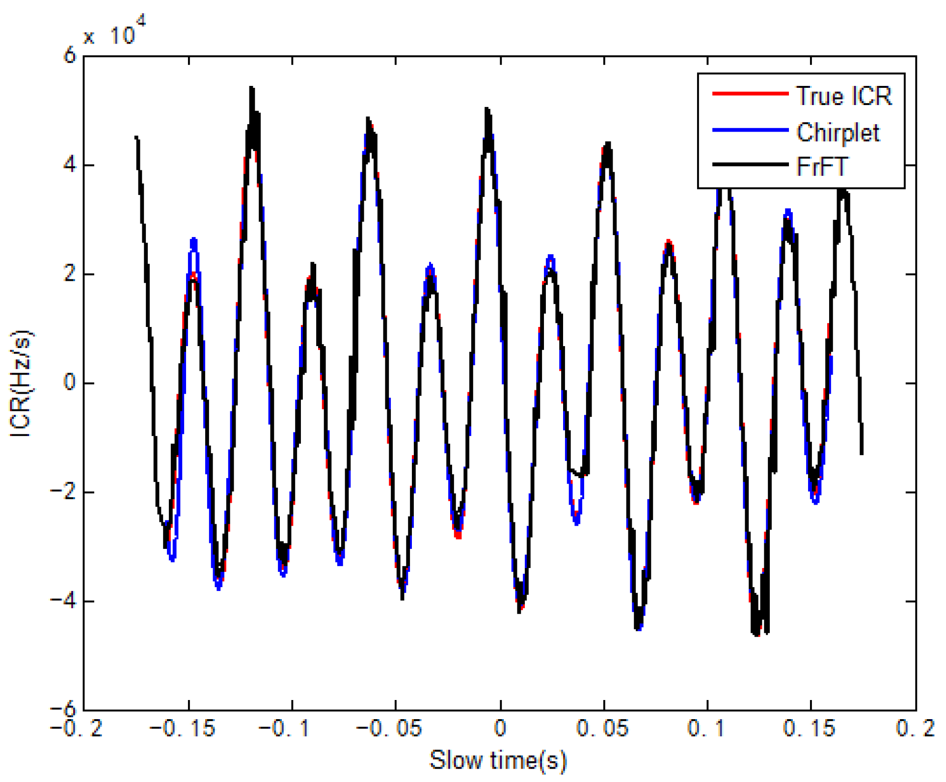
Step 2: Estimate the ICR of the signal with chirplet decomposition.
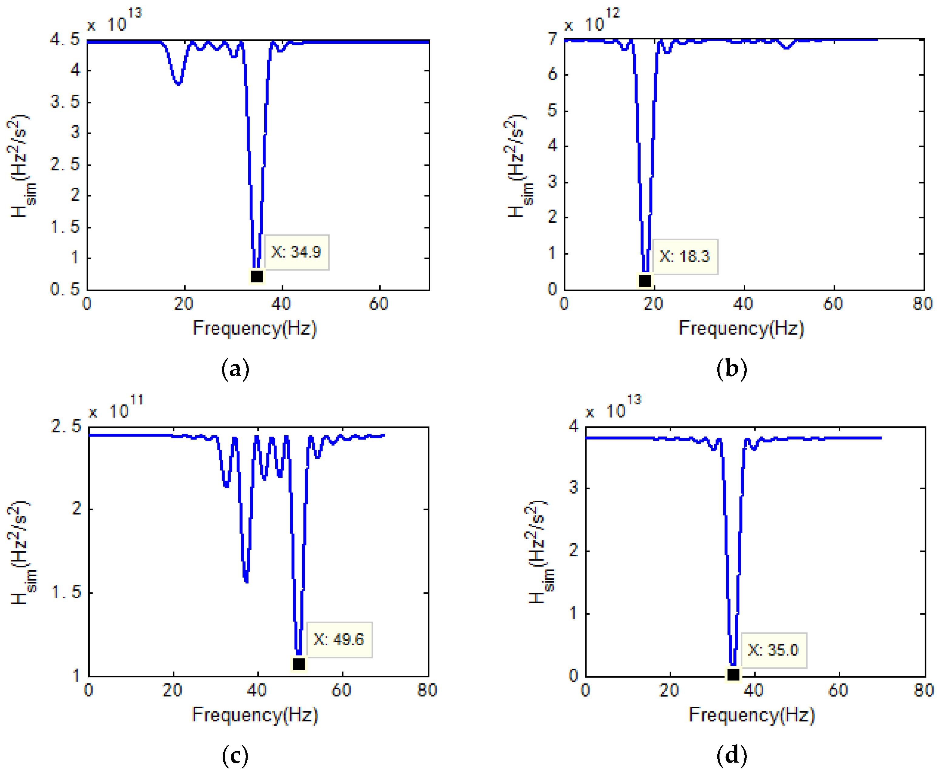
Step 3: Perform LS to estimate the frequency of the component with the largest amplitude in the current ICR, and further estimate the amplitude and initial phase corresponding to the frequency.
Step 4: Remove the estimated components in ICR.
Step 5: Calculate the threshold and compare it with the amplitude of the currently estimated vibration component. If the latter is larger, return to step 3. Otherwise, proceed to step 6.
Step 6: Calculate the corresponding to each vibration component according to the estimated parameters and perform LS to re-estimate the parameters.
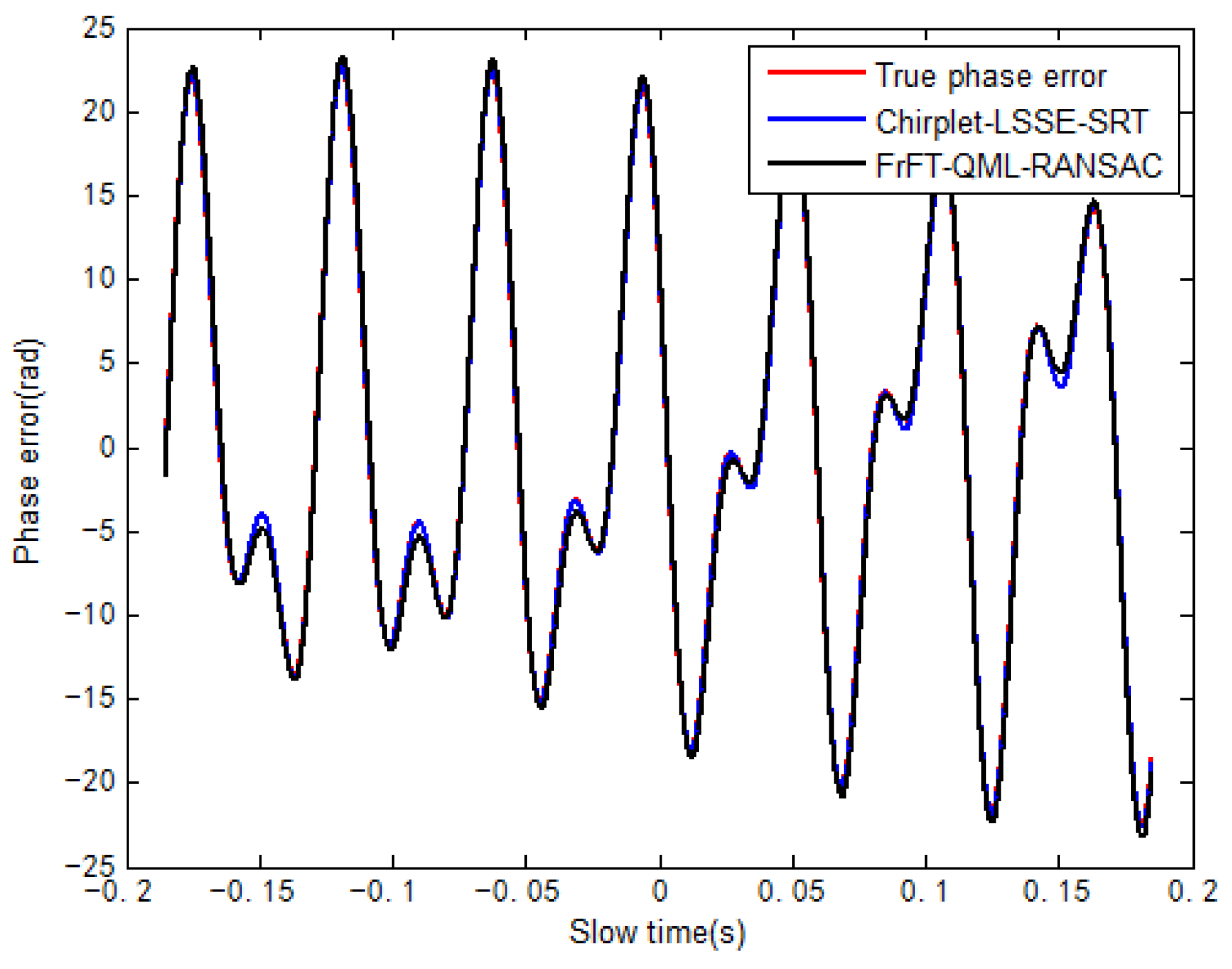
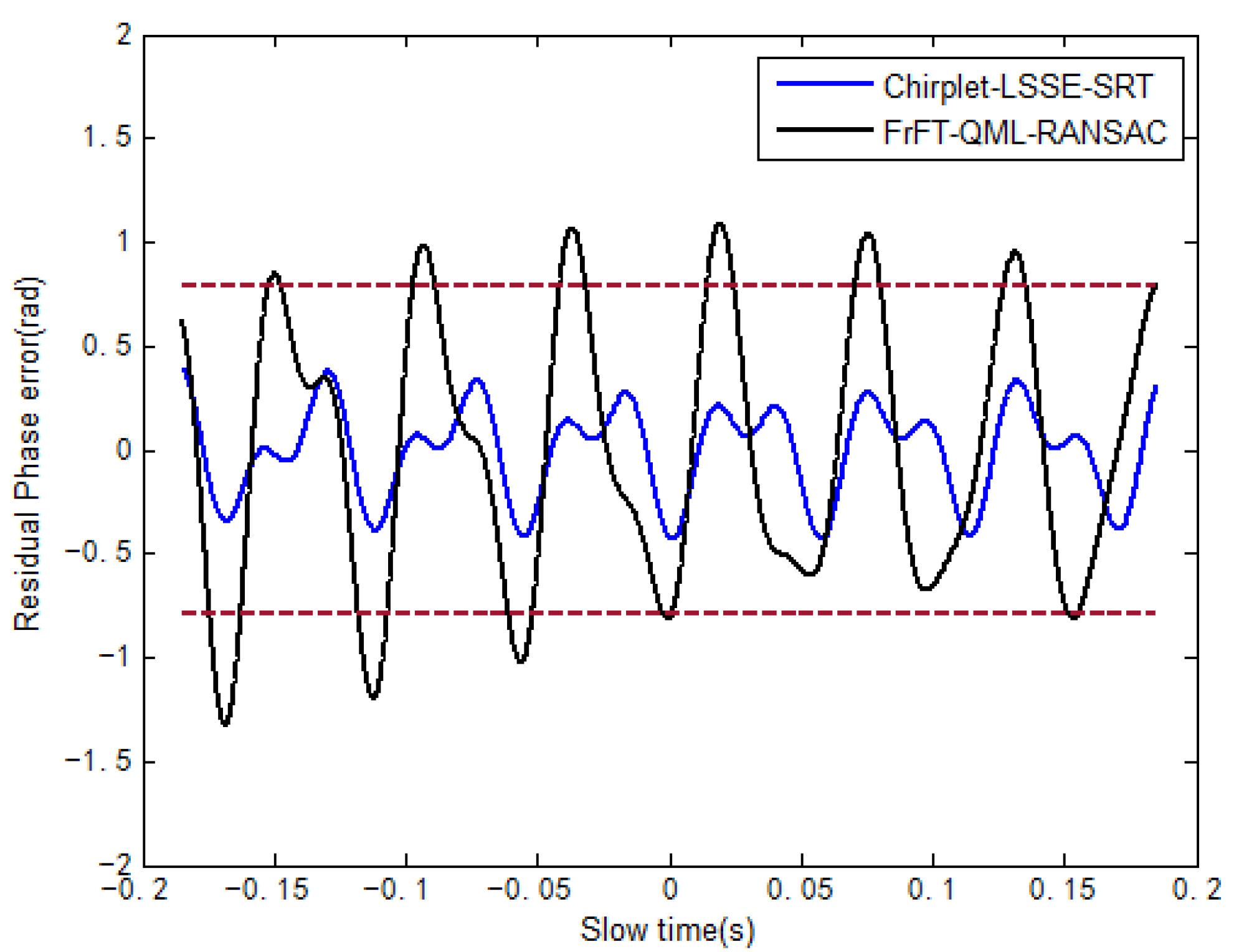
Figure 3 is the flow chart of proposed method. After estimating parameters of all components of high-frequency vibration, the phase error compensation function for the echo signal can be constructed as follows
After compensating the phase errors of high-frequency vibration, the focusing imaging can be completed by conventional imaging processing algorithms such as the range migration algorithm (RMA) [
7].


