1. Introduction
GRACE consists of two near-circular polar orbit satellites orbiting at an altitude of approximately 500 km in coplanar orbits, carrying a KBR (K-band ranging) instrument that measures inter-satellite range on the micron scale. However, in the recovery of the gravitational field, the required observation values are the inter-satellite range and range rate between the center of mass (CoM) of the satellite, so it is necessary to convert the range measurements between the KBR antenna phase center (APC) into the range observation values between the CoM of the satellite. Accurate satellite attitude and KBR APC coordinates are needed to ensure that the accuracy of range measurements is not lost during the conversion process.
The KBR APC vector of satellites relative to the CoM of satellites (CoM-to-APC [
1]) is generally accurately measured before it enters orbit. However, the accuracy of ground measurement is limited and affected by the measurement accuracy of the whole satellite structure. After the satellite enters orbit, both the satellite body and the APC are affected by stress release, platform vibration, and space temperature change, leading to changes in the CoM-to-APC vector [
2]. It is necessary to calibrate the CoM and KBR APC of the satellite periodically after the satellite is in orbit to obtain an accurate CoM-to-APC vector. JPL (Jet Propulsion Laboratory), the official agency of GRACE and GRACE-FO satellites, typically writes initial and calibrated CoM-to-APC vectors into Level-1B VKB1B products.
The CoM of the satellite can always coincide with the proof mass of the accelerometer by periodic CoM calibration and CoM-Trim (the Mass Trim Assembly Mechanism (MTM) on all three axes of the GRACE-type satellite is adjusted accordingly in order to realize the compensation of CoM offset; this is called a CoM-Trim event). Therefore, it is more advantageous to set the origin of the Science Reference Frame (SRF) at the proof mass of the accelerometer. VKB1B products in the SRF can be accurately determined by periodic KBR phase center calibration, which can be used for KBR Level-1A to Level-1B data processing. In order to ensure that the KBR APC error does not affect the accuracy of inter-satellite range and range rate, the CoM-to-APC vector determination accuracy should reach 0.3 mrad in the Y (pitch) and Z (yaw) directions [
3].
Although the determination accuracy of the mounting matrix of the star camera (QSA1B, rotation from star camera frames into the SRF), the estimation accuracy of the CoM (VCM1B, vector offset file for CoM solution from calibration maneuvers or tracking model in the SRF) of the satellite, and the realization accuracy of the inter-satellite pointing (QCP1B, rotation from the combined SCA “pilot” frame to the KBR pointing frame) will all have an impact on the KBR range measurement, this paper does not discuss the influence of the above three factors, and assumes that they all meet the accuracy requirements.
For the problem of KBR calibration, two maneuvering modes are proposed [
3], linear drift maneuvering and periodic oscillation maneuvering, for on-orbit calibration of the KBR APC. Inter-satellite range and inter-satellite range rate are used in the calculation, and polynomial fitting is adopted to eliminate the low-frequency residual errors of precision orbit determination (POD). However, phase deviation parameters need to be introduced when the inter-satellite range is used to estimate the KBR APC. In [
4], a nonlinear Kalman filter is used to estimate the KBR APC, and the simulated observation value does not consider the influence of orbit low-frequency error. The authors of [
5,
6] proposed the use of a predictive Kalman algorithm to estimate the star camera quaternion of the satellite, and the use of an extended Kalman filter algorithm to achieve the on-orbit calibration of the KBR APC. However, when the frequency of star camera observation data is high, the improvement of attitude estimation accuracy by the Kalman algorithm is not obvious, and the influence of orbit low-frequency error is not considered in this method.
To counteract the effects of residual low frequency errors and time-varying gravity fields, this paper proposes using the inter-satellite range acceleration as the observation value to obtain a high precision KBR APC estimation result. At the same time, the inter-satellite range and the inter-satellite range rate are taken as the observation values, and polynomial fitting is carried out. The KBR APC calibration is calculated with three observation values at the same time, and the result with higher estimation accuracy is selected as the final KBR APC calibration result. In view of the parameter estimation algorithm, this paper proposes using the M-estimation (robust estimation) method [
7,
8]. Through an IGGG-3 weighting scheme [
9,
10], the influence brought by the gross error of observation value and the gross error of design matrix can be overcome.
2. KBR Calibration Maneuver Scheme of a GRACE-Type Gravity Satellite
Due to its complexity, an analytical solution for the determination of the KBR APC can only be given under quite a number of restrictions. Therefore, experimental methods are generally used to determine the APC. In the ground stage, the calibration of the KBR APC is achieved by the method of one phase center swinging with certain regularity relative to another phase center [
3].
This concept is based on rotating the satellite back and forth along a certain axis: the KBR antenna generates maneuvering signals with the satellite and the KBR APC reference point is found at the location of the observed minimum change in generating phase response [
3]. However, only maneuvers in the direction perpendicular to the inter-satellite pointing (pitch axis (Y), yaw axis (Z)) can generate the sensitive inter-satellite ranging signal, and the maneuvers in the rotation axis (X) will not generate the ranging signal. In order to generate strong signals, the offset angle is generally set in advance, and then the satellite is shaken with a certain amplitude and period, because the ranging signal variation caused by the attitude maneuver of the satellite increases with the increase of the offset angle [
3].
The KBR calibration of GRACE and GRACE-FO satellites adopted the calibration maneuver scheme proposed by Wang [
3]. Using the satellite sequence of events (SOE) files recorded by JPL, the dates of KBR calibration and calibration events of GRACE-FO and GRACE are listed in
Table 1 and
Table 2.
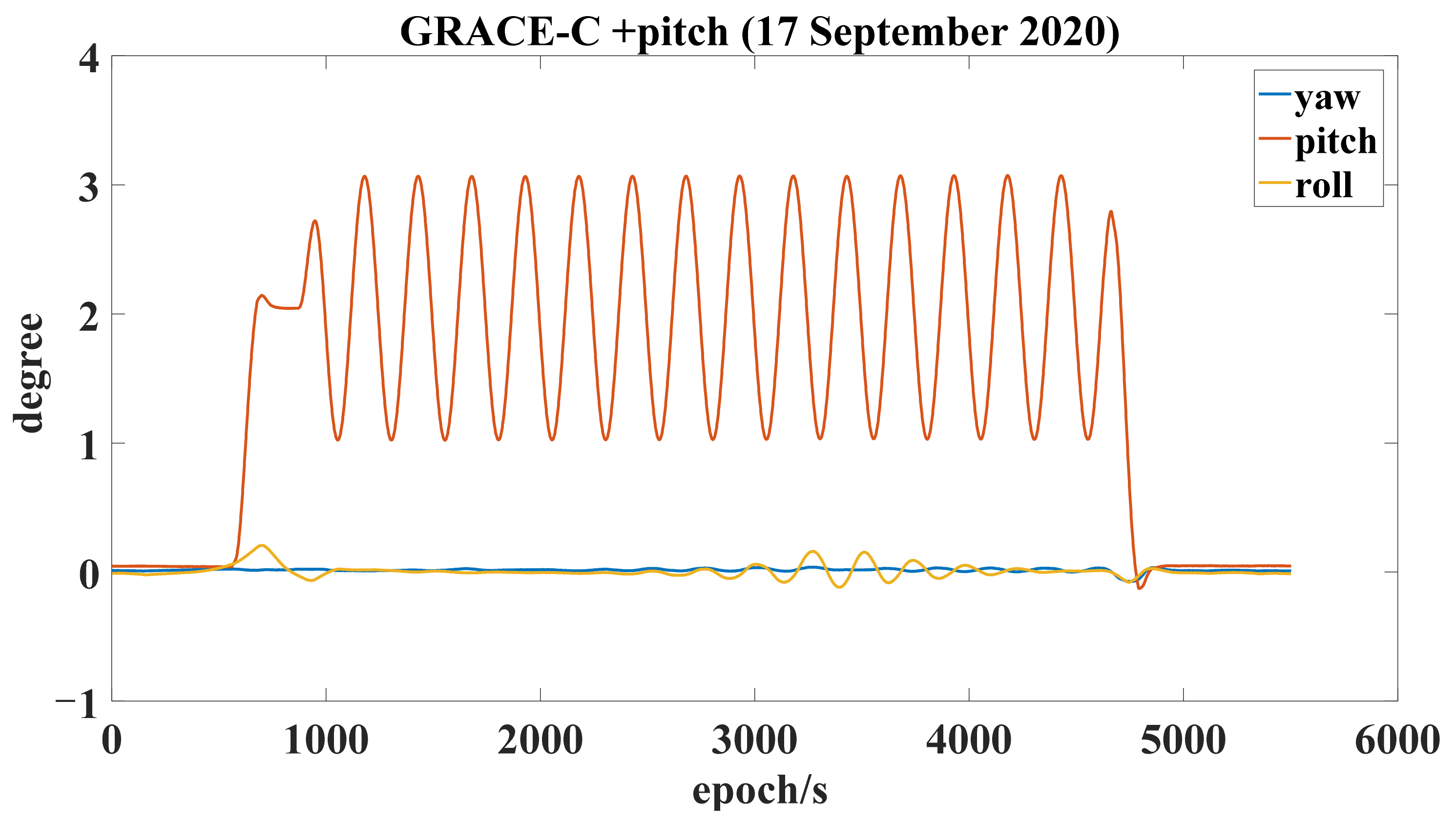
Taking the KBR calibration maneuver of GRACE-C on 17 September 2020 and GRACE-D on 28 September 2020 as an example, four sub-maneuvers were carried out for each satellite, respectively: + pitch, −pitch, +yaw, and −yaw, where “+” means that the satellite offset angle is +2 degrees and “−” means that the satellite offset angle is −2 degrees. After setting the offset angle of 2 degrees, a sinusoidal maneuver signal with a period of 250 s and an amplitude of 1 degree is applied to the satellite, which generally lasts for 15 cycles with a total of 3750 s. The maneuver execution time required to achieve offset angle and return to normal inter-satellite pointing is about 30 s, and the total maneuver time is 3780 s.
Figure 1 shows the inter-satellite pointing angle of GRACE-C during a single +pitch maneuver.
On-orbit calibration maneuvers of KBR are performed by a magnetorquer (MTQ) and ACTs (attitude control thrusters) of an attitude and orbit control system (AOCS). The subsystem of attitude and orbit control automatically calculates the required rotation torque, that is, the combination of the rotation torque of the attitude control thrusters and MTQ is used to drive the satellite to complete the designed attitude maneuver.
The inter-satellite pointing angle of GRACE and GRACE-FO during KBR calibration was calculated [
11]. The intersatellite pointing angle comprises
and
in Figure 6, which represent the satellite KBR Frame (KF, K-Band Frame) and the line between the centers of mass of the satellites (LOSF, Line-of-Sight Frame).
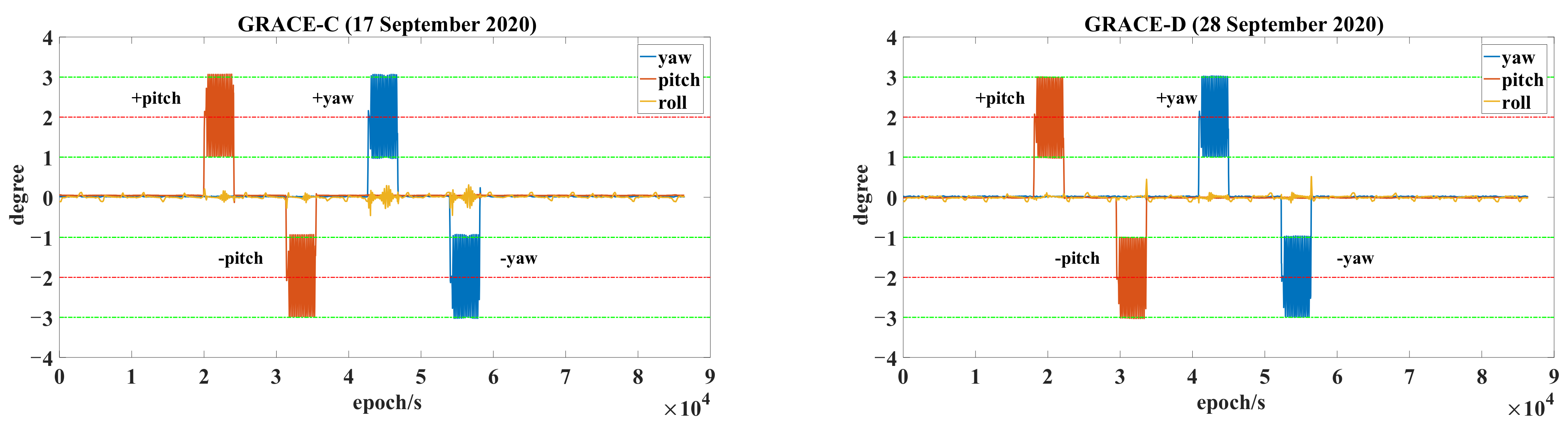
Figure 2 shows the inter-satellite pointing angles of GRACE-C and GRACE-D.
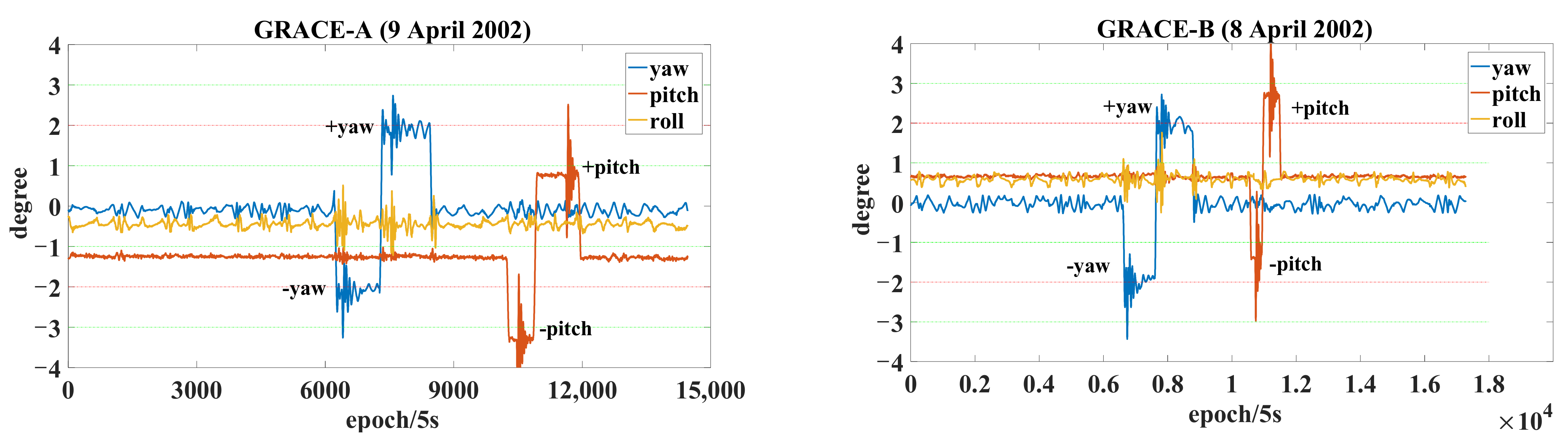
In this paper, the inter-satellite pointing angles of the GRACE satellites during the KBR calibration period (except the time when Level-1B observation data were missing) were calculated, respectively. As can be seen from
Figure 3, the maneuver strategy determined by GRACE in 2002 was not clear, and there is about 1 degree deviation in the pitch and roll directions; the author speculated that the maneuver strategy was explored and improved (implemented by AOCS) after this unqualified sub-maneuver.
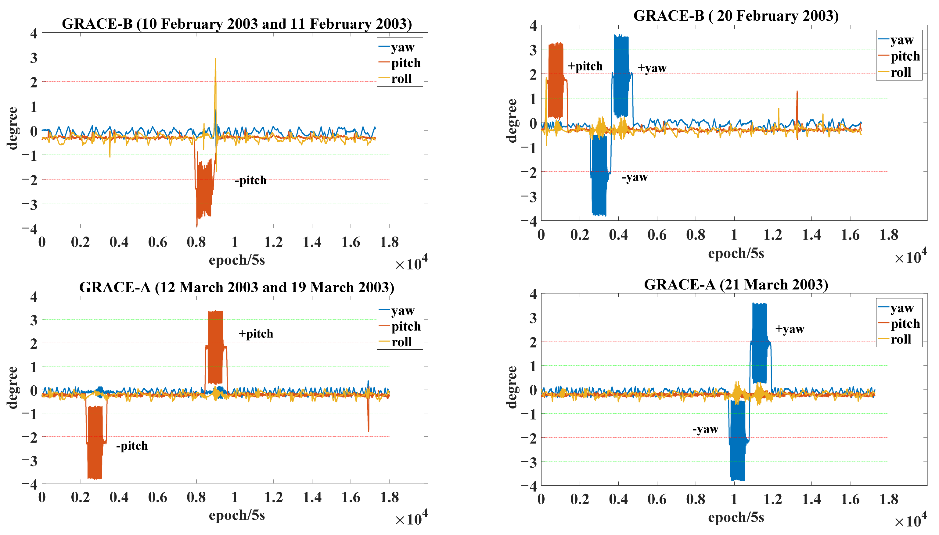
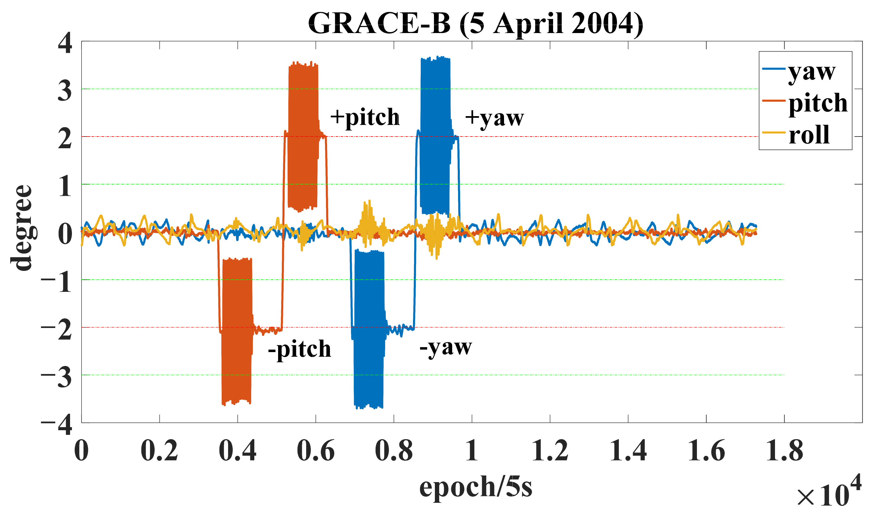
As can be seen from
Figure 4 and
Figure 5, it adopted a maneuver strategy consistent with that of the in-orbit GRACE-FO satellite in
Figure 2. However, its maneuver amplitude in the pitch direction reached about 1.5 degrees and its maneuver amplitude in the yaw direction reached about 1.7 degrees, while the amplitude of GRACE-FO in the KBR calibration maneuver was 1 degree.
The potential multipath effect of the KBR ranging signal can be reduced by using a positive and negative maneuver as mirror maneuvers of each other. When the mirror maneuver is not included, the KBR calibration of GRACE-FO contains the following four sub-maneuver signals.
Sub-maneuver 1: The following signal
around the pitch axis (Y) is applied to GRACE-C, where superscript 1 represents GRACE-C, superscript 2 represents GRACE-D,
represents constant deviation angle,
represents the angular amplitude of the periodic signal, and
represents the frequency of the periodic signal. The maneuver signal is expressed as
During the pitch maneuver of GRACE-C, the GRACE-C deviation from the nominal roll and yaw angle should be kept as small as possible, and GRACE-D must maintain its nominal attitude. In this case, the KBR ranging measurements are highly sensitive to the CoM-to-APC vector of the Z and X direction of GRACE-C. Therefore, a single GRACE-C pitch maneuver can calculate the CoM-to-APC vector in the Z and X directions of GRACE-C. However, due to the higher signal-to-noise ratio in the Z direction than in the X direction, the accuracy of the estimated Z direction APC vector is better than that in the X direction. When the KBR range value is converted to the range of the CoM of the satellite, the KBR APC estimation error in the X direction of the two satellites is absorbed by the constant phase deviation of the KBR ranging measurements, which does not affect the gravity field reversion accuracy.
Sub-maneuver 2: The following signal
about yaw axis (Z) is applied to GRACE-C, and other parameters have the same meaning as sub-maneuver 1.
Sub-maneuver 3: The following signal
about pitch axis (Y) is applied to GRACE-D, and other parameters have the same meaning as sub-maneuver 1.
Sub-maneuver 4: The following signal
about yaw axis (Z) is applied to GRACE-D, and other parameters have the same meaning as sub-maneuver 1.
3. Estimation Algorithm of the KBR APC
The position vectors of the satellite in the inertial system are, respectively,
and
, the rotation matrix transformed from the SRF to the inertial system is
and
, and the vector between the CoM of the satellite [
12] is
The distance between the CoM of the satellites is
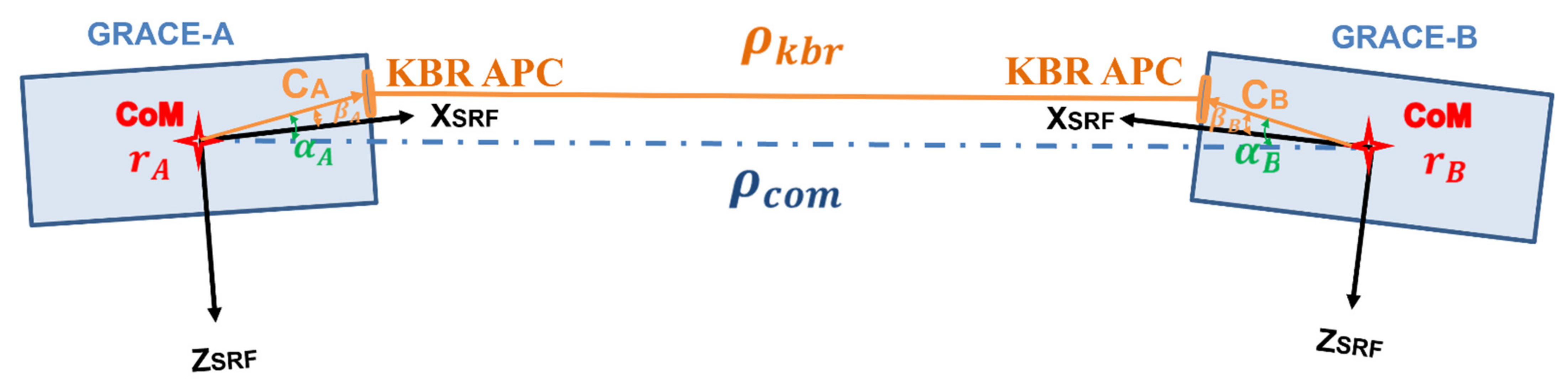
However, KBR observes the range between the KBR APC, as shown in
Figure 6. Through vector conversion, the KBR observation range can be expressed as
where
is the corrected KBR APC vector (CoM-to-APC) in the SRF. More succinctly, it can be expressed as
Approximately, the KBR range measurements can be expressed as the distance between the CoM of GRACE-A and GRACE-B minus the APC correction (that is, the projected distance of the APC vectors of the two satellites in the LOSF (the line between
and
)):
and
can be expressed as
where
is the unit vector of the satellite CoM LOSF (Line-of-Sight Frame) obtained by
Then, the observation equation of KBR calibration is obtained by
where
is the design matrix,
is the estimated value of the KBR APC and the phase deviation term to be obtained, and
contains maneuver signals applied during KBR calibration, but it contains a large low-frequency error. Firstly, the error of orbit 1 cycle per revolution (cpr) contained in
and
cannot be completely offset; secondly, the inter-satellite ranging signal in
measures the current gravity field signal, while the gravity signal contained in
(the difference of the reduced dynamic orbit) is greatly affected by the prior gravity field. Therefore, the residual effect of the low frequency error will still exist after the minus:
. Polynomial fitting is considered to remove its influence first, and then KBR APC parameters are estimated to avoid excessive parameters caused by estimating polynomial parameters and KBR APC parameters at the same time.
When the difference of the satellite velocity is
, the velocity between the CoM of the satellite can be expressed as
When the difference of the satellite accelerations is
, then the acceleration between the CoM of the satellite can be expressed as
Then, the inter-satellite range rate measured by KBR can be expressed as
The observation equation of KBR calibration based on inter-satellite range rate is
where
represents the partial derivative matrix of the polynomial; the third-order polynomial is used in this paper.
The inter-satellite range acceleration measured by KBR can be expressed as
The KBR calibration observation equation based on inter-satellite range acceleration is
Observation Equations (13), (17), and (19) are constructed according to the above equation, and the estimated KBR APC values of the two satellites can be calculated according to the three observation values based on the LS estimation and M-estimation.
In the LS estimation and the initial weighting of the M-estimation, the weight matrix of the observed value is taken as the identity matrix in this paper. When constructing the observed values of inter-satellite range, range rate, and range acceleration, only light time correction term is carried out.
4. KBR Calibration Results of GRACE-Type Gravity Satellites
The RL04 version Level-1B GNI1B, SCA1B, and KBR1B data during the KBR calibration period of the GRACE-FO satellite were downloaded from
ftp://isdcftp.gfz-potsdam.de on 5 April 2022 [
13], and their meanings are shown in
Table 3. At the same time, the RL02 version GNV1B, SCA1B, and KBR1B data of GRACE satellites during the KBR calibration stage were downloaded [
14]. The data sampling rate was 5 s, and the data meaning is similar to that in
Table 3.
4.1. Low Frequency Error Processing
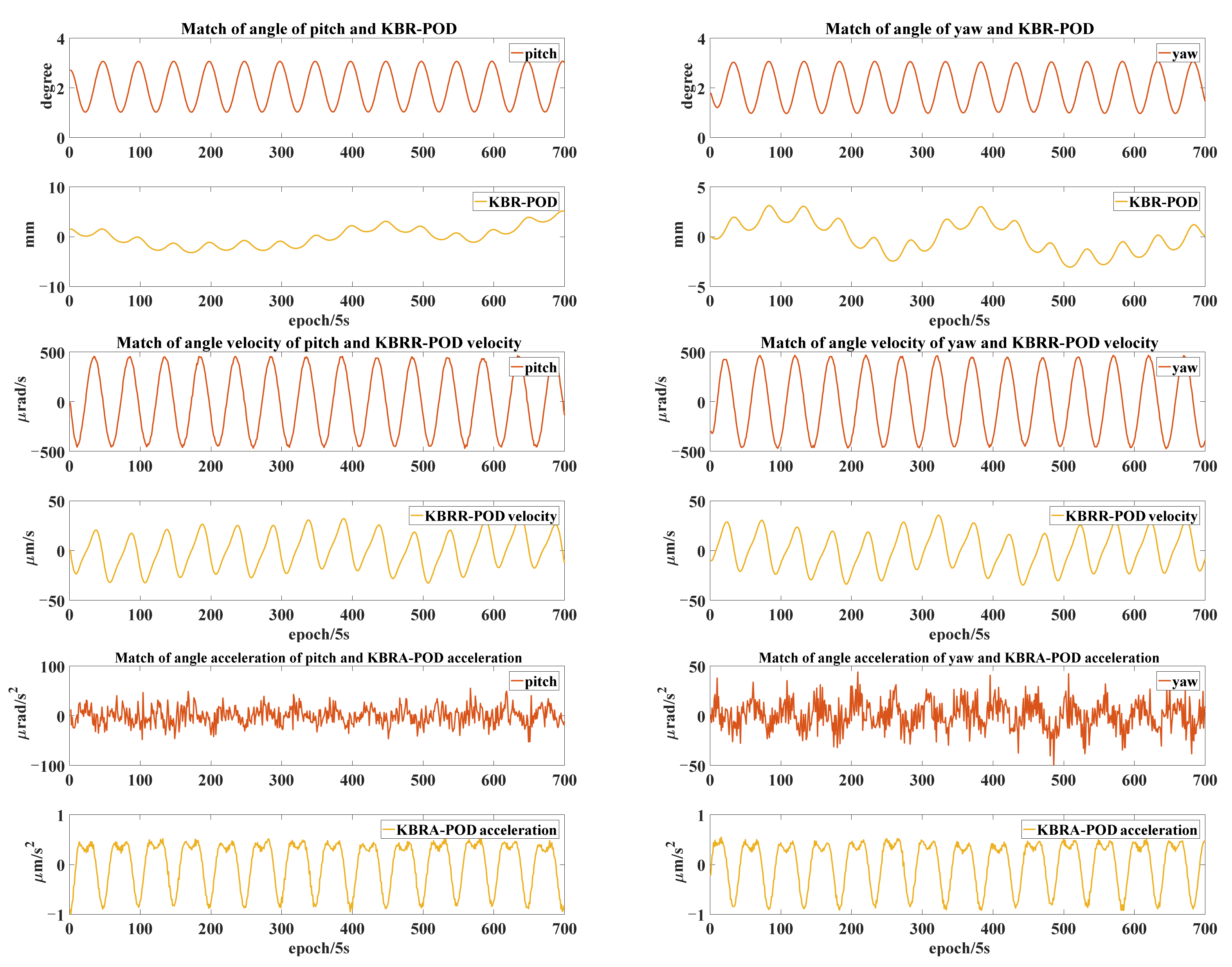
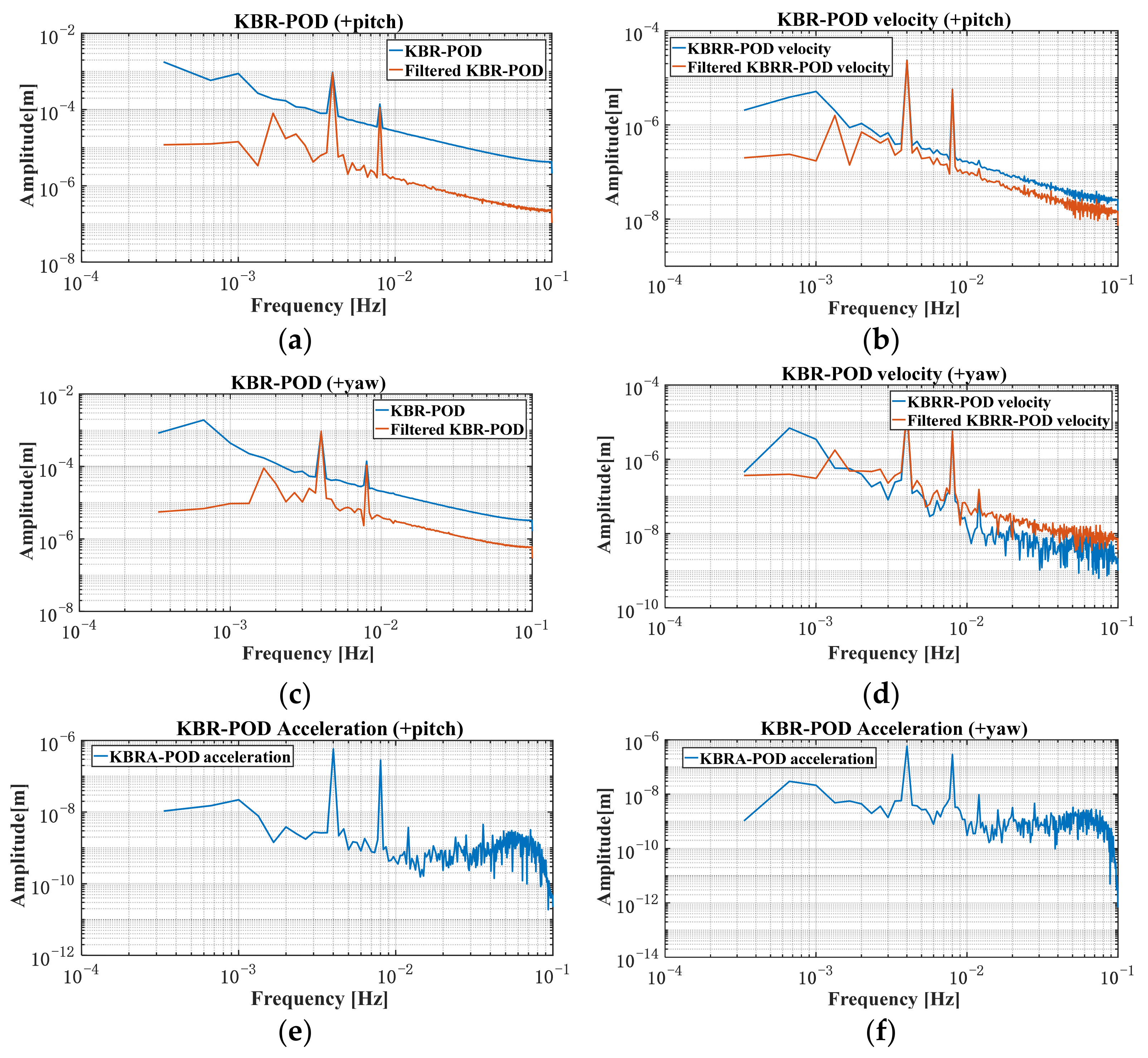
In a single maneuver, 700 epochs were selected in total for calculation. In order to avoid the influence of large maneuvers, 125 s before and after maneuvers were removed. Firstly, the inter-satellite pointing angle, angular velocity, and angular acceleration of +pitch maneuver and +yaw maneuver of GRACE-C were calculated. The corresponding KBR ranging value (KBR), range rate (KBRR), and range acceleration (KBRA) were calculated and taken as the observed value (O). Then, the inter-satellite baseline, baseline rate, and baseline acceleration determined by POD (precision orbit determination) were taken as the calculated values (C), and the differences between the KBR measurements (O) and the inter-satellite baseline (C) was obtained (O−C): represented as “KBR-POD”, “KBRR-POD velocity”, and “KBRA-POD acceleration”, respectively.
As can be seen from
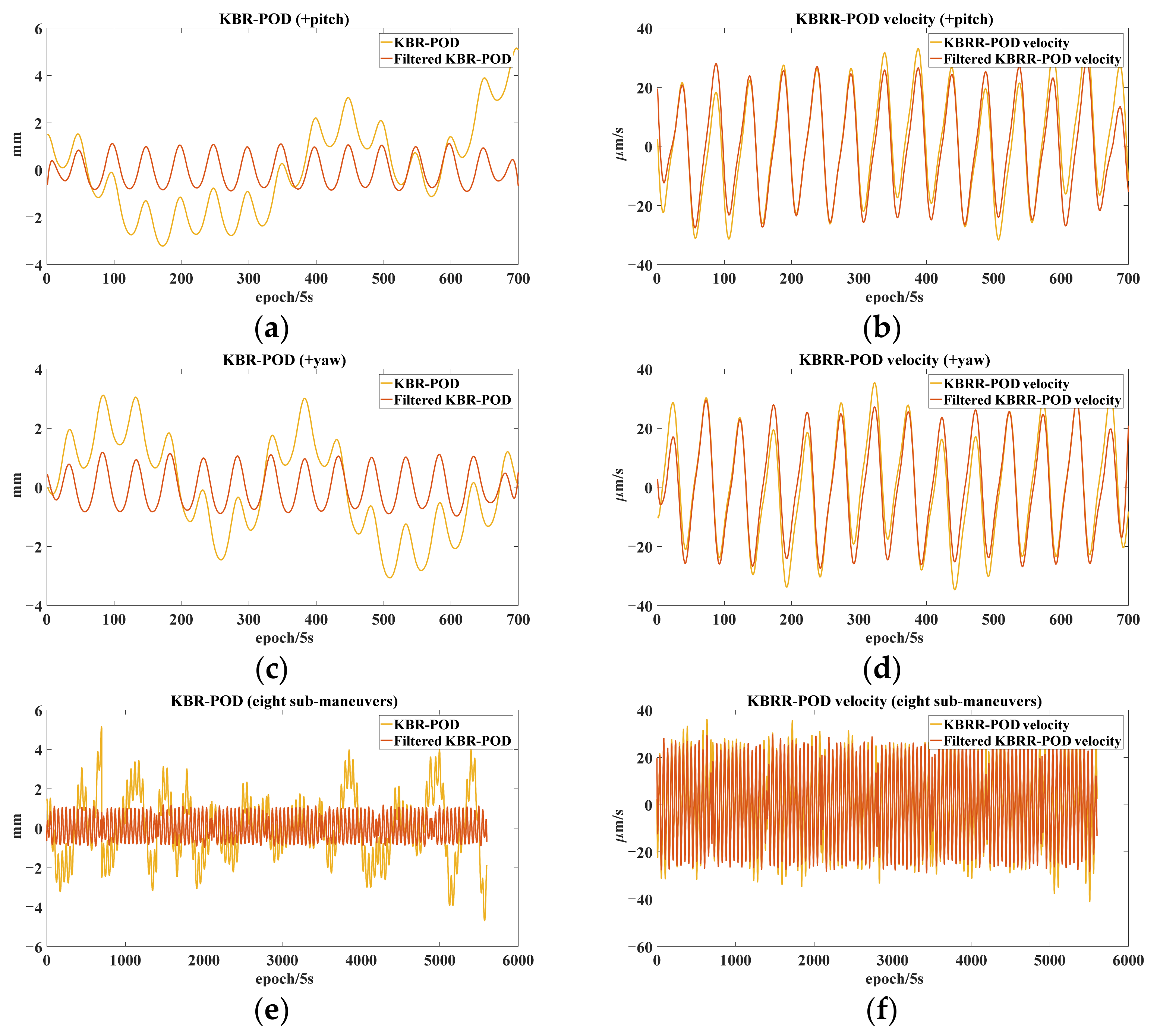
Figure 7, O−C has a good consistency with the applied pitch and yaw maneuver signals. However, the “KBRA-POD acceleration” contains significant high-frequency noise, which may affect the estimation accuracy of KBR APC. “KBR-POD” and “KBRR-POD velocity” still contain low-frequency periodic signals, which need to be fitted. In this paper, the 15-order and 13-order polynomial fitting is carried out, respectively, and the filtered results (after removing the best fitting polynomials) are obtained in
Figure 8, where
Figure 8a–d are the results of polynomial fitting on the single +pitch, +yaw maneuver data of GRACE-C and
Figure 8e,f are the filtering results of observation values of “KBR-POD” and “KBRR-POD velocity” obtained after polynomial fitting on all the KBR calibration data of eight sub-maneuvers. As can be seen from
Figure 8a–f, the low frequency errors were effectively removed.
For the three kinds of observation values, the first and last 50 s observation values were removed, and then Fourier transform was carried out. The polynomial fitting effect was analyzed in terms of frequency, as shown in
Figure 9a–d, corresponding to
Figure 8a–d. The maneuvering frequency signal of 40 mHz and twice the maneuvering frequency signal of 80 mHz were retained, and the low-frequency noise was effectively suppressed. While, as shown in
Figure 8d, higher amplitudes can be seen for the filtered results for nearly all frequencies above 1 mHz, this may be due to errors from the polynomial fitting. As shown in
Figure 9e,f, analyzing the “KBRR-POD acceleration” observation value from the frequency domain, the polynomial fitting is not required and the low-frequency noise interference is small.
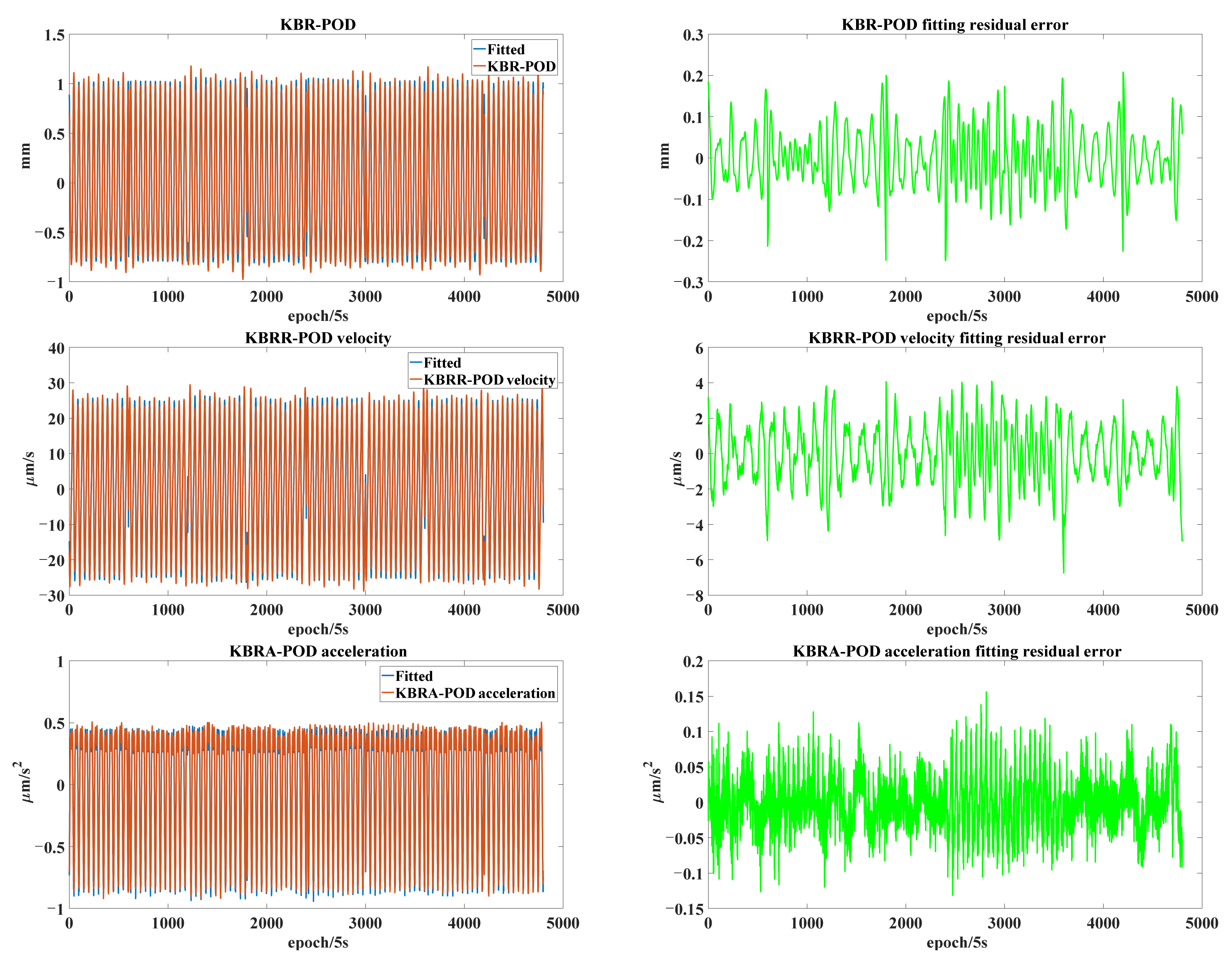
4.2. KBR APC Estimation Based on LS Estimation and M-Estimation
The filtered observation values of “KBR-POD” and “KBRR-POD velocity” and the unfiltered observation values of “KBRA-POD acceleration” were used to estimate the vector (CoM-to-APC) of KBR APC in the SRF, corresponding to the angle
and
in
Figure 6. The least squares fitting curves and fitting residual results by the three estimation methods were obtained. It can be seen from
Figure 10 that all the three methods can achieve good fitting effects. In this calculation, we stripped out the observations of 50 epochs at the beginning and the end, and combined the data of four sub-maneuvers and four mirror sub-maneuvers.
The GRACE-C and GRACE-D APC vectors estimated by the three observation values obtained from the eight sub-maneuvers were denoted as X
APC, Y
APC, and Z
APC, respectively, and the formal errors were calculated according to the least squares accuracy estimation theory. As can be seen from
Table 4, Y
APC and Z
APC estimated by “KBR-POD” had high accuracy. However, due to the need to solve the phase deviation term (Bias) of the ranging value, the accuracy of the estimated X
APC and phase deviation term was low. The reason is that the collinearity of X
APC and the phase deviation term leads to the ill-conditioned normal equation, which indirectly leads to the unreliable estimated Y
APC and Z
APC, and the results are deviated by the other two estimation methods. The X
APC estimated by “KBRA-POD acceleration” had a high accuracy, and the calibration result obtained by “KBRA-POD acceleration” was selected as the final KBR calibration result in this paper. Among them, the LS estimation accuracy of Y
APC and Z
APC was about 138 μm, about 0.096 mrad, which meets the index of 0.3 mrad. The LS estimation accuracy of X
APC was 2.4 mm.
In order to verify the effectiveness of the mirror maneuver, the paper only uses the positive maneuver and mirror maneuver for KBR APC calibration data, respectively, to obtain the calibration results. The results are shown in
Table 5. The Y
APC and Z
APC values are obviously large, and the estimation accuracy (formal error) does not meet the accuracy requirements of 0.3 mrad. The results show that the KBR calibration results are easily affected by multipath error when the mirror maneuver is not adopted, which leads to the inaccurate KBR APC estimation results. According to the positive and negative sign characteristics of Y
APC and Z
APC calibrated values in the calibration results, they are just opposite, which is the reason why correct results can be obtained by combining positive and negative maneuvers.
Since the observed values may still contain gross errors, in order to further improve the estimation accuracy, this paper uses the method of M-estimation to estimate the KBR APC, combining the data of four positive maneuvers and four mirror maneuvers. The estimation results are shown in
Table 6. The KBR APC accuracy estimated by the three observation values was greatly improved. Among them, the estimation accuracy of the proposed inter-satellite range acceleration estimation in the Y and Z directions was improved from 138 μm to 72 μm, and the X direction was improved from 2.5 mm to 1.3 mm, with an increase of nearly 50%.
VKB1B results of GRACE-FO recommended by this paper obtained from M-estimates are shown in
Table 7, while the SOE file gives GRACE-FO VKB1B in May 2019, indicating a significant change in the Z
APC of GRACE-D. The authors recommend that this change be taken into account during KBR data preprocessing.
At the same time, the VKB1B of GRACE recommended by this paper (in 2004, GRACE-A did not perform the KBR calibration maneuver, so the APC of GRACE-A could not be estimated) was calculated by using the method of M-estimation, and VKB1B results calculated by JPL recorded in SOE files are shown in
Table 8. The results of the Y and Z directions estimated in this paper are close to those of JPL’s solution, which shows that the KBR calibration algorithm proposed in this paper is feasible.
5. Discussion
The above maneuver strategy can be used to estimate the KBR APC of GRACE-type satellites. Although any other maneuvers can also be used for KBR calibration (as shown in
Figure 3 or the linear drift maneuver method), the sinusoidal maneuver strategy is a more reliable KBR calibration maneuver scheme. The positive maneuver and negative maneuver (mirror maneuver) mode is very important for KBR calibration and can effectively eliminate the multipath influence of the KBR ranging signal. The results of KBR calibration with combined positive and negative maneuvers are reasonable and accurate.
In estimating the KBR APC, we can choose the strategy of using CoM-to-APC in the fixed X direction as the known value and only solving the Y and Z direction APC. In fact, when the APC vectors of three directions are solved simultaneously, the accuracy of the X direction is the worst. Therefore, the APC of the X direction is generally not updated, but the measured value of the ground is used. In addition, the APC vectors of the Y and Z direction obtained by the two strategies (fixed X direction or not) are consistent. Therefore, the APC vectors of the three directions were solved at the same time in this paper, but the APC vector of the X direction was not recommended.
Although the application of “KBRA-POD acceleration” as the observation value can effectively eliminate the influence of low-frequency error, it amplifies the influence of high-frequency noise, and there is no effect method to eliminate the high-frequency noise contained in the observation value and the design matrix at the same time. In fact, as shown in
Figure 7, better accuracy can be obtained by using “KBRA-POD acceleration” as an observation value to estimate the CoM-to-APC if the maneuvering strategy implemented by the attitude and orbit control system results in smoother angular acceleration. By calculating the CoM-to-APC of the three observation values at the same time, the results can be better verified and the estimated results with better integrity can be obtained. In the estimation of GRACE satellite APC, due to the ill-posed problem of the normal equation, the solution results deviated from the results of the other two algorithms. Finally, the solution results obtained by “KBRR-POD velocity” observation values with higher accuracy were adopted. “KBR-POD” is not recommended for subsequent calculation.
Compared with the least squares estimation method, the improved accuracy of the M-estimation method is obvious. The reason is that there may still be gross error or high frequency error in the observed value and design matrix, and the weight of these observed value can be reduced by using M-estimation. Because the weight matrix of the observed value is taken as the identity matrix in this paper, other weighted least squares strategies can also resist gross errors and improve accuracy, which is worth further study.
6. Conclusions
This paper summarized the KBR calibration algorithm of GRACE-type gravity satellites, proposed estimating the APC of KBR using inter-satellite range, range rate, and range acceleration simultaneously, and verified the KBR calibration results based on three kinds of Level-1B observation data of GRACE and GRACE-FO. The results show that the APC of KBR obtained by LS estimation using “KBRA-POD acceleration” was 138 μm in the Y and Z directions, and 2.5 mm in the X direction. When M-estimation was used, the accuracy was 72 μm in the Y and Z directions and 1.3 mm in the X direction. In this paper, KBR calibration calculation was performed on the data of positive and mirror (negative) maneuvers. It was shown that the mirror maneuver is required for the KBR calibration of GRACE-type gravity satellites in order to obtain the APC estimation results that meet the accuracy requirements.
In this paper, positive and mirror (negative) maneuvers are recommended for KBR calibration. During KBR calibration, range rate and range acceleration can be used as observation values to estimate the KBR APC, and the optimal solution results are selected as the final VKB1B recommended value. M-estimation is recommended for parameter estimation.


