Abstract
Due to the short revisit time and large coverage of Geosynchronous synthetic aperture radars (GEO SARs) and the increasing number of low earth orbit synthetic aperture radar (LEO SAR) constellations, radio frequency interference (RFI) between GEO SARs and LEO SARs may occur, deteriorating the quality of SAR images. Traditional methods only simplify RFI to noise-like interference without considering the signal characteristics. In this paper, to accurately evaluate the impacts of GEO-to-LEO RFI and LEO-to-GEO RFI on imaging quantitatively, an RFI-impact quantitative analysis model is established. Taking account of the chirp signal form of SAR systems, the RFI power and image Signal-to-Interference-plus-Noise Ratio (SINR) are theoretically deduced and validated by numerical experiments. Based on the proposed method, the SAR image quality under different system parameters and bistatic configurations is estimated, and the probability of different configurations is also given. The results show that specular bistatic scattering RFI between GEO SARs and LEO SARs has serious effects on imaging, and the probability can approach 2% for certain orbital parameters and will become higher as LEO SAR constellations increase in the future, implying the necessity to suppress the RFI between the GEO SAR and the LEO SAR system.
1. Introduction
Synthetic aperture radars (SAR) have been widely used in Earth remote sensing, which can provide images with high resolution and wide swath under day-and-night conditions [1,2], having an important role in disaster monitoring [3,4]. However, SAR systems may be exposed to other non-coherent electromagnetic signals with the same or adjacent signal frequencies, called radio frequency interference (RFI) [5]. Taking an L-band SAR as an example, it may be affected by devices working in the same or adjacent frequency bands such as television, radio and communication equipment [6], radio navigation systems, early warning radars, wind profile radars, etc. [7,8,9]. Moreover, devices working in different frequency bands may also cause interference through harmonics [10].
RFI has been observed in current SAR systems, such as L-band JERS-1 [11], ALOS PALSAR [12,13], C-band Sentinel-1A [14,15] and X-band Terra-SAR-X [16,17]. RFI usually affects the image contrast (causing image blur) [5,18,19,20], changing the polarization characteristics [5,21] and introducing interferometric phase error to an interferometric SAR (InSAR) system [22,23]. Therefore, studies on RFI are important for improving the performance of SAR systems in complex electromagnetic environments [13,24,25,26].
Geosynchronous (GEO) SAR has great advantages such as large coverage and a short revisit time, providing rapid response and continuous observation of disaster areas [27,28,29,30,31]. However, due to its large coverage, GEO SARs are prone to observing the same area as low earth orbit (LEO) SARs simultaneously, potentially resulting in strong main lobe coupling between the two systems. As a result, GEO SAR signals can be received by a LEO SAR. Similarly, LEO SAR signals may be received by a GEO SAR, deteriorating SAR images if they have the same signal frequency. Furthermore, the large coverage and short revisit time of GEO SARs may increase the probability of RFI with LEO SARs.
Few studies have been carried out on the RFI between GEO SARs and LEO SARs. Monti-Guarnieri et al. discussed image Signal-to-Interference-plus-Noise Ratio (SINR) and transmission power requirement in the case of specular scattering and non-specular scattering, respectively. Moreover, they proposed a statistical model to evaluate the average of the RFI that GEO SARs receive from 30 X-band LEO SARs [32,33]. However, these studies did not consider the transmitted signal form of RFI sources and believed that RFI, with the overlap of GEO SAR and LEO SAR beams, would perform as noise and raise the noise floor. In fact, the RFI with chirp signal form could also obtain certain gain in SAR processing (although it would be small). In addition, according to the SAR geometry, only part of the overlap of the LEO SAR and GEO SAR beams can affect the single pixel SINR instead of the entire overlap. Furthermore, there are only a few studies on the impact of GEO-to-LEO RFI other than our previous work [34]. Therefore, based on [34], we make further efforts to evaluate the impact of RFI between GEO SARs and LEO SARs on imaging in this paper. Since SINR is an important indicator for measuring the image quality, an accurate image SINR in the presence of RFI was deduced.
To obtain the image SINR, the signal power and RFI power was calculated. The signal power was easy to obtain via radar equations, but there were two problems in the calculation of RFI power: (1) the RFI power given by the bistatic radar equation represented the energy scattered by a single resolution cell, but in fact, RFI defocused in SAR processing and generated an interference zone. As a result, the single resolution cell was affected by the area we were interested in containing an abundance of resolution cells. (2) It is generally believed that RFI has no gains in SAR processing. However, chirp signals can obtain some gains when mismatch occurs. The two issues are not mentioned in current research on RFI, which is the gap this paper strives to fill.
Furthermore, the degree of RFI influence depends on the observation geometry. Different geometric configurations cause different bistatic scattering coefficients due to the complex geometry of spaceborne SARs. For example, the bistatic scattering coefficient in the case of specular scattering is much higher than that in the case of non-specular scattering. As a result, the dynamic range of SINR is large and the level of impact is various. Therefore, the SINR in different configurations and the corresponding probability should be assessed, helping to avoid RFI impacts on SAR images by optimizing the orbital design of spaceborne SARs.
We focus on the impacts of RFI between GEO SARs and LEO SARs with the same center frequency on imaging. Considering the chirp signal form and the azimuth spectrum aliasing caused by different PRF of SAR systems, a RFI impact quantitative analysis model was established. Furthermore, the image SINR in the present of RFI was theoretically deduced and verified by experiments. Based on the theoretical analysis, the SAR image SINR for different system parameters, bistatic configurations and the corresponding probability are given.
This paper is organized as follows. In Section 2, the gain obtained by RFI in SAR processing is derived, then the receiving aperture area is analyzed, and an accurate image SINR calculation method is proposed. In Section 3, the method is verified by computer simulations, and the SINR with different pulse widths, bandwidths and bistatic configurations is given. In Section 4, a method for calculating the probability of different configurations is proposed, and the probability of specular scattering for different constellation elements is given. In Section 5, the final conclusions are drawn.
2. Accurate Modeling of SINR in the Presence of RFI
2.1. RFI Impact Quantitative Analysis Model
A sketch map of when a GEO SAR and a LEO SAR observe the same target is shown in Figure 1. O represents the position of the target, illuminated by a LEO SAR and a GEO SAR at the same time, L is the position of the LEO SAR, OL is the slant range of the LEO SAR, G is the position of the GEO SAR, OG is the slant range of the GEO SAR, is the unit vector of the projection of on the scene plane, is the normal unit vector of the scene, is determined by the cross product of orthonormal basis and , is the incidence angle of the LEO SAR (or GEO-to-LEO RFI bistatic scattering angle to LEO SAR) and is the incidence angle of the GEO SAR (or LEO-to-GEO RFI bistatic scattering angle to GEO SAR); is the bistatic angle and is the out-of-plane angle of the bistatic scattering direction.
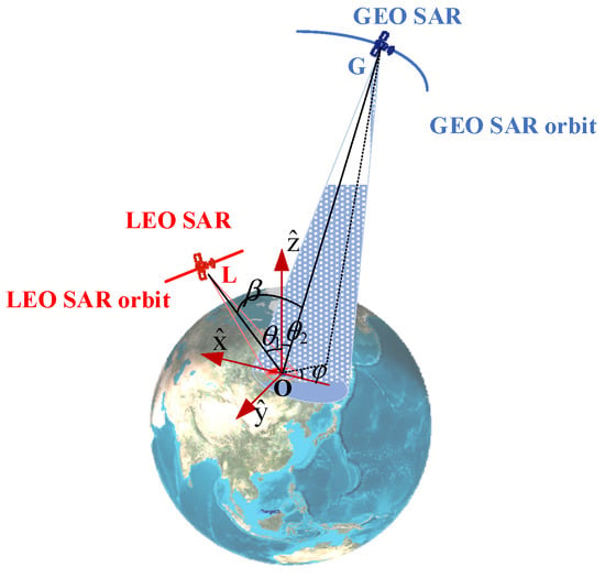
Figure 1.
Schematic diagram when a GEO SAR and a LEO SAR observe the same target.
The echo of a single target with RFI and noise can be expressed as [35]
where is the target signal, is the RFI signal, is the noise. Then, SAR processing can be described as
where is the imaging result, is the point target response of SAR processing, and , , are the SAR processing result of , and , respectively. Obviously, RFI enters the receiver and signal processing system with the target signal at the same time. As a result, the output image is the linear summation in the complex domain, performing as noise or ghost targets and deteriorating the image.
We adopted SINR to judge whether the RFI can be neglected or not. When the image SINR falls below 5 dB, the image quality is poor, leading to loss of detailed information [36]. Considering the SAR receiver, the definition of SINR is [32,33]
where is the power of , which can be obtained from the SAR radar equation [37].In digital signal processing, echo focusing is considered as coherent accumulation, thus, its amplitude gain can be written as , where and are the sampling point number in the range direction and the azimuth direction, respectively. Since, and , where , , and are pulse width, sampling rate, integration time and pulse repetition frequency (PRF) of the disturbed SAR system, respectively, can be written as
where , , and are the peak transmitted power, antenna gain, slant range and wavelength of the disturbed SAR system, respectively. is the normalized backscatter coefficient, and are azimuth resolution and ground range resolution, respectively.
is the power of . Since the thermal noise is usually considered as a stochastic process, it is superimposed incoherently in SAR processing. As a result, the power gain of the thermal noise is . Then, can be written as
where is the Boltzmann constant, is the thermal noise temperature, is the bandwidth of the receiver and is the gain caused by the incoherent accumulation of thermal noise.
is the power of . Since RFI comes from other spaceborne SARs, according to the bistatic radar equations [38], RFI power affecting the pixel after SAR processing can be written as
where , and are the peak transmitted power, antenna gain and slant range of the RFI source SAR system, respectively. is the bistatic scattering coefficient, is the antenna aperture area of the disturbed SAR, is the receiving aperture area, and is the gain obtained by RFI in SAR processing.
2.2. Times Series of GEO SARs and LEO SARs
For one observation, the GEO SAR may keep working for several hours (or dozens of minutes) with a quite low PRF (hundreds of Hertz) and the LEO SAR may only work for several minutes with thousands of Hertz. As shown in Figure 2, is the time interval between the first pulse of the LEO SAR and the first pulse of the GEO SAR; the green envelope is from GEO SAR and the red envelope is from LEO SAR. Obviously, the RFI from GEO SAR may be received every few LEO SAR pulses, while the RFI from LEO SAR may be received several times in one GEO SAR pulse. In fact, the RFI far away from the echo signal in fast-time domain cannot affect the imaging result, so Figure 2 only shows the RFI from LEO SAR, which is close to the GEO SAR pulses.
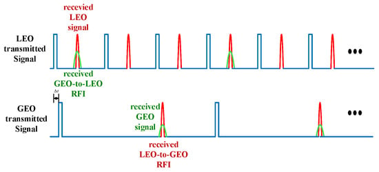
Figure 2.
Time series of GEO SARs and LEO SARs.
2.3. Gains in Mismatched Filtering
RFI signals from other SAR systems usually have a different Frequency Modulation (FM) rate from the disturbed SAR system and, as a result, they can be mismatched and defocused. Even so, RFI from the SAR systems could still obtain certain gain. Generally, the gain is much smaller than that of matched filtering due to the chirp signal form of RFI. To evaluate the image SINR accurately, we discuss the gains obtained in mismatched filtering.
According to the digital signal processing theory and the principle of stationary phase (POSP), when mismatched filter is adopted on two chirp signals with a time domain amplitude of 1, different pulse width ( and ) and FM rate ( and ), and the sampling rate satisfies the Nyquist Sampling Theorem for both signals, the output can be written as
where , and are the FM rate and pulse width of the output signal, and they can be written as (8) and (9), respectively. Details are given in Appendix A.
Obviously, the pulse width after mismatched filtering is related to the smaller bandwidth and FM rate of the two chirp signals.
Moreover, the amplitude gain obtained in mismatched filtering can be expressed as
where is the sampling rate [39]. Note that the gain in this paper refers to that in digital signal processing in particular.
2.4. RFI Power Affecting the Pixel after SAR Processing
Based on Section 2.1, both and are easy to estimate, but deserves further study. According to (6), the gain obtained by RFI in SAR processing and the receiving aperture area are crucial to . Both the two elements are different for GEO-to-LEO RFI and LEO-to-GEO RFI. Thus, we will discuss the power of GEO-to-LEO RFI and LEO-to-GEO RFI, respectively.
2.4.1. GEO-TO-LEO RFI
When the beam coverage overlaps, RFI between GEO SARs and LEO SARs may occur. The beam coverage of GEO SARs is usually much larger than that of LEO SARs. Therefore, only LEO SAR beam coverage should be considered. As shown in Figure 3, the red frame represents the beam coverage of a LEO SAR (the antenna of LEO SARs is usually rectangular). Point A, B, C, and D are illuminated by both the LEO SAR and the GEO SAR at the same time. Thus, the RFI, which is transmitted by the GEO SAR and scattered by these points, would affect the LEO SAR. The RFI scattered by point A produces a yellow interference zone after the SAR processing. Since the GEO-to-LEO RFI scattered by point A and point B has the same parameter for (9), according to the principle of SAR, point B, located in the same range cell as point A, would produce the same interference zone as point A. The same is true for point C and D. Point O is at the junction of the yellow interference zone (generated by A and B) and the pink interference zone (generated by C and D). Based on the geometry, the interference zone formed by all the units in zone ABCD will affect cell O. Assuming there are N cells in total, the RFI power received by unit O can be written as , where is the RFI power of the ith cell.
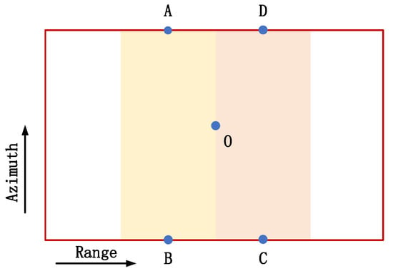
Figure 3.
Schematic diagram of RFI; Point A, B, C, D and O are the five targets in the scene. A and B are in the same range cell, and the same is true for point C and D. Point O is the center of ABCD. The red frame represents the beam coverage of the LEO SAR and the yellow interference zone is from the RFI signal at point A and the pink interference zone is from the RFI signal at point D.
Therefore, the size of zone ABCD is the key to calculate the RFI power affecting cell O. Obviously, the size of zone ABCD can be estimated by the product of AB and BC. AB is the azimuth direction length of beam coverage of LEO SAR on the ground. BC is the length of the interference zone in the range direction; we call it , which can be written as
where is the incidence angle of LEO SAR and is the time width after pulse compression in the range direction; according to (9), it can be written as
where and are the FM rate and pulse width of GEO SAR, respectively. and are the FM rate and pulse width of LEO SAR, respectively.
Finally, the receiving aperture area can be expressed as
where and are the beamwidth and slant range of LEO SAR, respectively.
Generally, mismatch occurs for GEO-to-LEO RFI in both the range direction and azimuth direction. In this paper, we focus on the case that sampling rate satisfies the Nyquist theorem in range-direction. Then, according to (10), the gain of GEO-to-LEO RFI in the range direction can be written as
where is the sampling rate of the LEO SAR. When the Nyquist theorem is not satisfied, the gain can be given by a numerical simulation, which is detailed below, but the range direction spectral aliasing is not discussed in our paper.
The PRF of LEO SARs is usually much higher than that of GEO SARs; that is, a LEO SAR receives multiple pulses from itself before receiving a pulse from a GEO SAR (as shown in Figure 2), which is equivalent to down-sampling, causing spectrum aliasing in the azimuth direction. Therefore, the gain of GEO-to-LEO RFI in the azimuth direction is given by a numerical simulation. The step is shown in Table 1, where the subscript SAR represents the disturbed SAR, and the subscript i represents the RFI source. In this case, is the FM rate of the LEO SAR in the azimuth direction, is the integration time of the LEO SAR, and is the FM rate of the GEO-to-LEO RFI in the azimuth direction, which can be written as
where and are the velocity and slant range of the GEO SAR, respectively. and are the velocity and slant range of the LEO SAR, respectively.

Table 1.
Steps of the numerical simulation.
Therefore, the gain obtained by GEO-to-LEO RFI in SAR processing can be written as
2.4.2. LEO-TO-GEO RFI
According to Figure 3, is related to the size of the interference zone. Like GEO-to-LEO RFI, the azimuth length of corresponds to the azimuth direction length of the LEO SAR beam coverage on the ground. However, the range direction length of the interference zone generated by the LEO-to-GEO RFI is different from that of the GEO-to-LEO RFI (written as (11)). As shown in Figure 4, the LEO-to-GEO RFI can have a much larger range migration than GEO SAR signals due to the long integration time of the GEO SAR and the different velocity between the GEO SAR and the LEO SAR. However, there is little difference on the migration between the LEO SAR and the GEO-to-LEO RFI due to the short integration time of the LEO SAR. When the Back Projection (BP) algorithm is adopted, the RFI will be accumulated along the migration direction of the SAR signals. Thus, the interference zone generated by the LEO-to-GEO RFI will spread in the range direction due to its inconsistent migration direction with the GEO SAR signals, while the interference zone generated by the GEO-to-LEO RFI will remain unchanged due to its similar migration direction with the LEO SAR signals.
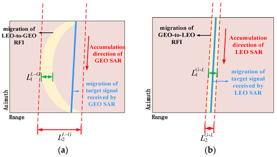
Figure 4.
Relationship between migration and the accumulation direction. is the range direction length of the interference band before the BP algorithms (after the range compression). is the range direction length of the interference band after the BP algorithms. (a) LEO-to-GEO RFI (b) GEO-to-LEO RFI.
As a result, the width in the range direction is related to the slant range, which can be expressed as
where and are the maximum and minimum slant range of LEO-to-GEO RFI. In summary, of LEO-to-GEO RFI can be expressed as
Similarly, we only discuss the case that the Nyquist theorem is satisfied in the range-direction. Like (14), the gain obtained by LEO-to-GEO RFI from range compression can be written as
where is the sampling rate of the GEO SAR.
Since the PRF of LEO SARs is much higher than that of GEO SARs, spectrum aliasing will occur in the azimuth-direction. Therefore, the gain obtained by LEO-to-GEO RFI in the azimuth-direction is also given by the numerical simulation shown in Table 1. In this case, is the FM rate of the GEO SAR in the azimuth direction, is the integration time of the GEO SAR, and is the FM rate of the LEO-to-GEO RFI in the azimuth direction. Furthermore, Step 3 should be skipped.
However, based on Figure 4, the interference zone can spread in the range direction after the BP algorithms, and, as a result, the gain obtained by LEO-to-GEO RFI in the azimuth-direction can decrease; the gain after decreasing is referred to as . Obviously, . Referring to (11), the length of interference zone in the range direction before widening can be expressed as
where is the incidence angle of GEO SAR. Thus, the range direction length of the interference zone changes from to , where . represents the total power before widening, then it can be expressed as
where is the RFI power entering the receiver. denotes the total power after widening and can be written as
Based on the conservation of energy, . It is apparent that .
Therefore, the gain obtained by LEO-to-GEO RFI in SAR processing can be written as
2.4.3. Discussion on GEO-TO-LEO RFI and LEO-TO-GEO RFI
According to the derivations above, the power of GEO-to-LEO RFI and LEO-to-GEO RFI affecting the pixel after SAR processing can be given in the same form, written as
where and are the peak transmitted power and antenna gain of RFI source SAR system. , , and are the antenna aperture area, sampling rate and the incidence angle of the disturbed SAR. These symbols have different meanings in different cases; for example, represents the peak transmitted power of GEO SAR when GEO SAR is the source of interference, while it represents the peak transmitted power of LEO SAR when LEO SAR is the source of interference. Similarly, represents the incidence angle of LEO SAR when GEO SAR is the source of interference, while it represents the incidence angle of GEO SAR when LEO SAR is the source of interference. Furthermore, and are given by Table 1 and (12), respectively.
Differences in power calculation between GEO-to-LEO RFI and LEO-to-GEO RFI mainly lie in azimuth gain, considering spectrum aliasing and the interference zone widening caused by different range migration. On one hand, to solve the spectrum aliasing, a numerical simulation is used and a unified symbol is used to replace the entire numerical simulation. On the other hand, in the case of LEO-to-GEO RFI, the interference zone widening caused by range migration generates a change in some intermediate variables (such as the range direction width of the interference zone and the azimuth gain of RFI), but the total energy remains unchanged. Therefore, the LEO-to-GEO RFI power can still be simplified to the same form as the GEO-to-LEO RFI. Moreover, we analyzed the RFI from the perspective of the BP algorithms in this paper, but the results do not depend on the imaging algorithms.
Combining (3)–(5), (24), the final expression of SINR is derived as (25), where , is the LEO SAR bandwidth and is the LEO SAR bandwidth. Furthermore, three constants , and are introduced to illustrate the connection between system parameters such as bandwidth, pulse width, etc., and image SINR, and they can be written as (26)–(28), respectively.
Some conclusions can be inferred from (25) as follows:
(1) The image SINR of the disturbed SAR decreases as the bandwidth of the RFI source SAR becomes smaller. Once the bandwidth of the RFI source SAR is smaller than that of the disturbed SAR, image SINR does not depend on the bandwidth of the RFI source SAR.
(2) The large pulse width of the RFI source SAR or small pulse width of the disturbed SAR will cause small image SINR, leading to poor image quality.
(3) The large beamwidth of LEO SARs in the azimuth direction and bistatic scattering coefficient will also increase the impacts on imaging.
3. Numerical Verification
Computer simulations were performed to verify the proposed SINR expressions in the presence of RFI and give the SINR value with different system parameters and bistatic configurations.
In the experiment, we used System Tool Kit (STK) software to generate the orbits and adopt the BP algorithms to obtain the SAR image. As shown in Figure 1, the center of the scene was set to (N, ), and the parameters of LEO SARs refer to PALSAR-2 [40]. The parameters of LEO SARs and GEO SARs are shown in Table 2.

Table 2.
Parameters of LEO SAR and GEO SAR.
3.1. Verification of the SINR Expressions in the Presence of RFI
In the aspect of GEO-to-LEO RFI, the target signal from the scene center and the RFI signal from the GEO SAR scattered by the scene center were generated and focused. Then, the power of the image pixel both in and without the presence of RFI were obtained, compared with the theoretical value from (16). As shown in Table 3, the error between the evaluated power and calculated power after BP algorithm is small, verifying the expression of the GEO-to-LEO RFI gain.

Table 3.
GEO-to-LEO RFI focusing results.
In the aspect of LEO-to-GEO RFI, firstly, to illustrate the migration difference between the LEO-to-GEO RFI and the GEO-to-LEO RFI and explain the interference zone spread of the LEO-to-GEO RFI in the range direction, we generated a target echo received by the GEO SAR, a LEO-to-GEO RFI signal, a target echo received by the LEO SAR, and a GEO-to-LEO RFI signal according to Table 2. All of them were scattered by the scene center and adopted matched filter in the range direction. The results are shown in Figure 5. Obviously, Figure 5 agrees with Figure 4, and the length of interference in the range direction widened after the BP algorithm and can be expressed as (17). Then, to further demonstrate (17), the target echo and the RFI signal from the LEO SAR scattered by the point A and D were obtained and focused, respectively. Thus, the range-direction length of the interference zone generated by point A and D was obtained by simulation, which is shown in Table 4 compared with the theoretical value from (17). It is apparent that the range direction length of the interference zone is related to the slant range, and there is little change for different points in the same scene; as a result, it can be given using the slant range of the scene center. In addition, there is a drift of the interference zone in the range direction due to the large migration; however, it does nothing, with the area affecting a single resolution cell due to the same value for different points.
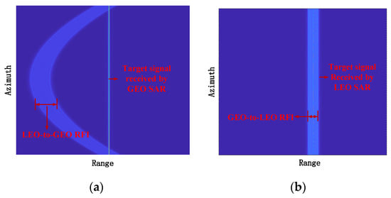
Figure 5.
Range compression result. (a) the RFI which is transmitted by the LEO SAR, scattered by the scene center, and received by the GEO SAR and the target echo which is transmitted and received by the GEO SAR; (b) the RFI which is transmitted by the GEO SAR, scattered by the scene center, and received by the LEO SAR and the target echo which is transmitted and received by the LEO SAR.

Table 4.
Length and drift of the interference zone in range-direction for different points and integration time.
Furthermore, the length in the range direction and the average power, both before and after the interference zone spread, are given in Table 5, respectively. This indicates that the processing follows the conservation of energy, which verifies (23).

Table 5.
Focusing results of LEO-to-GEO RFI scattered by point A.
According to Table 2, there are 200 pixels on the ground corresponding to the azimuth beamwidth. Additionally, the length of the interference zone is about 100 pixels. Considering the computing resources, the scene (rectangle ABCD) is set to 200 × 200 pixels. Figure 6a illustrates the imaging results of the four points (A, B, C and D). According to the geometry, the interference zone of other points spread in area Y and only points in the area X have the same RFI power as point O while imaging the whole scene, as shown in Figure 6b. Therefore, the power of area X (red area) is equal to the power of RFI affecting a single resolution cell. The value from (24) and the experiments are shown in Table 6, demonstrating the reliability of RFI power expression.
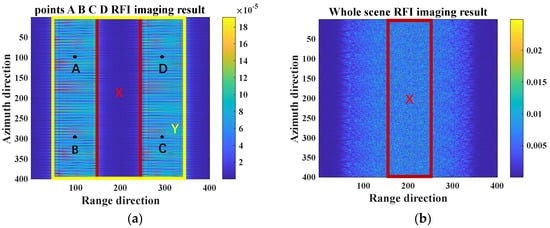
Figure 6.
Results of BP algorithm. (a) point A, B, C, D; (b) the whole scene.

Table 6.
Power affecting a signal resolution cell from RFI.
3.2. SINR in Different System Parameters of LEO SARs and GEO SARs
According to the parameters in Table 2, the SINR of images are shown in Figure 7 and Figure 8, while the GEO SAR and the LEO SAR demonstrate various bandwidth and pulse width.
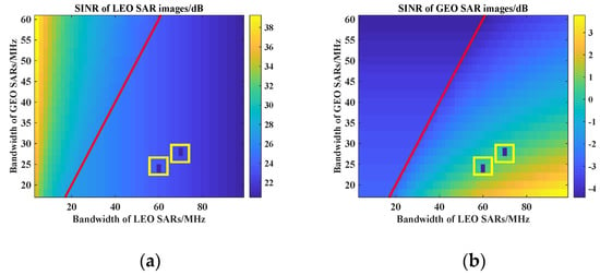
Figure 7.
The relationship between bandwidth and SINR of LEO SARs and GEO SARs images in the presence of scattered wave RFI (). The red line indicates that the LEO SAR has the same bandwidth as the GEO SAR, and the invalid value in the yellow box indicates the LEO SAR has the same FM rate as the GEO SAR; (a) the integration time is 0.5 s; (b) the integration time is 220 s.
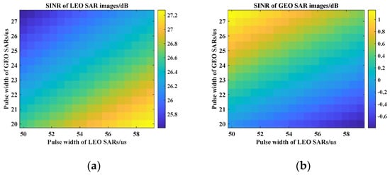
Figure 8.
The relationship between pulse width and SINR of LEO SARs and GEO SARs images in the presence of scattered wave RFI (); (a) the integration time is 0.5 s; (b) the integration time is 220 s.
Obviously, the impact is more serious when the disturbed system has a larger bandwidth and the RFI source has a smaller bandwidth. For example, it is better for LEO SAR images if the LEO SAR has a small bandwidth and the GEO SAR has a large bandwidth. Similarly, it is better for GEO SAR images if the GEO SAR has a small bandwidth and the LEO SAR has a large bandwidth.
In addition, the large ratio of the pulse width of the RFI source to the disturbed system can have serious effects on SINR; for example, GEO SAR images will be destroyed more seriously as the pulse width of the LEO SAR increases compared with the GEO SAR. Therefore, high-quality images of LEO SARs and GEO SARs have conflicting requirements for pulse width, which should be chosen based on the demand from designers.
3.3. SINR under Different Bistatic Configurations
Generally, the bistatic configuration can be categorized into two types, including the specular scattering case and the non-specular scattering case, as shown in Table 7 [38]. Take Figure 1 for example. For the out-of-plane case, turns minimum when approaches , and it is almost same as that in the in-plane case when is near or . achieves maximum in the case of specular scattering, which is a small probability event. While is , and , the backscatter case occurs; is larger than that in other cases but demonstrates specular scattering.

Table 7.
Specular scattering case and non-specular scattering case.
In this paper, the bistatic scattering coefficient of bare soil in L band was given using an advanced integral equation model (AIEM) [41] based on the parameters shown in Table 2 (in order to overcome the thermal noise, the GEO SAR transmission power is 10 kw and the antenna diameter is 25 m in this case). Then, the corresponding SINR was obtained, which is shown in Figure 9.
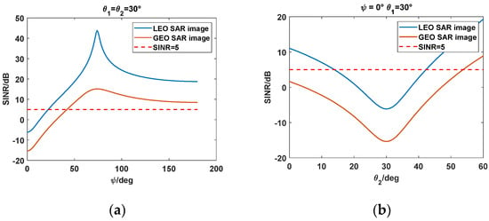
Figure 9.
Image SINR, where the integration time of GEO SARs is 220 s and the integration time of LEO SARs is 0.5 s. The azimuth beamwidth of LEO SARs is 1.47°; (a) ; (b) .
According to Figure 9a, obviously, the image quality is poor in the case of specular scattering (). Additionally, when approaches , the image quality is high due to the small value of . The backscatter case resulted in a larger scattering coefficient; however, the impact can be still ignored. In addition, in the in-plane case, smaller differences between and will lead to poor image from Figure 9b. Finally, the impact of LEO-to-GEO RFI is more serious than that of GEO-to-LEO RFI in the same configuration.
4. Discussion on Probability of Specular Scattering Case
According to the analysis in the previous section, when the specular scattering case occurs, the image SINR will fall below 5 dB and the image quality will be poor, leading to the loss of detailed information. In fact, specular scattering requires a very special geometric configuration, and its probability between a single GEO SAR and a single LEO SAR is generally small. However, the satellite constellation will be an important form of spaceborne SAR in the future. The growing number of LEO SAR constellations is expected to increase the specular scattering RFI occurrence between GEO SARs and LEO SARs. Therefore, considering the LEO SAR constellations, we evaluated the probability of specular scattering RFI and presented the probability for different orbital elements.
Taking in account observations of China, the probability of the specular scattering case was analyzed. The probability of GEO SAR receiving specular scattering RFI can be written as
where is the total time for the specular scattering case in China, and is the total time for GEO SAR illuminating in China.
Similarly, the probability of LEO SAR receiving specular scattering RFI can be written as
where is the total time for LEO SAR illuminating in China.
Since specular scattering needs the same incident angle, we suppose that the beam shape of both the GEO SAR and the LEO SAR are circular. Furthermore, we think that GEO SARs have the capability of right look function and LEO SARs have the capability of both the right look function and the left look function. Generally, the number of GEO SARs is much smaller than that of LEO SARs. Therefore, we considered a case involving both a GEO SAR and a LEO SAR constellation. Figure 10 illustrates the geometry of the GEO SAR and the LEO SAR constellation. The orbit elements of the GEO SAR are given in Table 8. The LEO SAR constellation is a Walker Patten constellation for the sun-synchronous orbit. Then, we obtained the position of GEO SARs, LEO SARs, and their boresight using the STK. Finally, according to Table 8, (29) and (30), we evaluated the probability.
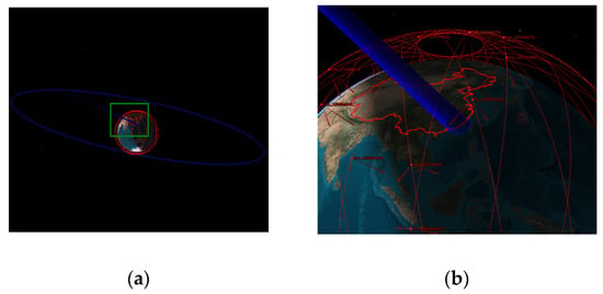
Figure 10.
The sketch of simultaneous observation of China by a GEO SAR and a LEO SAR constellation (Walker Patten 20/1/1); (b) is the zoom of the green box in (a).

Table 8.
Orbital elements of the GEO SAR and LEO SAR constellation.
To illustrate how the altitude and the satellite number of the LEO SAR constellation affect the probability of specular scatter, we estimated and in different orbit altitudes (varying from 500 km to 1000 km), different pattens (20/1/1 and 10/1/1), and different true anomaly of the seed satellite. The constellation parameters are detailed in Table 8 and the results are shown in Figure 11 and Figure 12. Every box line draws on the probability of different true anomaly in the same orbit altitude and the same Walker patten, which is shown in Appendix B.
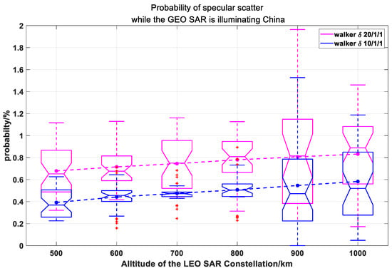
Figure 11.
Probability of specular scatter while the GEO SAR is illuminating China. The magenta box line shows the case of a LEO SAR constellation which uses a 20/1/1 walker pattern. The magenta points are the average of the probability for every altitude in 20/1/1 walker pattern. The blue box line shows the case of a LEO SAR constellation which uses a 10/1/1 walker patten. The blue points are the average of the probability for every altitude in 10/1/1 walker pattern.
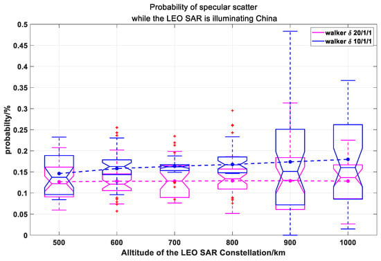
Figure 12.
Probability of specular scatter while the LEO SAR is illuminating China. The magenta box line shows the case of a LEO SAR constellation which uses a 20/1/1 walker pattern. The magenta points are the average of the probability for every altitude in 20/1/1 walker pattern. The blue box line shows the case of a LEO SAR constellation which uses a 10/1/1 walker patten. The blue points are the average of the probability for every altitude in 10/1/1 walker pattern.
Comparing Figure 11 with Figure 12, can approach 1.9%, but cannot reach 0.5%. This is because there is only one GEO SAR with a right look function but there are 20 LEO SARs with right look function and left look function in our study. As a result, the total time for LEO SARs observation in China is much longer than that of GEO SAR, but the time for specular scatter is the same, causing the large difference between and in this case. Moreover, when the number of LEO SARs doubles, increases but decreases because the specular scatter time does not grow as the total time for LEO SAR observation of China. This indicates that the growing number of LEO SARs (or GEO SARs) could lead to higher (or ). Furthermore, it is apparent that the probability becomes higher as the orbit altitude increases. Since the orbit altitude increases, the coverage of the LEO SAR is larger. Thus, the specular scatter RFI is more likely to occur.
Furthermore, the probability will increase as the altitude becomes higher and the number of satellites grows. Therefore, in the future, it will be necessary to suppress the RFI between the two systems, due to the growing number of LEO SARs. Furthermore, it is also worth noting that the orbit design of LEO SARs should be optimized to avoid this case as much as possible.
5. Conclusions
This paper established a RFI impact quantitative analysis model and derived the accurate RFI power, which is suitable for both GEO-to-LEO RFI and LEO-to-GEO RFI. Based on the theoretical analysis, accurate SINR of disturbed SAR systems was obtained, allowing the impact of RFI on SAR images to be quantitatively evaluated. The theoretical analysis was validated by experiments.
Furthermore, the SINR of images were given while the GEO SAR and the LEO SAR were demonstrated to have various bandwidths and pulse widths. It was found that the impact is more serious when the RFI source has a smaller bandwidth, and the large ratio of the pulse width of the RFI source compared to the disturbed system was also shown to seriously effect SINR. This indicates that the high-quality images of LEO SARs and GEO SARs have conflicting requirements for pulse width, which should be chosen based on the demand from designers.
The SINR, corresponding to different bistatic configurations, was also discussed. We conclude that when the target forms a specular scattering geometry with a GEO SAR and a LEO SAR, the bistatic scattering RFI will lead to poor image quality, while the effects can be neglected in other cases. In addition, the impact of LEO-to-GEO RFI is more serious than that of GEO-to-LEO RFI in the same configuration. Furthermore, we presented the probable specular scatter for several designs of the LEO SAR constellation. The results implied the necessity to suppress the RFI between the GEO SAR and LEO SAR system due to the growing number of LEO SAR constellations and suggested that the orbit design of LEO SARs should be optimized to avoid this case as much as possible.
In this paper, we discussed the RFI between LEO SARs and GEO SARs. In the future, this theory could be extended to the RFI between any two SAR systems, including the LEO-to-LEO RFI and GEO-to-GEO RFI. In addition, RFI suppression from both signal processing and the optimization of orbital parameters should be considered.
Author Contributions
X.D. and Y.S. conceived and designed the methods and wrote the paper; Y.S. performed the simulation and analyzed the data. Z.C. and Y.L. commented about the paper and helped editing. C.H. gave many suggestions. All authors have read and agreed to the published version of the manuscript.
Funding
This research was funded in part by the National Natural Science Foundation of China under Grant Nos. 61960206009, 61971039, 61971037, Distinguished Young Scholars of Chongqing (Grant No. cstc2020jcyj-jqX0008), National Ten-thousand Talents Program ‘Young top talent’ (Grant No. W03070007), and the Special Fund for Research on National Major Research Instruments (NSFC Grant Nos. 61827901, 31727901).
Conflicts of Interest
The authors declare no conflict of interest.
Appendix A
Let us suppose that and are the frequency domain expression of two chirp signals with time domain amplitude of 1, different pulse width ( and ) and FM rate ( and ), so they can be written as
Considering as the frequency domain matched filter, matched filtering operates and the result in frequency domain can be written as
When approaches , (A3) will degenerate into a simple rectangle function and it can be written as
Then, the amplitude gain for matched filter can be written as
where is the sampling rate [39].
Generally, the FM rate of GEO SAR and LEO SAR are quite different. Therefore, when , (A3) can be written as
It’s apparent that can be seen as the frequency domain expression of a chirp signal with FM rate of and pulse width of . Then, and can be written as
According to the principle of stationary phase (POSP), can be written as
Appendix B
According to Table 8, under different orbital altitudes and Walker patten, we make the true anomaly of the seed satellite of the LEO SAR constellation traversing 0–360 degrees with an interval of 10 degrees and estimate the probability. The results are shown in Figure A1 and Figure A2.
From Figure A1 and Figure A2, it’s clear that the probability of GEO SAR receiving specular scattering RFI is much higher than that of LEO SARs and when the number of LEO SARs doubles, increases but decreases. These conclusions agree with Section 4 and we have illustrated them in detail. Another important conclusion is that different true anomaly of seed satellite of the LEO SAR constellation leads to different probability. In the future, in order to achieve various functions such as InSAR and continuous observation of certain areas, any true anomaly design is possible, thus, the probability is also changeable.
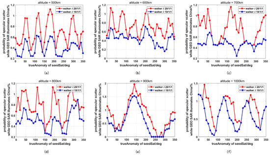
Figure A1.
Probability of specular scatter while the GEO SAR is illuminating China changing with the true anomaly of the seed satellite. The red line represents the probability considering a LEO SAR constellation which uses a 20/1/1 walker pattern and the blue line represents the probability considering a LEO SAR constellation which uses a 10/1/1 walker pattern. (a–f) represent the altitude of 500 km, 600 km, 700 km, 800 km, 900 km, and 1000 km, respectively.
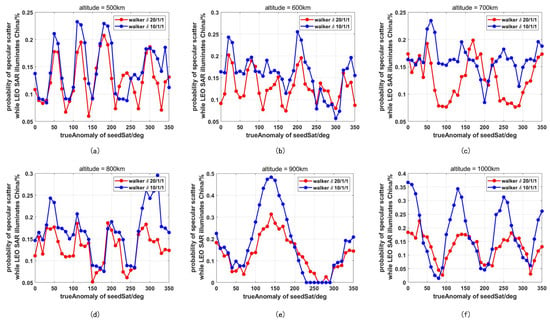
Figure A2.
Probability of specular scatter while the LEO SAR is illuminating China changing with the true anomaly of the seed satellite. The red line represents the probability considering a LEO SAR constellation which uses a 20/1/1 walker pattern and the blue line represents the probability considering a LEO SAR constellation which uses a 10/1/1 walker pattern. (a–f) represent the altitude of 500 km, 600 km, 700 km, 800 km, 900 km, and 1000 km, respectively.
References
- Moreira, A.; Prats-Iraola, P.; Younis, M.; Krieger, G.; Hajnsek, I. A tutorial on synthetic aperture radar. Geosci. Remote Sens. Mag. IEEE 2013, 1, 6–43. [Google Scholar] [CrossRef] [Green Version]
- Reigber, A.; Scheiber, R.; Jager, M.; Prats-Iraola, P.; Hajnsek, I.; Jagdhuber, T.; Papathanassiou, K.P.; Nannini, M.; Aguilera, E.; Baumgartner, S. Very-High-Resolution Airborne Synthetic Aperture Radar Imaging: Signal Processing and Applications. Proc. IEEE 2013, 101, 759–783. [Google Scholar] [CrossRef] [Green Version]
- Kussul, N.; Shelestov, A.; Skakun, S. Flood Monitoring from SAR Data. In Use of Satellite and In-Situ Data to Improve Sustainability; Springer: Dordrecht, The Netherlands, 2011. [Google Scholar]
- Raucoules, D.; Colesanti, C.; Carnec, C. Use of SAR interferometry for detecting and assessing ground subsidence. C. R.—Geosci. 2007, 339, 289–302. [Google Scholar] [CrossRef]
- Meyer, F.J.; Nicoll, J.B.; Doulgeris, A.P. Correction and Characterization of Radio Frequency Interference Signatures in L-Band Synthetic Aperture Radar Data. IEEE Trans. Geosci. Remote Sens. 2013, 51, 4961–4972. [Google Scholar] [CrossRef] [Green Version]
- Chen, D.; Yang, J.; Wu, J.; Hao, T.; Ming, H. Spectrum occupancy analysis based on radio monitoring network. In Proceedings of the 1st IEEE International Conference on Communications in China (ICCC), Beijing, China, 15–17 August 2012. [Google Scholar]
- Islam, M.H.; Koh, C.L.; Oh, S.W.; Qing, X.; Toh, W. Spectrum Survey in Singapore: Occupancy Measurements and Analyses. In Proceedings of the 3rd International Conference on Cognitive Radio Oriented Wireless Networks and Communications (CrownCom), Singapore, 15–17 May 2008. [Google Scholar]
- Küçük, İ.; Üler, İ.; Öz, Ş.; Onay, S.; Özdemir, A.; Gülşen, M.; Sarıkaya, M.; DağTekin, N.; Özeren, F. Site selection for a radio astronomy observatory in Turkey: Atmospherical, meteorological, and radio frequency analyses. Exp. Astron. 2012, 33, 1–26. [Google Scholar] [CrossRef]
- Koutsoudis, T.; Lovas, L.A. rf interference suppression in ultrawideband radar receivers. Proc. SPIE—Int. Soc. Opt. Eng. 1995, 2487, 107–118. [Google Scholar]
- Nguyen, M.T.; Long, B.L. Adjacent channel interference cancellation for robust spectrum sharing in satellite communications systems. In Proceedings of the 2017 IEEE 28th Annual International Symposium on Personal, Indoor, and Mobile Radio Communications (PIMRC), Montreal, QC, Canada, 8–13 October 2017. [Google Scholar]
- Shimada, M. L-band radio interferences observed by the JERS-1 SAR and its global distribution. In Proceedings of the 2005 IEEE International Geoscience and Remote Sensing Symposium, Seoul, Korea, 29 July 2005. [Google Scholar]
- Rosen, P.A.; Hensley, S.; Le, C. Observations and mitigation of RFI in ALOS PALSAR SAR data: Implications for the DESDynI mission. In Proceedings of the Radar Conference (RADAR ‘08), Rome, Italy, 26–30 May 2008. [Google Scholar]
- Meyer, F.J.; Nicoll, J.B.; Doulgeris, A.P. Characterization and extent of randomly-changing radio frequency interference in ALOS PALSAR data. In Proceedings of the 2011 IEEE International Geoscience and Remote Sensing Symposium, Vancouver, BC, Canada, 24–29 July 2011. [Google Scholar]
- Sentinel-1A-Annual-Performance-Report-2015. Available online: https://sentinel.esa.int/documents/247904/1814124/Sentinel-1A-Annual-Performance-Report-2015.pdf/1285c804-d83e-48e9-a934-4db30208f28a?t=1461670723000 (accessed on 8 April 2020).
- Saini, O.; Bhardwaj, A.; Chatterjee, R.S. Radio Frequency Interference Pattern Detection from Sentinel-1 SAR Data Using U-NET-Like Convolutional Neural Network. In Proceedings of the MOL2NET 2020 International Conference on Multidisciplinary Sciences, 6th Edition Session USINEWS-04: US-IN-EU Worldwide Science Workshop Series, Duluth, MN, USA, 21–23 June 2020. [Google Scholar]
- Nabil, H.; Jie, C.; Kamel, H.; Hui, K. Bidirectional notch filter for suppressing pulse modulated radio-frequency-interference in SAR data. In Proceedings of the IEEE Geoscience and Remote Sensing Symposium, Quebec City, QC, Canada, 13–18 July 2014. [Google Scholar]
- Van Leijen, F.; Rommen, B.; Davidson, M.; Hanssen, R. The impact of ground-based uncorrelated radio frequency interference (RFI) sources on satellite radar interferometric ground motion analysis. In Proceedings of the 2015 IEEE International Geoscience and Remote Sensing Symposium (IGARSS), Milan, Italy, 26–31 July 2015; pp. 4093–4096. [Google Scholar]
- Yang, L.; Zheng, H.; Feng, J.; Li, N.; Chen, J. Detection and suppression of narrow band RFI for synthetic aperture radar imaging. Chin. J. Aeronaut. 2015, 28, 1189–1198. [Google Scholar] [CrossRef] [Green Version]
- Tao, M.; Su, J.; Huang, Y.; Wang, L. Mitigation of Radio Frequency Interference in Synthetic Aperture Radar Data: Current Status and Future Trends. Remote Sens. 2019, 11, 2438. [Google Scholar] [CrossRef] [Green Version]
- Shao, P.; Lu, X.; Huang, P.; Xu, W.; Dong, Y. Impact Analysis of Radio Frequency Interference on SAR Image Ship Detection Based on Deep Learning. In Proceedings of the 2020 IEEE International Geoscience and Remote Sensing Symposium (IGARSS), Waikoloa, HI, USA, 26 September–2 October 2020. [Google Scholar]
- Reigber, A.; Ferro-Famil, L. Interference Suppression in Synthesized SAR Images. IEEE Geosci. Remote Sens. Lett. 2005, 2, 45–49. [Google Scholar] [CrossRef]
- Ding, B.; Mao, S.X.; Xing, D.L. Analysis of the effect of radio frequency interference on interferometric phase. In Proceedings of the 2010 IEEE International Geoscience and Remote Sensing Symposium, Honolulu, HI, USA, 25–30 July 2010. [Google Scholar]
- Reigber, A.; Ulbricht, A. P-band repeat-pass interferometry with the DLR experimental SAR (ESAR): First results. In Proceedings of the 1998 IEEE International Geoscience and Remote Sensing Symposium, Seattle, WA, USA, 6–10 July 1998. [Google Scholar]
- Guarnieri, A.M.; Rocca, F.; Ibars, A.B. Impact of atmospheric water vapor on the design of a Ku band geosynchronous SAR system. In Proceedings of the 2009 IEEE International Geoscience and Remote Sensing Symposium, Cape Town, South Africa, 12–17 July 2009; Volume 2, pp. II-945–II-948. [Google Scholar]
- Zhou, F.; Wu, R.; Xing, M.; Bao, Z. Eigensubspace-Based Filtering with Application in Narrow-Band Interference Suppression for SAR. IEEE Geosci. Remote Sens. Lett. 2007, 4, 75–79. [Google Scholar] [CrossRef]
- Andrea, M.G.; Davide, G.; Andrea, R. Identification of C-Band Radio Frequency Interferences from Sentinel-1 Data. Remote Sens. 2017, 9, 1183. [Google Scholar] [CrossRef] [Green Version]
- Tomiyasu, K. Synthetic aperture radar in geosynchronous orbit. In Proceedings of the Antennas & Propagation Society International Symposium, Washington, DC, USA, 15–19 March 1978. [Google Scholar]
- Hobbs, S.; Mitchell, C.; Forte, B.; Holley, R.; Snapir, B.; Whittaker, P. System design for geosynchronous synthetic aperture radar missions. IEEE Trans. Geosci. Remote Sens. 2014, 52, 7750–7763. [Google Scholar] [CrossRef] [Green Version]
- Rodon, J.R.; Broquetas, A.; Guarnieri, A.M.; Rocca, F. Geosynchronous SAR focusing with atmospheric phase screen retrieval and compensation. IEEE Trans. Geosci. Remote Sens. 2013, 51, 4397–4404. [Google Scholar] [CrossRef]
- Cheng, H.; Zca, C.; Yl, D.; Xda, E.; Sh, F. Research Progress on Geosynchronous Synthetic Aperture Radar. Fundam. Res. 2021, 1, 346–363. [Google Scholar]
- Chen, Z.; Hu, C.; Dong, X.; Li, Y.; Hobbs, S. Coherence-Based Geosynchronous SAR Tomography Employing Formation Flying: System Design and Performance Analysis. IEEE Trans. Geosci. Remote Sens. 2021, 59, 1–15. [Google Scholar] [CrossRef]
- Li, Y.; Monti Guarnieri, A.; Hu, C.; Rocca, F. Performance and requirements of GEO SAR systems in the presence of radio frequency interferences. Remote Sens. 2018, 10, 82. [Google Scholar] [CrossRef] [Green Version]
- Leanza, A.; Manzoni, M.; Monti-Guarnieri, A.; di Clemente, M. LEO to GEO-SAR Interferences: Modelling and Performance Evaluation. Remote Sens. 2019, 11, 1720. [Google Scholar] [CrossRef] [Green Version]
- Sui, Y.; Dong, X.; Yin, P.; Hu, C.; Chen, Z.; Li, Y. Modeling and Analysis of Radio Frequency Interference Impacts from Geosynchronous SAR on Low Earth Orbit SAR. In Proceedings of the 2021 IEEE International Geoscience and Remote Sensing Symposium IGARSS, Brussels, Belgium, 12 October 2021; pp. 1666–1669. [Google Scholar]
- Tao, M. Research on Radio Frequency Interference Mitigration and Land Cover Classification for PolSAR. Ph.D. Thesis, Xidian University, Xi’an, China, 2016. [Google Scholar]
- Skolnik, M.I. Radar Handbook; McGraw-Hill Book Co.: New York, NY, USA, 1990. [Google Scholar]
- Curlander, J.C.; Mcdonough, R.N. Synthetic Aperture Radar: Systems and Signal Processing; Wiley: Hoboken, NJ, USA, 1991. [Google Scholar]
- Nezlin, D.V.; Kostylev, V.; Blyakhman, A.B.; Ryndyk, A.G.; Myakinkov, A. Bistatic Radar: Principles and Practice; Wiley: Hoboken, NJ, USA, 2007. [Google Scholar]
- Cumming, I.G.; Wong, F.H. Digital Signal Processing of Synthetic Aperture Radar Data: Algorithms and Implementation; Artech House: Norwood, MA, USA, 2004. [Google Scholar]
- Kankaku, Y.; Suzuki, S.; Osawa, Y. ALOS-2 mission and development status. In Proceedings of the 2013 IEEE International Geoscience and Remote Sensing Symposium—IGARSS, Melbourne, Australia, 21–26 July 2013; pp. 2396–2399. [Google Scholar]
- Wu, T.D.; Chen, K.S.; Shi, J.; Lee, H.W.; Fung, A.K. A Study of an AIEM Model for Bistatic Scattering from Randomly Rough Surfaces. IEEE Trans. Geosci. Remote Sens. 2008, 46, 2584–2598. [Google Scholar]
Publisher’s Note: MDPI stays neutral with regard to jurisdictional claims in published maps and institutional affiliations. |
© 2022 by the authors. Licensee MDPI, Basel, Switzerland. This article is an open access article distributed under the terms and conditions of the Creative Commons Attribution (CC BY) license (https://creativecommons.org/licenses/by/4.0/).