
MIMO FMCW Radar with Doppler-Insensitive Polyphase Codes

Abstract
:
1. Introduction
2. Basic Principles
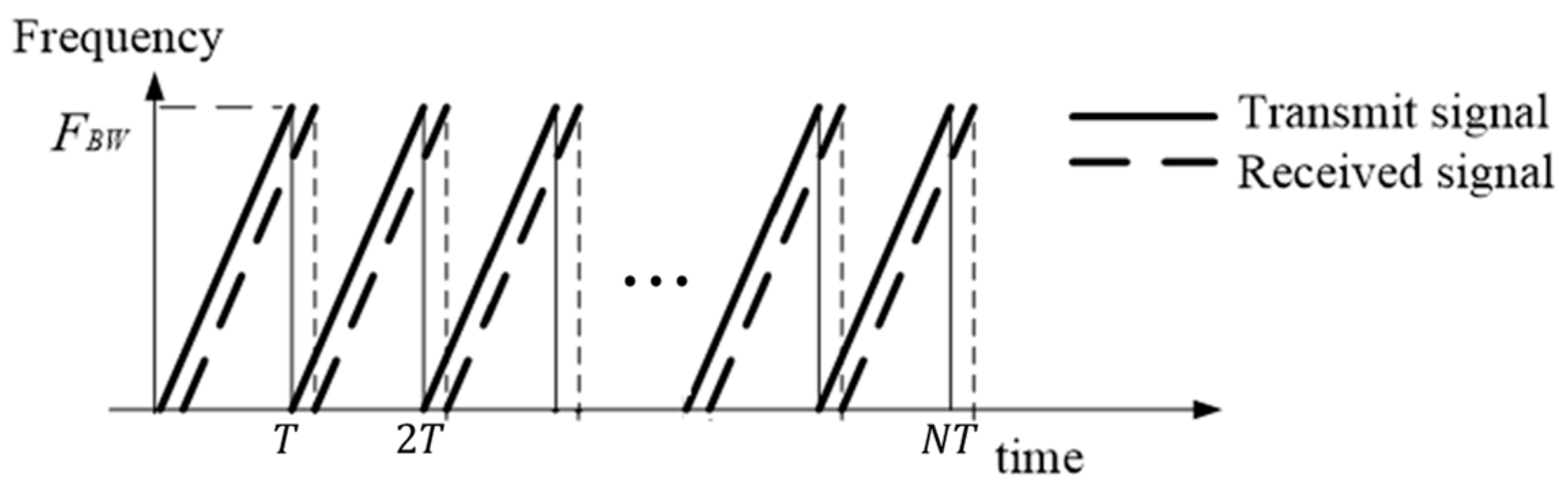
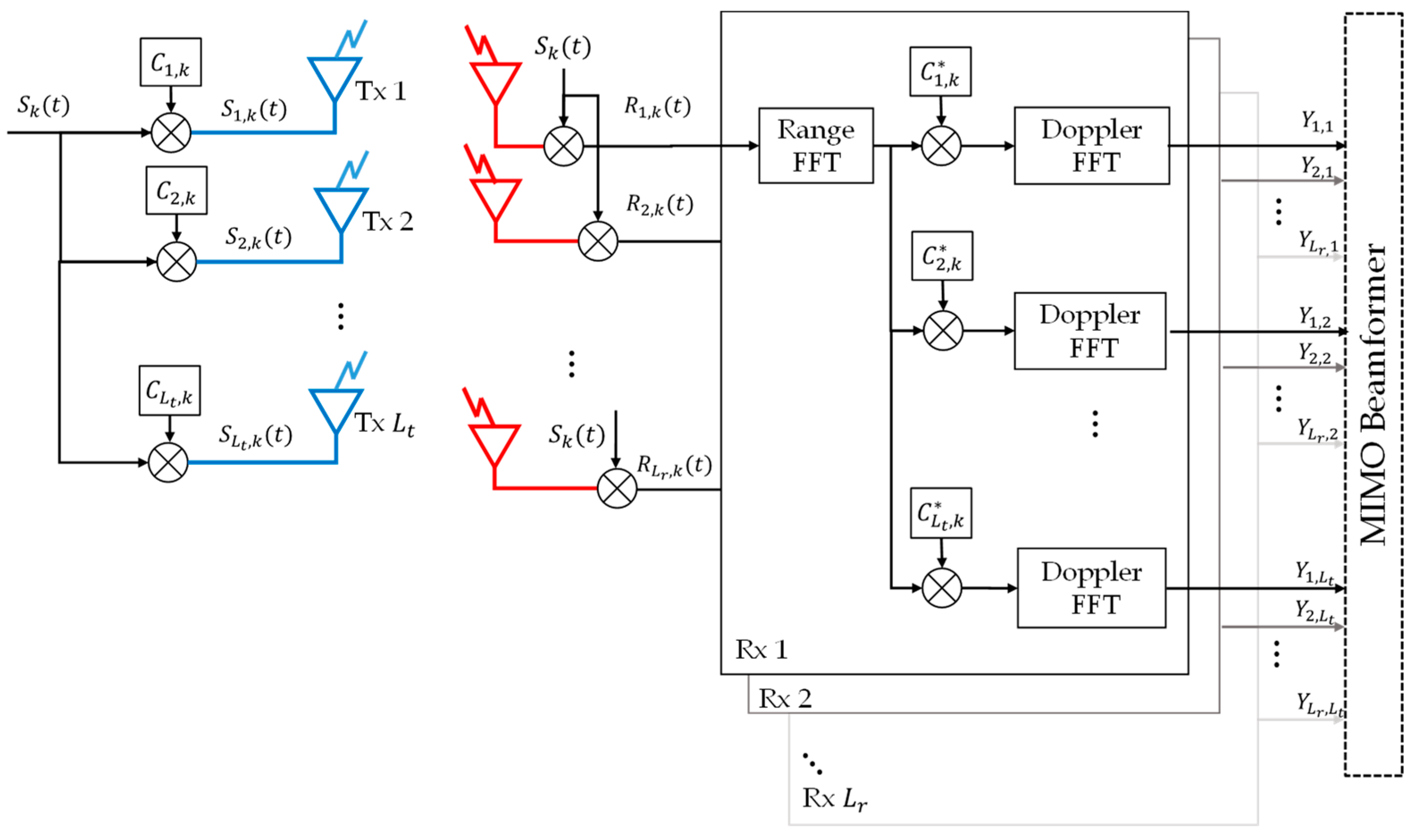
2.1. MIMO FMCW
2.2. Design of the Doppler-Insensitive Polyphase Code
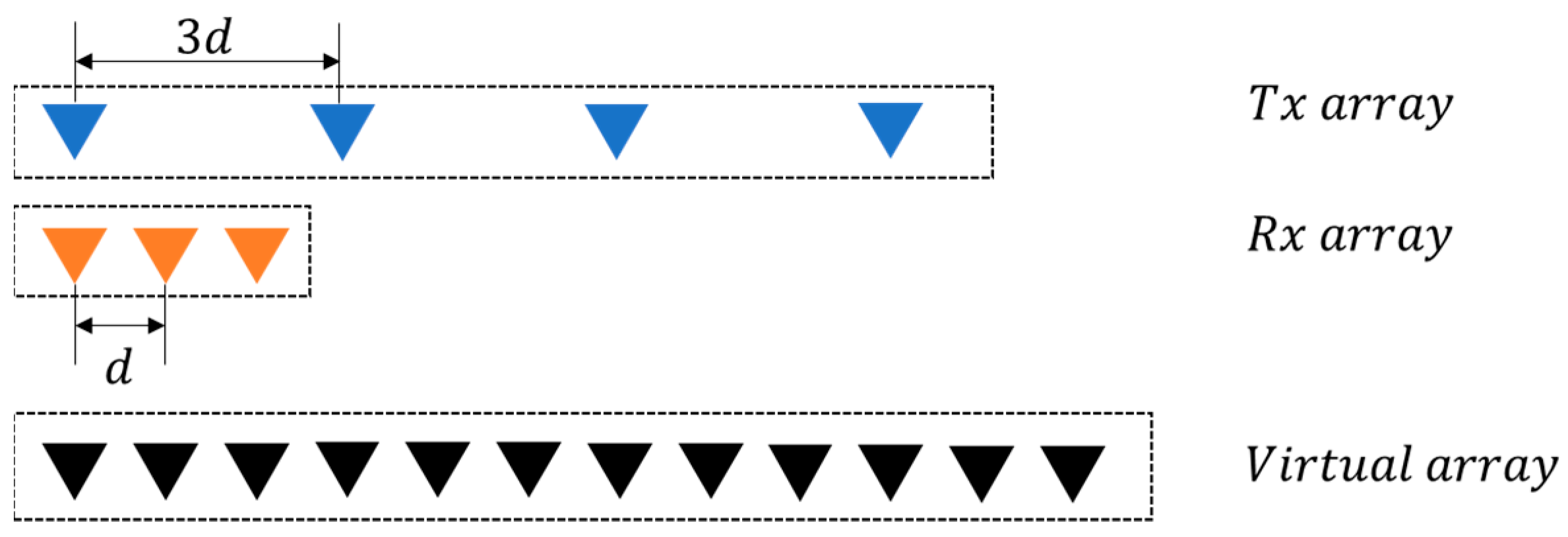
2.3. MIMO VAA
3. Simulation Results
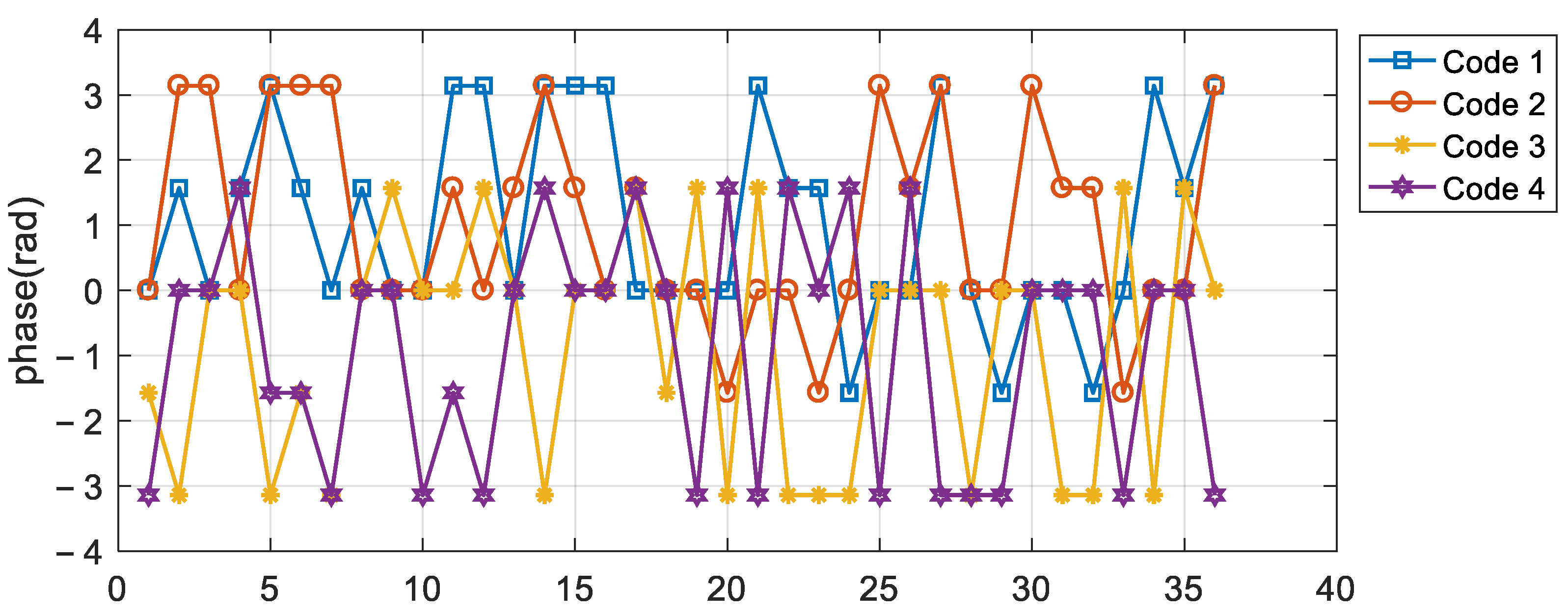
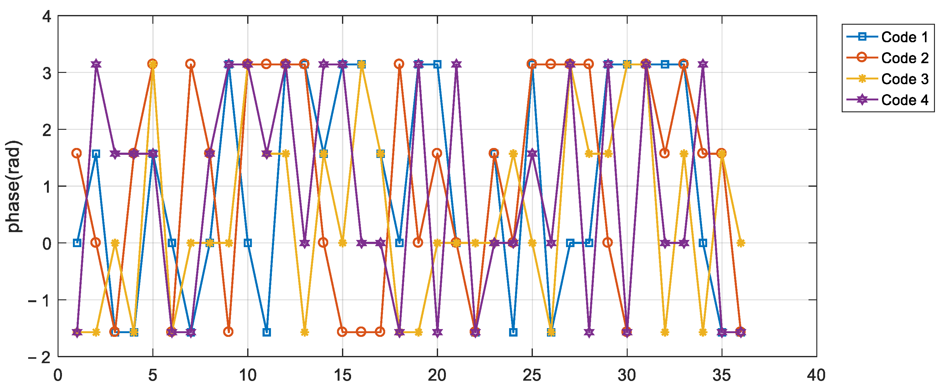
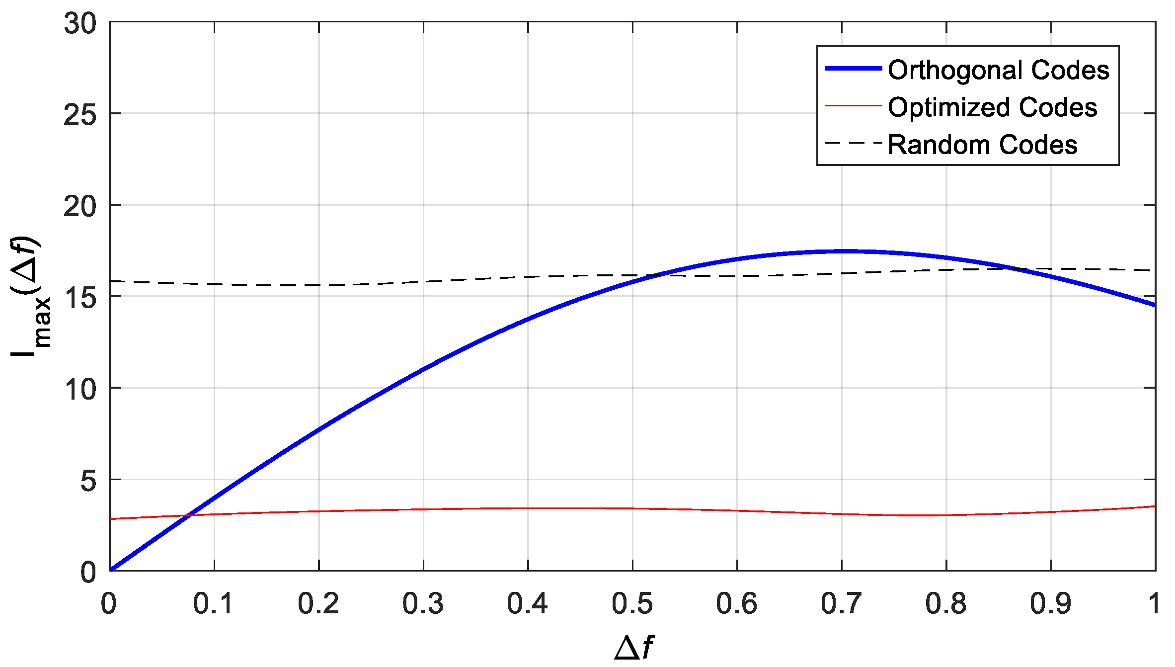
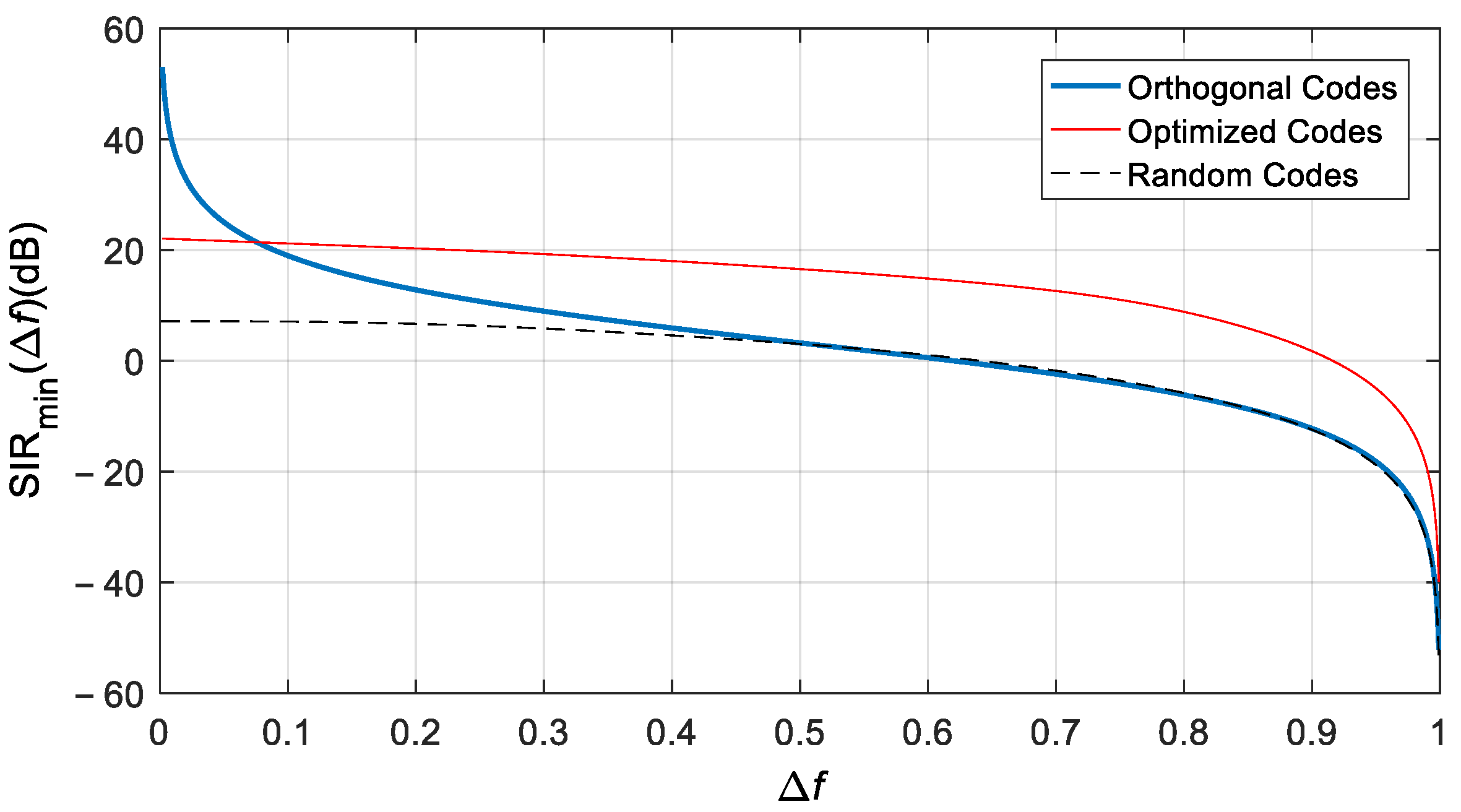
3.1. Doppler-Insensitive Code Design (36 Length, 4 Transmitters)
3.2. Performance according to M
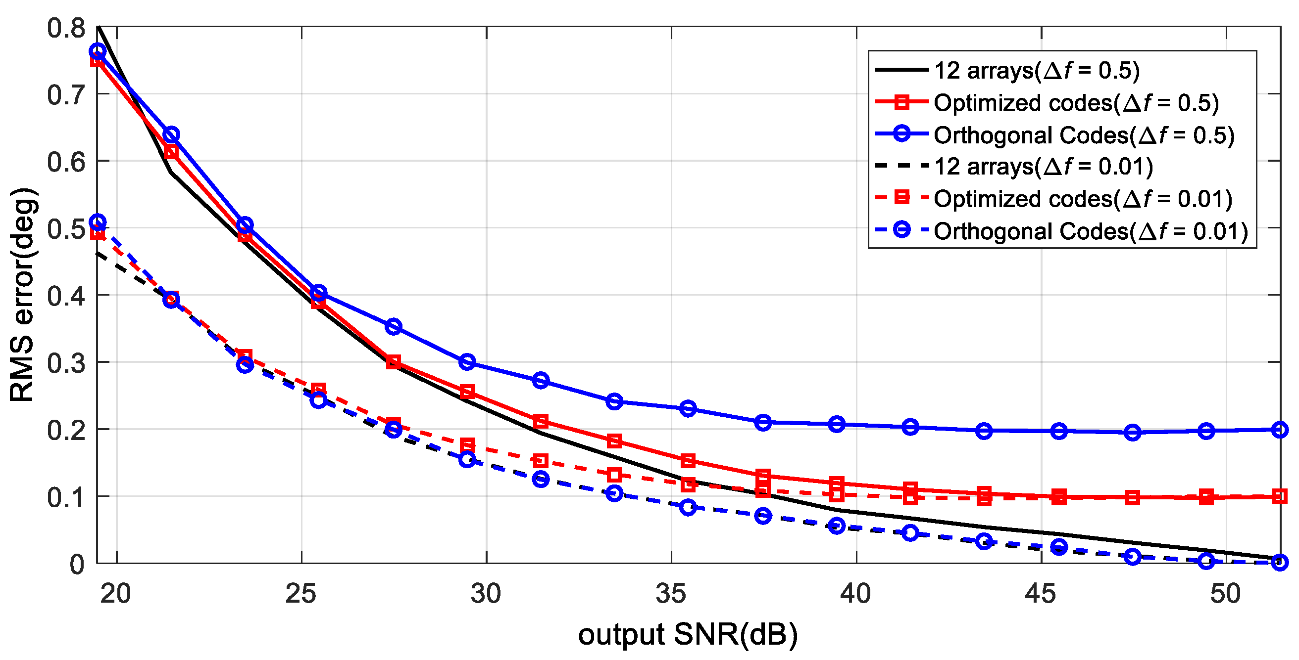
3.3. FMCW Simulation and MIMO Angle Accuracy
4. Conclusions
Funding
Data Availability Statement
Conflicts of Interest
Appendix A
References
- Kim, E.; Kim, K. Random phase code for automotive MIMO radars using combined frequency shift keying-linear FMCW waveform. IET Radar Sonar Navig. 2018, 12, 1090–1095. [Google Scholar] [CrossRef]
- Schmidt, R.O. Multiple emitter location and signal parameter estimation. IEEE Trans. Antenna Propag. 1986, 1, 276–280. [Google Scholar] [CrossRef] [Green Version]
- Rao, B.D.; Hari, K.S. Performance analysis of root-MUSIC. IEEE Trans. Acoust. Speech Signal Process. 1989, 37, 1939–1949. [Google Scholar] [CrossRef]
- Roy, R.; Kailath, T. ESPRIT—Estimation of signal parameters via rotational invariance techniques. IEEE Trans. Acoust. Speech Signal Process. 1989, 37, 984–995. [Google Scholar] [CrossRef] [Green Version]
- Li, J.; Li, D.; Zhang, Z. Extended-aperture unitary root MUSIC-based DOA estimation for coprime array. IEEE Commun. Lett. 2018, 22, 752–755. [Google Scholar] [CrossRef]
- Kay, S.M. Fundamentals of Statistical Signal Processing: Estimation Theory; Prentice Hall: Englewood Cliffs, NJ, USA, 1993. [Google Scholar]
- Sun, S.; Petropulu, A.P.; Poor, H.V. MIMO radar for advanced driver-assistance systems and autonomous driving: Advantages and challenges. IEEE Signal Process. Mag. 2020, 37, 97–117. [Google Scholar] [CrossRef]
- Frischen, A.; Hasch, J.; Waldschmidt, C. A cooperative MIMO radar network using highly integrated FMCW radar sensors. IEEE Trans. Microw. Theory Tech. 2017, 65, 1355–1366. [Google Scholar] [CrossRef]
- Han, K.; Hong, S. Detection and localization of multiple humans based on curve length of I/Q signal trajectory using MIMO FMCW radar. IEEE Microw. Wirel. Compon. Lett. 2021, 31, 413–416. [Google Scholar] [CrossRef]
- Wang, W.Q. Large time-bandwidth product MIMO radar waveform design based on chirp rate diversity. IEEE Sens. J. 2014, 15, 1027–1034. [Google Scholar] [CrossRef]
- He, H.; Stoica, P.; Li, J. Designing unimodular sequence sets with good correlations: Including an application to MIMO radar. IEEE Trans. Signal Process. 2009, 57, 4391–4405. [Google Scholar] [CrossRef]
- Sun, H.; Brigui, F.; Lesturgie, M. Analysis and Comparison of MIMO Radar Waveforms. In Proceedings of the 2014 International Radar Conference, Lille, France, 13–17 October 2014; pp. 1–6. [Google Scholar]
- Deng, H.; Geng, Z.; Himed, B. MIMO Radar Waveform Design for Transmit Beamforming and Orthogonality. IEEE Trans. Aerosp. Electron. Syst. 2016, 52, 1421–1433. [Google Scholar] [CrossRef]
- Li, J.; Stoica, P. MIMO radar with colocated antennas. IEEE Signal Proces. Mag. 2007, 24, 106–114. [Google Scholar] [CrossRef]
- Geng, Z. Evolution of netted radar systems. IEEE Access 2020, 8, 124961–124977. [Google Scholar] [CrossRef]
- De Wit, J.J.M.; Van Rossum, W.L.; De Jong, A.J. Orthogonal waveforms for FMCW MIMO radar. In Proceedings of the Radar Conference (RADAR) 2011 IEEE, Kansas City, MO, USA, 23–27 May 2011; pp. 686–691. [Google Scholar]
- Basit, A.; Khan, W.; Khan, S.; Qureshi, I. M, Development of frequency diverse array radar technology: A review. IET Radar Sonar Navig. 2018, 12, 165–175. [Google Scholar] [CrossRef]
- Huang, J.; Tong, K.F.; Woodbridge, K.; Baker, C. Frequency diverse array: Simulation and design. In Proceedings of the IEEE Radar Conference 2009, Pasadena, CA, USA, 4–8 May 2009; pp. 1–4. [Google Scholar]
- Texas Instrument. MIMO Radar; Application Report SWRA554; Texas Instrument: Dallas, TX, USA, 2017. [Google Scholar]
- Rohling, H.; Meinecke, M.M. Waveform design principles for automotive radar systems. In Proceedings of the 2001 CIE International Conference on Radar, Beijing, China, 15–18 October 2001; pp. 1–4. [Google Scholar]
- Tang, B.; Tuck, J.; Stoica, P. Polyphase waveform design for MIMO radar space time adaptive processing. IEEE Trans. Signal Process. 2020, 68, 2143–2154. [Google Scholar] [CrossRef]
- Deng, H. Polyphase code design for orthogonal netted radar systems. IEEE Trans. Signal Process. 2004, 52, 3126–3135. [Google Scholar] [CrossRef]
- Kirkpatrick, S.; Gelatt, C.D., Jr.; Vecchi, M.P. Optimization by simulated annealing. Science 1983, 220, 671–680. [Google Scholar] [CrossRef] [PubMed]
- Kim, E.H.; Kim, S.B.; Han, S.S.; Shin, S.J.; Oh, S.R. Design of polyphase codes using simulated annealing. J. Korean Inst. Electromagn. Eng. Sci. 2020, 31, 383–393. [Google Scholar] [CrossRef]
- Kim, D.-H.; Kim, H.-J.; Lim, J.-H. Design of Optimized Coded LFM Waveform for Spectrum Shared Radar System. Sensors 2021, 21, 5796. [Google Scholar] [CrossRef] [PubMed]
- Mahafza, B.R. Radar Systems and Design Using MATLAB, 3rd ed.; CRC Press: Boca Raton, FL, USA, 2013. [Google Scholar]
- Geramita, A.V.; Seberry, J. Orthogonal Designs: Quadratic forms and Hadamard Matrices; Lecture Notes in Pure and Applied Mathematics Series; Marcel Dekker Inc.: New York, NY, USA, 1970. [Google Scholar]


| Step | Description |
|---|---|
| 0. |
|
| 1. |
|
| 2. |
|
| 3. |
|
| 4. |
|
| 5. |
|
| 6. |
|
| 7. |
|
| 8. |
|
| 9. |
|
| Parameter | Value |
|---|---|
| 77 (GHz) | |
| 1 (GHz) | |
| 30 (usec) | |
| 4 | |
| 3 | |
| 64 | |
| 4 | |
| 50 (MHz) | |
| Target velocity | |
| Initial target distance | 40 (m) |
| Array interval |
Publisher’s Note: MDPI stays neutral with regard to jurisdictional claims in published maps and institutional affiliations. |
© 2022 by the author. Licensee MDPI, Basel, Switzerland. This article is an open access article distributed under the terms and conditions of the Creative Commons Attribution (CC BY) license (https://creativecommons.org/licenses/by/4.0/).
Share and Cite
Kim, E. MIMO FMCW Radar with Doppler-Insensitive Polyphase Codes. Remote Sens. 2022, 14, 2595. https://doi.org/10.3390/rs14112595
Kim E. MIMO FMCW Radar with Doppler-Insensitive Polyphase Codes. Remote Sensing. 2022; 14(11):2595. https://doi.org/10.3390/rs14112595
Chicago/Turabian StyleKim, EunHee. 2022. "MIMO FMCW Radar with Doppler-Insensitive Polyphase Codes" Remote Sensing 14, no. 11: 2595. https://doi.org/10.3390/rs14112595
APA StyleKim, E. (2022). MIMO FMCW Radar with Doppler-Insensitive Polyphase Codes. Remote Sensing, 14(11), 2595. https://doi.org/10.3390/rs14112595