Article

Attitude Determination for GRACE-FO: Reprocessing the Level-1A SC and IMU Data

1
MOE Key Laboratory of Fundamental Physical Quantities Measurement & Hubei Key Laboratory of Gravitation and Quantum Physics, PGMF and School of Physics, Huazhong University of Science and Technology, Wuhan 430074, China
2
Institute of Geophysics and PGMF, Huazhong University of Science and Technology, Wuhan 430074, China
3
Innovation Academy for Precision Measurement Science and Technology, Chinese Academy of Sciences, Wuhan 430071, China
*
Author to whom correspondence should be addressed.
Remote Sens. 2022, 14(1), 126; https://doi.org/10.3390/rs14010126
Submission received: 19 November 2021 / Revised: 15 December 2021 / Accepted: 21 December 2021 / Published: 28 December 2021

Abstract

:
The satellite gravity mission GRACE(-FO) has not yet reached its designed baseline accuracy. Previous studies demonstrated that the deficiency in the sensor system or the related signal processing might be responsible, which in turn motivates us to keep revising the sensor data processing, typically the spacecraft’s attitude. Many efforts in the past have been made to enhance the attitude modeling for GRACE, for instance, the latest release reprocesses the attitude by fusing the angular acceleration with the star camera/tracker (SC) measurements, which helps to reduce the error in Level-2 temporal gravity fields. Therefore, in addition to GRACE, revising GRACE-FO attitude determination might make sense as well. This study starts with the most original raw GRACE-FO Level-1A data including those from three SCs and one IMU (Inertial Measurement Unit) sensors, and manage to generate a new publicly available Level-1B attitude product called HUGG-01 covering from June 2018 to December 2020, using our independently-developed software. The detailed treatment of individual payload is present in this study, and an indirect Kalman filter method is introduced to fuse the multiple sensors to acquire a relatively stable and precise attitude estimation. Unlike the direct SC combination method with a predefined weight as recommended in previous work, we propose an involvement of each SC measurement in the Kalman filter to enable a dynamic weight adjustment. Intensive experiments are further carried out to assess the HUGG-01, which demonstrate that the error level of HUGG-01 is entirely within the design requirement, i.e., the resulting KBR pointing variations are well controlled within 1 mrad (pitch), 5 mrad (roll) and 1 mrad (yaw). Moreover, comparisons with the official JPL-V04 attitude product demonstrate an equivalent performance in the low-to-middle spectrum, with even a slightly lower noise level (in the high spectrum) than JPL-V04. Further analysis on KBR range-rate residuals and gravity recovery on January 2019 indicates that, i.e., RMS of the difference (HUGG-01 minus JPL-V04) for the range rate is less than 3.234 × 10 8 m/s, and the amplitude of geoid height difference is approximately 0.5 cm. Both differences are below the sensitivity of the state-of-the-art satellite gravity mission, demonstrating a good agreement between HUGG-01 and JPL-V04.

1. Introduction

The Gravity Recovery And Climate Experiment (GRACE) mission launched in March 2002 [1] and its successor GRACE-FO (follow-on) mission launched in May 2018 [2], have made great contributions to understanding climate change [3,4]. The monthly gravity fields [5] mapped by these gravity missions are widely used for studying, i.e., continental water [6,7,8], glacier mass balance [9,10], and even earthquakes of large scale [11,12].
However, the designed mission baseline accuracy for GRACE(-FO) has not yet been achieved [13,14]. Numerous simulation studies (see [15]) analyzed the GRACE’s error budget and concluded two major contributors as follows. The first one is the imperfect or mis-modeled background model, typically the ocean tide model and AOD (high-frequency non-tidal Atmosphere and Ocean De-aliasing) model [16,17,18]. Another contributor comes from the deficiencies in the onboard sensor system as well as the related signal processing, typically the inter-satellite ranging system and accelerometers [19,20], and both of them are relevant to the attitude information. We can not expect a better gravity field mapping by the current and future gravity mission unless the two limiting error sources mentioned above are well handled [15]. Recent researches find that the mis-modelling error in the background models might be considerably mitigated in the next generation gravity mission (NGGM, see [21,22,23]), through a unique design of the satellite constellation like Bender-type that enables co-estimating the background model parameters in a higher frequency [24,25]. However, the error due to sensor data processing deficiency is non-relevant to the constellation, and will remain as a problem even for the NGGM. In this context, keeping revising the sensor data processing strategy (Level-1A to Level-1B) is necessary, otherwise, the high-accuracy payload like K-Band Ranging (KBR, ∼1 um) system or even the substantially improved Laser Ranging Interferometry (LRI, ∼1 nm, see [26]) system might be a waste of resources. Among these, precise attitude determination is one of the most challenging tasks [20].
Seen from history, every evolution of the Level-1B product does achieve the aim to improving the quality of Level-2 gravity fields, e.g., the accuracy is dramatically enhanced by ∼10 times from gravity model RL01 to RL06 [27]. As recorded, the official Level-1B product has gone through several updates from V00 to V04 since 2002. The efforts related to these updates are dedicated to revise/reprocess, for instance (not limited to), the attitude, the accelerometer alignment, the KBR antenna phase center location, orbit determination, and clock solutions (see [20,28,29,30]). Among these, the attitude information is especially particular, since it is essential for the processing of the K-band ranging data, the accelerometer data, and even other force models (i.e., gravitational background models) that act on the satellites [14]. Efforts are therefore ongoing to refine the attitude, expecting to acquire an overall accuracy improvement of the temporal gravity field. For instance, Frommknecht [19], Bandikova et al. [31] made an overall analysis of the star tracker/camera (SC) measurements (that are used to compute the attitude) and outlines their error level. Furthermore, Inácio et al. [32] developed a noise model for SCs and analyzed their impact on monthly gravity field models. Based on previous experience, Harvey [33] proposed a correction to SCs, which eliminated a several-arcsec twice-per-rev error with daily modulation. One step further, leveraging the a-priori error information of SCs, Chen et al. [34] improved the monthly gravity field solution by co-modeling the attitude observation errors. Recently, Goswami et al. [14] firstly reveals the possibility to enhance attitude determination with steering mirror data aside from SCs.
Apart from investigating the SC’s error behaviors, the algorithm to determine the attitude is also a focus of recent researches. It is worth mentioning that, the official algorithm used for attitude determination priori to V03 accounts for only the SC measurements (for GRACE), so that the combination of two SC heads are therefore essential [35]. Unlike the official combination method in terms of a weighting matrix that considers the anisotropic accuracy of each SC, Bandikova and Flury [20] proposed to merge only the well-determined SC boresight directions, and in this way, an equivalent performance is achieved. Despite the combination, the SC has its inherent flaw, that is, SCs are occasionally blinded by Sun/Moon in the vicinity of the Sun/Moon intrusions and therefore are less reliable or even unavailable in this case [19]. To remedy the gaps/discontinuities due to the regular blinding, a numerical interpolation has to be done to extend the attitude time series, with a price of inevitable deterioration propagated into the ultimate temporal gravity fields [29]. In this context, a Kalman filter-based strategy is proposed to fuse SCs and angular acceleration measurements to reconstruct spacecraft attitude with reduced high-frequency noise and fewer gaps (see [36,37]). Goswami et al. [38] revealed a significant improvement in the attitude due to the reprocessed (fused) product and reduced value of K-band ranging residuals computed from the reprocessed attitude. Subsequently, such a Kalman filter-based strategy has been adopted by the official data processing center since V03. Besides, the recovered GRACE gravity field from the V03 data set demonstrates a substantially damped systematic noise during early and late mission [36].
As an official algorithm of GRACE, the Kalman filter/fusion is applied to GRACE-FO as well [39], whereas the only difference is a replacement of angular acceleration with angular velocity in the fusion. This is because the onboard (GRACE-FO) payload IMU (Inertial Measurement Unit) can directly measure angular velocity, so that the less reliable angular acceleration acquired from the accelerometers is not required anymore. According to GRACE-FO’s official document [39,40], the attitude reconstruction is made by following two steps: (i) three SC head units are combined first in a fixed weighting matrix like the way mentioned before, and subsequently (ii) the combination result is delivered into Kalman filter to accomplish the fusion with IMU measurements. Nevertheless, this study finds that the pre-combination of SCs indicated by step (i) is indeed unnecessary. In other words, a more elaborate method might be to conduct both the SCs and IMU measurements inside one process, e.g., Kalman filter, which is also suggested by Frommknecht [19]. Compared to the fixed weighting matrix used in the official method, the new option allows for a data-driven weight adjustment between three SCs, so that any other perhaps unknown effects deteriorating the SC quality could be considered. This new option proposed by this study will be carried out to reprocess the Level-1A data and generate a new attitude product. In addition, the processing of the SC and IMU from Level-1A to Level-1B requires not only data combination and Kalman filter, but also the rotation from the inertial frame into science reference frame, discarding of invalid data, sign flip, application of time tag correction, low-pass filter, and interpolation, etc. [29,31]. However, none of the details related to these steps have been explicitly discussed to date. This study would verify the critical steps and analyze the possible error that might be introduced by the corresponding step. We hope, in this way, to deepen the understanding of attitude reconstruction.
In Section 2, the data used for the study is briefly outlined. Section 3 introduces the mathematics behind each step required for the attitude reconstruction. In Section 4, the experimental results of our attitude product are demonstrated for the critical steps. Section 5 makes a thorough assessment of our attitude product by comparison with the official one. Section 6 concludes our findings and remaining open issues for future work.

2. Data

Since the study is tailored to the attitude reconstruction of GRACE-FO, GRACE Level-1A (or 1B) data set is not relevant. In this sense, all the phrases ‘Level-1A (or 1B)’ that appeared below are denoting the case of GRACE-FO V04 unless a particular statement. We note that all the input data involved in this work are publicly available in ftp://isdcftp.gfz-potsdam.de/grace-fo/ (accessed on 9 November 2021), and their detailed definitions refer to Wen et al. [39].
For a better understanding, we classify the employed data into two types according to their usages. The first type is the raw Level-1A data set which is regarded as the input (starting point) of the whole computation. It includes SCA1A, IMU1A, and auxiliary data. SCA1A records the attitude measurements of three SC head units at a frequency of 2 Hz, in the form of quaternions expressed in each of the three SCF (Star Camera Frame). IMU1A records four angles rotated from each of the gyro axes at a frequency of 8 Hz. The auxiliary data contains QSA1B, TIM1B, CLK1B files. QSA1B records the rotation from SCF into SRF (Science Reference Frame), in the form of quaternions for each SC head unit. Notice that QSA1B is a result of pre-calibration on the ground for GRACE-FO, while GRACE provides additionally the calibration result on the orbit. TIM1B and CLK1B provide the corresponding time tag correction for GPS time conversion. With all these data prepared well, a fused attitude product for any given day can be produced.
The second type is the data set for the purpose of verification, comparison, or assessment. SCA1B is the official fused attitude product that is used for comparison. GNI1B records the trajectory states in an inertial frame, which can be used to calculate the LOS (Line-Of-Sight) frame associated with VKB1B (Vector offset for KBR antenna) file. LOS is necessary because the performance of the attitude product is more prone to be analyzed under the LOS frame. At last, other official Level-1B data sets are required for studying the attitude’s influence on the range-rate residuals and eventually the gravity field recovery [41,42]. Generally, the Level-1B data includes GNV1B (trajectory states in Earth-fixed frame), ACC1B (accelerometer measurements), KBR1B (K-band ranging/ranging rate/ranging acceleration), and LRI1B (Laser-interferometry ranging/ranging rate/ranging acceleration). At last, the Level-2 temporal gravity fields from CSR-RL06 are used as a reference.

3. Method

Besides the SCs measurement (the only attitude sensor for GRACE), GRACE-FO provides an additional possibility, IMU, to monitor the spacecraft’s orientation. In this section, we focus on the SC and IMU processing method from Level-1A to Level-1B, as well as their combination method to achieve the final attitude determination. To ease the understanding, the overall processing procedures are briefly outlined in Figure 1, which divides the whole scheme into three stages: (1) IMU processing, (2) SC processing, and (3) data fusion.

3.1. IMU Processing

The GRACE-FO IMU consists of 4 fiber optic gyroscopes in tetrahedral configuration [39], which records the filtered angle in individual gyro frames at a sampling rate 8 Hz. As the starting point of the IMU processing is Level-1A, this section mainly discusses the IMU1A product.
The time system tagged for IMU1A is the receiver time, which is serviced by USO (Ultra-Stable Oscillator), so that a time-tag correction is essential to ensure all measurements in a unified time system, i.e., GPS time. The official TIM1B and CLK1B provide the route to achieve the conversion from the receiver time to GPS time. Specifically, TIM1B is used to convert OBC (Onboard Computer) time into the receiver time, and CLK1B converts the receiver time to GPS (Global Position System) time. Nevertheless, as both TIM1B and CLK1B are given in a discrete form, an interpolation of these time data is required to assure an exact point-to-point correspondingly time conversion. There might be many choices for the interpolation, of which we select the cubic spline interpolation that is found to be sufficient, see the experimental result in Section 4.1.
Subsequently, the conversion from the filtered angle θ to the angular velocity ω is required, since the angular velocity ω is the entry for the attitude reconstruction (Kalman filter). This can be achieved through a numerical differential method, with a simplest assumption that ω k at k’th epoch is constant over the integration period Δ t = t k + 1 t k , thus making the differential equation linear time invariant as below,
ω k = θ k + 1 θ k t k + 1 t k .
We call this method as a ‘POST’ method, since it uses the epoch after the one to be solved to derive the velocity. As a contrary, there is another method called ‘PRE’, which employs the epoch before the one to be solved, in the form of
ω k = θ k 1 θ k t k 1 t k .
Nevertheless, this study utilizes an average turn rate ω ¯ of Equations (1) and (2) to enable a more smooth differential, which is called ’MID’. Three methods (POST, PRE and MID) are compared with each other in Section 4.1. In addition, it is also worth mentioning that, during the differential a few discontinuities are found and require to be eliminated. They happen when gyro angle adjusts itself to restart at 5758 degree once it exceeds −5758 degree, or vice versa.
The last step is a transformation of the angular velocity from the gyro axis into the IMU frame, and eventually the SRF frame that is the adopted reference coordinate for the final attitude product, see Section 2. It is worth mentioning that, prior to the transformation, an interpolation of the angular velocity is required, since the time-tagged of the four fiber-optic gyroscopes (denoted as ω 1 , ω 2 , ω 3 , ω 4 ) is out of sync. The cubic spline interpolation is thus employed to keep time synchronization. The 8 Hz raw data is then resampled in a uniform distribution as [0, 0.125, 0.25, 0.375, 0.5, 0.625, 0.75, 0.875] s. After that, we proceed to the coordinate transformation from the gyro axis to the IMU frame. Original measurements in the gyro axis are obtained from four sensors, while the target in the IMU frame is an orthogonal vector that consists of only three elements [ ω x , ω y , ω z ] . Such a redundant configuration well improves the accuracy of acquired information [43] through solving the least square solution as
[ ω x , ω y , ω z ] T = ( H T H ) 1 H T [ ω 1 , ω 2 , ω 3 , ω 4 ] T ,
where design matrix H 4 × 3 denotes the frame rotation matrix composed of four gyroscope’s pointing vectors, which are constant and can be directly obtained from the record in Wen et al. [39]. In order to investigate the advantage of the redundancy, we compare the four-sensors strategy of Equation (3) with the three-sensors strategy (using only three out of the four sensors), see the results in Section 4.1. At last, [ ω x , ω y , ω z ] are transformed into the ones in the SRF frame by leveraging the rotation matrix recorded in Wen et al. [39].

3.2. SC Processing

GRACE-FO is equipped with three-star cameras (SCs), which are rigidly mounted to the accelerometer cage and their optical axis oriented towards the direction of the port panel, starboard panel, and zenith panel of the satellite to measure the position of the spacecraft’s attitude in the inertial frame. SCs are subject to regular blinding by the sun and moon, but a reasonable arrangement of SCs can prevent/reduce the discontinuity of attitude information. Compared to GRACE (only two SCs), the configuration of three SCs in GRACE-FO has nearly no discontinuities anymore. SCs measurements are recorded in SCA1A files, where we begin the discussions.
Like the IMU processing, the first thing to be dealt with is the time-tag correction. Nevertheless, this step is nothing different from the one discussed in Section 3.1, so we do not repeat. The very particular ones of SCA1A processing include outlier removal, sign flip, quaternion interpolation, and frame transformation. The theory of the quaternion algebra is the basis of SC processing, which refers to e.g., Trawny and Roumeliotis [44]. The outlier removal is conducted at two stages, of which the first stage tells and removes the outliers through the quality flag recorded in SCA1A file, for example, whose value 6 . Most distinct outliers can be eliminated in this way. However, some hidden outliers might still exist, which can be further distinguished at the stage of the SC combination that will be discussed later on.
Sign flip is another prominent problem found in SCA1A data, manifesting as a sudden reversion of the quaternion’s sign. This situation can be identified and solved by always comparing the current quaternion measurements Q k ( Q = [ q . x , q . y , q . z , q . w ] ) to its previous one Q k 1 . The imaginary or the vector part q ¯ = [ q . x , q . y , q . z ] of the quaternion Q represents the rotation direction, and we assume that the directions inferred from two neighbor epochs should not change rapidly. Thus, the sign of Q k should be reversed if
q ¯ k · q ¯ k 1 0 .
A sequential operation with Equation (4) sliding along the time series is carried out in this study, and the problem of sign flip can be well solved then. One may pose a question on that, quaternion Q and Q express the same rotation. Nevertheless, sign flip will affect the quaternion interpolation, so that this operation is still necessary.
Time synchronization is always an important issue throughout the work, i.e., between SCs, since each payload works independently. In this case, the original 2 Hz SCA1A has to be interpolated/resampled into [0, 0.5] s for each SC. Since Slerp and Squad methods are among the most general choices for quaternion interpolation, both are adopted in this study to investigate the influence of the interpolation method. Basically, Slerp method is a spherical linear interpolation, following
S l e r p Q 0 , Q 1 ; t = sin 1 t θ sin θ Q 0 + sin t θ sin θ Q 1 ,
where t denotes the epoch to be interpolated, [ Q 0 , Q 1 ] denotes the quaternions at the endpoints of the interpolation time, and θ is the rotated angle between the vector part of Q 0 and Q 1 , which gives
θ = cos 1 ( q ¯ 0 · q ¯ 1 ) .
Rather than a linear interpolation, Squad (Spherical quadrangle interpolation) is known as a spline-based (cubic) interpolation of rotations (unit quaternion), which therefore is smoother and better preserves the angular velocity than Slerp. Implementation of Squad is simple, through repeating the Slerp interpolation a few times, following
S q u a d Q 0 3 ; t = S l e r p S l e r p Q 0 , Q 3 ; t , S l e r p Q 1 , Q 2 ; t ; 2 t t 1 ,
where [ Q 0 3 ] denotes four quaternions labelled with [ Q 0 , Q 1 , Q 2 , Q 3 ] at nearby epochs, since at least four points are needed to fulfill the cubic-like interpolation. Performance of Squad and Slerp are assessed in Section 4.2.
The last step is the coordinate transformation of SCA data from SCF to SRF. This is easily achieved by extracting the quaternion (represents the rotation matrix) from the QSA1B file, or SOE file. Previous studies have found the SCA accuracy of rotation about the direction perpendicular to the boresight is about a factor of 8 10 better than rotation about the boresight. And after the coordinate transformation, the anisotropy (only one direction is bad) of the attitude in a frame of SCF will inevitably lead to a worse anisotropy of the attitude ( Y S R F and Z S R F are contaminated) in SRF. Combining quaternions simultaneously from differently aligned SCs might reduce this anisotropy [14]. At present, two methods are commonly used for the combination. The first one is based on weighted information according to the anisotropic noise [35]. The second one is building the common reference frame by merging the boresight axes [45]. These methods have been successfully applied to CHAMP, GRACE, GRACE-FO, and GOCE attitude processing [20,35,46,47]. In particular, the weighted combination method provided by Romans [35] is preferred in this study, following
Q I C o p t = Q I C m e a s ( 1 ) 1 , 1 2 Λ ˜ t o t 1 α 1 Λ ˜ α Δ 1 α ,
where notation ⊗ denotes the quaternion multiplication, I denotes an inertial frame, C is the common reference frame such as the SRF for the case of GRACE/GRACE-FO. Q I C m e a s ( 1 ) is the measurement of arbitrary one of the three SCs, which is defined as No.1 by convention. Δ 1 α represents the offset between the No.1 SC measurement and another one labelled with α . The offset Δ 1 α is derived according to
Q I C m e a s ( 1 ) 1 Q I C m e a s ( α ) = ( 1 , 1 2 Δ 1 α ) .
Besides, Λ ˜ in Equation (8) denotes the weighting matrix for certain SC sensor (No. α ) or the total of all SCs, for instance, Λ ˜ t o t = α Λ ˜ α . The weighting matrix Λ ˜ α can be determined from the covariance matrix (representing the anisotropy) of the SC following
Λ α = 1 σ α 2 1 1 1 κ 2 ,
where σ α represents the overall noise level of the SC about the boresight axes, whereas the ratio factor κ denotes the anisotropy. Empirically, κ is assigned with 8∼10, see Goswami et al. [14], Romans [35]. Equations (8)–(10) construct our basis of SCs combinations for GRACE-FO, and a corresponding experiment is conducted to verify its effect, see the details in Section 4.2. Leveraging the combination results and 3- σ criteria, we can further identify the outliers that are hardly distinguished in single SC. Nevertheless, the single SC measurement rather than the combination result is sent to our Kalman filter, since we think the Kalman filter has the ability to dynamically adjust the weighting between SCs.

3.3. Kalman Filter

SC and IMU are important payloads for precise attitude measurement on satellites. The SC is sensitive to the low-frequency of the satellite attitude, on the contrary, the IMU is sensitive to the high-frequency of the satellite attitude. Combining these two types of data can fully exploit their advantage and obtain high-precision attitude products better than any individual one of them.
The Kalman filter provides such a common frame for an optimal multiple data fusion. Generally, the Kalman filter consists of two stages, (1) state propagation and (2) state correction/update, to determine an estimate of the current attitude. IMU provides measurements of the translational rotation velocities acting on the system, which are used in this study to estimate the orientation as the dynamic model in the first stage (see [44]). In this sense, the only measurement in the phase of state update comes from SCs. Such an implementation completely follows the one proposed by Trawny and Roumeliotis [44] and Lefferts et al. [48], which is also called an indirect Kalman filter and is widely used for spacecraft attitude estimation. In what follows, the procedures are briefly outlined.
Firstly, a seven-element state vector consisting of the quaternion and gyro bias is defined as
x t = q t b t ,
where q ( t ) represents the quaternion of orientation that comprises four elements, and b ( t ) represents the gyro drift rate bias that comprises three elements (three directions). For gyro models, the spacecraft’s angular velocity ω is related to the gyro measurement μ ( t ) according to
ω ( t ) = μ ( t ) b ( t ) η 1 ( t )
d b d t = η 2
where the vector η 1 is the drift-rate noise assumed to be a Gaussian white-noise process. The drift rate bias b ( t ) is not constant but also subject to a second Gaussian white-noise process following Equation (13). The ‘true’ angular rate ω ( t ) can be obtained from Equation (12), and sent into the state equation to propagate the orientation following
q t + 1 | t = A ( ω ( t + 1 ) ) q t | t
P t + 1 | t = Φ P t | t Φ T + Q d ,
where P denotes the state covariance matrix, which is computed from the transition matrix Φ and the discrete time noise covariance matrix Q d . In particular, A ( ω ( t ) ) denotes a function of angular velocity ω ( t ) that can be used to predict the orientation in the next epoch q t + 1 | t , see its detailed formulas in Lefferts et al. [48]. With ω ( t + 1 ) and q t + 1 | t ready, the propagated state estimate x t + 1 | t is uniquely determined. Given the propagated state estimate x t + 1 | t associated with their covariance matrix P t + 1 | t , the current SC measurement z t + 1 , and the measurement matrix H (it is indeed an unity matrix if z t is given in SRF), we can further update (or correct) the estimation following
x t + 1 | t + 1 = x t + 1 | t + K t [ z t H t x t + 1 | t ]
P t + 1 | t + 1 = [ I K t H t ] P t + 1 | t ,
with the gain factor K t calculated from
K t = P t + 1 | t H t T [ H t P t + 1 | t H t T + R t ] 1 ,
where R t denotes the covariance of measurement noise. Please notice that, Equations (16)–(18) indicate a general update procedure using 7-elements state vector, whereas the seven elements are dependent (the norm of quaternion asks for being equal to one), which indeed violates the principle of Kalman filter. A more elaborate method that avoids the dependency should be reducing one redundant element from the state vector, please refer to Trawny and Roumeliotis [44]. A validation of the Kalman filter is carried out in Section 4.3.
The two inputs of the Kalman filter are respectively 8 Hz and 2 Hz, resulting in a final sampling rate of 8 Hz in the reconstructed attitude product. Therefore, the sampling rate requires to be reduced to keep in accordance with the 1 Hz JPL-V04 attitude product. To this end, we adopt the CRN low-pass filter to prevent the aliasing effect caused by the down-sampling, see the details in Frommknecht [19], Wang [49].

3.4. Metrics

The twin satellites’ attitude is vital for GRACE-FO K-band ranging system, as well as the gravity recovery, which in turn provides the metrics to make an evaluation of the attitude product’s quality through investigating the (1) inter-satellite pointing variation, (2) the range rate residual, and (3) recovered gravity field. The theory of gravity recovery is complicated but has been intensively discussed before, please refer to Dahle et al. [5].

3.4.1. Inter-Satellite Pointing Variation

The accuracy of the inter-satellite pointing has become a research topic recently, and the attitude is one of the factors that determine the quality of pointing [31]. The inter-satellite pointing can be geometrically interpreted as angular deviations between the KBR antenna phase center vector and line of sight (LOS) vector, which is the imaginary straight line between the two satellites’ center of mass. And these angular deviations (representing the pointing variation) derived from those including attitude product can somewhat infer the attitude’s accuracy, since the pointing variation is assumed to be smaller the better. Find more details and concepts on the definition in Bandikova et al. [31].
The inter-satellite pointing variation R K F L O S can be calculated as follows:
R K F L O S = R I L O S · R S R F I · R K F S R F ,
where R I L O S represents the rotation matrix from the inertial frame to the LOS, which can be calculated from the orbit data (GNI1B). R S R F I is the rotation matrix from the SRF to the inertial frame, which can be calculated from the attitude product (e.g., HUGG-01). R K F S R F represents the rotation matrix from the KF (K-frame maintained by the K-band ranging system) to SRF. KBR antenna phase center vector is required for computing KF, and can be found in SOE or VKB1B files. Notice that, the notation R in Equation (19) denotes the direction cosine matrix, which is one of the most usual representations of the 3D rotation, and can be transformed into Euler format that is more prone to be understood. Furthermore, Euler rotation factorizes the R K F L O S into three sequential sub-rotations: roll ( ψ ), pitch ( θ ) and yaw ( ϕ ) as follows:
R K F L O S = R 1 ψ R 2 θ R 3 ϕ .
Solving the Euler angles [ ψ , θ , ϕ ] from Equation (20) refers to Bandikova et al. [31]. The solved Euler angles are selected to assess the pointing variation derived from a given attitude product.

3.4.2. Inter-Satellite Range Rate Residual

The state-of-art gravity field solutions are computed from the K-band range-rate observations ( ρ ˙ ) which measures the tiny mass changes in the Earth, with a precision of μ m [38]. One of the error sources in gravity solution comes from the attitude information, which is critical for calculating the range-rate residual Δ ρ ˙ through the least square equation as
A x ^ = l e
where the x ^ to be estimated denotes the gravity model, and A is the associated design matrix. In particular, the observation l in the right side is just the so called range-rate residual Δ ρ ˙ . Computing Δ ρ ˙ follows
Δ ρ ˙ = ρ ˙ m e a s ρ ˙ n o m i n a l ,
where ρ ˙ m e a s denotes the direct range-rate measurement obtained from the payload, while ρ ˙ n o m i n a l is a nominal range-rate synthesized from the orbit propagated by the known forces, e.g., non-conservative force. The computation of these forces heavily rely on the attitude information to achieve the transformation into inertial frame, and in this sense, attitude’s precision will affect range-rate residual ρ ˙ m e a s in Equation (22) and further the gravity model x ^ in Equation (21). In this study, we directly select Δ ρ ˙ as an index to assess different attitude products. This method is also adopted by Goswami et al. [38] to analyze the attitude data for GRACE.

4. Analysis

The details related to the method discussed above will be analyzed with experiments in this section. Since GRACE-FO consists of twin satellites that follow each other in the orbit around the Earth, the payload of twin satellites has a similar work environment and behaves closely with each other. Therefore, we will only show the result of one satellite (either Sat-C or Sat-D) for the purpose of demonstration in the following.

4.1. IMU Processing

Time-tag correction is a mutual and critical step for IMU and SC processing so that verification is essential. Fortunately, the official IMU1B provides us the possibility to conduct such verification. We retrieve the corrected time-tag result from IMU1B and refer to it as the ground truth to perform the comparison with ours. Since the onboard IMU system consists of four-axis and each of them needs the time-tag correction, we summarize the comparison result of all four axes and give the statistical results (GRACE-FO satellite D) at Table 1. Besides, tests across one single day (1 January 2019 Sat-D of GRACE-FO) and one month (January 2019) are given to ensure a robust and reliable comparison. It can be seen from Table 1 that, the error introduced by time-tag correction is well controlled within 2 × 10 6 s, and statistically, the mean is 0.55 × 10 6 s, which is obviously below the rounding error of the data record itself ( 1 × 10 6 s). Such an error level has nearly no impact on the attitude determination (results not shown), demonstrating the rightness of our strategy of time-tag correction.
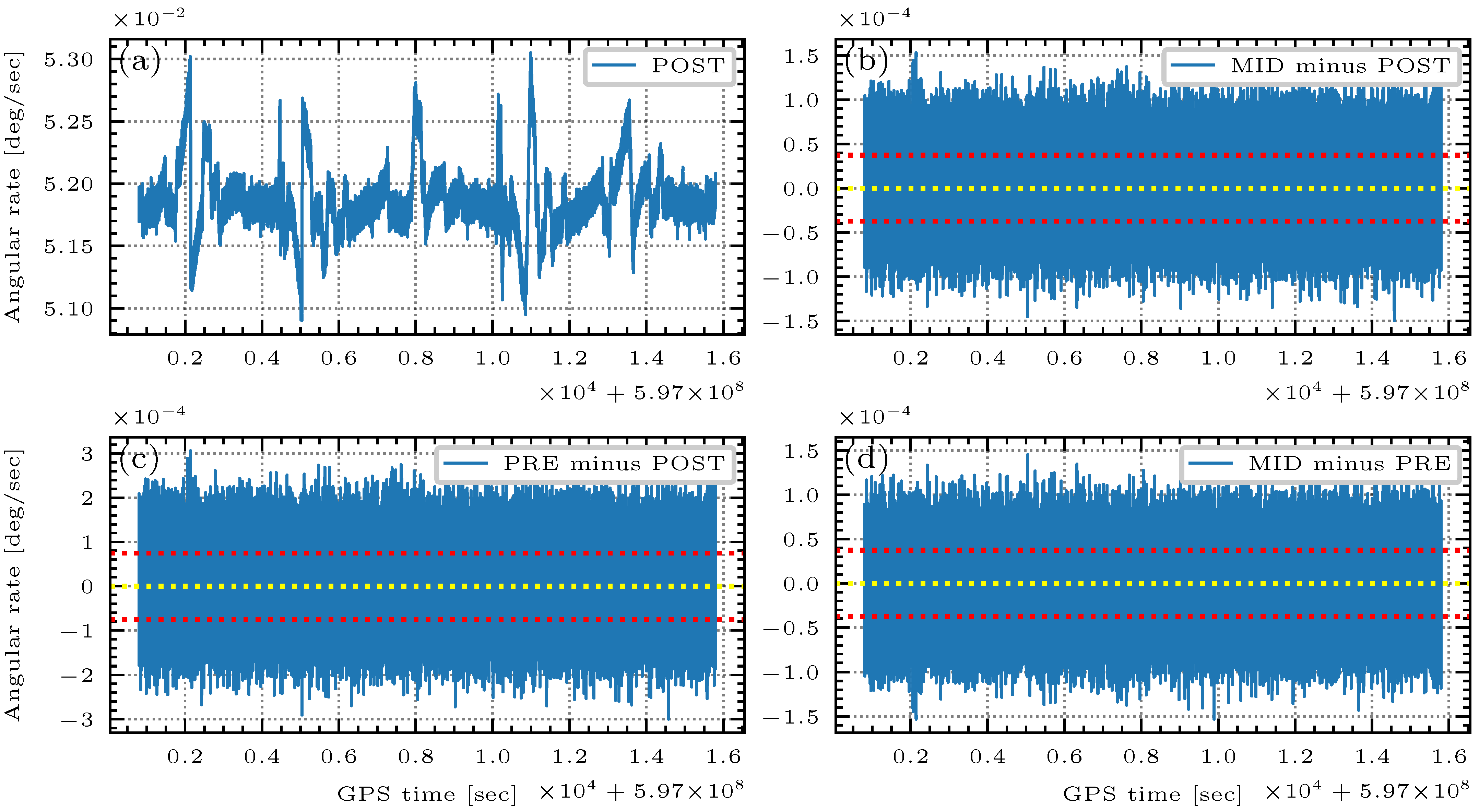
The general workflow of the Kalman filter asks for the corporation of angular velocity instead of the rotated angle provided by IMU1A, meaning that a conversion is required. The conversion is achieved through three differential algorithms denoting as PRE, MID, and POST, see Section 3.1. The differential method’s impact on computing angular velocities is investigated here, through plotting the differences between three methods (MID, POST, and PRE), see Figure 2b–d. All the differences are found to have an approximately zero-mean (in yellow dashed lines), implying that the three methods have no bias between each other. Nevertheless, 1-sigma value (in red dashed lines) of the differences ranges from 4.1 × 10 5 to 9.1 × 10 5 , which takes up 2∼4% of the angular velocity amplitude (approximately 2 × 10 3 , see Figure 2a). However, based on solely Figure 2, it is hard to assert whether such a magnitude of the differences (2∼4%) between the demonstrated three differential methods is negligible or not. Therefore, we leave this issue in the Kalman filter to investigate its impact on the attitude determination, see Section 4.3.
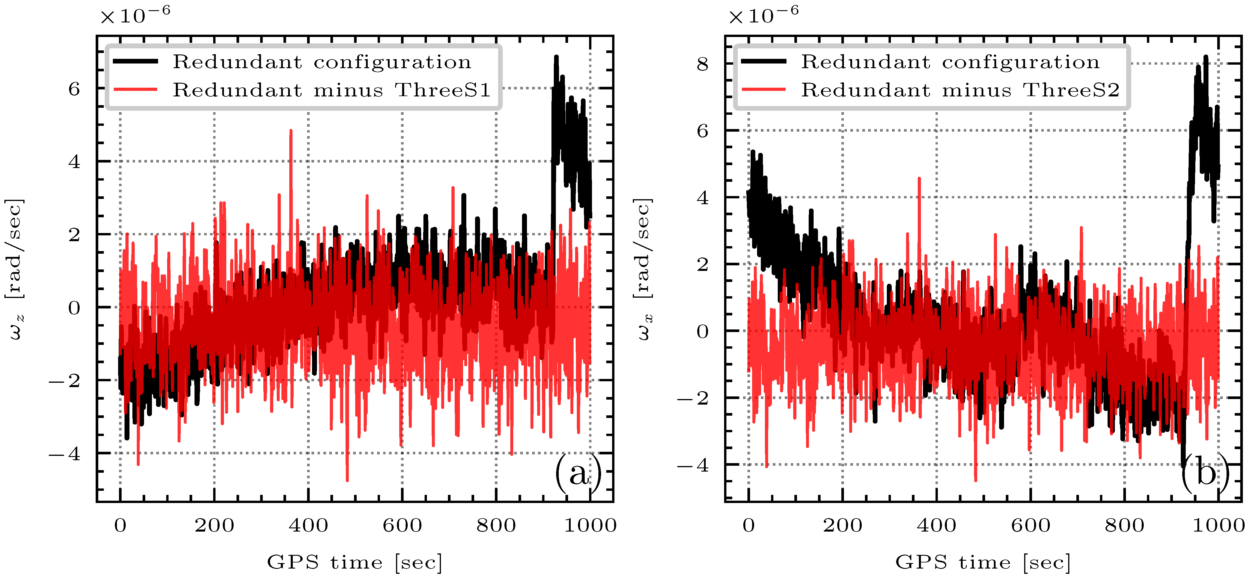
The last critical step for IMU processing is the coordinate frame transformation, in which the utilization of redundant IMU configuration is the core, see Section 3.1. Mathematically, three sensors (measurements) are sufficient for solving a linear equation that has only three unknowns (angular velocities ω x , ω y , ω z ). But due to the redundant configuration, utilization of three or four sensors is optional. In principle, there are C 4 3 options of three-sensors solution in total, but we select only two of them (denoted as ThreeS1 and ThreeS2) to make a comparative study with the four-sensors redundant configuration, see Figure 3. Comparing the red and black curves in Figure 3a, we find the differences between ’Redundant’ and ’ThreeS1’ even reach up to an equivalent level ( 10 6 ) of the signal itself, in terms of ω z (while the differences in other two components ω x and ω y are too small to be distinguished). The same phenomenon can be found also in Figure 3b, where ’Redundant’ and ’ThreeS2’ are compared in terms of ω x . Such an intolerable difference (error) indicates that a four-sensors solution must be implemented for deriving a precise angular rate. In addition, compared to the three-sensors design, the redundant design can return an estimation of the IMU error through the least square equation (residuals), which can be sent into the Kalman filter as the a-priori information. However, it is worth mentioning, the gyro provides only three angles for unknown reasons (one sensor fails) since March 2019, so that the three-sensors solution has to be applied without any better choice.

4.2. SC Processing

Original attitude measurements extracted from the SCA1A product are subject to further operations before being involved in the Kalman filter, such as time-tag correction, discarding of invalid data, sign flip, interpolation, and combination, etc., see Section 3.2. This section mainly discusses interpolation and combination.
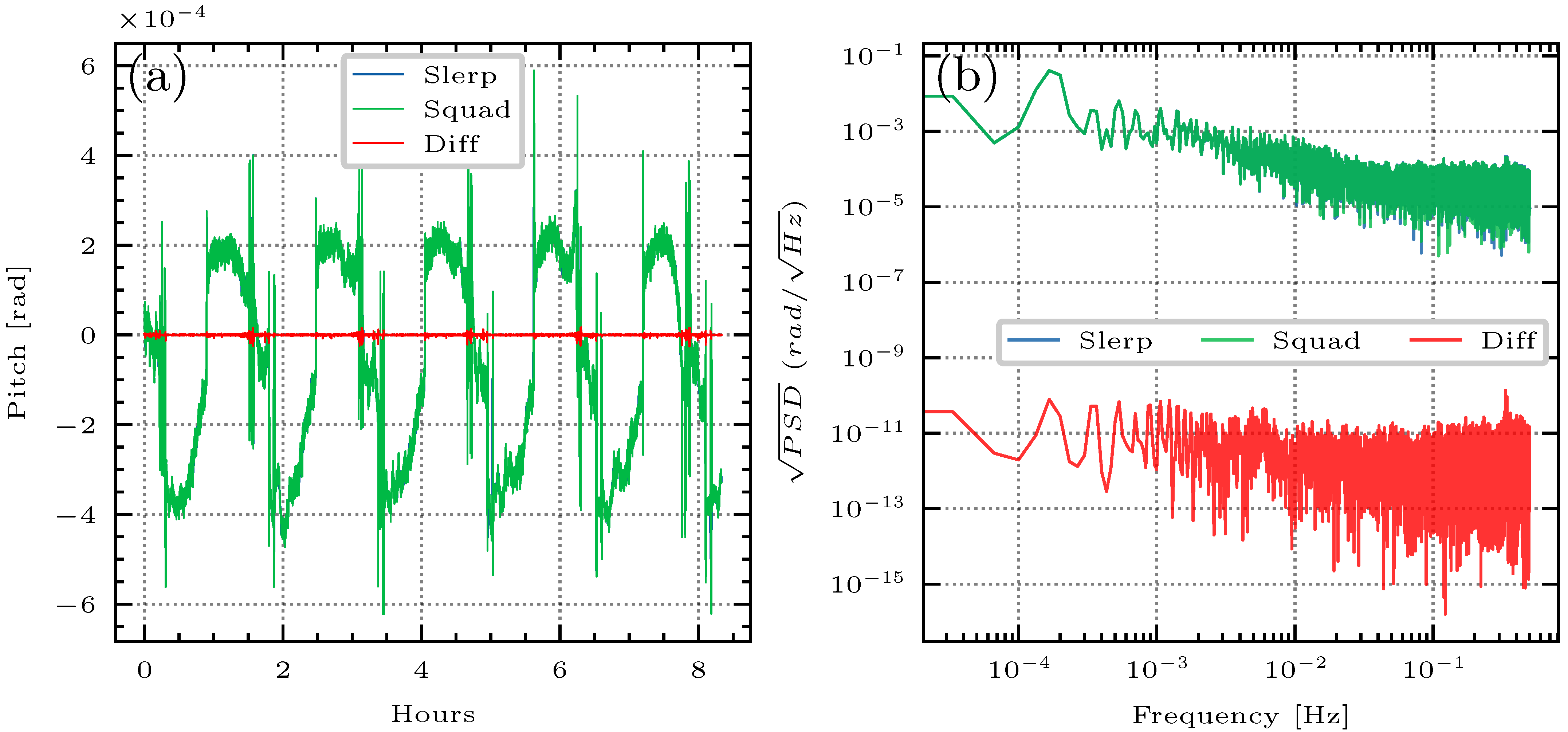
Attitude interpolation is necessary to keep time synchronization between three SCs, otherwise, the SC-combination and Kalman filter is difficult to be implemented. There are various interpolation methods as described in Section 3.2, such as Slerp and Squad. Figure 4 makes a comparative study on these two methods based on the data from 2 January 2019, aiming at analyzing the impact of the interpolation method on the attitude determination. From the time-series shown in Figure 4a, some ‘jitters’ (manifesting as a sudden jump in the attitude) are visible for both methods, and we suspect that the thruster events might be responsible for these jitters. The difference between the two methods (in red curves) turns big also at the locations where jitters take place. This is reasonable because Squad is an interpolation of higher order, which results in a smoother interpolated curve than Slerp. On the contrary, the interpolation could be used as a fast way to identify the ‘jitters’, so that in Kalman filter the SC measurements at the location of jitters could be assigned with a smaller weight to prevent the attitude jump. Back to Figure 4a, the amplitude of the difference except for the jitters is rather small compared to the signal (green curve or blue curve), implying that the attitude is not sensitive to the interpolation methods. As a correspondence, the spectral behaviors of the differences also support the conclusion, see Figure 4b, where the red curve stays much lower than the green (or blue) in all spectra.
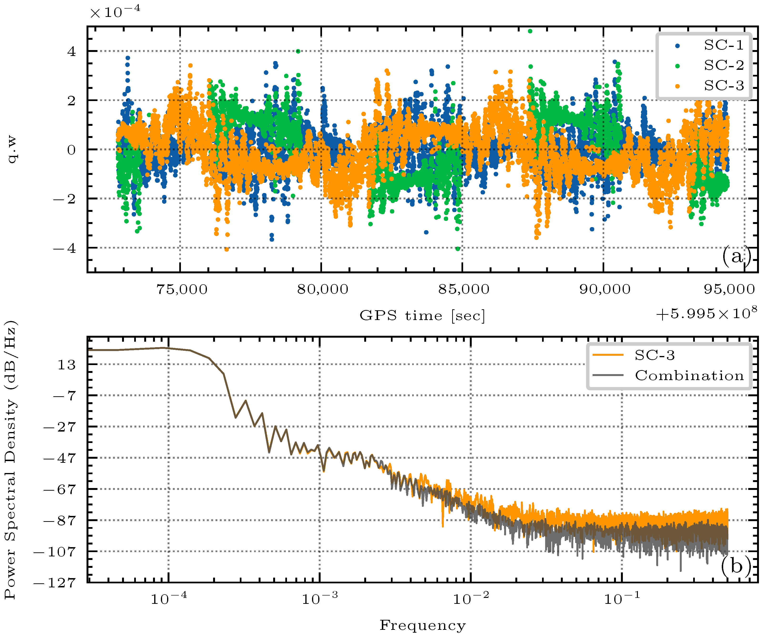
SC combination is a critical step according to the official document. In our study, the SC combination is also used for the purpose of removing outliers. In this sense, we implement the combination following the official method (see Section 3.2) on 6 December 2018 as a verification. Figure 5a plots the misalignment between three SCs, by showing the residuals computed through a ’subtraction’ of the combined result from each SC measurement. The ’subtraction’ indeed denotes a ’division’ in terms of quaternion algebra. One can at least have two findings from the Figure 5a that, (1) three SCs have an equivalent noise level with the amplitude up to 4 × 10 4 ( q . w , dimensionless), (2) the residuals of three SCs are oscillating about the zero line, implying that the combination does make an effect analogous to an ’average’. It is known that averaging is also a kind of low-pass filter that damps the high-frequency component. Accordingly, in Figure 5b, the PSD of combination result (in grey color) demonstrates a reduced high-frequency noise with respect to a single SC (e.g., SC-3, in orange color), but meanwhile the useful low-frequency signals are well retained as we expect. It is also worth mentioning that, only SCs with a quality flag (denoting a confidence level) less than 6 participate in the combination, otherwise the data of bad quality will deteriorate the combination and one can never expect a gain from such a combination. In addition, some hidden outliers in SCs can be further identified through the combination, i.e., those points of big deviations (3 times the variance) with the combination result are removed.

4.3. Kalman Filter

With the SC processing introduced in the previous section, a SC-only attitude product can be obtained. Meanwhile, fusing the SC-only data and additional IMU data through the Kalman filter can create another set of attitude products. Here, two sets of products are compared to demonstrate the advantage of the Kalman filter.
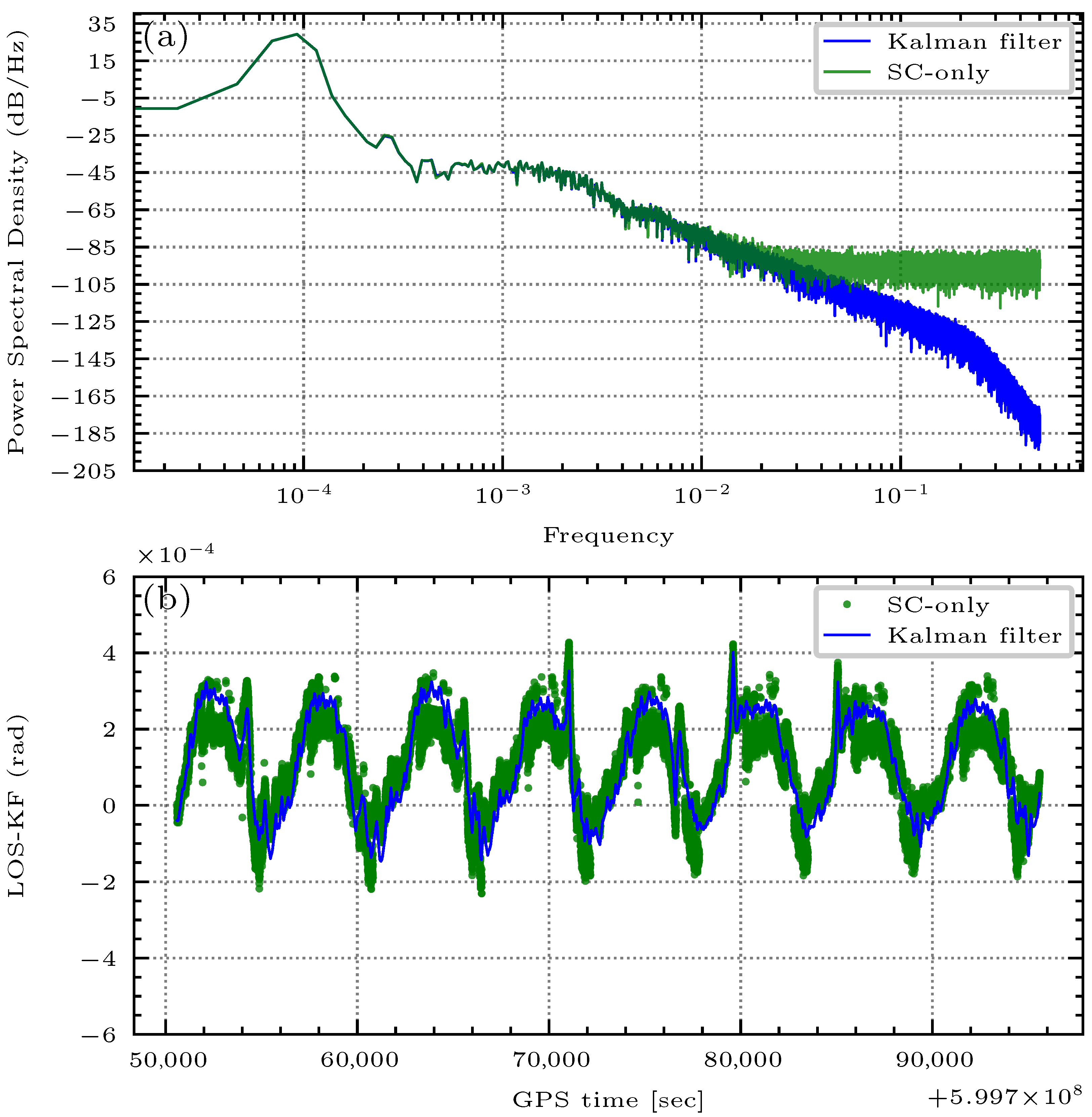
Figure 6a plots the PSDs of quaternion component q . z obtained from the Kalman filter and SC-only strategy, respectively. It can be seen that, the high-frequency noise of the Kalman filter result (in the blue curve) has been dramatically reduced with respect to the SC-only result. In fact, this phenomenon is not limited to q . z , the other components [ q . w , q . x , q . y ] have similar performances as well (not shown). In our analysis, this noise reduction should be credited to the introduction of smooth angular velocities from IMU. In this respect, IMU and SC complement each other in the Kalman filter and achieve an optimal attitude reconstruction successfully. It can be further supported by the time-series analysis in Figure 6b, where the pitch angle of the rotation matrix ( R K F L O S that represents the K-band pointing variation) is demonstrated. Obviously, the curve (in blue) of the Kalman filter is much smoother than the SC-only curve (in green), whereas their tendency is very consistent, showing good preservation of low-frequency signal and a reduction of a high-frequency noise.
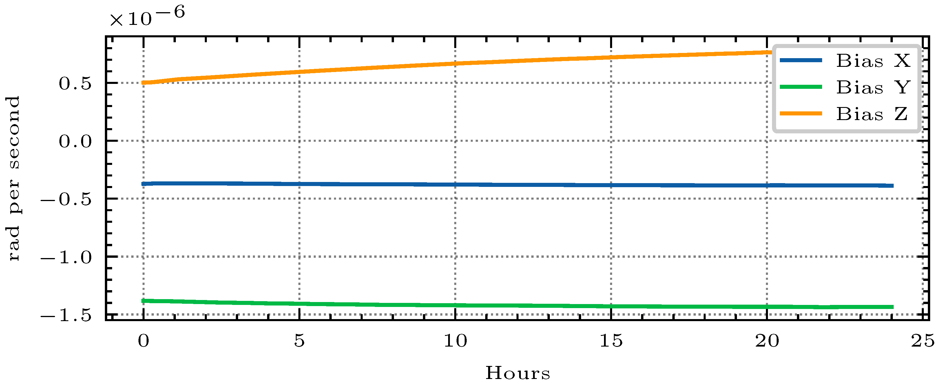
The state vectors applied in the Kalman filter as shown by Equation (11) includes also IMU bias b ( t ) other than the attitude quaternion q ( t ) . Accurate estimation of b ( t ) is important because b ( t ) and q ( t ) are dependent. Besides, the IMU bias is also an indicator of the IMU error behaviors that can be used as a-priori information within the Kalman filter to accelerate convergence. In this sense, we derive the IMU biases of 3 axes on 1 January 2019 (Sat-D) for a demonstration, see Figure 7. It can be found that the bias of Sat-D is drifting slowly with the rate recorded in Table 2. As a return, such a linear behavior exactly supports our strategy that is used to model the IMU sensors in Kalman filter, see Equation (13). Comparing Sat-C and Sat-D in Table 2, we find that Sat-C is more stable than Sat-D, implying a possible better working status of the payload in Sat-C.
Table 2 is practically useful since the absolute bias at any epoch can be derived from the starting point and the drift rate given in Table 2. In this way, the initial value of b ( t ) as the entry of Kalman filter can be appropriately determined, otherwise the filter has to go through a long-time ’learning’ process to adjust the IMU measurements, and the attitude derived during this process is apparently of bad quality. In Section 4.1, the differential method’s impact is analyzed on the level of IMU angular rate, but whether it can affect the final attitude determination remains a question. Now we can answer that, the impact is minor since the IMU bias b ( t ) estimated from Kalman filter has entirely absorbed such a systematical error, so that either differential method will result in the same attitude output (results not shown).
In addition, SC provides measurement in 2 Hz, whereas the final attitude product by design should be sampled in 1 Hz to be consistent with the official one. This implies at least two options of fusion strategy, one is [2 Hz SC + 8 Hz IMU], and another one is [1 Hz SC + 8 Hz IMU]. Through our test, the derived attitudes from these two options have only minor differences that are negligible (not shown), so that we propose the option [1 Hz SC + 8 Hz IMU] for enhancing computation efficiency, and this option is also applied for generating our attitude product HUGG-01.

5. Assessments

5.1. Inter-Satellite Pointing Analysis

HUGG-01 is produced following the methods shown in previous sections, covering the period from June 2018 to December 2020 [50]. In what follows, assessments are carried out to verify its quality. It is known that the inter-satellite pointing variations reflect the performance and characteristics of the onboard attitude and orbit control system (AOCS) since it is the task of the AOCS to keep the twin satellites in the desired orientation [31]. In other words, the inter-satellite pointing variations can somewhat represent the precision of spacecraft’s orientation. Therefore, the attitudes from the official product JPL-V04 (abbreviated with JPL) and our HUGG-01 product are firstly transformed into the inter-satellite pointing variations. Subsequently, evaluations of the pointing variation are made for JPL and HUGG-01 in terms of time-series (or PSD) of PRY (Pitch, Roll, and Yaw). Computation of the inter-satellite pointing variation as well as its PRY refers to Section 3.4.
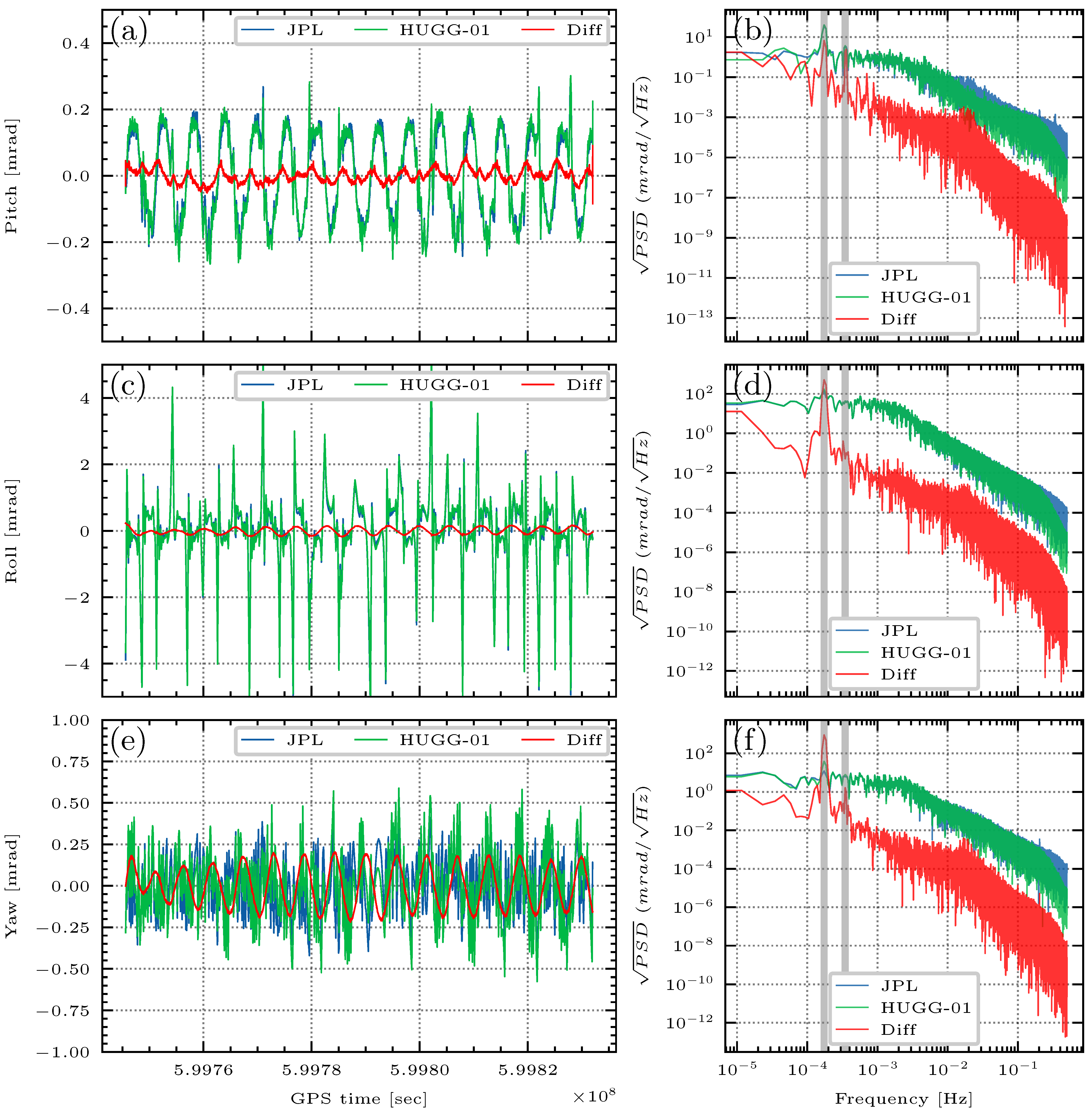
An arbitrary day’s results are demonstrated in Figure 8. From the left panel, it can be observed from the time-series (no matter for JPL or HUGG-01) that, the magnitude (maximum) of the pointing variation angles are found to be well controlled within 0.3 m r a d ( 0 . 017 ), 5 m r a d ( 0 . 286 ), and 0.6 m r a d ( 0 . 0344 ) for pitch, roll, and yaw. Since the angles denote the deviation between the KBR antenna phase center and the LOS (see Section 3.4), the small magnitude, as shown above, means good stability of AOCS in GRACE-FO within the day, as well as the rightness of our attitude computation. If we focus on the differences between HUGG-01 and JPL, it can be found that the red curves (pitch and roll) in Figure 8a,c are much smaller than the signal itself, i.e., the green curves (JPL) or the blue curves (HUGG-01). Based on the performances of pitch and roll, we may therefore conclude that HUGG-01 and JPL are fairly comparable, however, one may argue that Figure 8e reveals an opposite result. It is suspicious that the yaw angles for JPL and HUGG-01 have such a big deviation in Figure 8e. Nevertheless, the deviations (denoted as the red curves) seem to be varying in a certain ’mode’, since the curves look quite smooth. To explore the reason, the corresponding PSDs are plotted in the right panel of Figure 8 to reveal the details hidden behind the time series. Now it is quite clear from the PSD plots that, three angles indeed have quite consistent performance (unlike the time-series in the left panel) in the spectrum, manifesting as much smaller differences than the signals (red curves stay much lower than the green or blue ones). However, an obvious exception is still visible in Figure 8 PSDs. It takes place at a frequency that corresponds to approximately 1.6 h (denoted with the grey vertical line, the first one from left to right), where the red curves have an abrupt jump that leads to an undesirable peak. The peak is general for the plots of pitch, roll, and yaw, but it is especially high for yaw angle in Figure 8f, which can perfectly explain the phenomenon (fluctuation in a fixed mode) found in time-series in Figure 8e. As of now, we may conclude that, HUGG-01 is mostly comparable to JPL except for a few specific low-frequency cycling signals (corresponding to 1.6 h and suspiciously 0.8 h).
Furthermore, the cause of an abnormal signal at 1.6 h is analyzed. According to the mission design of GRACE-FO, the satellites orbit the Earth in a revolution that corresponds to also approximately 1.6 h, which is known as one-CPR (Cycle per Orbital Revolution). According to the Hill-equations (see [13,51]), many errors (known or unknown) will be excited and cause resonance in the frequency of one-CPR, including the errors un-modeled in our attitude measurements. Since the official document of JPL by Wen et al. [39] has no details about its Kalman filter configuration, we suspect that the one-CPR (and even two-CPR 0.8 h) effect has been considered as a model to be removed from the attitude measurements, with the method proposed by Harvey [33], Harvey and Sakumura [36]. Instead, the one-CPR effect has been not considered in our solution yet, and it should be the reason that HUGG-01 differs with JPL at these specific frequencies. Nevertheless, we do not think the one-CPR modeling in attitude reconstruction is necessary, if solely from the perspective of gravity recovery. To our best knowledge, in the general implementation of gravity recovery [13,42,52], the one-CPR and even tow-CPR effect will be ultimately modeled in the stage of K-band ranging data processing, which means that removal of these effects before range-rate processing is not necessary [30]. This can be also verified by our experiment on K-band ranging rate later on. In this sense, we suggest that, HUGG-01 and JPL are equivalent. In addition, from the right panel of Figure 8, we can further see that the signal content at high frequency (generally denoting the noise level) of HUGG-01 is slightly lower than that of JPL, for no matter pitch, roll, or yaw angles, despite that the green and blue curves are visually overlapping each other mostly. This may suggest that HUGG-01 achieves a slightly better performance than JPL with a lower noise level.
In order to investigate the long-term performance of HUGG-01, we additionally calculate the daily mean of the difference between HUGG-01 and JPL on the whole of January 2019, see Figure 9. It can be seen from Figure 9a,b that, there is obviously an offset (or a constant bias) between JPL and HUGG-01 for both Sat-C and Sat-D in terms of PRY angles, manifesting as a series of near-horizontal curves without apparent fluctuation. In case of Sat-C, the mean of the daily mean for roll, pitch and yaw are about [0, 5.9 × 10 4 , 0] rad. In case of Sat-D, the mean of the daily mean is about [ 0.48 × 10 4 , 3.5 × 10 4 , 0.5 × 10 4 ] rad. It is a pity that the reason why this constant offset exists remains unclear for the authors so far, which might be subject to further study in the future. Nevertheless, just like the one-CPR effect, the constant offset found here will have no influence on the gravity recovery, neither. This is because the range-rate processing removes not only the term of one-CPR, but also the constant bias, see [13,52]. Despite the bias, we can still conclude Figure 9 that, the long-term performance of HUGG-01 is fairly stable, with respect to the JPL.

5.2. K-Band Range-Rate Residual Analysis

K-band range-rate (KBRR) residuals contain useful temporal gravity information, payload error, and mis-modeling error. In this study, two sets of KBRR residual are derived from HUGG-01 and JPL attitude products, respectively. The computation method refers to Section 3.4. During the calculations, only the attitude product is changed, therefore, the differences between two sets of KBRR residuals solely reflect the deviations between attitude products. In this way, HUGG-01, and JPL are assessed.
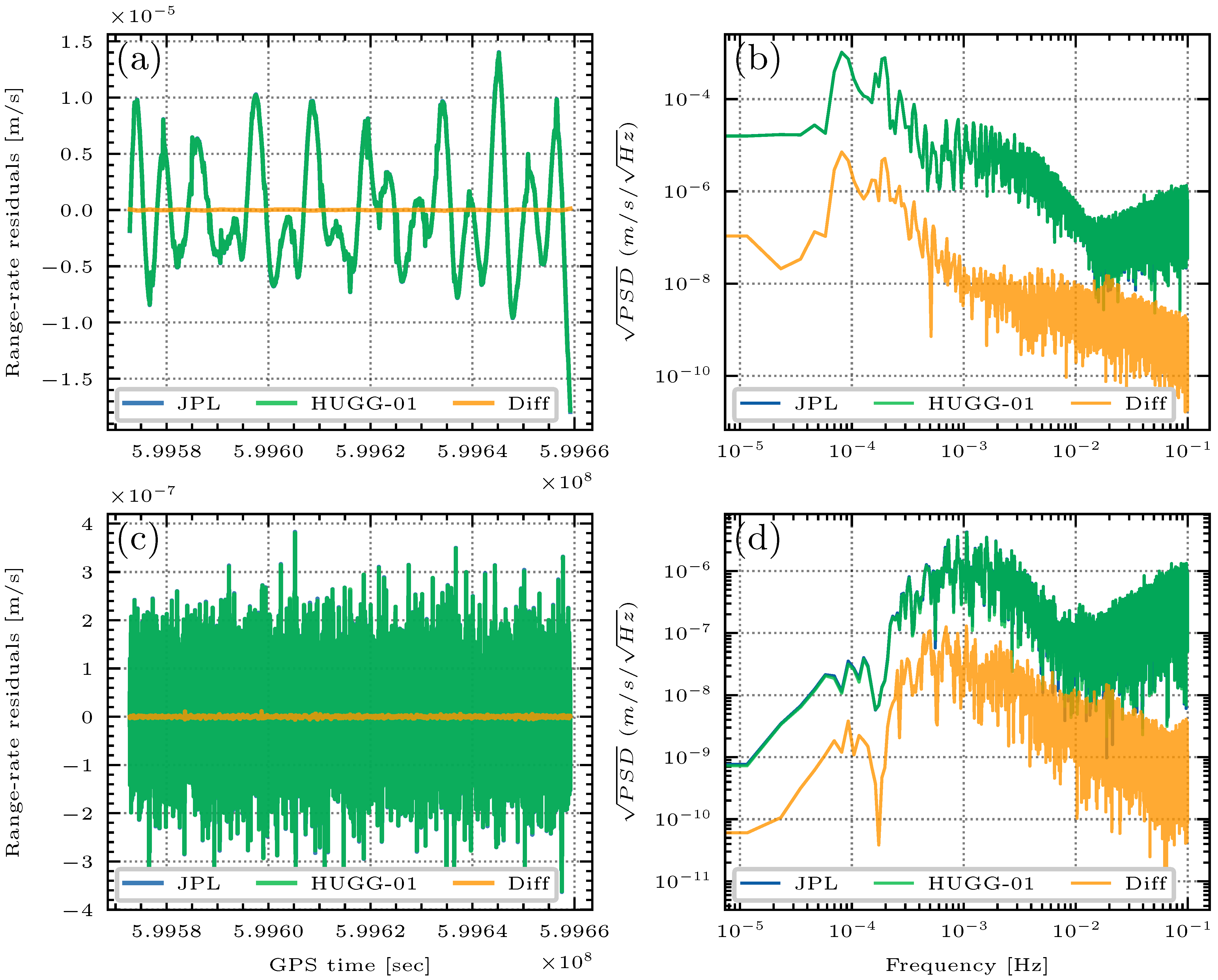
An experiment on 1 January 2019 is conducted, see Figure 10. Figure 10 demonstrates the time-series of KBRR residuals, where HUGG-01 almost overlaps JPL curves, implying that no clear differences can be found between these two products. The differences of HUGG-01 and JPL are also present, see the yellow line in Figure 10a, of which the statistics are calculated to be [mean 3.085 × 10 10 , RMS 3.234 × 10 8 ] m/s. It is known that the KBRR’s precision is at the level of 1 × 10 7 m/s, so that the differences are caused by the deviation between attitude products (HUGG-01, JPL) are apparently below the sensitivity of the K-band system. In other words, we assert that, the replacement of JPL with HUGG-01 has no influence on the KBRR residuals. The corresponding spectral performances in Figure 10b also reveal the same phenomenon, where all the spectra of differences (in yellow) stays far below the spectrum of the signal itself (in yellow or blue). As a further verification, we look into the KBRR postfit residuals as well, see Figure 10c,d. It can be seen that, after extracting the gravity signals, the low-frequency spectra of KBRR residuals have been well reduced when compared to Figure 10b. However, even in this case, the differences between JPL and HUGG-01 can not be distinguished. Based on those facts, we may conclude that, HUGG-01 and JPL achieve comparable performance in both the time domain and frequency domain. In addition, if relating the conclusion with Figure 8, it is apparent that the prominent one-CPR and constant offset previously found in the attitude differences are now invisible in the KBRR residuals, confirming again that one-CPR and constant offset in the attitude determination are not that crucial.
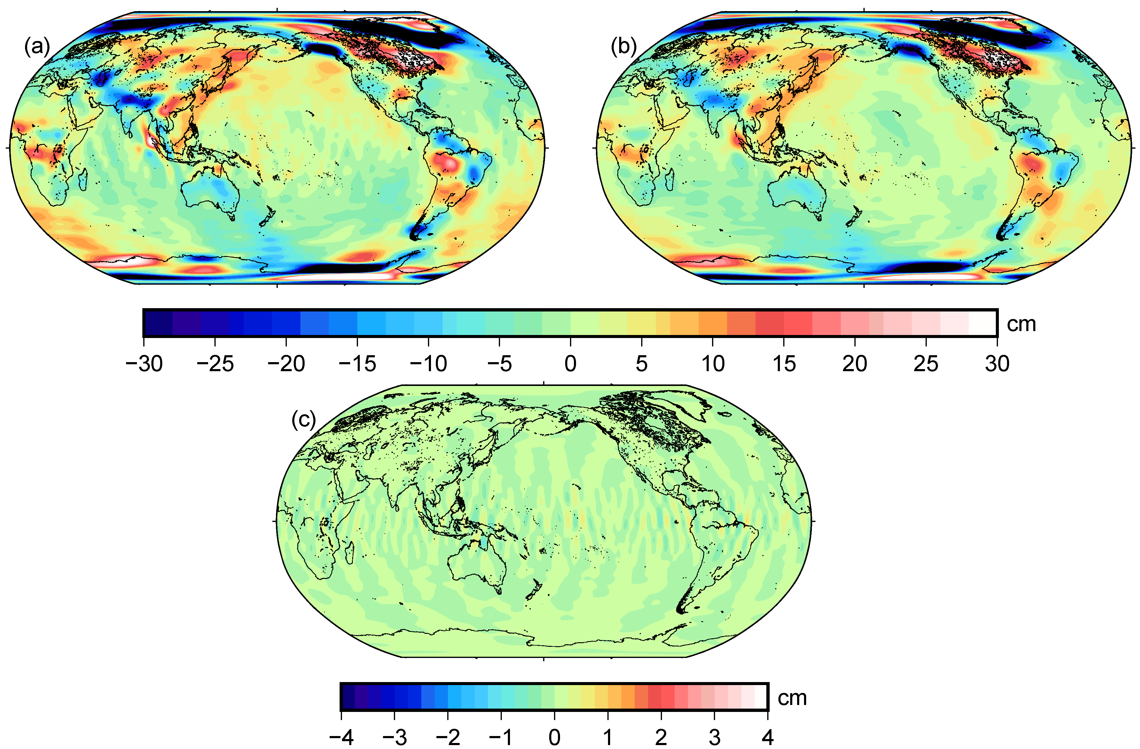
As Figure 10 only demonstrates one day’s result, we hereby calculate the monthly gravity field to directly reflect the long-term differences between two attitude products. Associated with other necessary Level-1B data (see Section 2), the gravity field on January 2019 is recovered using JPL and HUGG-01, respectively. Subsequently, post-processing of the gravity field is conducted, including removing the static part, applying simple Gaussian filtering with a radius of 300 km, applying a de-striping filter [53]. At last, the gravity field is synthesized back as a gridded EWH (Equivalent Water Height) map, as it is in Figure 11.
Figure 11a manifests the result of HUGG-01, whereas Figure 11b maps the result from the official gravity product (CSR-RL06) as the benchmark. Comparing Figure 11a and Figure 11b, we find that the spatial distribution and the variation of the signals are almost the same for our result and CSR-RL06. The places whose signal is prominent, such as the Amazon basin, Central Africa, Tibet Plateau, Antarctica, and the Arctic, can be well captured for both solutions. The good consistency confirms that our procedures of gravity inversion are reliable. Furthermore, we calculate the gravity field with JPL’s attitude product (not shown), and demonstrates its differences from the HUGG-01 gravity field in Figure 11c. Now it is quite apparent that, the differences are rather small with respect to the signals (Figure 11a), within the range of [0.78, −0.89] cm. Based on the authors’ experience, such a small difference (amplitude equivalent to ∼0.5 cm geoid height) is un-detectable for the current gravity mission. Again, such a result proves the equivalence of JPL and HUGG-01.

6. Conclusions

In this study, the data processing techniques from Level-1A to Level-1B for the attitude reconstruction of GRACE-FO are discussed, with almost all aspects/details covered. The discussion is divided into three packages: IMU processing, SC processing, and Kalman filter. For the IMU processing, we mainly analyze the influences of time-tag correction, numerical differential, and redundant sensor design. Among these, the redundant sensor design is found to have a non-negligible impact, and particular care should be given once the redundant design is unavailable (like GRACE-FO since March 2019). Nevertheless, the influences of time-tag correction and numerical differential can be ignored. For the SC processing, we mainly analyze the influences of quaternion interpolation and combination methods. It is found that the interpolation method’s impact is below the noise level of current attitude measurements. On the contrary, the combination significantly reduces the high-frequency noise of each SC. For the Kalman filter, we mainly contrast the SC-only solution with the fusion result, which well demonstrates the added value of the IMU on reducing the high-frequency noise. In addition, the a-priori information of the angular rate bias is derived and recorded, so that the Kalman filter can be well initialized and tuned. We think the demonstrated details or results from the above discussions might provide useful information or accumulate experience for the next generation’s attitude product.
In this way, we successfully calculate an alternative GRACE-FO Level-1B attitude solution, namely HUGG-01 covering from June 2018 to December 2020 [50], which achieves a comparable precision as the latest official attitude Level-1B product (JPL-V04). Analysis of the inter-satellite pointing variation demonstrates that the error of HUGG-01 are well controlled within 0.3 m r a d ( 0 . 017 ), 5 m r a d ( 0 . 286 ), and 0.6 m r a d ( 0 . 0344 ), which satisfies the mission design. Further comparisons between HUGG-01 and JPL-V04 reveal a difference of 3.234 × 10 8 m/s in terms of range-rate residuals, and ∼0.5 cm in terms of geoid height, which could be nevertheless ignored [2]. Through a spectral analysis, HUGG-01 is found to contain even less high-frequency noise than JPL-V04, but the advantage of this characteristic still requires to be further investigated. Based on the demonstrated results, one can have no worry to use HUGG-01 as an alternative choice in the gravity recovery as well as the related researches.
Despite the good agreement between HUGG-01 and JPL-V04, there are still some deviations that are worthy of further studies, such as the obvious one(two)-CPR effect and a constant offset found in Figure 8 and Figure 9. Although the one(two)-CPR effect and the constant offset have no impact on the gravity recovery, they still indicate that some deficiencies might still exist in our solution or possibly JPL’s solution, which is unclear yet. In particular, the constant offset may hint at a misalignment of the SC configuration. To our best knowledge, SC configuration is provided by the QSA1B file for GRACE-FO, whereas the QSA1B only offers the alignment data on the ground. Once there is a calibration on the orbit, a constant offset in the attitude will be caused. In this sense, a converse study from the offset in the attitude to the on-orbit calibration might be interesting, which will be subject to our next study. As well, a thorough investigation into the noise of every single SC should be done in the future to conquer the CPR effect. Besides, there are also some possible extensions of this study, such as the determination of a new set of antenna offset corrections with HUGG-01, which is crucial for gravity recovery. In addition, the LRI steering mirror data of GRACE-FO has proved to be valuable for enhancing spacecraft’s attitude precision as well, but how to appropriately fuse this data with SC and IMU is still challenging and is subject to a further study.

Author Contributions

Conceptualization, F.Y. and L.L.; methodology, F.Y. and L.L; software, F.Y. and L.L.; validation, C.W.; formal analysis, Z.L.; investigation, L.L.; resources, L.L.; data curation, L.L.; writing—original draft preparation, F.Y.; writing—review and editing, L.L., C.W. and Z.L.; visualization, F.Y. and L.L.; supervision, Z.L.; project administration, Z.L.; funding acquisition, F.Y., L.L. and Z.L. All authors have read and agreed to the published version of the manuscript.

Funding

This research is funded by the National Natural Science Foundation of China (Grant No.41804016, No.41931074, No.42061134007, No.42174103, No.41704013, No.42061134010) and State Key Laboratory of Geo-Information Engineering (No. SKLGIE 2019-M-1-2).

Institutional Review Board Statement

Not applicable.

Informed Consent Statement

Not applicable.

Data Availability Statement

The authors state that all the data in this study are publicly available. The input data including GRACE-FO Level-1A, Level-1B and Level-2 data are obtained from GFZ data center (ftp://isdcftp.gfz-potsdam.de/grace-fo/, accessed on 9 November 2021). The output, our new attitude product HUGG-01, can be also downloaded from the figshare site since December 2021 (https://doi.org/10.6084/m9.figshare.17009831, accessed on 9 November 2021).

Acknowledgments

The authors would like to thank the editor and the reviewers for their helpful comments. Thanks also give to Max-Planck-Society and the Chinese Academy of Sciences within the LEGACY (“Low-Frequency Gravitational Wave Astronomy in Space”) collaboration (M.IF.A.QOP18098).

Conflicts of Interest

The authors declare no conflict of interest.

References

  1. Tapley, B.D.; Bettadpur, S.; Watkins, M.; Reigber, C. The gravity recovery and climate experiment: Mission overview and early results. Geophys. Res. Lett. 2004, 31. [Google Scholar] [CrossRef] [Green Version]
  2. Kornfeld, R.P.; Arnold, B.W.; Gross, M.A.; Dahya, N.T.; Klipstein, W.M.; Gath, P.F.; Bettadpur, S. GRACE-FO: The Gravity Recovery and Climate Experiment Follow-On Mission. J. Spacecr. Rocket. 2019, 56, 931–951. [Google Scholar] [CrossRef]
  3. Kusche, J.; Klemann, V.; Bosch, W. Mass distribution and mass transport in the Earth system. J. Geodyn. 2012, 59, 1–8. [Google Scholar] [CrossRef] [Green Version]
  4. Tapley, B.; Watkins, M.; Flechtner, F.; Reigber, C.; Bettadpur, S.; Rodell, M.; Sasgen, I.; Famiglietti, J.S.; Landerer, F.W.; Chambers, D.P.; et al. Contributions of GRACE to understanding climate change. Nat. Clim. Chang. 2019, 9, 358–369. [Google Scholar] [CrossRef]
  5. Dahle, C.; Murböck, M.; Flechtner, F.; Dobslaw, H.; Michalak, G.; Neumayer, K.; Abrykosov, O.; Reinhold, A.; König, R.; Sulzbach, R.; et al. The GFZ GRACE RL06 Monthly Gravity Field Time Series: Processing Details and Quality Assessment. Remote Sens. 2019, 11, 2116. [Google Scholar] [CrossRef] [Green Version]
  6. Ramillien, G.; Biancale, R.; Gratton, S.; Vasseur, X.; Bourgogne, S. GRACE-derived surface water mass anomalies by energy integral approach: Application to continental hydrology. J. Geod. 2011, 85, 313–328. [Google Scholar] [CrossRef]
  7. Famiglietti, J.S.; Rodell, M. Water in the balance. Science 2013, 340, 1300–1301. [Google Scholar] [CrossRef] [PubMed]
  8. Rodell, M.; Famiglietti, J.S.; Wiese, D.N.; Reager, J.T.; Beaudoing, H.K.; Landerer, F.W.; Lo, M.H. Emerging trends in global freshwater availability. Nature 2018, 557, 651–659. [Google Scholar] [CrossRef]
  9. Sasgen, I.; Konrad, H.; Ivins, E.; Van den Broeke, M.; Bamber, J.; Martinec, Z.; Klemann, V. Antarctic ice-mass balance 2003 to 2012: Regional reanalysis of GRACE satellite gravimetry measurements with improved estimate of glacial-isostatic adjustment based on GPS uplift rates. Cryosphere 2013, 7, 1499–1512. [Google Scholar] [CrossRef] [Green Version]
  10. Velicogna, I.; Mohajerani, Y.; Landerer, F.; Mouginot, J.; Noel, B.; Rignot, E.; Sutterley, T.; van den Broeke, M.; van Wessem, M.; Wiese, D. Continuity of Ice Sheet Mass Loss in Greenland and Antarctica From the GRACE and GRACE Follow-On Missions. Geophys. Res. Lett. 2020, 47, e2020GL087291. [Google Scholar] [CrossRef] [Green Version]
  11. Panet, I.; Sylvain, B.; Narteau, C.; Rémy, D.; Lemoine, J.M. Migrating pattern of deformation prior to the Tohoku-Oki earthquake revealed by GRACE data. Nat. Geosci. 2018, 11, 367–373. [Google Scholar] [CrossRef]
  12. Cambiotti, G.; Douch, K.; Cesare, S.; Haagmans, R.; Sneeuw, N.; Anselmi, A.; Anna Maria, M.; Sabadini, R. On Earthquake Detectability by the Next-Generation Gravity Mission. Surv. Geophys. 2020, 41, 1049–1074. [Google Scholar] [CrossRef]
  13. Kim, J. Simulation Study of a Low-Low Satellite-to-Satellite Tracking Mission. Ph.D. Thesis, The University of Texas at Austin, Austin, TX, USA, 2000. [Google Scholar]
  14. Goswami, S.; Francis, S.P.; Bandikova, T.; Spero, R.E. Analysis of GRACE Follow-On Laser Ranging Interferometer derived inter-satellite pointing angles. IEEE Sens. J. 2021, 21, 19209–19221. [Google Scholar] [CrossRef]
  15. Flechtner, F.; Neumayer, K.H.; Dahle, C.; Dobslaw, H.; Fagiolini, E.; Raimondo, J.C.; Güntner, A. What Can be Expected from the GRACE-FO Laser Ranging Interferometer for Earth Science Applications? Surv. Geophys. 2016, 37, 453–470. [Google Scholar] [CrossRef] [Green Version]
  16. Dobslaw, H.; Bergmann-Wolf, I.; Dill, R.; Poropat, L.; Thomas, M.; Dahle, C.; Esselborn, S.; König, R.; Flechtner, F. A new high-resolution model of non-tidal atmosphere and ocean mass variability for de-aliasing of satellite gravity observations: AOD1B RL06. Geophys. J. Int. 2017, 211, 263–269. [Google Scholar] [CrossRef] [Green Version]
  17. Behzadpour, S.; Mayer-Gürr, T.; Flury, J.; Klinger, B.; Goswami, S. Multiresolution wavelet analysis applied to GRACE range-rate residuals. Geosci. Instrum. Methods Data Syst. 2019, 8, 197–207. [Google Scholar] [CrossRef] [Green Version]
  18. Yang, F.; Forootan, E.; Wang, C.; Kusche, J.; Luo, Z. A New 1-Hourly ERA5-Based Atmosphere De-Aliasing Product for GRACE, GRACE-FO, and Future Gravity Missions. J. Geophys. Res. Solid Earth 2021, 126, e2021JB021926. [Google Scholar] [CrossRef]
  19. Frommknecht, B. Integrated Sensor Analysis of the GRACE Mission. Ph.D. Thesis, Leibniz University Hannover, Hanover, Germany, 2007. [Google Scholar]
  20. Bandikova, T.; Flury, J. Improvement of the GRACE star camera data based on the revision of the combination method. Adv. Space Res. 2014, 54, 1818–1827. [Google Scholar] [CrossRef]
  21. Gruber, T.; Team, N.D. e2. Motion: Earth System Mass Transport Mission (Square)—Concept for a Next Generation Gravity Field Mission—Final Report of Project Satellite Gravimetry of the Next Generation (NGGM-D). Deutsche Geodätische Kommission der Bayerischen Akademie der Wissenschaften, Reihe B Angewandte Geodäsie Heft Nr. 318, München; Technical Report; Deutsche Geodätische Kommission der Bayerischen Akademie der Wissenschaften: Munich, Germany, 2014; ISBN 978-3-7696-8597-8. [Google Scholar]
  22. Pail, R.; Chen, Q.; Engels, J.; Hauk, M.; Liu, W.; Purkhauser, A.; Saemian, P.; Sneeuw, N.; Tourian, M.; Visser, P.; et al. Additional Constellation and Scientific Analysis of the Next Generation Gravity Mission Concept (ADDCON); Technical Report; Issue 3.1, ESA Contract No. 4000118480/16/NL/FF/gp; Technical University of Munich: Munich, Germany, 2018. [Google Scholar]
  23. Zhou, H.; Luo, Z.; Zhou, Z.; Yang, F.; Yang, S. What Can We Expect from the Inclined Satellite Formation for Temporal Gravity Field Determination? Surv. Geophys. 2021, 42, 699–726. [Google Scholar] [CrossRef]
  24. Wiese, D.N.; Visser, P.; Nerem, R.S. Estimating low resolution gravity fields at short time intervals to reduce temporal aliasing errors. Adv. Space Res. 2011, 48, 1094–1107. [Google Scholar] [CrossRef]
  25. Purkhauser, A.; Pail, R. Next generation gravity missions: Near-real time gravity field retrieval strategy. Geophys. J. Int. 2019, 217, 1314–1333. [Google Scholar] [CrossRef]
  26. Abich, K.; Abramovici, A.; Amparan, B.; Baatzsch, A.; Okihiro, B.; Barr, D.; Bize, M.; Bogan, C.; Braxmaier, C.; Burke, M.; et al. In-Orbit Performance of the GRACE Follow-on Laser Ranging Interferometer. Phys. Rev. Lett. 2019, 123, 031101. [Google Scholar] [CrossRef] [Green Version]
  27. Save, H. Status of CSR RL06 GRACE reprocessing and preliminary results. In Proceedings of the Agu Fall Meeting, New Orleans, LA, USA, 1–15 December 2017. [Google Scholar]
  28. Kruizinga, G.L.; Bertiger, W.I.; Case, K.E.; Finch, C.J.; Wu, S.C. GRACE Level-1 Processing Status. In Proceedings of the AGU Fall Meeting Abstracts, San Francisco, CA, USA, 8–12 December 2003. [Google Scholar]
  29. Wu, S.C.; Kruizinga, G.; Bertiger, W. Algorithm Theoretical Basis Document for GRACE Level-1B Data Processing V1.2. GRACE Technical Report; Jet Propulsion Laboratory, California Institute of Technology: Pasadena, CA, USA, 2006. [Google Scholar]
  30. Horwath, M.; Lemoine, J.M.; Biancale, R.; Bourgogne, S. Improved GRACE Science Results After Adjustment Of Geometric Biases In The Level-1b K-Band Ranging Data. J. Geod. 2011, 85, 23–38. [Google Scholar] [CrossRef]
  31. Bandikova, T.; Flury, J.; Ko, U.D. Characteristics and accuracies of the GRACE inter-satellite pointing. Adv. Space Res. 2012, 50, 123–135. [Google Scholar] [CrossRef]
  32. Inácio, P.; Ditmar, P.; Klees, R.; Farahani, H.H. Analysis of star camera errors in GRACE data and their impact on monthly gravity field models. J. Geod. 2015, 89, 551–571. [Google Scholar] [CrossRef] [Green Version]
  33. Harvey, N. GRACE star camera noise. Adv. Space Res. 2016, 58, 408–414. [Google Scholar] [CrossRef]
  34. Chen, Q.; Shen, Y.; Chen, W.; Zhang, X.; Hsu, H. An improved GRACE monthly gravity field solution by modeling the non-conservative acceleration and attitude observation errors. J. Geod. 2016, 90, 503–523. [Google Scholar] [CrossRef]
  35. Romans, L. Optimal Combination of Quaternions from Multiple Star Cameras; JPL Internal Memorandum; NASA Jet Propulsion Laboratory: Pasadena, CA, USA, 2003.
  36. Harvey, N.; Sakumura, C. Results from a GRACE/GRACE-FO attitude reconstruction Kalman filter. J. Geod. 2019, 93, 1881–1896. [Google Scholar] [CrossRef]
  37. Klinger, B.; Mayer-Gürr, T. Combination of GRACE star camera and angular acceleration data. In Proceedings of the EGU General Assembly, Vienna, Austria, 27 April–2 May 2014. [Google Scholar]
  38. Goswami, S.; Klinger, B.; Weigelt, M.; Mayer-Gürr, T. Analysis of attitude errors in GRACE range-rate residuals—A comparison between SCA1B and the reprocessed attitude fused product (SCA1B +ACC1B). IEEE Sens. Lett. 2018, 2, 1–4. [Google Scholar] [CrossRef]
  39. Wen, H.Y.; Kruizinga, G.; Paik, M.; Landerer, F.; Bertiger, W.; Sakumura, C.; Bandikova, T.; Mccullough, C. Gravity Recovery and Climate Experiment Follow-On (GRACE-FO) Level-1 Data Product User Handbook; Technical Report, GRACE Technical Report, JPL D-56935 (URS270772); USA, 2019. Available online: https://podaac-tools.jpl.nasa.gov/drive/files/allData/gracefo/docs/GRACE-FO_L1_Handbook.pdf (accessed on 9 November 2021).
  40. Patel, C.R. Analyzing and Monitoring GRACE-FO Star Camera Performance in a Changing Environment. Master’s Thesis, The University of Texas at Austin, Austin, TX, USA, 2020. [Google Scholar]
  41. Yang, F.; Kusche, J.; Forootan, E.; Rietbroek, R. Passive-ocean radial basis function approach to improve temporal gravity recovery from GRACE observations. J. Geophys. Res. Solid Earth 2017, 122, 6875–6892. [Google Scholar] [CrossRef] [Green Version]
  42. Yang, F.; Forootan, E.; Schumacher, M.; Shum, C.; Zhong, M. Evaluating non-tidal atmospheric products by measuring GRACE K-band range rate residuals. Geophys. J. Int. 2018, 215, 1132–1147. [Google Scholar] [CrossRef]
  43. Jafari, M. Optimal redundant sensor configuration for accuracy increasing in space inertial navigation system. Aerosp. Sci. Technol. 2015, 47, 467–472. [Google Scholar] [CrossRef] [Green Version]
  44. Trawny, N.; Roumeliotis, S. Indirect Kalman Filter for 3D Attitude Estimation. A Tutorial for Quaternion Algebra; Technical Report Number 2005-002, Rev. 57; University of Minnesota: Minneapolis, MN, USA, 2005. [Google Scholar]
  45. Mandea, M.; Holschneider, M.; Lesur, V.; Luhr, H. The Earth’s magnetic field at the CHAMP satellite epoch. In System Earth via Geodetic-Geophysical Space Techniques; Springer: Berlin/Heidelberg, Germany, 2011. [Google Scholar]
  46. Siemes, C. GOCE Gradiometer Calibration and Level 1b Data Processing; Technical Report EWP-2384; European Space Agency: Paris, France, 2011. [Google Scholar]
  47. Stummer, C.; Fecher, T.; Pail, R. Alternative method for angular rate determination within the GOCE gradiometer processing. J. Geod. 2011, 85, 585–596. [Google Scholar] [CrossRef]
  48. Lefferts, E.J.; Markley, F.L.; Shuster, M. Kalman Filtering for Spacecraft Attitude Estimation. J. Guid. Control Dyn. 1982, 5, 536–542. [Google Scholar] [CrossRef]
  49. Wang, F. Study on Center of Mass Calibration and K-band Ranging System Calibration of the GRACE Mission. Ph.D. Thesis, The University of Texas at Austin, Austin, TX, USA, 2003. [Google Scholar]
  50. Liang, L.; Yang, F. An alternative SCA1B product for GRACE-FO from 2018-06 to 2020-12. Figshare 2021. [Google Scholar] [CrossRef]
  51. Liang, L.; Yu, J.; Wang, C.; Zhong, M.; Feng, W.; Wan, X.; Chen, W.; Yan, Y. Influence of the Low-Frequency Error of the Residual Orbit on Recovering Time-Variable Gravity Field from the Satellite-To-Satellite Tracking Mission. Remote Sens. 2021, 13, 1118. [Google Scholar] [CrossRef]
  52. Zhao, Q.; Guo, J.; Hu, Z.; Shi, C.; Liu, J.; Cai, H.; Liu, X. GRACE gravity field modeling with an investigation on correlation between nuisance parameters and gravity field coefficients. Adv. Space Res. 2011, 47, 1833–1850. [Google Scholar] [CrossRef]
  53. Wahr, J.; Molenaar, M.; Bryan, F. Time variability of the Earth’s gravity field: Hydrological and oceanic effects and their possible detection using GRACE. J. Geophys. Res. Solid Earth 1998, 103, 30205–30229. [Google Scholar] [CrossRef]
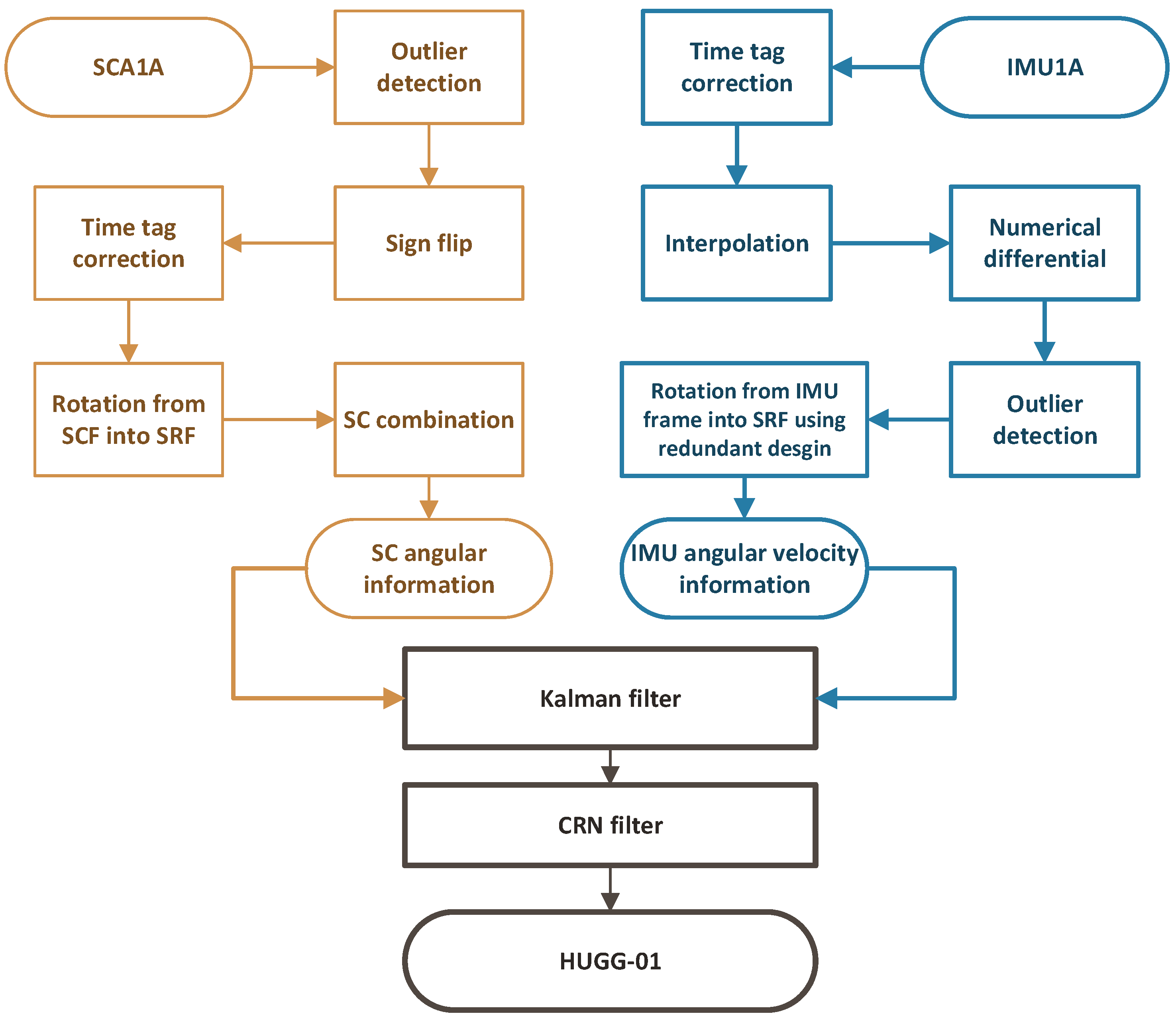
Figure 1. Diagram of our attitude reconstruction scheme. Box in dark yellow represents the SC processing, and box in cyan represents the IMU processing. The stage of data fusion is marked in black.
Remotesensing 14 00126 g001
Figure 2. An example (5 December 2018 Sat-C IMU-3) of angular rate computation. (a) is the angular rate result computed with POST method. (bd) denote the angular rate differences between three methods: MID, POST and PRE. In (bd), the mean is marked in dashed yellow line and the 1-sigma variance is marked in red dashed line to quantify the difference.
Remotesensing 14 00126 g002
Figure 3. Comparisons of derived angular velocities between four-sensors redundant configuration and three-sensors strategies. (a) denotes the ω z , and (b) denotes the ω x .
Remotesensing 14 00126 g003
Figure 4. Comparisons of the inter-satellite pointing variation (in terms of the pitch, see Section 3.4) derived from Slerp and Squad interpolation methods, respectively. Results of time-series and spectra (power spectral density) are shown in the left (a) and right (b), respectively.
Remotesensing 14 00126 g004
Figure 5. (a) Misalignment between three SCs and (b) their comparisons with the combination result on 6 December 2018 for GRACE-FO Sat-C. All are performed in terms of quaternion component q . w as an example.
Remotesensing 14 00126 g005
Figure 6. Comparisons of derived attitude between SC-only strategy and Kalman filter strategy, on 3 January 2019 for GRACE-FO Sat-D (a) plots the PSDs of quaternion component q . z obtained from the Kalman filter and SC-only strategy, respectively. In particular, (b) is carried out in the frame of ’LOS-KF’, denoting the inter-satellite pointing variation, see Section 3.4.
Remotesensing 14 00126 g006
Figure 7. IMU angular rate bias about axis X, Y and Z for GRACE-FO Sat-D on 2 January 2019 in SRF frame.
Remotesensing 14 00126 g007
Figure 8. Comparisons between JPL and HUGG-01 in terms of pointing variations on 3 January 2019 for Sat-D. The pointing variations are expressed in terms of pitch (a,b), roll (c,d) and yaw (e,f) angles with their mean subtracted. From left to right, the first grey vertical line of (b,d,f) denotes the one-CPR frequency that corresponds to 1.6 h, and the second one denotes the two-CPR frequency that corresponds to 0.8 h.
Remotesensing 14 00126 g008
Figure 9. Time series of the daily mean of (JPL minus HUGG-01) on January 2019. (a,b) denote results of GRACE-FO Sat-C and Sat-D, respectively.
Remotesensing 14 00126 g009
Figure 10. K-band range-rate residuals derived from the JPL (in blue) and HUGG-01 (in green) attitude products on 1 January 2019. Their differences are denoted with the orange curve. (a,b) denote the pre-fit residuals, whereas (c,d) denote the post-fit residuals after extracting the gravity field signals.
Remotesensing 14 00126 g010
Figure 11. Gravity fields on January 2019 recovered from HUGG-01 (a) and CSR-RL06 (b), in terms of EWH [cm]. The gravity differences between those derived from HUGG-01 and JPL attitude products are shown in (c).
Remotesensing 14 00126 g011
Table 1. Statistical result (percentage) for time-tag (GPS time) differences between ours and the official one. The unit of time difference is [second].
Difference Value a One DayOne Month
=0 × 10 6 44.38%44.12%
= 1 × 10 6 55.62%55.50%
= 2 × 10 6 0%0.38%
≥3 × 10 6 0%0%
a denotes an absolute value.
Table 2. The IMU bias and its drift rate for GRACE-FO. Unit of bias is [rad/s], and drift rate is [rad/s/day].
AxisSatBias Drift RateBias a
XC + 1.7648 × 10 14 + 1.5085 × 10 6
YC + 2.1050 × 10 14 4.2323 × 10 7
ZC + 6.5516 × 10 14 + 8.9350 × 10 7
XD 1.7788 × 10 13 3.7298 × 10 7
YD 6.0937 × 10 13 1.3832 × 10 6
ZD + 3.3403 × 10 12 + 5.0151 × 10 7
a denotes the bias at 1 January 2019, 00:00:00.
Publisher’s Note: MDPI stays neutral with regard to jurisdictional claims in published maps and institutional affiliations.