Article

Sensitivity of Near-Infrared Permanent Laser Scanning Intensity for Retrieving Soil Moisture on a Coastal Beach: Calibration Procedure Using In Situ Data

1
Department of Geoscience and Remote Sensing, Delft University of Technology, 2628 CN Delft, The Netherlands
2
Department of Hydraulic Engineering, Delft University of Technology, 2628 CN Delft, The Netherlands
*
Author to whom correspondence should be addressed.
Remote Sens. 2021, 13(9), 1645; https://doi.org/10.3390/rs13091645
Submission received: 22 March 2021 / Revised: 18 April 2021 / Accepted: 21 April 2021 / Published: 23 April 2021

Abstract

:
Anthropogenic activities and climate change in coastal areas require continuous monitoring for a better understanding of environmental evolution and for the implementation of protection strategies. Surface moisture is one of the important drivers of coastal variability because it highly affects shoreward sand transport via aeolian processes. Several methods have been explored for measuring surface moisture at different spatiotemporal resolutions, and in recent years, light detection and ranging (LiDAR) technology has been investigated as a remote sensing tool for high-spatiotemporal-resolution moisture detection. The aim of the present study is the assessment of the performance of a permanent terrestrial laser scanner (TLS) with an original setting located on a high position and hourly scanning of a wide beach area stretching from a swash zone to the base of a dune in order to evaluate the soil moisture at a high spatiotemporal resolution. The reflectance of a Riegl-VZ2000 located in Noordwijk on the Dutch coast was used to assess a new calibration curve that allows the estimation of soil moisture. Three days of surveys were conducted to collect ground-truth soil moisture measurements with a time-domain reflectometry (TDR) sensor at 4 cm depth. Each in situ measurement was matched with the closest reflectance measurement provided by the TLS; the data were interpolated using a non-linear least squares method. A calibration curve that allowed the estimation of the soil moisture in the range of 0–30% was assessed; it presented a root-mean-square error (RMSE) of 4.3% and a coefficient of determination (R-square) of 0.86. As an innovative aspect, the calibration curve was tested under different circumstances, including weather conditions and tidal levels. Moreover, the TDR data collected during an independent survey were used to validate the assessed curve. The results show that the permanent TLS is a highly suitable technique for accurately evaluating the surface moisture variations on a wide sandy beach area with a high spatiotemporal resolution.

1. Introduction

Anthropogenic activities and climate change are an increasing risk factor for coastal environments, as they cause ecological and socioeconomic damage. The influences of weather conditions, changing tides, waves, river outflow, and human construction on sandy coasts have triggered the need for continuous monitoring of coastal areas. This will lead to a better understanding of the environmental processes and will enable the evaluation of coastal protection projects.
Coastal dunes form the main line of defense against the sea on sandy coasts. Their evolution depends on sediment supply, beach morphology, vegetation, and climatic variables [1].
Characterization of aeolian sand transport is essential for modeling beach and dune sediment budgets. Aeolian transport over beaches depends on several spatially and temporally variable environmental parameters, i.e., sand supply and wind speed and direction, [2,3,4], and it is further influenced by topography, moisture content, and bedform development [5]. It is widely recognized that cohesive forces associated with the presence of moisture in surface sediment can act as an important control for rates of wind-blown sand transport [6]. Coarse shell layers can prevent sand transport on nourished beaches [7], while on natural beaches, surface moisture is a key parameter [4,8,9,10,11], as it influences aeolian sediment transport by increasing the velocity threshold required to mobilize sediment [12,13]. Several models—both empirical and physically based—have been proposed to represent this influence, and the basic mechanics have been clearly documented [13,14,15]. More specifically, a moisture content higher than 10% by mass prohibits transport [11]; therefore, monitoring soil moisture content is of utmost importance for a proper stability assessment.
The thickness of the sand surface layer that is of interest for aeolian transport is quite thin, ranging from a few millimeters to a few centimeters [16]. The upper beach, which is not influenced by the tides, generally has a low moisture content (<5%), and its low variability depends on the ground properties and atmospheric processes [6]. Moving towards the sea, the moisture variability increases (5–25%) due to the variation in the depth of the water level beneath the sand bed as a consequence of the tides [6,17,18]. Above the low-tide level, the sand remains saturated, and the fringe above the water level intersects with the surface [6,19].
In recent decades, these effects have mostly been studied at the scales of individual storm events and tidal cycles and at a low spatial and temporal resolution. Studying surface moisture has been difficult due to the large spatiotemporal variation, which requires extensive wide-scale moisture measurements that are time consuming, expensive, and hard to perform [20,21,22]. This is due to (i) variations in moisture content, which is strongly influenced by topographical (slope, aspect, curvature, and relative elevation), climatological, and meteorological factors [23], as soil sampling near the surface can be prone to errors because top soils may not adequately show on-site soil characteristics, and their soil moisture can be highly variable due to the atmospheric conditions [24], as well as to (ii) the limited availability and robustness of instrumentation for measuring surface moisture with a high spatial and temporal resolution [25]. Only recently have more precise instruments become accessible for research, allowing significant results for higher spatial and temporal resolutions [26,27,28].
Several methods have been explored for measuring surface moisture at different spatiotemporal resolutions. The most common approach is the gravimetric method, where a soil sample with a known volume is sampled, weighed, heated, and weighed again. The mass of the evaporated water is then expressed as a percentage of the mass of the dried soil [10]. This method is accurate, but it is time consuming and has a destructive nature, preventing repeated measurements at the same location.
Soil moisture probes are very useful in mapping the variability of surface moisture over the complete beach area [29] because they enable rapid, non-destructive, and repetitive measurements [30,31]. This type of soil moisture measurement device is based on integrated time-domain reflectometry (TDR) technology. A TDR sensor is an electronic device that works on the principle of radar, which is based on transmitting signals into the medium and collecting reflected signals. TDR determines the dielectric constant and, consequently, the permittivity and water content of the medium, which is soil, via the wave propagation transmitted by two parallel embedded metal probes with the utmost accuracy [32]. Its main disadvantage is the length of the probes, which is longer than the layer that is of interest for aeolian transport. Solutions have been investigated, e.g., by shortening the probe’s length by using dielectric foam blocks that reduce the sensor’s length from 10–12 to 1.5 cm deep [19,33]. As a further disadvantage, TDR has a very limited footprint and offers point values with a centimeter resolution [34].
Optical remote sensing methods have shown their ability to retrieve a non-destructive and faster detection of the surface moisture [35] of the upper centimeter of sandy soil; wet sand is darker because of its reduced reflectance [36,37,38,39,40,41].
Digital photography is considered as a remote sensing technique [42]. Using the surface brightness, this method is noninvasive and allows for a high spatial resolution and long-term, wide-scale monitoring. It provides continuous monitoring of surface moisture content, shoreline position, vegetation cover, presence of snow/ice, and wind speed and direction [43]. Obviously, it is dependent daylight, and it requires precise control for changing solar illuminations and a regular calibration against gravimetric measurements [42]. Though it can successfully measure large changes in surface moisture, it is less able to distinguish small changes, especially where the sand is relatively dry (<10%) and available for transport [44].
LiDAR (light detection and ranging) technology was recently investigated as a remote sensing tool for soil moisture detection [20,45,46,47,48,49]. This technique also enables high-resolution terrain mapping and surface characterization [50,51,52,53,54].
Moreover, terrestrial laser scanning (TLS)—also referred to as terrestrial LiDAR or topographic LiDAR [55]—shows a huge potential for examining coastal processes [56,57,58]. It allows fast and repeatable measurements of both the variation of surface moisture [29,59] and of the beach morphology with high spatial and temporal resolution. It has an advantage over other surveying techniques in that it can provide accurate and dense sets of 3D coordinates of scanned objects in a rapid and noninvasive manner [60]. TLS can scan a beach repeatedly without correction for changes in illumination because it works as an active sensor [29,61,62,63]. TLS measures the distance and direction of a surface point using a laser signal and records the intensity of the reflected signal for each return point. The intensity measurement is a function of the surface properties and instrument position [61], and it can be calibrated to reveal surface moisture when the other surface properties remain constant [29,40,62,64,65,66,67,68]. The reflectivity of beach sand depends predominantly on its surface moisture content. This dependence is negative; hence, a lower value indicates a higher moisture content [35,38,40]. Nield et al. [29,61] demonstrated the potential of TLS for measuring the moisture in a sandy environment using a Leica Scanstation2 with a wavelength of 532 nm . Smit et al. and Ruessink et al. [62,63] used a RIEGL VZ-400 with 1550 nm wavelength to reveal a robust negative relation between TLS backscatter intensity and surface moisture in the moisture range of 0–25% between 20 and 60 m. Recently, Jin et al. [69] demonstrated the possibility of spatially mapping moisture using a mobile TLS Z&F/Leica HDS6100 with a wavelength of 650–690 nm . The moisture content of the sand was up to 25%, and the scanning distance was from 1 to 20 m. The application of TLS in aeolian environments also shows how surface topography and moisture patterns co-evolve [61].
In this study, we exploited a permanent laser scanner with an original relative position in the study area to estimate the moisture content of a sandy soil. We performed in situ measurements of soil moisture with TDR probes over a beach area in Noordwijk, the Netherlands, where a permanent TLS with a 1550 nm wavelength [70] located on top of a building scanned a wide area of the beach from the swash zone, where the moisture variation was considerable, to the base of the dune. TLS reflectance was used to assess a new calibration curve for soil moisture at 4 cm depth by using TDR probe measurements as a ground truth. The calibration curve, which was interpolated with a non-linear least squares method in the same form as that adopted by Smit et al. [62] and Tan et al. [60], allowed the evaluation of the soil moisture as a function of the TLS backscatter. This interpolating curve, which was assessed by using data collected during a field survey, was used as the predicted curve. As an innovative aspect, further probe measurements were collected during a dedicated independent survey in order to validate the assessed curve. Moreover, the calibration curve was tested under different weather and tidal conditions.

2. Test Site

Measurements were performed at the beach of Noordwijk, which is located in the middle of the Dutch coastline (site location: 52.24°N 4.42°E). The back and foredune areas were not taken into account for the analysis due to the presence of vegetation; this would require a different approach for the investigation of the laser signal, which is not the aim of the present study. The considered area, including the intertidal zone, was relatively narrow (150–200 m wide, depending on the tide), and consisted predominantly of fine quartz sand (>90%) [71]. The mean grain size was 260 µm. This was estimated in a laboratory using sieving methods with sediments collected from the top 2 mm.
A laser scanner, a Riegl-VZ2000, was installed in July 2019 on the upper balcony of a building, which was about 200 m from the beach area; see Figure 1.
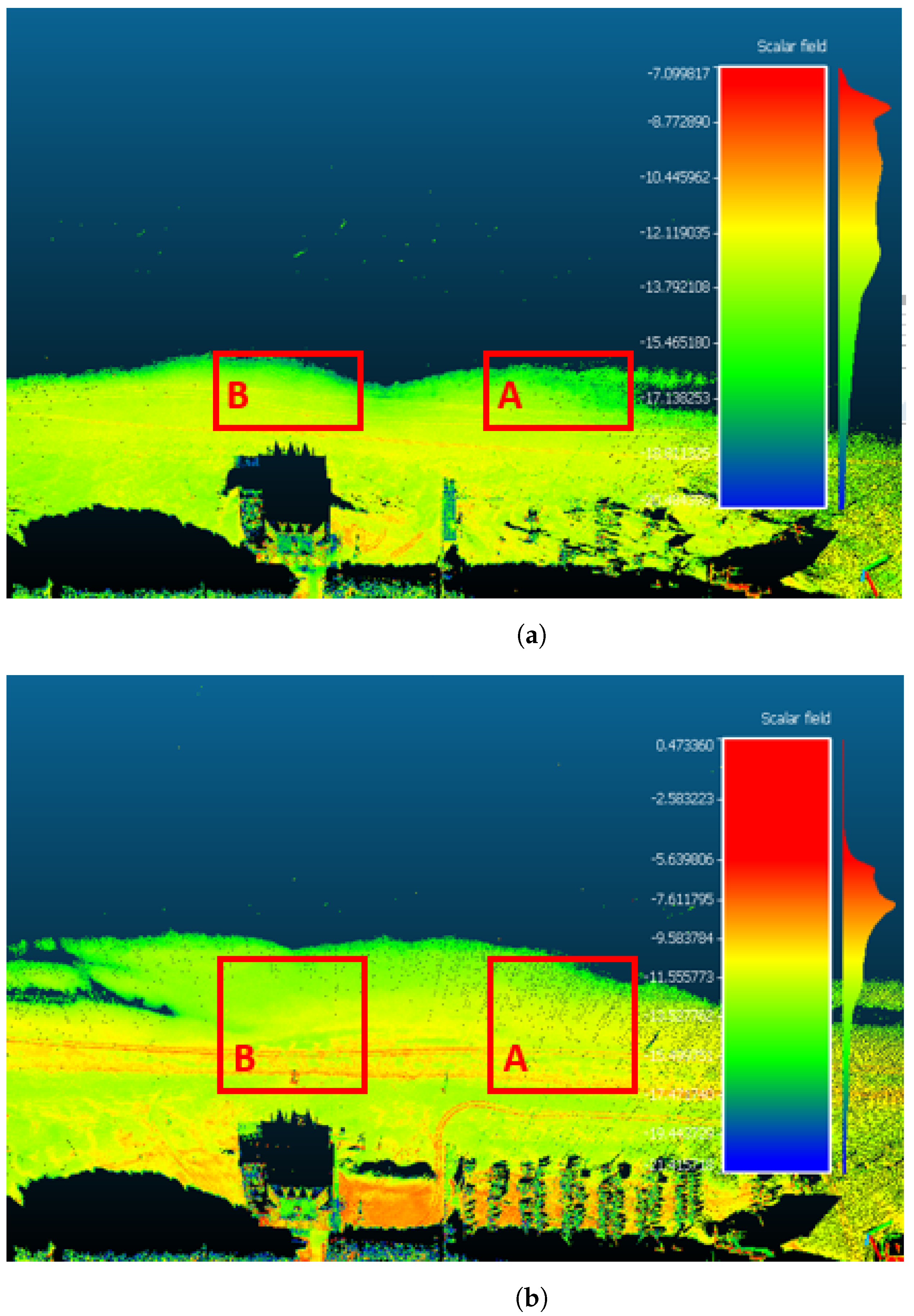
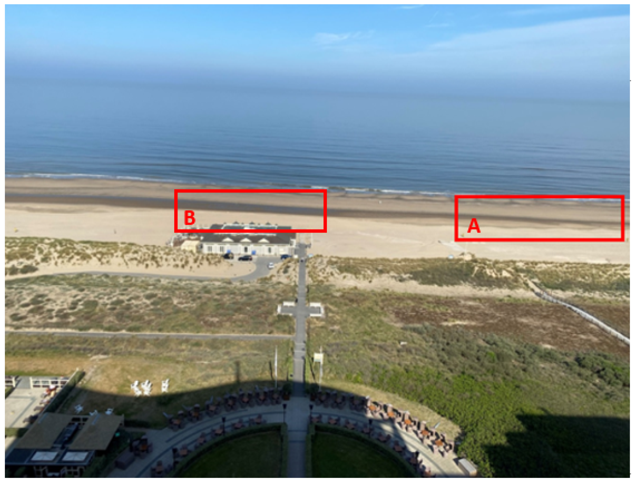
It was intended to collect data for two years. The field of view was ∼1 km by ∼300 m and contained parts of the dunes, the beach, and the intertidal zone during high and low tide. This yielded detailed information on the beach’s morphology and the waterline. Every hour, a dataset containing a 3D representation of the scanned area and the backscatter intensity was collected. Figure 2 shows the backscatter intensity of the TLS field of view during low- and high-tide conditions and provides an overview of the location of the study area. In situ measurements were collected at 7:00 a.m. (local time) on five different days between January and March 2020, at the same time as the passage of the Sentinel-1 satellites over the Dutch coast. The measurements were collected in an area with a length of 100 m and a variable width depending on the tide (70 to 130 m) (area A; see Figure 3).
The days of the surveys were characterized by the absence of rain and varying wind conditions (ranging from 5 to 14 m/s at the moment of the scan). Tidal conditions varied as well, affecting the area of the measurements; compare with Figure 2.
Each daily set of data points consisted of about 40 in situ probe measurements collected roughly 30 min after the time of the laser scan. Each in situ measurement included a soil moisture (%) value and was positioned with a precision of 1–2 cm using RTK-GPS. During the five days of the survey, more than 200 measurements were collected. Most of the measurements (128 data points were taken on three out of the five days in area A; cf. Figure 3) were used to approximate the new calibration curve. The remaining two days were used to validate the curve. A further theoretical study, which will be discussed in Section 2.3, also took a different area into account (area B; cf. Figure 3).

2.1. Permanent Laser Scanner

A TLS utilizes the round-trip time of an emitted laser beam to provide the range between the laser scanner and the backscattering object [72]. The Riegl VZ-2000 operates with an accuracy of 8 mm, where the accuracy is the degree of conformity of a measured quantity to its actual (true) value, and a precision—also called reproducibility or repeatability, which is the degree to which further measurements show the same result—of 5 mm [73] in the near-infrared, hence its usefulness for moisture retrieval; its wavelength is close to the water absorption peak of 1500 nm [38,74]. The laser beam’s divergence was 0.3 mrad, and its field of view was 100° horizontally and 360° vertically. Each point was associated with a horizontal angle ϕ and vertical angle θ . These coordinates were automatically converted into ( x , y , z ) coordinates relative to the TLS. High-resolution data correspond to an angular point spacing of 0.015°, which is a point spacing of about 10 cm at the water line. The scan was repeated every hour at a low resolution, which corresponded to 0.03° angular point spacing (about 30 cm point spacing at the water line, and about 3 cm in the dry area), closest to the TLS. Each data point contained ( x , y , z ) coordinates and reflectance. Low-resolution data points were used to find the relation with the in situ measurements. The reflectance provided by the TLS was a ratio of the actual amplitude of the target to the amplitude of a white flat target at the same range, oriented orthogonally to the beam axis, and with a size in excess of the laser footprint [73]. The reflectance is given in decibels (dB).

2.2. In Situ TDR Measurements

In situ moisture measurements were collected with a Trime-Pico32 sensor, which is a TDR device. Trime probes measure the conductivity and moisture in the same large soil volume [75]. The volumetric moisture is given as a percentage with a ±2% accuracy range for moisture values of 0 to 40% and ±3% for moisture values of 40 to 70%.
TDR probes need to be calibrated to achieve their best performance. They yield an average reading of the volumetric value over the entire probe length of 11 cm. Although the surface and near-surface samples follow similar moisture trends, in areas where the surface dries rapidly, the direct surface value could be most relevant [29]. Yang et al. [30] and Schmutz et al. [76] stated that the measurement resolution of the probe decreases as the active probe length is reduced, but there does not seem to be a significant decrease in accuracy. Schmutz et al. [76] reported that reducing the active probe length to 1.5 cm (from 6 cm at full length) increases the standard error of measurement from ± 1.0 to ± 1.9 % moisture content. Therefore, instead of the use of a dielectric foam, we decided to exploit the capability of the sensor to be buried in both horizontal and vertical orientations [75]. For each measurement, the sensor was horizontally buried in a ditch of 4 cm depth. In this way, it provided soil moisture measurements at a depth smaller than the case of the vertical orientation (11 cm). The sensor provides several default calibration settings depending on the type of soil to be analyzed. The calibration for sandy soils was used.
The consistency of the probe measurements was verified and validated through a comparison with the gravimetric method; cf. [77,78]. Soil samples at 2 mm from the surface were collected, weighed when wet, dried in an oven at 105 °C for 24 h, and reweighed to determine the dry sample weight. The moisture content, w, which is expressed as a percentage, is
w = w s w d w d ,
where w s and w d are the initial wet sample weight and the dried sample weight, respectively [76]. The moisture retrieved with the gravimetric method was then compared with the moisture measured by the probes at the same time and at the same location. Laboratory tests developed at the facilities of the Technische Universiteit Delft showed that the differences found between the moisture values evaluated with these two different methods were up to ± 1.0 % ; therefore, they were considered negligible in the present study.

2.3. Incidence Angle and Distance from the TLS

An aspect to be considered is the backscatter intensity (I) correction as a function of the range (R) from the source (TLS) and of the incidence angle ( θ ). The angle of incidence influences the maximum distance over which a TLS can accurately measure surface moisture [62], and it depends on the target’s physical properties and geometrical conditions [79]. For Nield [61] and Smit [62], the influence of the incidence angle was not relevant when using the TLS for soil moisture estimation on a sandy beach surface; Jin [69] considered this aspect relevant, and he carried out a series of indoor calibration experiments with the purpose of understanding the dependence of I on the incidence angle under the same gravimetric moisture conditions.
The relation between I, the range, and the incidence angle can be expressed with the simplified equation [69]:
I = ρ cos θ R 2 C
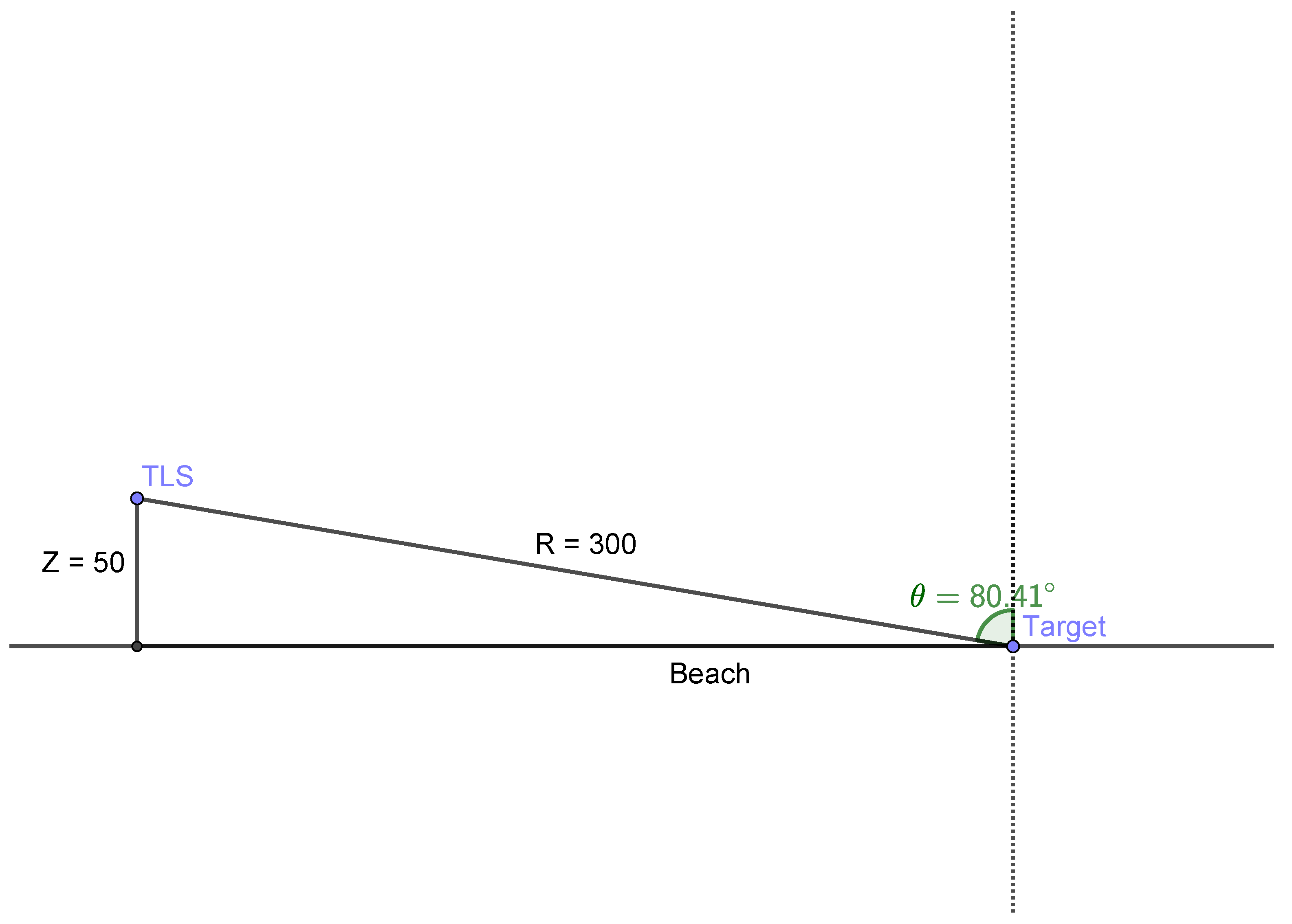
where I is the backscatter intensity given in magnitude, ρ stands for the reflectance of the target, and θ is the incidence angle. R is the range and C is a parameter describing the system and the atmospheric factors. In the present study, considering the relative position between the TLS and the study area (see Figure 3), it was possible to ignore the influence of the incidence angle. Equation (2) shows how I is linearly dependent on cos θ , which can be approximated as cos θ z / R , where z is the height difference between the study area and the TLS (source) position. Considering that z 50 m and that the range values are of the order of hundreds of meters ( R 300 m for site A), the characteristic values of θ were approximately 80 deg with respect to the considered sandy area (see Figure 4), with extremely limited variations on the beach.
The short-range configuration used by Jin [69] caused high variation of the incidence angle; therefore, it was not possible to consider cos θ as a constant, and the dependence of I on the incidence angle was not negligible.
Similar considerations could be made about range. Equation (2) shows how I depends on the range ( 1 / R 2 ). Considering the range of the present configuration (hundreds of meters), its variation caused minimal relative variation of 1 / R 2 . Nonetheless, it was possible to evaluate the correction factors when calculating the backscatter intensity in order to consider the influences of R and θ for different areas of interest. For instance, we wanted to estimate the soil moisture at two different targets located in the A and B areas of Figure 3 on the assumption that they had the same reflectance values ( ρ ). We could also consider C as a constant. For each target, we could consider:
I A R A 2 cos ( θ A ) = ρ C
I B R B 2 cos ( θ B ) = ρ C
where A and B refer to targets A and B, respectively. We obtain:
I B = R A 2 R B 2 cos ( θ B ) cos ( θ A ) I A

3. Methods

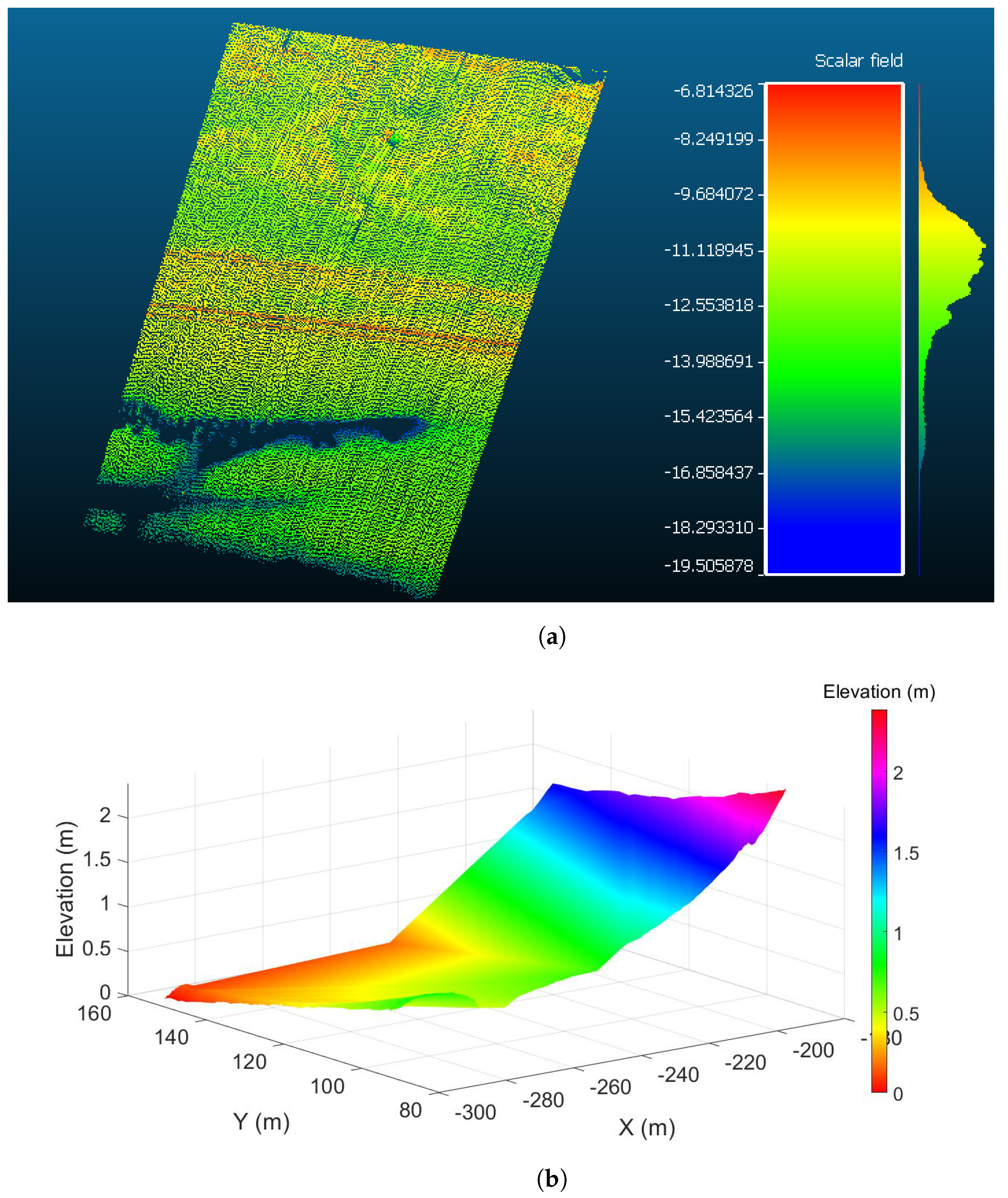
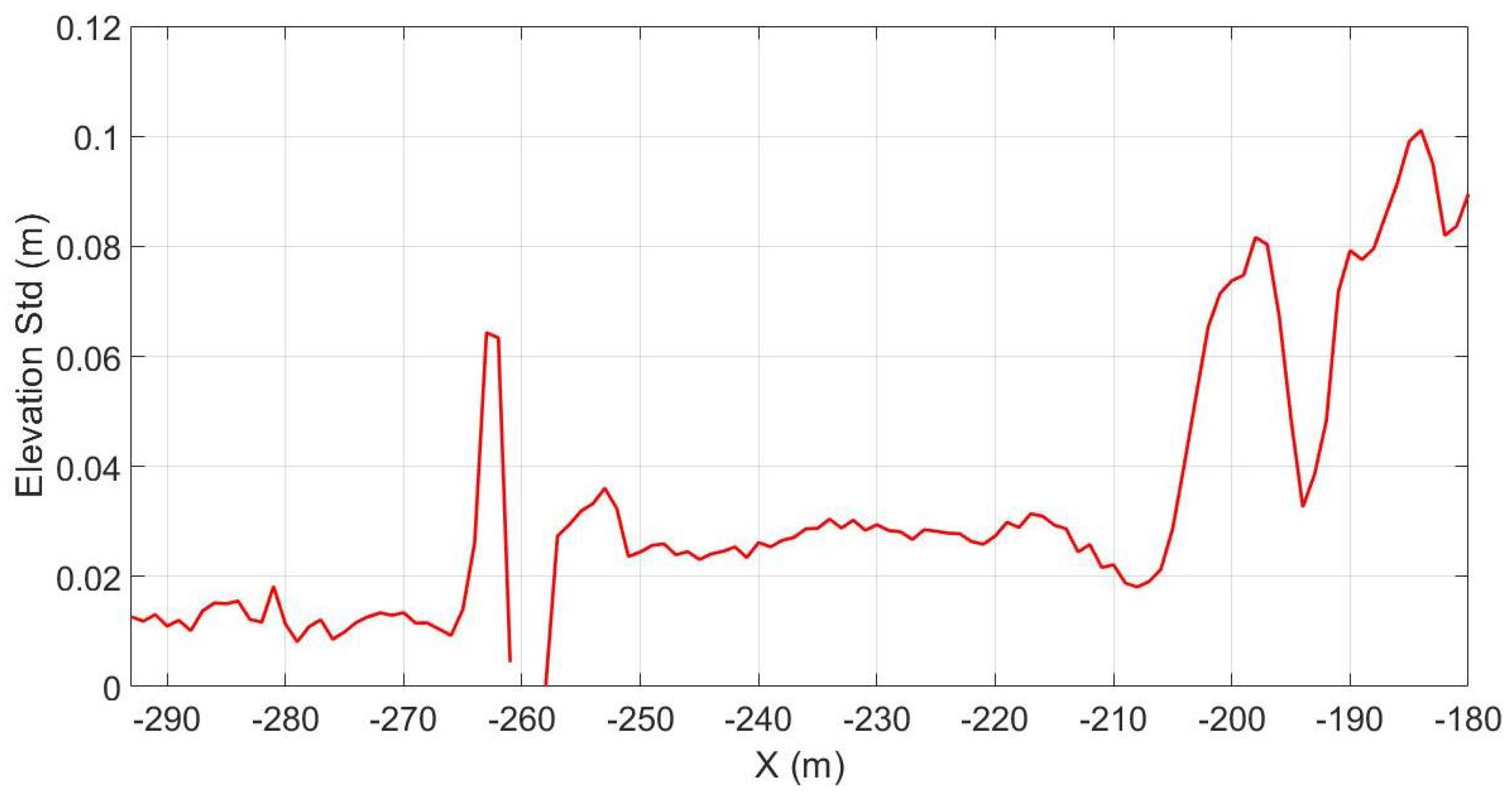
A calibration curve was obtained by comparing in situ moisture data (see Section 2.2) with the reflectance data measured by the TLS (see Section 2.1). The TLS ( x , y ) coordinates, initially relative to the TLS, were georeferenced in geocentric coordinates, which were latitudes and longitudes in an Earth-centered, Earth-fixed (ECEF) coordinate system. We matched each in situ moisture measurement with the closest reflectance measurement provided by the TLS. In situ measurements with a distance higher than 1 meter with respect to the closest laser point were excluded. This procedure allowed the exclusion from the calibration of all of the in situ measurements whose distance from a TLS point would have been too long to assume that the moisture remained constant [33]. In the study area, the moisture values were generally lower than 30%; therefore, thanks to the high TLS resolution, in situ data were associated to TLS points that were extremely close (within 6 cm) to the location of the measurement. The range of one meter was chosen as a good compromise for considering the measurements taken in areas with high moisture content in order to make the association reliable and to avoid excluding a high number of in situ measurements (see Section 4.1). For moisture values higher than 30%, the distance from the associated TLS data point was not reliable (even more than 5 m). This is related to the inability of the laser to detect wet areas when the water content is higher than 30%, and this can be ascribed to the fact that the sand surface is inundated by water, which absorbs the laser beam [62]. To remove erroneous data, 1 m was assumed as a threshold. This also allowed the exclusion of most of the data points with moisture greater than 30%. The remaining data points with moisture values greater than 30% were saturated [62]. The elevation profile (Figure 5) and its standard deviation (Figure 6) were used to evaluate outliers (e.g., people or tractors on the beach).
Overall, 128 of the in situ measurements taken on three of the five total days were used for the calibration. Data points considered to be outliers and with a distance greater than 1 m from the closest point measured by the laser were excluded (∼20% of the total measurements).

4. Results and Validation

Based on the implemented curve, which was proposed by Smit et al. [62] for a terrestrial laser scanner, a new calibration curve (see Figure 7) was assessed for moisture. The calibration curve—which interpolates pairs of associated data—was evaluated in the following form:
w ( b ) = w max w min 1 + exp ( k ( b k 2 ) ) + w max
where k = k 1 / k 3 , b is the reflectance measured by TLS (in (dB)), w max represents the saturation values assumed for moisture content w min , E c , min are the minimum detectable probe values for w (here, we assume these to be w min = 0 ), and k 1 , k 2 , and k 3 are constants to be determined. The data were interpolated by using a non-linear least squares method. As discussed above, the saturation value of the moisture content was set to 30%. The w calibration curve gave the following results for the interpolation coefficients: k 1 = 421.61 , k 2 = 12.46 , and k 3 = 240.30 . The calibration curve for the moisture in the present form gave an RMSE of 4.3% and an R-square of 0.86. An overview of the estimated values for the evaluated fitted curve is given in Table 1.

4.1. Validation

In the present form, the calibration curve is applicable for the area described in Section 2. As mentioned, this fitting curve was assessed by using data points collected over three days of surveys, and these were used as the predicted curve for a validation test. The validation test was conducted by using independent data points collected during two additional days of surveys; see Figure 8.
Of the 48 data points collected on this day, seven points were excluded because their distance was greater than 1 m from the closest point measured by the laser or because they were considered outliers. The data collected during this validation survey were used to evaluate the root-mean-square error (RMSE) with respect to the moisture calibration curve obtained in Section 4 (with the parameters shown in Table 1); the RMSE resulted in 4.1% and the mean error was 2.9%. A comparison of these values with the ones in Table 1 shows that they are consistent with the days used for calibrating the curve.
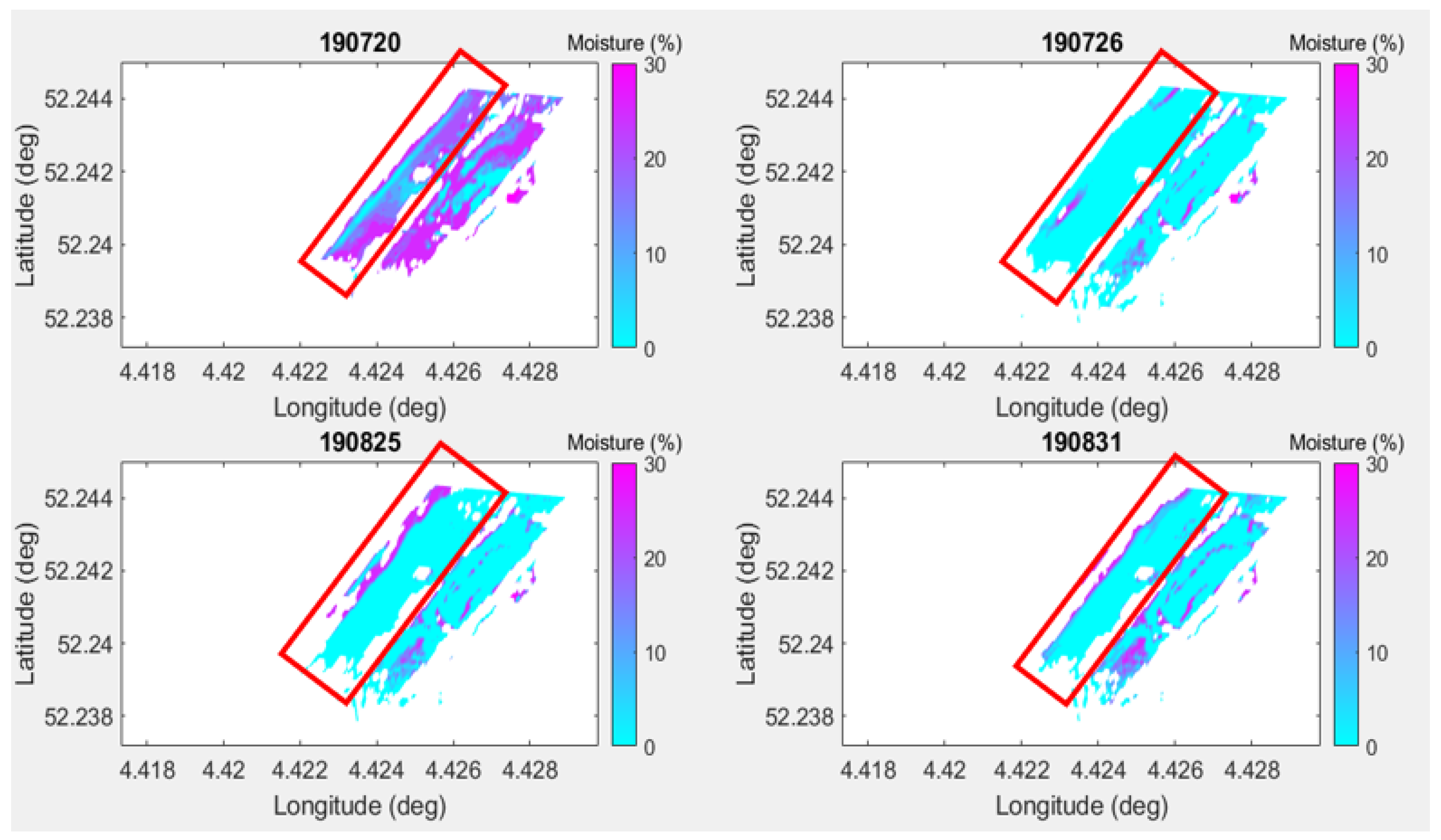
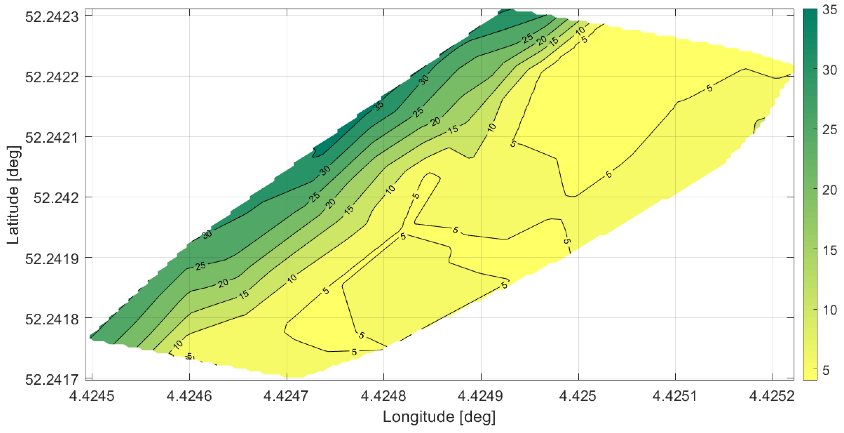
As discussed above, the distance of 1 m was considered as a good compromise for creating the association of in situ and laser data points to both assess the curve and validate it. We also evaluated how a shorter distance would decrease the RMSE: A 0.3 m distance gives an RMSE of 3.8% and a mean error of 2.7%. Unfortunately, in this study, a shorter distance would result in the exclusion of a high number of in situ measurements, and the remaining data points would be considered insufficient for the purpose of the validation. For a future investigation, a higher number of in situ measurements can be considered to be a better compromise. By applying the calibration curve, moisture maps of the area scanned by the laser on different days were evaluated. The moisture maps from four different days are presented in Figure 9. The moisture maps obtained using the calibration curve were compared with the maps interpolated using in situ data (Figure 10). The consistency of the obtained maps further proves how the permanent long-range TLS can be used for high-spatiotemporal-resolution maps, thus avoiding time-consuming surveys.
The scan from 20 July 2019 shows some anomalies in the backscatter values (values up to the saturation close to the foredune area) that cannot be ascribed to moisture. The hypothesis is that these anomalies can be attributed to the strong wind and, consequently, to the aeolian transport, which can affect the signal. The wind conditions were similar (from 2 to 4 m/s) for three of the four images represented. However, during the scan of 20 July 2019, the wind speed was >10 m/s. This phenomenon of backscatter anomalies was noticed on other days that were characterized by high wind speeds or by the presence of sea foam on the sand, e.g., after a storm.

4.2. Environmental and Meteorological Conditions

As shown in Figure 7, the predicted curve remained consistent in the entire considered range, and particularly when the reflection was lower than 15 dB, where the moisture presented the highest variability.
Rain and tidal conditions affect sandy soils in terms of soil moisture. A dedicated investigation was carried out in order to demonstrate how the calibration curves obtained under different conditions were consistent with the weather and tidal dataset; the moisture variation depending on rain and tidal conditions was analyzed. This test was performed on a day with increased precipitation. Precipitation data were acquired from a private weather station located in the analyzed area. Moisture maps were evaluated for each laser scan (every hour).
On the selected day, the highest tidal condition was reported at 15:53. The rain started at 16.30 and reached its peak at 19:30; afterwards, it decreased. A selection of the moisture maps is reported in Figure 11, where both the tidal condition (increasing tide until 15:01, then decreasing) and the increasing precipitation rate (maximum value at 19:01) can be seen.
The results of this study can be further investigated for a multi-temporal analysis of the moisture variation along the beach.

5. Conclusions

The present study showed how a permanent TLS (RIEGL-VZ2000) is a highly suited technique for accurately estimating surface moisture variations in a coastal environment with high spatiotemporal resolution over a wide area. The use of a permanent TLS, with its original setting on top of a tall building and overlooking a wide sandy area, allowed moisture analysis over a large field of view, including a swash zone, where the moisture content had the highest variability. Moreover, with its permanent position in the area of interest, it guaranteed continuous and high-spatiotemporal-resolution information on the area, with the main advantage of collecting a significant amount of data, thus avoiding time-consuming and expensive in situ experiments.
A new calibration curve was assessed in order to evaluate soil moisture as a TLS backscatter function. The TLS reflectance and probe measurements showed a robust correlation up to 30% moisture content with a root-mean-square error (RMSE) of 4.3% and a coefficient of determination (R-square) of 0.86 for soil moisture. These values, which were evaluated by using a long-range permanent laser scanner, are consistent with the findings of previous literature in which TLS located directly in the study area was used.
The calibration curve was validated and tested under different circumstances in order to consider a different angle of view from the TLS and different wind, rain, and tidal conditions. It was showed how the validity of the assessed relations persisted under these conditions, and this can be further investigated in future studies thanks to the availability of a large temporal dataset collected by the permanent TLS.
Relevant applications of the obtained calibration curve include the exploitation of SAR data; considering their sensitivity to soil moisture, the large amount of in situ data obtained with the TLS could be used to evaluate new calibration curves that are able to relate SAR backscatter to soil moisture.

Author Contributions

V.D.B. provided the conception of the present research, planned the in-situ beach measurements, performed the data processing, the data analyses and validation, the production of maps and wrote the majority of the manuscript. S.E.V. provided TLS pre-processed data. R.F.H. provided guidance and helped with the conception of this research. R.F.H. and S.E.V. provided supervision, review and editing of the manuscript. All authors have read and agreed to the published version of the manuscript.

Funding

This research received no external funding.

Acknowledgments

For the present work, V.D.B. and R.H. were supported by the Mitsubishi Electric Corporation through the Detecting, identifying, and classifying sandy soils using satellite SAR data project. The usage of the terrestrial laser scanner was financed by the ERC-Advanced grant 291206—Nearshore Monitoring and Modeling and the CoastScan project 2018/STW/00505023. The authors wish to thank the owner and manager of the Hotel Huis ter Duin (www.huisterduin.com, accessed on 21 April 2021) in Noordwijk for supporting the research with the use of the hotel for the measurements. Additional thanks goes to Baars-CIPRO (www.baars-cipro.nl, accessed on 21 April 2021) for their advice, construction of the measuring frame, and operational support.

Conflicts of Interest

The authors declare that they have no known competing financial interests of personal relationships that could have appeared to influence the work reported in this paper.

References

  1. Keijsers, J.; De Groot, A.; Riksen, M. Modeling the biogeomorphic evolution of coastal dunes in response to climate change. J. Geophys. Res. Earth Surf. 2016, 121, 1161–1181. [Google Scholar] [CrossRef] [Green Version]
  2. Nickling, W.G.; Davidson-Arnott, R. Beaches and coastal sand dunes. In Proceedings of the Canadian Symposium on Coastal Sand Dunes, Guelph, ON, Canada, 12–14 September 1990; p. 1. [Google Scholar]
  3. Sherman, D.J.; Bauer, B.O. Dynamics of beach-dune systems. Prog. Phys. Geogr. 1993, 17, 413–447. [Google Scholar] [CrossRef]
  4. Bauer, B.O.; Davidson-Arnott, R.G. A general framework for modeling sediment supply to coastal dunes including wind angle, beach geometry, and fetch effects. Geomorphology 2003, 49, 89–108. [Google Scholar] [CrossRef]
  5. Anthony, E.J.; Ruz, M.H.; Vanhée, S. Aeolian sand transport over complex intertidal bar-trough beach topography. Geomorphology 2009, 105, 95–105. [Google Scholar] [CrossRef]
  6. Namikas, S.; Edwards, B.; Bitton, M.; Booth, J.; Zhu, Y. Temporal and spatial variabilities in the surface moisture content of a fine-grained beach. Geomorphology 2010, 114, 303–310. [Google Scholar] [CrossRef]
  7. Van der Wal, D. Effects of fetch and surface texture on aeolian sand transport on two nourished beaches. J. Arid Environ. 1998, 39, 533–547. [Google Scholar] [CrossRef]
  8. Neuman, C.M.; Scott, M.M. A wind tunnel study of the influence of pore water on aeolian sediment transport. J. Arid Environ. 1998, 39, 403–419. [Google Scholar] [CrossRef]
  9. Jackson, N.L.; Nordstrom, K.F. Effects of time-dependent moisture content of surface sediments on aeolian transport rates across a beach, Wildwood, New Jersey, USA. Earth Surf. Process. Landf. J. Br. Geomorphol. Group 1997, 22, 611–621. [Google Scholar] [CrossRef]
  10. Wiggs, G.; Baird, A.; Atherton, R. The dynamic effects of moisture on the entrainment and transport of sand by wind. Geomorphology 2004, 59, 13–30. [Google Scholar] [CrossRef]
  11. Delgado-Fernandez, I. Meso-scale modelling of aeolian sediment input to coastal dunes. Geomorphology 2011, 130, 230–243. [Google Scholar] [CrossRef] [Green Version]
  12. Sarre, R. Evaluation of aeolian sand transport equations using intertidal zone measurements, Saunton Sands, England. Sedimentology 1988, 35, 671–679. [Google Scholar] [CrossRef]
  13. Namikas, S.L.; Sherman, D.J. A review of the effects of surface moisture content on aeolian sand transport. In Desert Aeolian Processes; Springer: Berlin, Germany, 1995; pp. 269–293. [Google Scholar]
  14. Cornelis, W.; Gabriels, D. The effect of surface moisture on the entrainment of dune sand by wind: An evaluation of selected models. Sedimentology 2003, 50, 771–790. [Google Scholar] [CrossRef]
  15. McKenna-Neuman, C.; Nickling, W. A theoretical and wind tunnel investigation of the effect of capillary water on the entrainment of sediment by wind. Can. J. Soil Sci. 1989, 69, 79–96. [Google Scholar] [CrossRef]
  16. Kaleita, A.L.; Heitman, J.L.; Logsdon, S.D. Field calibration of the theta probe for Des Moines lobe soils. Appl. Eng. Agric. 2005, 21, 865–870. [Google Scholar] [CrossRef] [Green Version]
  17. Brakenhoff, L.B.; Smit, Y.; Donker, J.J.; Ruessink, G. Tide-induced variability in beach surface moisture: Observations and modelling. Earth Surf. Process. Landf. 2019, 44, 317–330. [Google Scholar] [CrossRef]
  18. Atherton, R.J.; Baird, A.J.; Wiggs, G.F. Inter-tidal dynamics of surface moisture content on a meso-tidal beach. J. Coast. Res. 2001, 17, 482–489. [Google Scholar]
  19. Schmutz, P.P.; Namikas, S.L. Measurement and modeling of moisture content above an oscillating water table: Implications for beach surface moisture dynamics. Earth Surf. Process. Landf. 2013, 38, 1317–1325. [Google Scholar] [CrossRef]
  20. Famiglietti, J.S.; Ryu, D.; Berg, A.A.; Rodell, M.; Jackson, T.J. Field observations of soil moisture variability across scales. Water Resour. Res. 2008, 44. [Google Scholar] [CrossRef] [Green Version]
  21. Hájek, M.; Hájková, P.; Kočí, M.; Jiroušek, M.; Mikulášková, E.; Kintrová, K. Do we need soil moisture measurements in the vegetation–environment studies in wetlands? J. Veg. Sci. 2013, 24, 127–137. [Google Scholar] [CrossRef]
  22. Yang, X.; Yu, Y.; Li, M. Estimating soil moisture content using laboratory spectral data. J. For. Res. 2019, 30, 1073–1080. [Google Scholar] [CrossRef]
  23. Zhao, Y.; Peth, S.; Hallett, P.; Wang, X.; Giese, M.; Gao, Y.; Horn, R. Factors controlling the spatial patterns of soil moisture in a grazed semi-arid steppe investigated by multivariate geostatistics. Ecohydrology 2011, 4, 36–48. [Google Scholar] [CrossRef]
  24. Bretreger, D.; Yeo, I.Y.; Melchers, R. Terrain wetness indices derived from LiDAR to inform soil moisture and corrosion potential for underground infrastructure. Sci. Total Environ. 2021, 756, 144138. [Google Scholar] [CrossRef] [PubMed]
  25. Walker, I.; Davidson-Arnott, R.; Hesp, P.; Bauer, B.; Ollerhead, J. Mean flow and turbulence responses in airflow over foredunes: New insights from recent research. J. Coast. Res. 2009, I, 366–370. [Google Scholar]
  26. Hoonhout, B.M.; Vries, S.D. A process-based model for aeolian sediment transport and spatiotemporal varying sediment availability. J. Geophys. Res. Earth Surf. 2016, 121, 1555–1575. [Google Scholar] [CrossRef]
  27. Hoonhout, B.; de Vries, S. Field measurements on spatial variations in aeolian sediment availability at the Sand Motor mega nourishment. Aeol. Res. 2017, 24, 93–104. [Google Scholar] [CrossRef] [Green Version]
  28. Cohn, N.; Ruggiero, P.; de Vries, S.; Kaminsky, G.M. New insights on coastal foredune growth: The relative contributions of marine and aeolian processes. Geophys. Res. Lett. 2018, 45, 4965–4973. [Google Scholar] [CrossRef]
  29. Nield, J.M.; Wiggs, G.F.; Squirrell, R.S. Aeolian sand strip mobility and protodune development on a drying beach: Examining surface moisture and surface roughness patterns measured by terrestrial laser scanning. Earth Surf. Process. Landf. 2011, 36, 513–522. [Google Scholar] [CrossRef]
  30. Yang, Y.; Davidson-Arnott, R.G. Rapid measurement of surface moisture content on a beach. J. Coast. Res. 2005, 21, 447–452. [Google Scholar] [CrossRef]
  31. Davidson-Arnott, R.G.; Yang, Y.; Ollerhead, J.; Hesp, P.A.; Walker, I.J. The effects of surface moisture on aeolian sediment transport threshold and mass flux on a beach. Earth Surf. Process. Landf. J. Br. Geomorphol. Res. Group 2008, 33, 55–74. [Google Scholar] [CrossRef]
  32. Dwevedi, A.; Kumar, P.; Kumar, P.; Kumar, Y.; Sharma, Y.K.; Kayastha, A.M. Soil sensors: Detailed insight into research updates, significance, and future prospects. In New Pesticides and Soil Sensors; Elsevier: Hoboken, NJ, USA, 2017; pp. 561–594. [Google Scholar]
  33. Edwards, B.L.; Namikas, S.L. Small-scale variability in surface moisture on a fine-grained beach: Implications for modeling aeolian transport. Earth Surf. Process. Land. 2009, 34, 1333–1338. [Google Scholar] [CrossRef]
  34. Sheng, W.; Zhou, R.; Sadeghi, M.; Babaeian, E.; Robinson, D.A.; Tuller, M.; Jones, S.B. A TDR array probe for monitoring near-surface soil moisture distribution. Vadose Zone J. 2017, 16, 1–8. [Google Scholar] [CrossRef]
  35. Edwards, B.L.; Schmutz, P.P.; Namikas, S.L. Comparison of surface moisture measurements with depth-integrated moisture measurements on a fine-grained beach. J. Coast. Res. 2013, 29, 1284–1291. [Google Scholar]
  36. Ångström, A. The albedo of various surfaces of ground. Geogr. Ann. 1925, 7, 323–342. [Google Scholar]
  37. Twomey, S.A.; Bohren, C.F.; Mergenthaler, J.L. Reflectance and albedo differences between wet and dry surfaces. Appl. Opt. 1986, 25, 431–437. [Google Scholar] [CrossRef] [PubMed]
  38. Lobell, D.B.; Asner, G.P. Moisture effects on soil reflectance. Soil Sci. Soc. Am. J. 2002, 66, 722–727. [Google Scholar] [CrossRef]
  39. Philpot, W. Spectral reflectance of wetted soils. Proc. ASD IEEE GRS 2010, 2, 1–12. [Google Scholar]
  40. Nolet, C.; Poortinga, A.; Roosjen, P.; Bartholomeus, H.; Ruessink, G. Measuring and modeling the effect of surface moisture on the spectral reflectance of coastal beach sand. PLoS ONE 2014, 9, e112151. [Google Scholar] [CrossRef]
  41. Williams, R.; Brasington, J.; Vericat, D.; Hicks, D. Hyperscale terrain modelling of braided rivers: Fusing mobile terrestrial laser scanning and optical bathymetric mapping. Earth Surf. Process. Landf. 2014, 39, 167–183. [Google Scholar] [CrossRef]
  42. Darke, I.; Davidson-Arnott, R.; Ollerhead, J. Measurement of beach surface moisture using surface brightness. J. Coast. Res. 2009, 25, 248–256. [Google Scholar] [CrossRef]
  43. Delgado-Fernandez, I.; Davidson-Arnott, R. Sediment input to foredunes: Description and frequency of transport events at Greenwich Dunes, PEI, Canada. J. Coast. Res. 2009, 1, 302–306. [Google Scholar]
  44. McKenna Neuman, C.; Langston, G. Measurement of water content as a control of particle entrainment by wind. Earth Surf. Process. Landf. J. Br. Geomorphol. Res. Group 2006, 31, 303–317. [Google Scholar] [CrossRef]
  45. Lookingbill, T.; Urban, D. An empirical approach towards improved spatial estimates of soil moisture for vegetation analysis. Landsc. Ecol. 2004, 19, 417–433. [Google Scholar] [CrossRef]
  46. Jaboyedoff, M.; Oppikofer, T.; Abellán, A.; Derron, M.H.; Loye, A.; Metzger, R.; Pedrazzini, A. Use of LIDAR in landslide investigations: A review. Nat. Hazards 2012, 61, 5–28. [Google Scholar] [CrossRef] [Green Version]
  47. Bretreger, D.; Yeo, I.Y.; Melchers, R. LiDAR derived terrain wetness indices to infer soil moisture above underground pipelines. Int. J. Smart Sens. Intell. Syst. 2020, 13. [Google Scholar] [CrossRef] [Green Version]
  48. Kemppinen, J.; Niittynen, P.; Riihimäki, H.; Luoto, M. Modelling soil moisture in a high-latitude landscape using LiDAR and soil data. Earth Surf. Process. Landf. 2018, 43, 1019–1031. [Google Scholar] [CrossRef]
  49. Hardy, A.J.; Barr, S.L.; Mills, J.P.; Miller, P.E. Characterising soil moisture in transport corridor environments using airborne LIDAR and CASI data. Hydrol. Process. 2012, 26, 1925–1936. [Google Scholar] [CrossRef]
  50. Wehr, A.; Lohr, U. Airborne laser scanning—An introduction and overview. ISPRS J. Photogramm. Remote Sens. 1999, 54, 68–82. [Google Scholar] [CrossRef]
  51. Leempoel, K.; Parisod, C.; Geiser, C.; Daprà, L.; Vittoz, P.; Joost, S. Very high-resolution digital elevation models: Are multi-scale derived variables ecologically relevant? Methods Ecol. Evolut. 2015, 6, 1373–1383. [Google Scholar] [CrossRef]
  52. Jiang, Y.; Weng, Q. Estimation of hourly and daily evapotranspiration and soil moisture using downscaled LST over various urban surfaces. GISci. Remote Sens. 2017, 54, 95–117. [Google Scholar] [CrossRef]
  53. Baldwin, D.; Naithani, K.J.; Lin, H. Combined soil-terrain stratification for characterizing catchment-scale soil moisture variation. Geoderma 2017, 285, 260–269. [Google Scholar] [CrossRef] [Green Version]
  54. Li, X.; Liu, S.; Xiao, Q.; Ma, M.; Jin, R.; Che, T.; Wang, W.; Hu, X.; Xu, Z.; Wen, J.; et al. A multiscale dataset for understanding complex eco-hydrological processes in a heterogeneous oasis system. Sci. Data 2017, 4, 1–11. [Google Scholar] [CrossRef] [PubMed] [Green Version]
  55. Vosselman, G.; Maas, H.G. Airborne and Terrestrial Laser Scanning; CRC Press: Boca Raton, FL, USA, 2010. [Google Scholar]
  56. French, J.; Burningham, H. Coastal geomorphology: Trends and challenges. Prog. Phys. Geogr. 2009, 33, 117–129. [Google Scholar] [CrossRef]
  57. Zelaya Wziątek, D.; Terefenko, P.; Kurylczyk, A. Multi-temporal cliff erosion analysis using airborne laser scanning surveys. Remote Sens. 2019, 11, 2666. [Google Scholar] [CrossRef] [Green Version]
  58. de Sanjosé Blasco, J.J.; Serrano-Cañadas, E.; Sánchez-Fernández, M.; Gómez-Lende, M.; Redweik, P. Application of Multiple Geomatic Techniques for Coastline Retreat Analysis: The Case of Gerra Beach (Cantabrian Coast, Spain). Remote Sens. 2020, 12, 3669. [Google Scholar] [CrossRef]
  59. Kaasalainen, S.; Niittymaki, H.; Krooks, A.; Koch, K.; Kaartinen, H.; Vain, A.; Hyyppa, H. Effect of target moisture on laser scanner intensity. IEEE Trans. Geosci. Remote Sens. 2009, 48, 2128–2136. [Google Scholar] [CrossRef]
  60. Tan, K.; Chen, J.; Zhang, W.; Liu, K.; Tao, P.; Cheng, X. Estimation of soil surface water contents for intertidal mudflats using a near-infrared long-range terrestrial laser scanner. ISPRS J. Photogramm. Remote Sens. 2020, 159, 129–139. [Google Scholar] [CrossRef]
  61. Nield, J.M.; King, J.; Jacobs, B. Detecting surface moisture in aeolian environments using terrestrial laser scanning. Aeol. Res. 2014, 12, 9–17. [Google Scholar] [CrossRef]
  62. Smit, Y.; Ruessink, G.; Brakenhoff, L.B.; Donker, J.J. Measuring spatial and temporal variation in surface moisture on a coastal beach with a near-infrared terrestrial laser scanner. Aeol. Res. 2018, 31, 19–27. [Google Scholar] [CrossRef]
  63. Ruessink, G.; Brakenhoff, L.; van Maarseveen, M. Measurement of surface moisture using infra-red terrestrial laser scanning. In EGU General Assembly Conference Abstracts; NASA: Washington, DC, USA, 2014; p. 2797. [Google Scholar]
  64. Kukko, A.; Kaasalainen, S.; Litkey, P. Effect of incidence angle on laser scanner intensity and surface data. Appl. Opt. 2008, 47, 986–992. [Google Scholar] [CrossRef]
  65. Franceschi, M.; Teza, G.; Preto, N.; Pesci, A.; Galgaro, A.; Girardi, S. Discrimination between marls and limestones using intensity data from terrestrial laser scanner. ISPRS J. Photogramm. Remote Sens. 2009, 64, 522–528. [Google Scholar] [CrossRef]
  66. Kaasalainen, S.; Kukko, A.; Lindroos, T.; Litkey, P.; Kaartinen, H.; Hyyppa, J.; Ahokas, E. Brightness measurements and calibration with airborne and terrestrial laser scanners. IEEE Trans. Geosci. Remote Sens. 2008, 46, 528–534. [Google Scholar] [CrossRef]
  67. González-Jorge, H.; Gonzalez-Aguilera, D.; Rodriguez-Gonzalvez, P.; Arias, P. Monitoring biological crusts in civil engineering structures using intensity data from terrestrial laser scanners. Constr. Build. Mater. 2012, 31, 119–128. [Google Scholar] [CrossRef]
  68. Kaasalainen, S.; Jaakkola, A.; Kaasalainen, M.; Krooks, A.; Kukko, A. Analysis of incidence angle and distance effects on terrestrial laser scanner intensity: Search for correction methods. Remote Sens. 2011, 3, 2207–2221. [Google Scholar] [CrossRef] [Green Version]
  69. Jin, J.; De Sloover, L.; Verbeurgt, J.; Stal, C.; Deruyter, G.; Montreuil, A.L.; De Maeyer, P.; De Wulf, A. Measuring Surface Moisture on a Sandy Beach based on Corrected Intensity Data of a Mobile Terrestrial LiDAR. Remote Sens. 2020, 12, 209. [Google Scholar] [CrossRef] [Green Version]
  70. Vos, S.; Lindenbergh, R.; de Vries, S.; Aagaard, T.; Deigaard, R.; Fuhrman, D. Coastscan: Continuous monitoring of coastal change using terrestrial laser scanning. In Proceedings of the Coastal Dynamics, Helsingor, Danmark, 12–16 June 2017; pp. 12–16. [Google Scholar]
  71. Eisma, D. Composition, origin and distribution of Dutch coastal sands between Hoek van Holland and the island of Vlieland. Neth. J. Sea Res. 1968, 4, 123–267. [Google Scholar] [CrossRef] [Green Version]
  72. Wagner, W.; Ullrich, A.; Ducic, V.; Melzer, T.; Studnicka, N. Gaussian decomposition and calibration of a novel small-footprint full-waveform digitising airborne laser scanner. ISPRS J. Photogramm. Remote Sens. 2006, 60, 100–112. [Google Scholar] [CrossRef]
  73. RIEGL. Data Sheet, RIEGL VZ-2000; RIEGL: Horn, Austria, 2000. [Google Scholar]
  74. Singh, J.; Levick, S.R.; Guderle, M.; Schmullius, C. Moving from plot-based to hillslope-scale assessments of savanna vegetation structure with long-range terrestrial laser scanning (LR-TLS). Int. J. Appl. Earth Obs. Geoinf. 2020, 90, 102070. [Google Scholar] [CrossRef]
  75. IMKO. Manual TRIME-PICO 64/32; IMKO Micromodultechnik GmbH: Ettlingen, Germany, 2017. [Google Scholar]
  76. Schmutz, P.P.; Namikas, S.L. Utility of the Delta-T Theta Probe for obtaining surface moisture measurements from beaches. J. Coast. Res. 2011, 27, 478–484. [Google Scholar]
  77. Hillel, D. Soil and Water: Physical Principles and Processes; Elsevier: Hoboken, NJ, USA, 2012. [Google Scholar]
  78. Davidson-Arnott, R.; Bauer, B.; Houser, C. Introduction to Coastal Processes and Geomorphology; Cambridge University Press: Cambridge, UK, 2019. [Google Scholar]
  79. Pesci, A.; Teza, G. Effects of surface irregularities on intensity data from laser scanning: An experimental approach. Ann. Geophys. 2008, 51, 839–848. [Google Scholar]
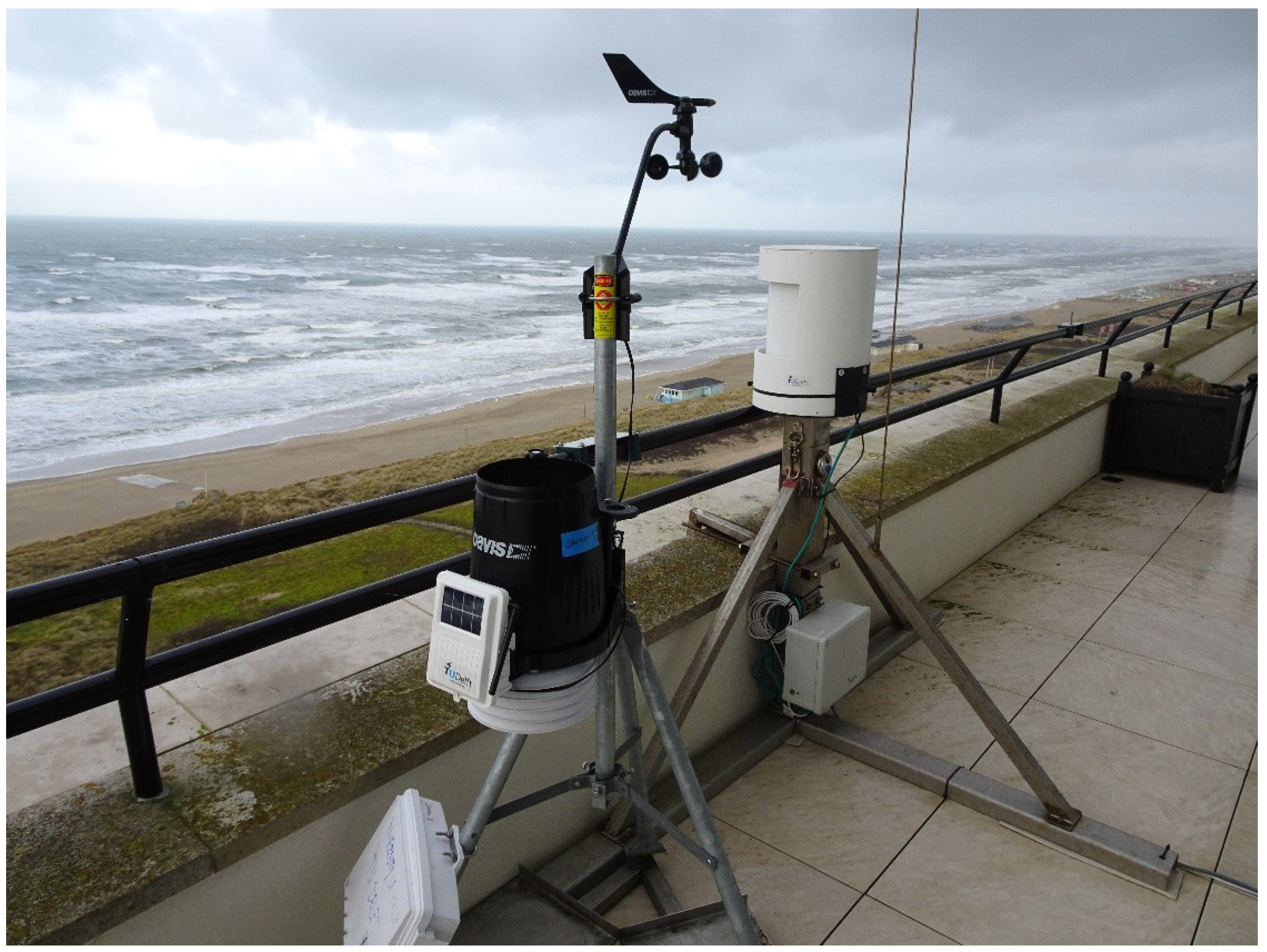
Figure 1. TLS and the weather station installed on the upper balcony of the Huis ter Duin Hotel, Noordwijk, the Netherlands.
Remotesensing 13 01645 g001
Figure 2. View of the backscatter intensity (dB) of the two fieldwork areas. (a): High-tide conditions (14 July 2019, 8:02 a.m.). (b): Low-tide conditions (12 October 2019, 8:02 a.m.).
Remotesensing 13 01645 g002
Figure 3. Partial view of the TLS on the beach of Noordwijk and locations of the fieldwork.
Remotesensing 13 01645 g003
Figure 4. TLS geometry on the beach of Noordwijk for a target located in the fieldwork area (A). Similar values occurred for other areas located in the TLS’s field of view (e.g., area B).
Remotesensing 13 01645 g004
Figure 5. (a) Point-cloud overview of a section of the scanned area with backscatter intensity (dB). The top of the image corresponds to the end of the dune area; the bottom corresponds to the swash zone. The areas without data points are due to the presence of backwater on the sand surface following high tide. The shadow of a building can be seen in the top-right corner. (b) Elevation profile (m) of the same section. X and Y are shown in TLS coordinates and represent the distance (m) from the TLS; X = 180 m corresponds to the end of the dune area; X = 300 m corresponds to the swash zone.
Remotesensing 13 01645 g005
Figure 6. Standard deviation of the beach elevation evaluated in the area shown in Figure 5. The standard deviation was evaluated within 1x80m transects parallel to the coastline. High variation in the standard deviation can be seen at the end of the dune area ( X = 180 to 210 m), corresponding to an area with high surface roughness, and in the backwater area ( X = 260 m).
Remotesensing 13 01645 g006
Figure 7. Soil moisture calibration curve assessed with data points measured over 3 days of surveying.
Remotesensing 13 01645 g007
Figure 8. In situ moisture data points used for validating. The moisture fitting curve (i.e., the predicted moisture curve obtained by using Equation (6) with the coefficients reported in Table 1).
Remotesensing 13 01645 g008
Figure 9. Moisture map of the area scanned by the laser on 20 July 2019, 26 July 2019, 25 July 2019, and 31 August 2019 at 8:00 a.m. The beach areas are shown in the red rectangles, with different widths depending on the tide. The back and foredune areas (right bottom) and the shadows of the dunes (with no cloud points) are included in the present maps, but their moisture was not investigated. The turquoise color in the beach areas indicates a low surface moisture content. Toward the sea, the surface moisture increases, reaching a saturation of 30%. This does not occur in the image evaluated on 20 July 2019.
Remotesensing 13 01645 g009
Figure 10. Contour map of the surface moisture in the study area during the in situ measurements collected on 30 January 2020 at the same time that Sentinel-1 passed over Noordwijk (7:08 a.m.).
Remotesensing 13 01645 g010
Figure 11. Selection of moisture maps evaluated on 12 October 2019. For each image, the time is reported on top as HHMMSS. The area of interest is shown in the red rectangle. Both the tidal condition (increasing tide until 15:01, then decreasing) and the increasing precipitation rate (maximum value at 19:01) can be seen in the masks. The top three images are characterized by the absence of rain and an increasing tidal condition. The image at 15:01:41 represents the highest tidal condition, where part of the beach area is covered by seawater and the moisture reaches the saturation value (30%). After that, the moisture starts decreasing again with the lowering of the tide. The lower images show the increasing precipitation rate: The moisture value of the sandy area that is not affected by the tide, which used to be in the range of 0–5%, increases to 10–15% at 19:01:46, when the precipitation rate is the highest. At 21:01:46, the moisture values are lower again.
Remotesensing 13 01645 g011
Table 1. Estimated parameter values of the soil moisture fitting curve in Equation (6) based on the in situ observations.
Parameter Value
wRMSER-Square k 1 k 2 k 3 w min w max
4.3 % 0.86 421.61 12.46 240.30 0 30 %
Publisher’s Note: MDPI stays neutral with regard to jurisdictional claims in published maps and institutional affiliations.