Article

Machine Learning Based Algorithms for Global Dust Aerosol Detection from Satellite Images: Inter-Comparisons and Evaluation

1
Department of Atmospheric Sciences, Texas A&M University, College Station, TX 77840, USA
2
Joint Center for Earth Systems Technology, University of Maryland, Baltimore County, Baltimore, MD 21250, USA
3
Climate and Radiation Laboratory (613), NASA Goddard Space Flight Center, Greenbelt, MD 20771, USA
4
Department of Occupational and Environmental Health, University of Oklahoma, Oklahoma City, OK 73019, USA
5
I M Systems Group Inc., Rockville, MD 20852, USA
6
Center for Satellite Applications and Research, National Oceanic and Atmospheric Administration, College Park, MD 20740, USA
7
Department of Information Systems, University of Maryland, Baltimore County, Baltimore, MD 21250, USA
8
Department of Physics, University of Maryland, Baltimore County, Baltimore, MD 21250, USA
*
Author to whom correspondence should be addressed.
Remote Sens. 2021, 13(3), 456; https://doi.org/10.3390/rs13030456
Submission received: 6 December 2020 / Revised: 15 January 2021 / Accepted: 21 January 2021 / Published: 28 January 2021
(This article belongs to the Special Issue Active and Passive Remote Sensing of Aerosols and Clouds)

Abstract

:
Identifying dust aerosols from passive satellite images is of great interest for many applications. In this study, we developed five different machine-learning (ML) based algorithms, including Logistic Regression, K Nearest Neighbor, Random Forest (RF), Feed Forward Neural Network (FFNN), and Convolutional Neural Network (CNN), to identify dust aerosols in the daytime satellite images from the Visible Infrared Imaging Radiometer Suite (VIIRS) under cloud-free conditions on a global scale. In order to train the ML algorithms, we collocated the state-of-the-art dust detection product from the Cloud-Aerosol Lidar with Orthogonal Polarization (CALIOP) with the VIIRS observations along the CALIOP track. The 16 VIIRS M-band observations with the center wavelength ranging from deep blue to thermal infrared, together with solar-viewing geometries and pixel time and locations, are used as the predictor variables. Four different sets of training input data are constructed based on different combinations of VIIRS pixel and predictor variables. The validation and comparison results based on the collocated CALIOP data indicate that the FFNN method based on all available predictor variables is the best performing one among all methods. It has an averaged dust detection accuracy of about 81%, 89%, and 85% over land, ocean and whole globe, respectively, compared with collocated CALIOP. When applied to off-track VIIRS pixels, the FFNN method retrieves geographical distributions of dust that are in good agreement with on-track results as well as CALIOP statistics. For further evaluation, we compared our results based on the ML algorithms to NOAA’s Aerosol Detection Product (ADP), which is a product that classifies dust, smoke, and ash using physical-based methods. The comparison reveals both similarity and differences. Overall, this study demonstrates the great potential of ML methods for dust detection and proves that these methods can be trained on the CALIOP track and then applied to the whole granule of VIIRS granule.

1. Introduction

Mineral dust aerosols (hereafter dust for short) usually originate from the desert regions and can be transported to almost any part of the world [1,2]. They have an important role in Earth’s climate system through their influences on the radiative energy budget of Earth, the microphysics and lifetime of clouds [3], and the terrestrial and marine ecosystems. Dust aerosols can also influence the air quality, which further impact public health. Dust aerosols have been linked to respiratory illnesses, such as asthma, meningitis, and others. Fungi, bacteria, and even some viruses can travel on aerosol particles for miles, causing the spread of diseases and other ailments [4,5]. A reliable dust detection is the first step to achieve a better understanding of dust climatic effects and to track dust event for air quality purpose, although there are many ground-based networks to monitor dust and other types of aerosols. Satellite-based remote sensing is the only means to detect dust aerosols on a regional to global scale. Satellite-based dust detection algorithms were first developed for passive observations. Most of these algorithms are so-called “physically-based”. They rely on the physical intuitions of the developers to identify the radiative signatures (e.g., reflectance, color, and brightness temperature) of dust aerosols in a passive satellite image that are connected to the physical properties of dust (e.g., composition, size, shape, and temperature). For example, dust has significant absorption in the ultraviolet (UV). In the visible region, dust is usually brighter than the dark ocean and also has a distinct color. In the infrared, dust can reduce the brightness temperature of the scene and has a unique spectral signature [6]. These radiative signatures of dust have been used independently or in combination in the previous studies to detect dust in a passive satellite image [7,8,9,10,11,12]. Validation of these dust detection algorithms and evaluation of their uncertainties exposed several common problems of these physical-based algorithms: first, the development of these physical-based algorithms is often based on a handful of cases due to the slow learning process of human. Second, the empirical thresholds that are commonly used in these algorithms to distinguish dust from the environment are often too rigid to fit miscellaneous situations. Third, at certain conditions, land surface, clouds, and other types of aerosols may have similar radiative signatures as dust, which could confound the detection algorithm [13,14,15]. As a result of these problems, physically-based dust detection from passive satellite observations often misses dust layers that are either too thick or too thin, miss-identifies clouds as dust, and misses dust over the desert regions. Finally, but not least, many physically-based algorithms only utilize a small fraction of the observations available from the passive sensors because the rest of the observations are considered to have little information content of dust. For example, Zhou et al. [15]. developed a physically-based algorithm to detect dust from MODIS and used 14 out of 36 MODIS bands. Although these bands can provide sufficient information content for dust detection, it is hard to tell how much information can be added if including the observations from other bands [16,17,18,19,20].
The launch of the the Cloud-Aerosol Lidar and Infrared Pathfinder Satellite Observation (CALIPSO) in 2006 provided an unprecedented opportunity for satellite-based dust detection. The Cloud-Aerosol Lidar with Orthogonal Polarization (CALIOP) onboard CALIPSO satellite has two channels at 532 nm and 1064 nm. As an active lidar, CALIOP can resolve the vertical distribution of aerosol and cloud accurately, which is extremely difficult, if not impossible, for most passive sensors [21,22]. CALIOP also has polarization capability in its 532 nm channel, which enables it to easily identify the shapes (spherical vs. non-spherical) of cloud and aerosol particles. Spherical particles such as cloud droplets and smoke aerosols usually have near-zero lidar depolarization ratio. In contrast, non-spherical particles, such as ice particles in cirrus clouds and dust aerosols have significantly larger lidar depolarization. Combining the depolarization ratio with other measurements, such as backscattering and color ratio, CALIOP can provide reliable dust detection in situations that are highly challenging for the aforementioned passive algorithm, such as detection of a thin dust layer over a bright desert surface. CALIOP dust detection also suffers from the following important limitations: (1) CALIOP has an extremely small spatial sampling rate in comparison with passive sensors, making the detection of intermittent dust event difficult. (2) The signal-to-noise ratio (SNR) of a single lidar pulse is usually low. As a result, the CALIOP algorithm has to average multiple lidar pulses to enhance the SNR, which further reduces the sampling rate. (3) cirrus clouds and sometimes other types of aerosols (e.g., debris in the smoke) can also have non-zero lidar depolarization ratio which confounds the dust detection; this problem is common at polar regions as the low level icy clouds can be mistaken as dust. For the same reason, sometimes thick dust layers can be mis-classified cirrus clouds, although Liu et al. (2009) such misclassification only account for 0.7% of the “total [tropospheric] features”. (4) During the daytime, the CALIOP 532 nm channel suffers from solar background contamination leading to nosier retrievals.
Despite these limitations, the CALIOP-based algorithm can still provide a reliable dust detection product that are widely used in the dust-related studies. In comparison with other alternative methods, e.g., ground-based AERONET and lidar, a great advantage of CALIOP is its global coverage which makes it an optimal choice for our purpose of global dust detection. In particular, it provides a valuable reference for the validation, evaluation, and improvement of dust detection based on passive satellite sensors on a global scale. Not only can developers compare the statistical climatology of dust from passive sensors with CALIOP result, but they can also collocate the passive observations with CALIOP at the pixel level to make direct comparisons and thereby adjust their algorithms. In fact, CALIPSO is part of the A-Train satellite constellation, which makes the pixel-level collocation with other A-Train sensors, such as the Moderate Resolution Imaging Spectroradiometer (MODIS) and Atmospheric Infrared Sounder (AIRS) on Aqua satellite, rather straightforward. In a number of previous studies, collocated CALIOP products have been used to evaluate the physically-based dust detection and retrieval algorithms developed for MODIS and AIRS [17,23,24,25]. It should be noted that the collocated CALIOP products are mainly used as the “ground-truth” for validation and evaluation in these studies, but not directly used in the development of the algorithms.
The recent advances of artificial intelligence have inspired several attempts to develop dust detection algorithm for passive sensors, in particular MODIS, using machine-learning (ML) or Deep-Learning (DL) methods [26,27,28,29,30]. These ML algorithms have demonstrated excellent skills. For example, Boroughani et al. [27]. used three ML methods, Weights of Evidence (WOE), Frequency Ratio (FR), and RF, to train a model to detect dust sources from MODIS satellite image and reported over 80% accuracy rate for all three methods. Although these emerging studies are very encouraging, they also have some limitations. These studies either focused only on certain geographical regions (e.g., only Iran and Asian regions in [27]) or investigated only a few number of cases (e.g., only 31 dust events are studied in [30]). In addition, their training dataset is often based on “physically-based” methods from passive sensors. For example, Shi et al. (2020) developed a SVM-based algorithm to detect dust storms from MODIS satellite image and they used the UV aerosol-index from the OMI (Ozone Monitoring Instrument) on board the Aura satellite, also part of the A-Train, to assess the detection results [29]. As mentioned above, the physically-based methods for passive sensors often suffer from a variety of problems, which could in turn influence the ML-based methods if they are used as the training and/or testing dataset.
This study is motivated by the importance and wide application of satellite-based dust detection, and inspired by the limited success of the above emerging studies. Our main objective is to develop global dust detection algorithms based on ML methods to detect dust pixels in cloud-free conditions from the daytime satellite images by the Visible Infrared Imaging Radiometer Suite (VIIRS) on board the Suomi-NPP satellite mission. We use the collocated VIIRS and CALIOP dust detection product as the training and testing dataset. Similar to MODIS, VIIRS is a passive sensor with 22 imaging and radiometric bands covering wavelengths from 0.41 to 12.5 microns. Note that Suomi-NPP is not part of the A-Train. Thus, the VIIRS-CALIOP collocation is more challenging than the MODIS-CALIOP collocation. Nevertheless, VIIRS is chosen in this study for two important reasons. First of all, MODIS sensors have operated for almost 20 years and are coming to the end of their life cycle. In contrast, VIIRS flies not only on the Suomi-NPP mission but also the follow-up Joint Polar Satellite System (JPSS) missions that are designed to serve the U.S. for many years to come. Secondly, although CALIOP and MODIS can be easily collocated, the MODIS pixels along the CALIOP ground-track all have a similar near-nadir viewing angle as a result of their almost identical satellite orbits. Because dust reflection in the visible and the transmittance in the infrared are both dependent on the viewing angle, the limitation in the viewing angle sampling can lead to biases in the training data and thereby the ML-based algorithm [15,31,32,33], especially when the trained algorithm is applied to the pixels off the collocated CALIOP track (hereafter referred to as the “off-track pixels”). In contrast, because CALIOP and Suomi-NPP are in different satellite orbits, the collocated pixels can sample a much larger range of viewing angle from −60 to 60 [34]. As shown later, our ML-based detection algorithm shows similar skills both along and off the CALIOP track, which probably benefited from the unbiased viewing angle sampling in the collocated VIIRS-CALIOP data.
Another objective of this study is to test and compare different ML methods for dust detection. More specifically, we will show results from five different ML based methods including logistic regression (LR), K-nearest neighbors (KNN), random forest (RF), feed forward neural network (FFNN), and convolutional neural network (CNN). The experience gained from this comparison will provide valuable guidance for the future development of ML based satellite remote sensing algorithms.
In comparison with the previous studies, this research is novel and important in several regards. (1) The ML-based methods can help avoid many aforementioned problems facing the physically based algorithms. For example, ML-based methods have been shown in many studies to be much more flexible than the threshold-based methods, which helps dust detection in miscellaneous environments encountered when the algorithm is applied on a global scale. Moreover, in our study, instead of using a subset of VIIRS bands, which is a common practice in physically-based methods, we use all the 16 moderate resolution bands. (2) In comparison with the aforementioned ML-based dust detection studies, we use the collocated CALIOP products as the training and validation data sets. Moreover, we aim to develop a general detection algorithm that can be applied on a global scale, which is more challenging and at the same time more useful than regional algorithms. (3) Because similar VIIRS instruments will fly on several JPSS missions, our algorithms can be easily adopted by these missions to generate a global dust detection data record that could potentially last for several decades.

2. Data Description

2.1. CALIOP and VIIRS Products and Collocation

For this study, we use one year (i.e., 2014) of global collocated daytime VIIRS and CALIOP data product developed by NASA’s Science Investigator-led Processing Systems (SIPS) located at the Space Science and Engineering Center (SSEC) at the University of Wisconsin-Madison. The SIPS are responsible for processing, reprocessing, production, and general assessments of joint NASA/NOAA Suomi NPP VIIRS Atmosphere Products. The collocated data contain merged aerosol/cloud layer retrievals from CALIOP version 3 (V3) operational products and the level-1b radiance observations from the 16 moderate-resolution bands of VIIRS along with the viewing/illumination geometries (see Table 1). A similar CALIOP-VIIRS collocated dataset has been successfully used in a previous study to develop a machine-learning-based cloud detection and thermodynamic-phase classification algorithm [34].
The theoretical basis of CALIOP feature detection and aerosol classification algorithms and the implementations of the operational products have been described in a series of papers [22,35,36,37,38]. Here, we only provide a very brief overview of the algorithms and products that are most relevant to this study. In the operational CALIOP retrieval workflow, the algorithm first identifies “features” (e.g., aerosol and cloud layers) in the lidar profile, which is also known as vertical feature masking (VFM) [22,38]. The top and bottom altitudes of the identified feature layers are estimated and the layer-integrated properties (e.g., layer-integrated attenuated backscatter and depolarization ratio) derived. Then, each feature layer is first classified into cloud or aerosol using a cloud-aerosol discrimination (CAD) algorithm [35,36]. An identified aerosol layer is further classified into several sub-types, e.g., dust, smoke, and marine aerosols [37], followed by quantitative aerosol optical depth retrievals. In the V3 operational algorithm, an aerosol layer is classified as “pure dust” when the estimated particulate depolarization ratio is larger than the predefined threshold (e.g., larger than 0.20) [37]. As its name suggests, this sub-type consists primarily mineral dust aerosols. When dust aerosols are transported from the source region, they can be mixed with local pollution, e.g., smoke and pollution. The V3 CALIOP operational product designates a special sub-types of aerosol, namely polluted dust, to distinguish dust mixtures from pure dust. In this study, we include both pure dust and dust mixtures (i.e., polluted dust) in our training dataset to train the machine-leaning based detection algorithm. Although the highest possible spatial resolution of CALIOP retrieval is 333 m, most aerosol retrievals are done at 5 km or coarser resolution based on horizontally averaged lidar signals. As aforementioned, the spatial averaging is to beat down the noises and enhance the signal-to-noise ratio. In this study, we use the standard 5 km aerosol layer products.
The VIIRS on the Suomi-NPP is a whiskbroom radiometer by design. It has 22 channels ranging from 0.41 µm to 12.01 µm. Five of these channels are high-resolution (375 m at nadir) image bands that are primarily used for imaging. The rest sixteen channels serve as moderate-resolution bands (750 m at nadir) or M-bands, which are primarily used for quantitative operational retrievals, including aerosol, cloud, ocean color, and surface temperature, for example. It should be noted here that the spatial resolution of VIIRS M-bands is highest at the center of the scan (i.e., nadir viewing) and gradually decreases with viewing zenith angle down to roughly 1.625 km at scan edge (i.e., most oblique viewing). As a result of the average location of CALIOP tracks within VIIRS scan (see examples in Section 5), the average spatial resolution of VIIRS M-bands in our collocation data are roughly 1 km.
In this study, we use the collocated daytime CALIOP and VIIRS product developed by NASA’s SIPS which merges the 5 km CALIOP aerosol and cloud layer products with the collocated standard VIIRS level-1b geolocated radiance product. The collocation algorithm accounts for not only the temporal-spatial differences between the two instruments but also the parallax effects caused by the differences in viewing geometry. The details of the collocated algorithm are described in Holz et al. [39]. As illustrated in Figure 1, to homogenize the spatial resolution, we first collocate the VIIRS 1 km M-band pixels with the CALIOP 5 km aerosol retrievals, and assign all the collocated VIIRS pixels within a CALIOP pixel as the same as the CALIOP aerosol classification. We would like to point out here that the original collocation product from SIPS includes only VIIRS pixels that are exactly on the track of the CALIOP (i.e., green colored pixels in Figure 1, hereafter referred to as on-track pixels). As explained in Section 3, in this study, we would like to explore whether the image context would help improve dust detection. Motivated by this consideration, we added to the collocation data four more VIIRS pixels that are adjacent to the on-track pixels across the CALIOP track (i.e., yellow-colored pixels in Figure 1, hereafter referred to as adjacent pixels). Although both instruments can operate in both daytime and nighttime, in this study, we focus only on daytime because VIIRS loses all the solar-reflective bands as a passive sensor in the nighttime, which seriously limits its capability for dust detection.

2.2. Training and Testing Data

Table 1 and Table 2 show the target and predictor variables used for the training of ML methods in this study. As aforementioned, our objective is to detect dust in cloud-free conditions. Thus, the first step is to separate the collocated pixels into two groups: cloudy (where CALIOP detects one more cloud layer) and cloud-free (where CALIOP detects no cloud). We exclude all cloudy pixels in our study (both training and testing). On the one hand, the exclusion of cloudy pixels makes the training process less challenging. On the other hand, however, it leads to a couple of limitations. First, because our dust detection algorithm is only applicable to cloud-free conditions, the accuracy of dust detection is partially dependent on the accuracy of cloud mask. The cloud mask errors, for example misidentification of dust as cloud (or vice versa), can in turn affect our dust detection result. Second, it is known from previous studies that dust aerosols can often be found above and/or below clouds [40]. These coexistent conditions of dust and cloud are excluded from the training for simplicity. When applied to real observations, a reliable cloud mask algorithm is expected to label most such pixels as cloudy.
After the cloud screening, we then separate all the cloud-free pixels into two groups, “dust” or “non-dust”, as the predictor for the training (see Table 2). A cloud-free collocated pixel is considered to be dust when one or more dust or dust mixture layers are detected by CALIOP in the whole atmospheric column. In contrast, a cloud-free collocated pixel is considered to be non-dust when no dust or dust mixture layer is detected. It should be noted that, in some cases, a dust layer may be located above or below another type of aerosol (i.e., separate and not mixed). Such pixels would be labeled as dust in our study regardless of whether the dust layer is the dominant type of aerosols in the column in terms of aerosol optical depth. In other words, our classification of dust vs. non-dust is designed to maximally preserve the dust detection by CALIOP. Finally, it should be noted that, in some relatively rare cases, CALIOP does not detect any aerosol layer in the column. Such pixels are also labeled as non-dust.
The target variables for the training are summarized in Table 2. A total of 23 predictor variables from VIIRS will be used to perform the binary classification (i.e., dust vs. non-dust) on target variables from CALIOP. The predictor variables include the radiance observations from all the 16 VIIRS M-bands, four variables about the solar and viewing geometries, and three variables about the time (date) and location (i.e., latitude and longitude) of the pixel. As mentioned in the Introduction, many previous studies often use only a subset of available radiance observations from the passive sensors for physics-based dust detection [25]. In contrast, we use all the 16 M-bands in this study to maximally preserve and utilize all the information from VIIRS M-bands, which is an advantage of the ML methods in comparison with the physics-based methods. The geometric variables are included in the training because the reflection of sunlight by dust aerosols is dependent on solar and viewing geometries. In addition, the transmittance and emission of a dust layer in the thermal infrared region are also dependent on viewing geometry. The time and geo-location of the pixel are also included because dust events are known to be dependent on season and geo-location.
For comparison purpose, four input data structures are constructed for the training based on different combinations of pixel and predictor variable selections. In terms of VIIRS pixel section, the “0-D” input data structure includes predictor variables from only a single on-track VIIRS pixel (i.e., green pixels in Figure 1) to predict the corresponding dust or non-dust classification from CALIOP. To utilize the potential context information provided by the adjacent pixels (i.e., yellow pixels in Figure 1), the “2D” input data structure includes predictor variables from five VIIRS pixels (one on-track and two adjacent pixels) to predict the corresponding dust or non-dust classification from CALIOP corresponding to the center on-track pixel. In terms of predictor variable selection, all 23 predictor variables in Table 2 are used in the baseline input data structure (referred to as “allVar”). As explained later in Section 3.6, we also select a subset of nine predictor variables based on the feature importance analysis of the RF method, which include five M-bands and four solar-viewing angles (marked in bold in Table 2, and referred to as “selectVar”). Based on the different combination of “0-D” vs. “2D” and “allVar” vs. “selectVar”, four sets of input data structures are constructed to train all 5 ML methods. The results will be evaluated in Section 4.
To train and test the ML based dust detection models, the collocated data are split to training and testing data with a 10-day interval. That is, data are designated to be testing data for every 10 days, and, otherwise, training data. As such, the training and testing data accounts for about 89% and 11% of the total data, respectively (i.e., all cloud-free pixels). Furthermore, because the optical characteristics are very different between land and the ocean, separate models are developed and trained for land and ocean.
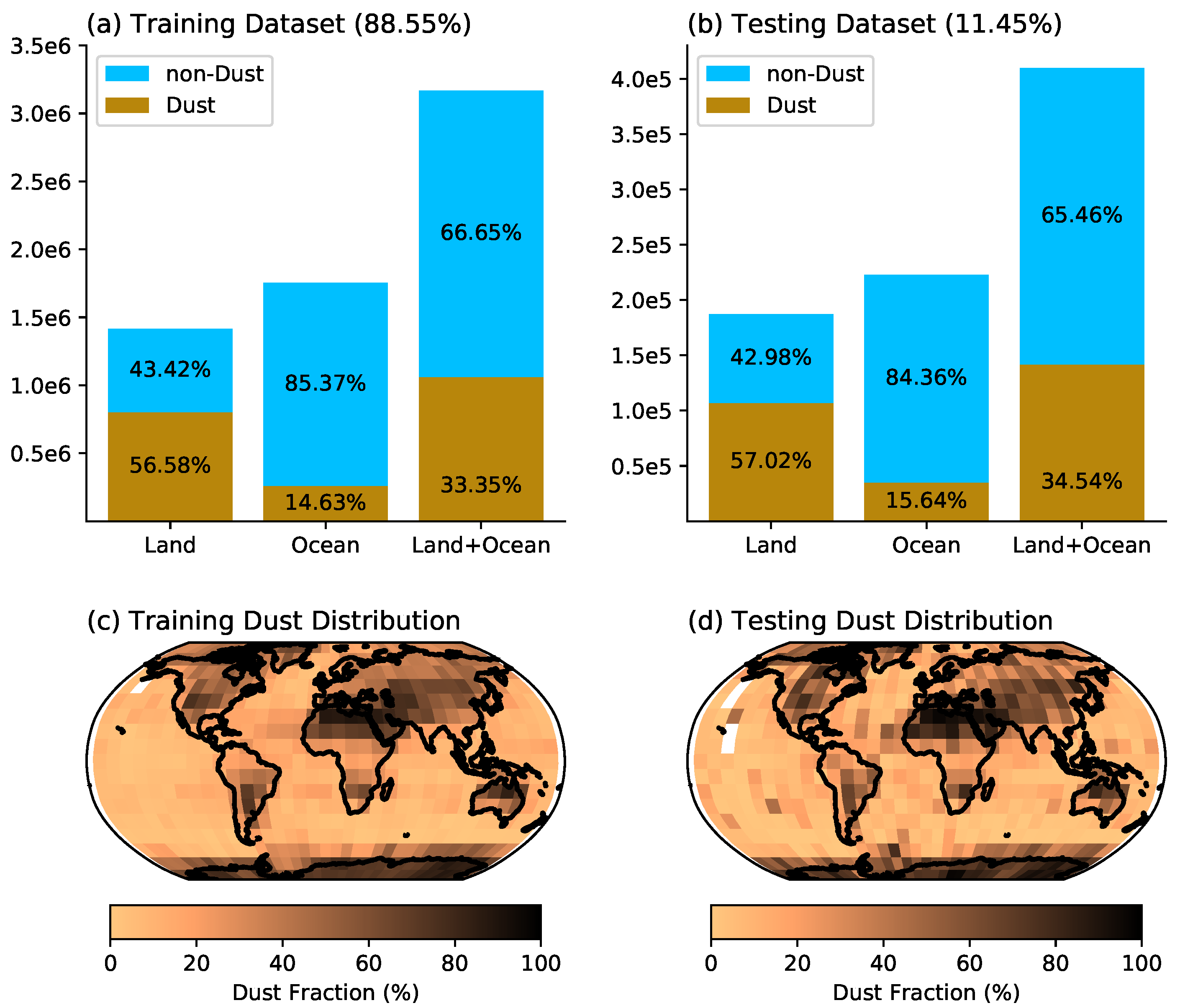
Statistics of training and testing data are depicted in Figure 2a,b. In the training data, dust pixels account for about 57% and 15% of all cloud-free pixels over land and ocean, respectively, which is expected because dust aerosols all originate in land and are only transported over to the ocean. Evidently, the ratios of dust to cloud-free pixels in the testing data (Figure 2b) are nearly identical to those in the testing data. Figure 2c,d show the global dust frequencies derived based on the training and testing data, respectively. The dust frequency is defined as the ratio of dusty pixels to the total cloud-free pixels within a 5 × 5 latitude-longitude grid. Over land, high dust frequencies are observed in those well-known dust laden regions, such as Sahara, central Asian, and Australia. A relatively high dust frequency is also observed in the tropical north Atlantic region in the training data (Figure 2c), which is expected because this is the outflow region of Sahara dust. On the other hand, some elevated dust frequency (>40%) is also observed over the Southern Ocean and the Antarctica continent. Although the dust from the Patagonian and Australian deserts can be transported to Southern Ocean, these transported dust events are likely to be intermittent and relatively rare in comparison with the dust events in the tropical north Atlantic. Therefore, the high dust frequency in these regions are likely to be the retrieval artifacts of CALIOP. The dust frequency map derived based on the testing data in Figure 2d is in overall good agreement with that based on the training data in Figure 2c, although it is noisier due to the small sampling rate.
Overall, two points are evident from Figure 2: First, the statistics and geographical distributions of the training and testing data are almost identical, which means there are no sampling bias generated by our method of splitting the data. Second, even though the CALIOP operational retrieval is considered as the state-of-the-art method to detect dust, it still faces some challenges. Inevitably, our algorithms that are trained based on CALIOP retrievals will also face these challenges as explained in Section 4.

2.3. Physics-Based Model (PHYS) from NOAA for Off-Track Comparison

It must be noted that, although our ML methods are trained and tested using collocated data on the CALIOP track, our ultimate goal is to apply the dust detection algorithm to the whole swath of VIIRS to achieve the best possible spatial sampling. One challenge facing us is how to evaluate the VIIRS dust detection results off the track of CALIOP when both the training and testing data, as described in the last section, are on track. To overcome this challenge, we introduce a physics-based VIIRS aerosol detection product (ADP) developed by a NOAA team [24,41]. It will be referred to as the PHYS model for short. This product identifies dust based on the dust spectral signatures, especially its strong absorption at ultraviolet (UV) and blue channels and its thermal signals. The product flags out smoke and dust over global cloud free and snow/ice free surfaces at 0.75 km spatial resolution at nadir view. Absorbing aerosol index (AAI) and Dust Smoke Discrimination Index (DSDI) are generated using the VIIRS M1 (0.415 µm), M2 (0.445 µm), and M11 (2.25 µm) bands following
A A I = 100 [ l o g 10 ( R M 1 / R M 2 ) l o g 1 0 ( R M 1 / R M 2 ) ]
D S D I = 10 [ l o g 10 ( R M 1 / R M 11 ) ]
where R is the observed top of atmosphere (TOA) reflectance and R′ is the reflectance from Rayleigh scattering. Using empirical thresholds, predefined thresholds that are suitable over general conditions are used to identify dust for each VIIRS pixel. The estimated accuracy for dust detection based on this physics-based ADP is 80% over land and over ocean. In addition, the detection limit of the VIIRS ADP product is set as for only smoke/dust events with AOD > 0.2, by considering the inability to separate aerosol type for AOD < 0.2 and threshold development is based on events with AOD > 0.2 [24,41]. It should be noted that the comparison of our ML based methods and the this PHYS model can be only considered as an evaluation rather than a validation because all the detection methods are designed based on different motivations for different purposes and they all have some inherent advantages and limitations.
In summary, we will train our ML based VIIRS dust detection methods based on the collocated on-track CALIOP data. Then, we will validate the methods using the on-track testing data. Finally, we will apply our methods to the whole VIIRS swath (i.e., off-track) and compare the results with NOAA’s PHYS model both on and off the CALIOP track.

3. ML Model Development

As explained in the Introduction, one objective of this study is to test and compare different ML methods for dust detection. More specifically, five different ML based methods are developed and their performances on dust detection are compared. These methods include logistic regression (LR), K-nearest neighbors (KNN), random forest (RF), feed forward neural network (FFNN), and convolutional neural network (CNN). Because they are commonly used methods, we only provide a brief introduction of each method here.

3.1. Logistic Regression (LR)

Logistic regression (LR) is a classification model that uses a logistic function, which converts the multivariate predictor variables into the output between 0 (clear sky) and 1 (dust). The main advantage of using LR is that the model is relatively easy to interpret in a physical sense due to its simple nature [42]. LR has been utilized in satellite image classification, such as forest classification [43] and tree defoliation [44] with successive performance. In this study, LR with L2 regularization is applied.

3.2. K-Nearest Neighbors (KNN)

As a non-parametric method, K-nearest neighbors (KNN) methods classify the input features into two or more classes by assigning the input features to the class that is most common among its K nearest neighbors. The main advantage of using KNN is that, since it considers the K nearest testing data, the classes do not have to be linearly separable. However, KNN could be very sensitive to imbalanced data and outliers. KNN has been used to estimate aboveground carbon from satellite imagery [45]. In this study, KNN with 10 nearest neighbors, with Euclidean distance weights selected as hyper-parameters, which are selected by grid search algorithm.

3.3. Random Forests (RF)

Random forests (RF) are an ensemble learning technique that performs classification or regression by building a structure of multiple decision trees. The performance of RF is considered to be comparable with the best supervised learning algorithms. There are multiple advantages of using RF. (1) Since RF works with the subsets of the data, it could cope better with high dimensional data, known as the “curse of dimensionality”. (2) RF can provide a reliable feature importance estimate, which could be used to reduce the dimension of the predictor variable [46]. RF with 100 max depths and 500 estimators is selected using the gridsearch algorithm.

3.4. Feedforward Neural Networks (FFNN)

Recently, artificial neural networks (ANN) have been widely used in remote sensing data. The fundamental structure of ANN consists of input layer, hidden layer(s), and output layer. There are variations of this structure for different objectives, such as recurrent neural networks, long short-term memory network, generative adversarial network, etc. The biggest advantage of using ANN is that is is able to learn on nonlinear and complex relationships. Furthermore, ANN does not require any restrictions on the input variables, such as multicollinearity, and distribution of predictor variables [47]. Here, we implement one of the most basic structures of ANN, a feedforward neural networks (FFNN). FFNN is a type of ANN with the connection between the nodes does not form a cycle or a loop, and only structured with input layer, hidden layer, and output layer. In this study, FFNN with three hidden layers is used. Batch size is set to be 256, with 2000 epochs. Batch size is selected with a gridsearch algorithm. Five different structures with different number and size of hidden layer were tested, and the best performing structure was selected. Although tested structures did not show significant difference in performance, it should be noted that, with more detailed tuning, FFNN has a room to improve.

3.5. Convolutional Neural Networks (CNN)

Convolutional neural networks (CNN) is another variation of ANN, most applied to visual imagery analysis [48]. The main advantage of using CNN is that CNN is able to capture the spatial dependencies in an image by applying filters. Furthermore, CNN extracts and reduces images without removing critical features. CNN has four different types of layers, input layer, convolution layer, pooling layer, and fully connected layer, respectively. In the input layer, CNN takes an input variable as an image, with a shape of image width × image height × channels. In this study, this corresponds to surrounding data width (5) × surrounding data height (5) × predictor variables (23). The convolution layer extracts the high-importance features from the image with a spatial filer, which is decided to be a 3 × 3 × 1 filter in this study. The pooling layer extracts the dominant features from the convolved data. In this study, max pooling is used to return the maximum value from the image covered by the filter. Finally, the model goes through a fully connected layer to make a decision. CNN has been applied to various problems in satellite imagery such as determining land type classification [49] and cloud classification [50]. CNN with one convolution layer with 2 × 2 kernel size and ReLu activation function is used. After the convolution layer, we used two dense layers with ReLu activation function, and one dense layer with sigmoid function for classification. Batch size is set to be 512, with 2000 epochs. Batch size and the number of epochs are selected with a gridsearch algorithm. Five different structures with different number and size of hidden layer were tested, and the best performing structure was selected.

3.6. Input Data Selection

As mentioned in Section 2.2, both 0-D and 2D input data structures are tested for each of the model, except for the CNN because it takes only 2D image as an input. In addition to pixel selection, we will also test the impact of predictor variable selection. As aforementioned, the feature importance analysis of the RF method provides us with a useful estimate of the usefulness of each predictor variable in Table 2 for dust detection. Using this analysis, we are able to rank the feature importance of all 23 predictor variables and selected nine variables (highlighted in bold in Table 2) with feature importance higher than the mean value. These selected variables include 4 M-bands (M09, M10, M11, M12 and M16) and two solar-viewing angles (SZA and SAA), as well as two pieces of geolocation information (Lat and Lon). The selected M-bands are in either the shortwave infrared (i.e., M09 to M12) or thermal infrared (i.e., M16). These bands have also been used, either separately or in combinations, in the previous physics-based dust detection algorithms. However, it is interesting and somewhat surprising to see that not a single visible band (e.g., M05) is selected, even though visible bands are frequently used in the literature for dust detection [20,25]. The selection of two solar-viewing angles is, on the other hand, not surprising because all the selected M-bands are solar-reflective bands. In addition, as the occurrence of dust events is very dependent on the region, the selection of two pieces of geolocation information of Lat and Lon is not unexpected. In addition, we used permutation importance from FFNN to compare the importance of features with RF. The top nine features from FFNN and RF was mostly common, but, in FFNN, latitude and longitude were excluded form the top 9 features, but M08 and M04 were included.
Based on different combinations of pixel selection and predictor variable selection, we prepared four sets of input data structures, 0D-allvar (23 predictor variables), 0D-selectvar (9 predictor variables), 2D-allvar ( 5 × 5 × 23 predictor variables), and 2D-selectvar ( 5 × 5 × 9 predictor variables) for each of the cases. A comparison between the 0-D and 2D results would help us understand to what extent the pixels adjacent to the CALIOP track provides additional information for dust detection on the CALIOP track. A comparison between “allVar” and “selectVar” results will help us understand if the same level of accuracy can be achieved by using a reduced number of predictor variables.

4. Model Evaluation

4.1. On-Track Validation and Comparison of ML Based Models

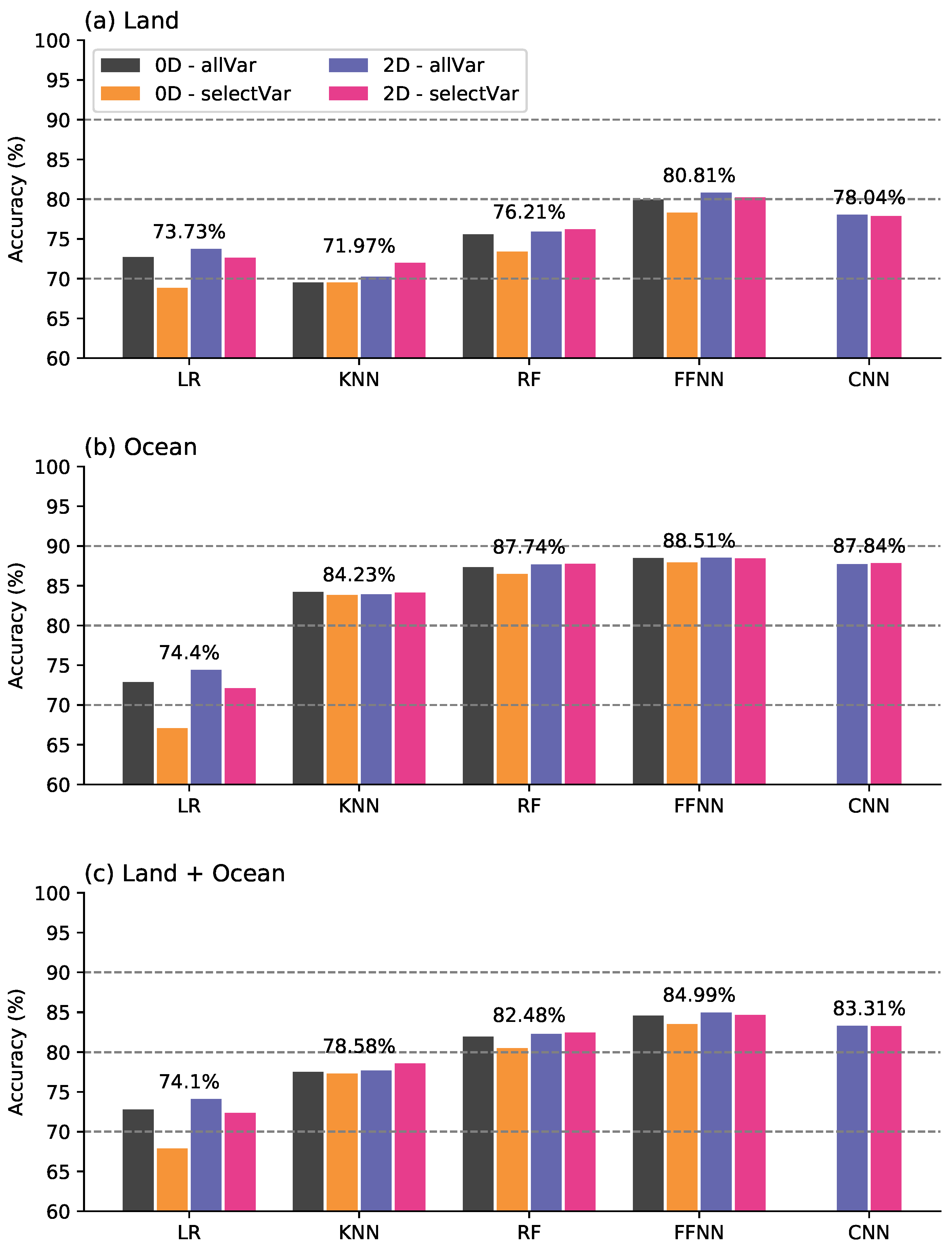
Five models (LR, KNN, RF, FFNN, and CNN) are trained with the training data based on the aforementioned four different sets of input data structures (0D-allvar, 0D-seectlvar, 2D-allvar, and 2D-selectvar). The training results are tested on the testing data (i.e., collocated CALIOP data). The overall accuracies of each model–variable combination after being aggregated over land, ocean, or the whole globe are compared in Figure 3.
A comparison between Figure 3a,b clearly reveals that all models perform better over the ocean compared to land. This is expected as the land surfaces make complicated lower boundary conditions compared to the ocean. Reflections by ocean surface are generally very small and thus the proportion of satellite received radiance that is from the atmospheric particles are larger. Another reason is that the radiative characteristics of the dust can be similar to those from semi-arid land surfaces, which makes it difficult to distinguish dust as the surface signals dominate the atmospheric signals. For both 0D and 2D cases, the allVar case tended to outperform or showed similar performance with selectVar in FFNN. This shows that the advantage of using ANN is that it can handle the large predictor variables itself without feature selection. This is similar to RF and CNN as well. FFNN outperformed CNN for about 1.7% accuracy. This shows that utilizing spatial characteristics of 5 × 5 VIIRS pixel window did not contribute to the model, compared to simply flattening the 5 × 5 window. Generally, CNN is best used for the image data, which usually consists hundreds or thousands of pixels. In that context, in future studies, a bigger window size could be used to improve the performance of CNN, since 5 × 5 window might be too small for CNN to perform efficiently.
For each method, the best performing feature cases are selected and compared for a statistical significance of performance. With a t-test, FFNN outperformed other methods at the 95% confidence level. CNN and RF did not show significant performance difference between them at the 95% confidence level; however, both outperformed KNN and LR. KNN also significantly outperformed LR.
As seen in the figure, the best model–predictor data combination is FFNN using the 2D-allvar, with overall accuracy of 84.99%. Thus, hereafter, we only analyze results from FFNN with a 2D-allvar predictor variable.
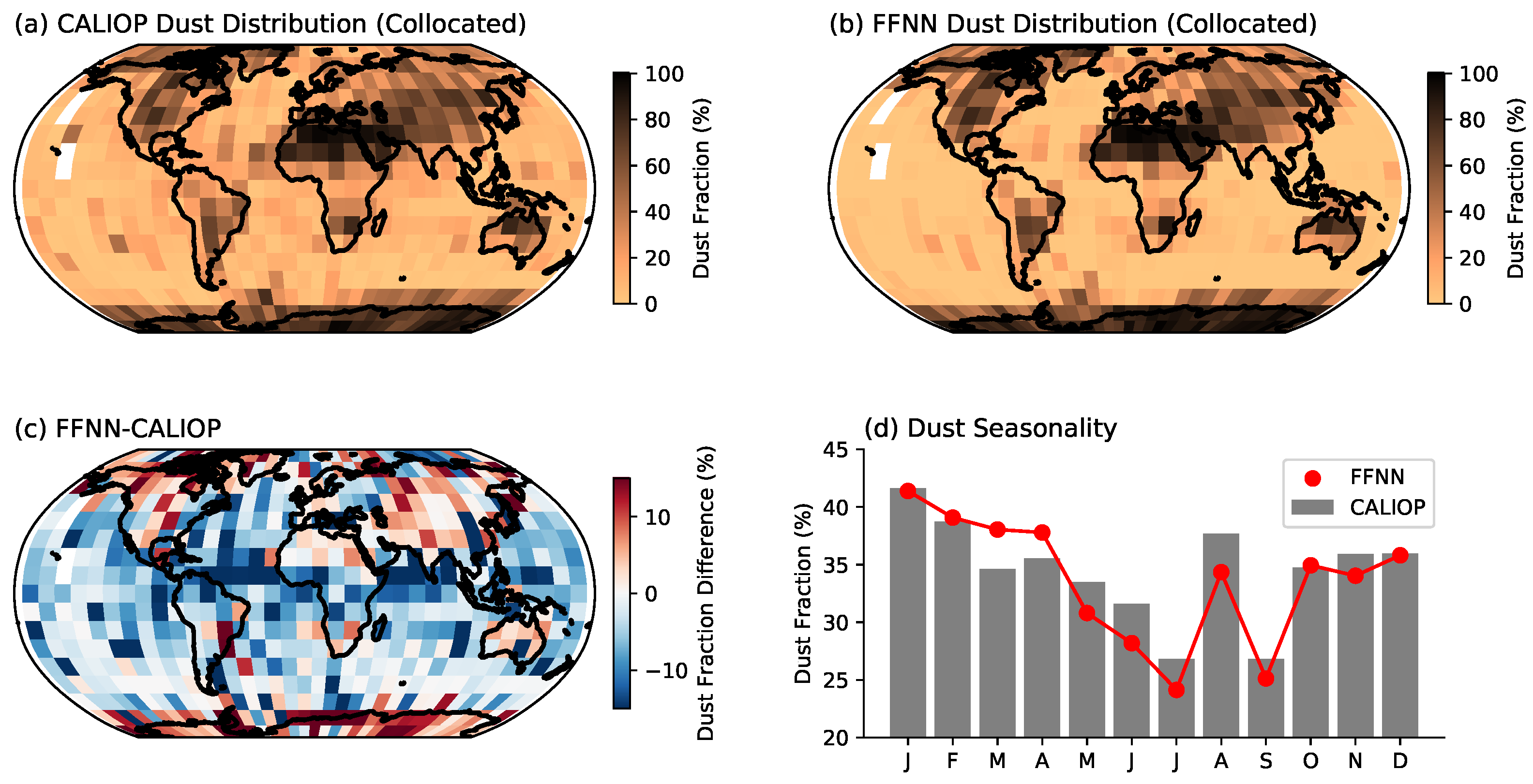
Figure 4 shows the global map of dust fraction derived from CALIOP (Figure 4a) and the collocated on-track VIIRS observations using the FFNN method (Figure 4b). As expected, FFNN is fairly good at resembling the spatial pattern of dust in CALIOP. CALIOP and FFNN present a 30% to 50% dust occurring fraction in central Asia, North America, Australia, South America, and at the tip of South Africa, which are the regions that are known as dust emission sources. However, CALIOP reports almost a 100% dust fraction in the Antarctic and adjacent Southern Ocean. As explained in Section 2, this is mostly misidentification due to retrieval artifacts. Inevitably, the FFNN method inherited this flaw from CALIOP and also reports high dust fractions in these regions. Nevertheless, it is evident from the figure that FFNN is able to closely reproduce the dust fraction map from CALIOP, with up to a 15% difference in dust distribution (Figure 4c), depending on the location. When averaged over the globe, as shown in Figure 4d, the FFNN-based VIIRS dust detection is able to reproduce the seasonality of dust observed by CALIOP, attesting to the usefulness of the detection for scientific studies.

4.2. On-Track Comparison of FFNN with the CALIOP and PHYS Model

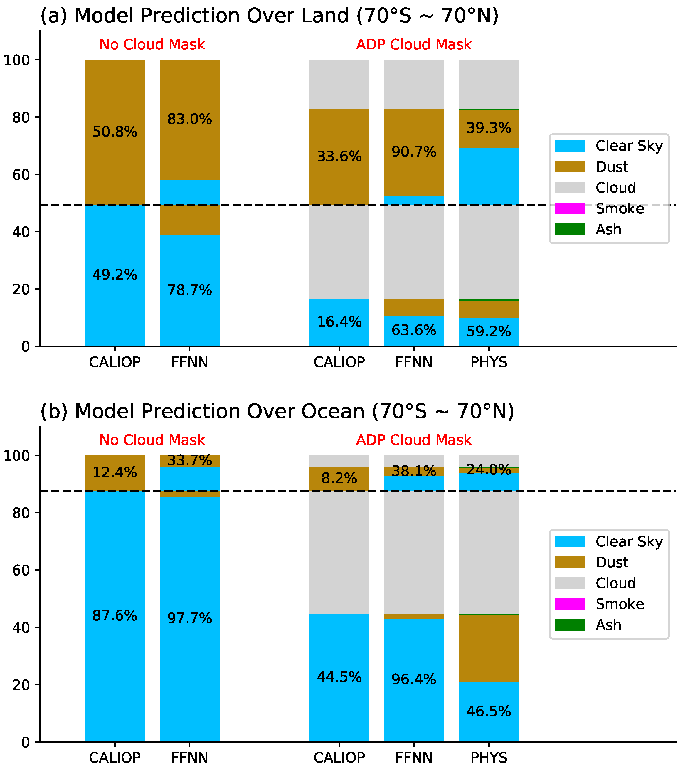
To further understand the differences between CALIOP, FFNN, and PHYS, we compared the dust detection from these three products on a pixel-to-pixel basis for the entire testing dataset on the CALIOP track excluding latitudes that are higher than 70 (Figure 5). For CALIOP and FFNN comparison, we used a CALIOP cloud mask to screen out cloudy pixels. Over land, CALIOP reports an average dust fraction of 51%, which is much higher compared to only 12% over ocean. As explained in Section 2, this is mainly because dust aerosols originate in land and only part of these dust plumes transport over the ocean. The larger portion of over land dust frequency is also partly due to the fact that a dust conservative screening method is used to identify dust plume. In other words, the definition of “dusty” in this study requires only one layer of dust to be detected by CALIOP through the entire atmospheric column. Finally, although really rare in the mid-to-high latitude region, it is also possible that CALIOP could misidentify cirrus clouds as dust if the clouds are too low in altitude.
Nevertheless, using CALIOP as the standards, FFNN shows a higher accuracy of prediction dust over both land and ocean. Overland FFNN true positive rate is 83% and false positive rate is 21%. The false positive rate is much lower than the true positive rate, which means that FFNN has the ability to separate surface signals with dust signals. It also could be that, over arid and semi-arid areas, where it is the hardest to detect dust, a high frequency of airborne dust occurs. Over the ocean, FFNN has a lower true positive rate of 33% with a very small false positive rate of 2%. The lower true positive rate indicates that FFNN has trouble separating dust from other aerosol types, which is also included in the clear sky categories. The very low false positive rate is partially due to the fact that, over the ocean, the occurrence of aerosol features might be much smaller than over land.
When comparing the PHYS model results with the CALIOP classification, there is a larger amount of cloud identified by PHYS when CALIOP products identify as dusty or clear skies (about one third over dusty conditions and about half when it is clear for both overland and ocean). The cloud prediction of PHYS is not generated in the ADP algorithm, but an upper stream cloud mask product [51]. Before the ADP algorithm is attempted, pixels are first filtered to ensure that the observing conditions are suitable for retrieval. Conditions such as clouds, cloud shadows, snow/ice coverage, or extreme viewing/illuminating geometries will be removed before retrieval. The PHYS model only predicts clear sky, dust, smoke, and ash for the remainder of the pixels. One of the known issues of a passive satellite aerosol retrieving algorithm is that optically thick aerosol plumes can be mistaken as clouds due to their similar spectral signals [52]. Another possibility that causes the disagreement in cloudiness between the two methods is the spatial resolution. Although this issue is mysterious, it is beyond the scope of this study. In addition, because Figure 5 only shows the results between 70 S and 70 N, another possibility of causing the disagreement, which is due to CALIOP falsely labeling low altitude ice clouds near polar region as dust, is mostly excluded from the statistics.
To remove the discrepancies due to cloud masking, we applied the ADP cloud mask to collocated CALIOP and FFNN results. After filtering by the ADP cloud mask, more than one third of CALIOP identified dust is removed over land and ocean. Under non-dust conditions, more than half of data are filtered over land and about half masked over the ocean. The remaining dusty percentage based on CALIOP is 33% over land and 8.2% over ocean. Over land, PHYS significantly under-predicts dust (39.3% from PHYS vs. 90.7% FFNN) with a similar false alarm rate as FFNN under non-dusty conditions. Over the ocean, the PHYS method shows a much higher false positive rate when compared with FFNN under non-dust conditions. As we mentioned before, CALIOP can be “too sensitive” to dust when very small dust components exist in the atmosphere or thin cirrus clouds present at low altitudes. However, only one condition leads to CALIOP incorrectly identifying dusty pixels to clouds, which is when the dust layer is very optically thick, which occurs mostly near the dust source region over land and very little in the transported dust layer over the ocean. Thus, the PHYS identified dusty pixels (more than half) under CALIOP non-dust conditions can be caused by mis-classifying other types of aerosols as dust. Over the ocean, PHYS has a slightly lower true positive rate when compared to FFNN. Excluding clouds, PHYS shows the true positive rate of 29% and 24% and the false positive rate of 40% and 53% for over land and ocean, respectively. The low true positive rate could be due to the different definitions applied between active sensor and passive sensor in terms of defining dust. For CALIOP, we consider an atmospheric column dusty if there is any dust observed in that vertical profile. FFNN follows the same definition since it is trained based on CALIOP data. This definition captures much more very low dust loading compared with what PHYS can do. The high false positive rate for PHYS, especially over the ocean, indicates that there is misclassification of other types of aerosols into dust by PHYS. Note again that our study excludes any cloudy scenes including thin cirrus identified by CALIOP. Under this circumstance, CALIOP has a reliable ability to separate dust from other aerosols under clear sky. Overall, FFNN can reproduce the CALIOP’s dust classification with a better accuracy than PHYS when following the CALIOP dust definition which includes conditions with very low dust loading.

5. Evaluation of FFNN-Based VIIRS Dust Detection off CALIOP Track

5.1. Entire VIIRS Granule Run for Days 75 and 224

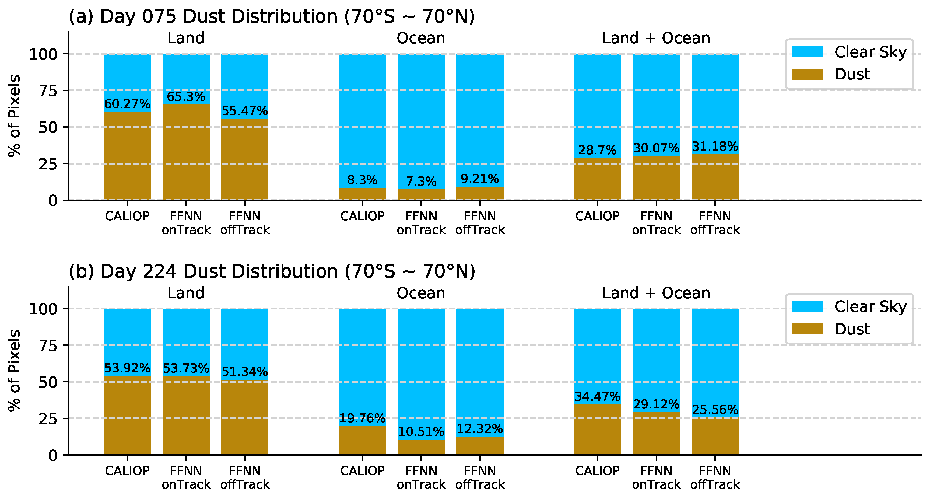
The previous analyses are all based on the CALIOP “truth” data, which is on its narrow track. To understand the ability of FFNN dust detection off the CALIOP track, we selected two days from the test days (day 075, which is March 16 and day 224, which is August 12). The same cloud mask that applied to the ADP product is used for masking the off-track VIIRS granule before feeding into FFNN to preserve clear-sky assumption. Figure 6 shows the dust distribution of CALIOP (collocated on track), FFNN (collocated on track), and FFNN (off-track) for days 075 and 224.
As seen in the figure, on-track and off-track FFNN dust detection accuracies mostly have a 10% difference, which is comparable to the difference between FFNN and CALIOP on the CALIOP track (see Figure 4c). This is very encouraging because it indicates that, although FFNN method is trained on the CALIOP track, it can be applicable for off-track pixels and maintains a similar accuracy. Difference in dust proportion is about 2% and 4% for both days. Since the coverage of collocated track and entire granule are different, we cannot expect the dust distribution to be the same for on-track and off-track. However, we also cannot expect the distribution to be very different because collocated track is a subset of the entire VIIRS granule, and it is fairly well distributed over the globe. In that context, 4% difference in the dust distribution is reasonable to assume that the result of FFNN model is consistent in both on and off-track.
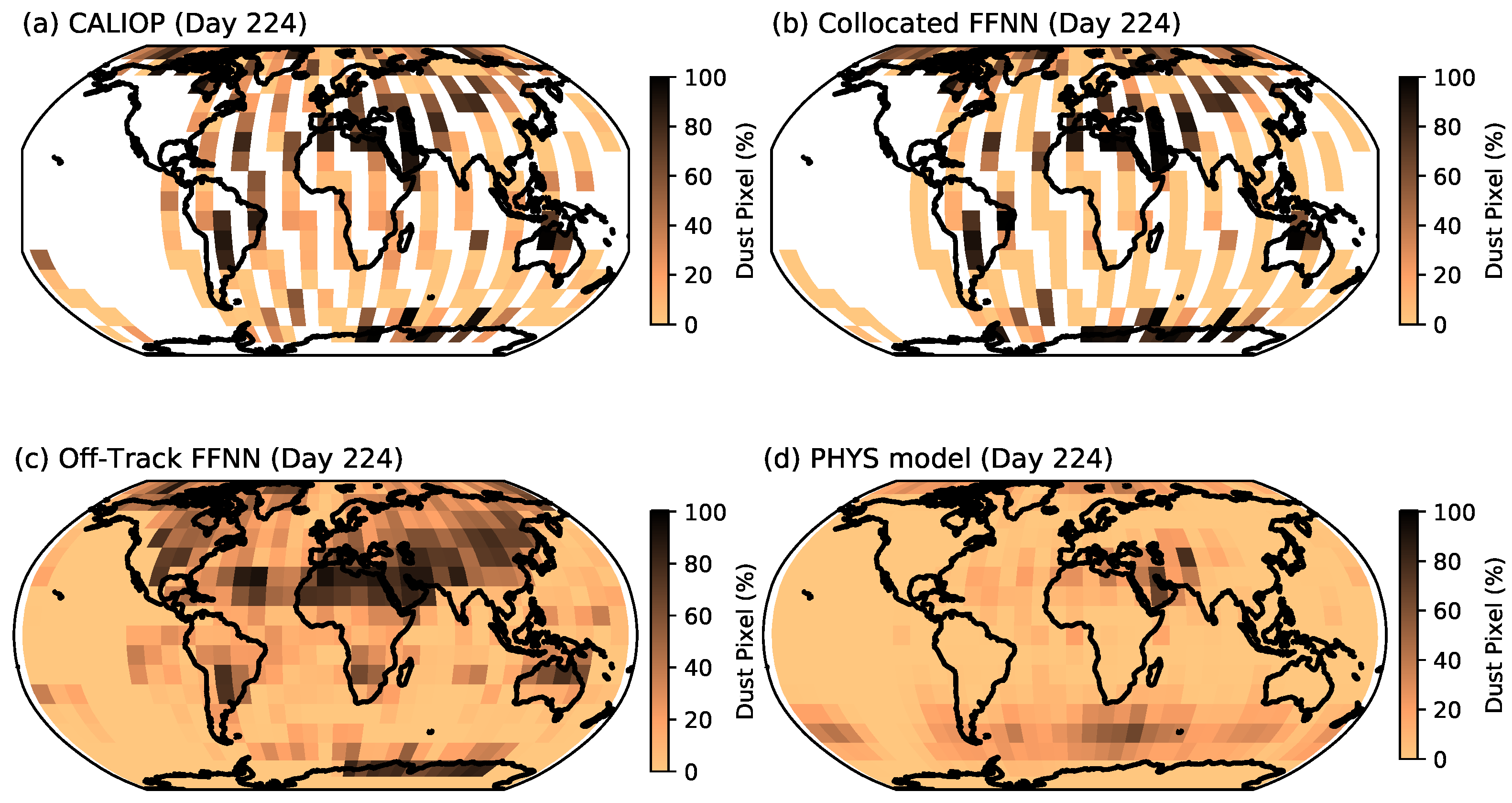
Figure 7 and Figure 8 show the dust occurrence frequency distribution of CALIOP product, on-track FFNN, off-track FFNN, and PHYS for day 075 (Figure 7) and day 224 (Figure 8). For day 075 (Figure 7), CALIOP and on-track FFNN shows a similar pattern of dust distribution, except for Antarctica, where FFNN overestimates dust frequency. Off-track FFNN also shows similar distribution with CALIOP in terms of both spatial distribution and occurrence of dust. Off-track FFNN also expands the small dust frequency over the ocean between south Africa and South America shown in an on-track CALIOP map. The visual inspection of RGB images of this region shows that transported dust exists and FFNN captures this feature. In on-track FFNN, there is couple elevated dust frequency pixels shown over the ocean west of Australia. These features are not shown in an on-track CALIOP map and is much reduced in off-track FFNN results. This indicates that the model may capture the feature better with more spatial coherence data. PHYS shows dust occurrence at similar geolocations with much smaller magnitude, which is consistent with our previous analyses. It is encouraging that none of the off-track results from FFNN and PHYS show any dust occurring over North and South America, as the CALIOP map indicates that there are no dust activities over these regions. Day 224 (Figure 8) shows a similar attribute to day 075 that both on- and off-track FFNN reproduce what CALIOP observes well at most of the region with one exception over North America, where CALIOP shows a small amount of dust occurrence over eastern North America, but off-track FFNN flags a lot more over this region. Another interesting observation is that both on-track maps show isolated high dust frequency in the middle of the Atlantic, where off-track FFNN shows the transport of dust plume from North Africa to this region. PHYS again captured a smaller amount of the significant dust activities that are identified by CALIOP. It barely shows the North Africa dust event with a very small magnitude, but yet we can still see that there is trace of dust plume from North Africa to the mid-Atlantic ocean. The PHYS also does not pick up the dust occurrence over South America, which is again visually identified using RGB images. It is worth mentioning that, over Asia, March is the active dust season and August is relatively calmer. We can see the magnitude differences over Asia between off-track FFNN results from these two days.

5.2. Off-Track Case Studies

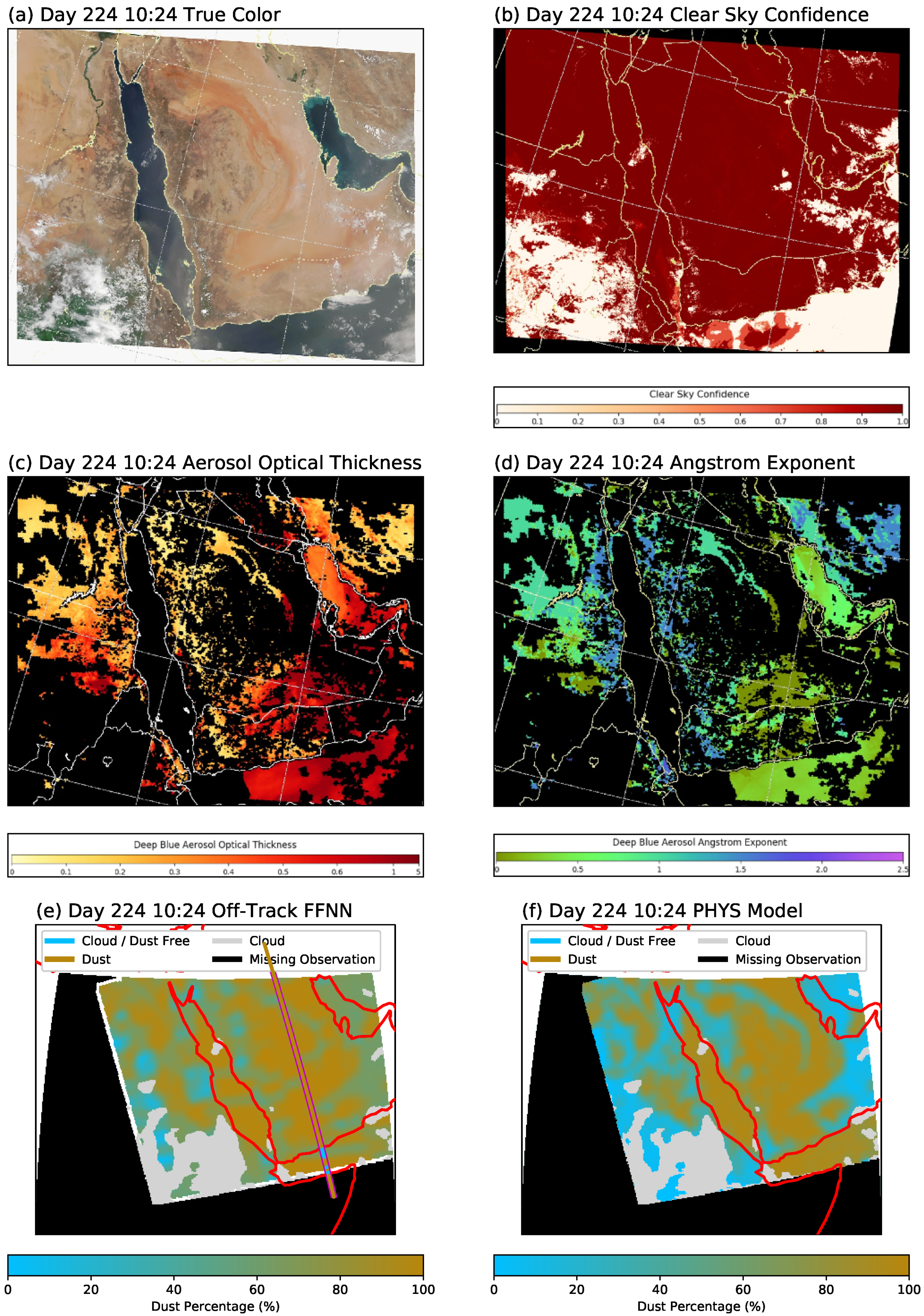
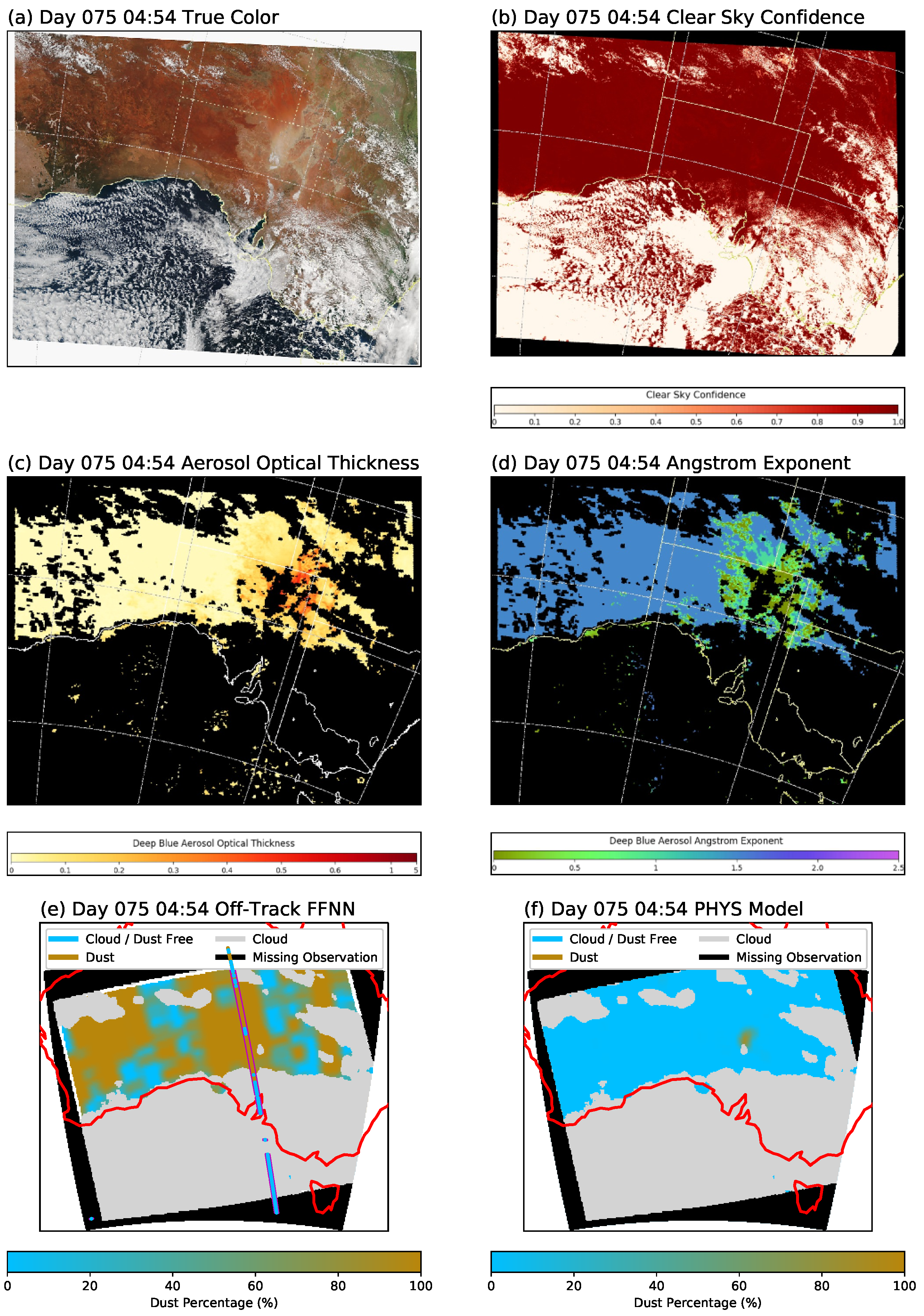
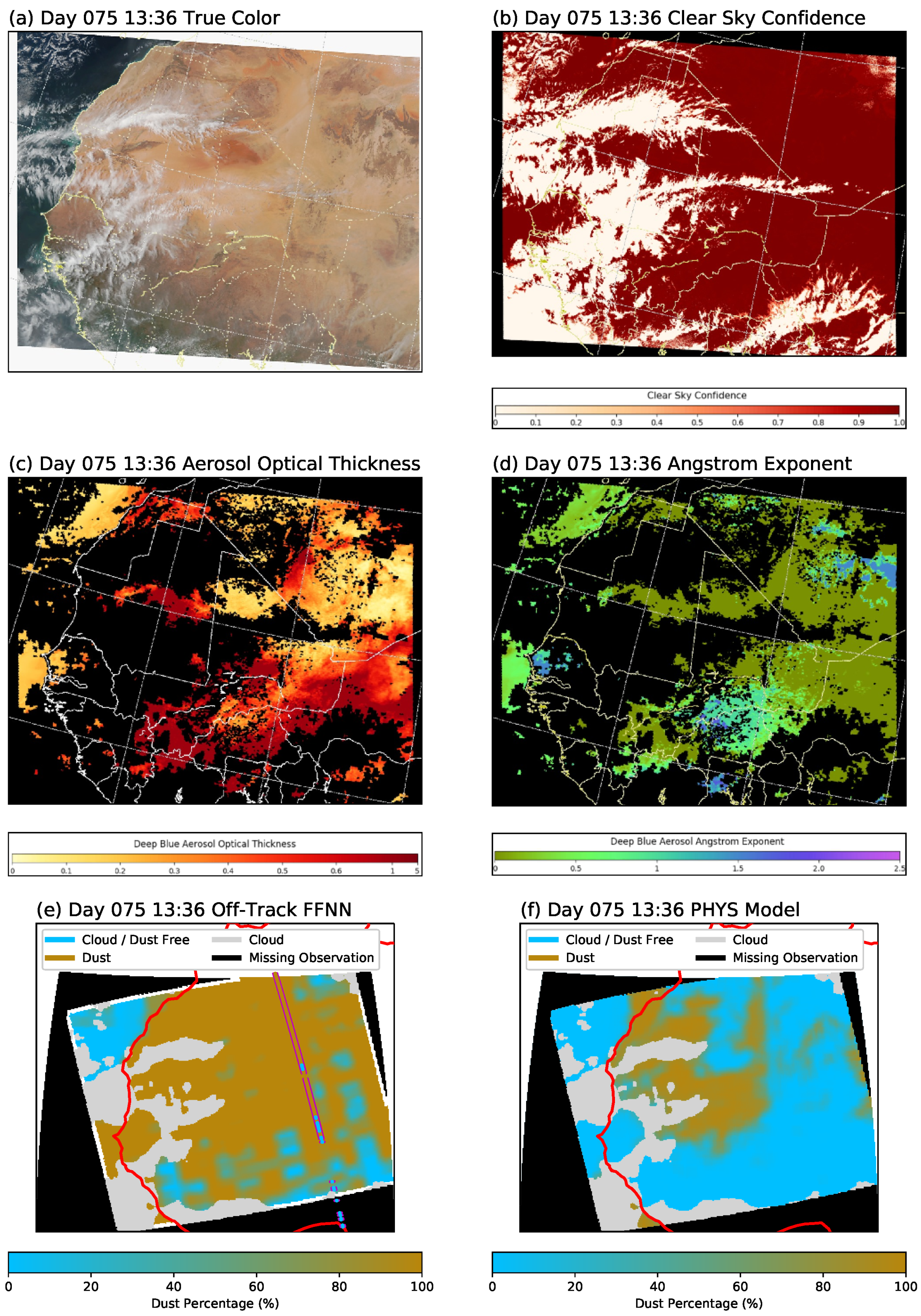
For the selected two days, subsets of granules are selected for both off-track FFNN and PHYS to compare with images from Wisconsin’s VIIRS quicklook, including RGB, AOD, and Angström Exponent parameter (https://sips.ssec.wisc.edu/#/). The Angström Exponent is a retrieved parameter to show the size of the retrieved aerosol. It shows how coarse the particle is within the aerosol plume that can best match the the observed radiance. The larger the value is, the smaller the particle size is. Generally, we consider less than 0.4 of the Angström Exponent to be dust. Because of the lacking of ground truth (CALIOP) for the off-track data, we use the RGB images, the magnitude of AOD, which shows the amount of aerosol loading, along with the Angström Exponent, which indicates dust or not to compare with off-track FFNN and PHYS results. Among a few cases, we select three different cases that show the characteristics of FFNN and PHYS.
Figure 9 shows a case over the Arabian peninsular on day 224 where FFNN and PHYS agree very well with each other in terms dust detection. The large value of AOD in Figure 9e suggests this case is a high dust loading case. Figure 9e also shows the CALIOP track and its dust product that are residing in this target region (see solid green and black line in panel e). As it can be seen in the figure, FFNN agrees very well with the CALIOP product on the CALIOP track, and predicts a high dust loading event in this region. PHYS also captures the similar pattern of dust, although the overall magnitude of dust loading is less significant compared to FFNN.
Figure 10 shows a case in Southern Australia on day 075, where the FFNN detects significant dust loading (Figure 10e) and PHYS detects almost none (Figure 10f). As seen from Figure 10c, the aerosol optical thickness in this case is quite small, mostly around 0.1. This thin layer of dust is not captured in PHYS, but it is captured both by CALIOP, albeit on its track only, and by FFNN both on-track and off-track. This is also expected from Figure 7 and Figure 8, where CALIOP and FFNN predicted a high frequency of dust over Australia, which is not seen in PHYS. Since CALIOP also captures dust in this regions, as shown in Figure 10e, the difference is probably due to the different definitions of dust event applied to CALIOP and PHYS, where CALIOP is more sensitive to a small amount of dust layers. However, it is debatable if this should be considered as a dust event, given the small amount of dust loading.
Finally, Figure 11 shows a case in the Sahara region on c, where the FFNN detects substantially more dust than the PHYS model. As seen from Figure 11b,c, the AOD in this case is quite high and the Angstrom exponent is small, indicating this to be a high dust loading case. The same as the previous two cases, the FFNN agrees very well with the CALIOP on the CALIOP track (Figure 11e). It also detects large areas of dust in this granule, for example over the eastern part of the granule where the AOD is high and Angstrom exponent is small. In comparison, the PHYS method does not label the aerosols in this region as dust. There could be multiple reasons for these differences such as the strong surface signal overpowering the atmospheric dust signal. An important one could be that all 16 M-bands of VIIRS are used in the FFNN method, whereas only 3 M-bands are used in the PHYS model.

6. Conclusions and Outlook

In this study, several ML based algorithms, namely, LR, KNN, RF, FFNN, and CNN, are tested for detecting the occurrence of dust aerosols from daytime VIIRS satellite images. These algorithms are trained based on one year (2014) of collocated state-of-the-art CALIOP dust detection products. Based on different combinations of pixel and predictor variable selections, four sets of input data are constructed for the training (i.e., 0D-AllVar, 0D-SelectVar, 2D-AllVar, 2D-SelectVar). A validation based on the testing data shows that the FFNN trained with the 2D-allVar input data is the best performing model, with a 84.99% overall accuracy on the CALIOP track. The FFNN model was then tested for the entire VIIRS granule, which covers more regions than CALIOP-VIIRS collocated track spatially. Off-track FFNN dust distribution agrees reasonably well with collocated track FFNN dust distribution, which indicates that there was no systematic bias between on and off track model application. In addition, off-track dust distribution showed a similar distribution with on-track CALIOP predictions, which warrants that the FFNN can be used to reproduce CALIOP results outside the CALIOP track. Comparisons are also made between the FFNN method with a physically-based dust detection algorithm both on and off the CALIOP track. The FFNN method agrees better with the CALIOP than the PHYS model on the CALIOP track, which is expected because FFNN is trained based on CALIOP observations. When applied to all of the VIIRS granules, the FFNN detects significantly more dust than the PHYS model. Case studies suggest that the difference may be coming from a number of different factors, such as the different definitions of the dust event and the use of different numbers of VIIRS observations in the two algorithms.
As far as we know, this is the first attempt to use an ML based algorithm trained with the collocated CALIOP products for global dust detection from satellite images. The results suggest that, even though the ML algorithms are only trained on the narrow track of CALIOP, they can be applied to the whole VIIRS granule and retrieve statistically similar dust frequency. This is very encouraging and meaningful for a couple of reasons. First of all, this study, along with many recent ones (e.g., [34]), demonstrates the great potential of ML methods for satellite based aerosol and cloud retrievals. Second, our study also demonstrates that, even through the active sensors like CALIOP have an extremely small spatial sampling rate, their observations and retrievals provide unique information on aerosol that are highly useful for training the ML methods. However, a close collocation between the active and passive sensors are needed, which is an important factor to be considered in the planning of next-generation NASA satellite missions.
Despite the encouraging results, our study has several important limitations. First, the abnormally high frequency of dust in the Antarctic and some remote ocean regions indicate that our ML methods inherited some misidentification problems from the CALIOP retrieval. The problems of the operational CALIOP aerosol retrievals are beyond the scope this study. In future research, this issue could be alleviated by using additional constraints, such as the AOD value, for dust detection when constructing the training data. Second, because we excluded cloudy pixels from this study, our algorithms can only detect dust in cloud-free conditions and require a reliable cloud masking algorithm to screen out the cloudy pixels first. Theoretically, it is possible to train ML algorithms to identify both clouds and dust at the same time if there can be enough high-quality training data. However, this would be much more challenging and will be explored in future research. Third, our algorithms can be used only during the daytime. In future research, the ML algorithms can be trained only using the thermal infrared bands of VIIRS and as such they will be able to detect dust during both the daytime and nighttime. Finally, the off-track results need to be further evaluated in future research based on more reliable independent dust detection products, for example, collocated ground-based AeroNET and/or lidar observations.
In this study, we have achieved our main objective, i.e., exploring the feasibility of using the ML methods trained on the CALIOP track for off-track dust detection. The results are very encouraging and also inspiring. Many questions are raised during this study that warrant further investigations in the future. Here are a few examples. The RF method ranked three shortwave infrared bands and one thermal radiation bands as the most important bands in terms of information content for dust detection. What are the underlying physics for this ranking? The very similar results based on the 0-D and 2D input data structures seem to suggest that the adjacent pixels provide little additional information for dust detection. Is this due to the nature of dust plume (i.e., a lack of spatial structure) or a result of inadequate spatial window (i.e., larger or smaller than 5 × 5 pixels for 2D)?

Author Contributions

Conceptualization, J.L., Y.R.S., and C.C.; methodology, J.L. and Y.R.S.; software, J.L.; validation, J.L., Y.R.S., and P.C.; formal analysis, J.L. and Y.R.S.; investigation, J.L. and Y.R.S.; resources, J.W. and Z.Z.; writing—original draft preparation, J.L., Y.R.S., and Z.Z.; writing—review and editing, J.L., Y.R.S., and Z.Z.; visualization, J.L., Y.R.S.; supervision, Z.Z.; project administration, A.G. and Z.Z.; funding acquisition, J.W. and Z.Z. All authors have read and agreed to the published version of the manuscript.

Funding

This research is supported grants from NASA’s CCST program (Grant No. 80NSSC20K0130) managed by David Considine and the NSF Cybertraining program (Grant No. OAC–1730250). The computational resources are provided by the UMBC High Performance Computing Facility (HPCF) which was supported by the U.S. National Science Foundation through the MRI program (Grant Nos. CNS–0821258, CNS–1228778, and OAC–1726023) and the SCREMS program (Grant No. DMS– 0821311), with additional substantial support from the University of Maryland, Baltimore County (UMBC). See hpcf.umbc.edu for more information on HPCF and the projects using its resources.

Data Availability Statement

All data used in this study including the Machine Learning model outputs and PHYS retrievals can be distributed upon request.

Acknowledgments

We thank Lorraine Remer, Hongbin Yu, Shobha Kondragunta, Robert Levy, and Yaping Zhou for inspiring discussions and suggestive comments.

Conflicts of Interest

The authors declare no conflict of interest.

References

  1. Sugden, D.E.; McCulloch, R.D.; Bory, A.J.M.; Hein, A.S. Influence of Patagonian glaciers on Antarctic dust deposition during the last glacial period. Nat. Geosci. 2009, 2, 281–285. [Google Scholar] [CrossRef] [Green Version]
  2. Uno, I.; Eguchi, K.; Yumimoto, K.; Takemura, T.; Shimizu, A.; Uematsu, M.; Liu, Z.; Wang, Z.; Hara, Y.; Sugimoto, N. Asian dust transported one full circuit around the globe. Nat. Geosci. 2009, 2, 557–560. [Google Scholar] [CrossRef]
  3. Prospero, J.M. Long-range transport of mineral dust in the global atmosphere: Impact of African dust on the environment of the southeastern United States. Proc. Natl. Acad. Sci. USA 1999, 96, 3396–3403. [Google Scholar] [CrossRef] [PubMed] [Green Version]
  4. Griffin, D.W.; Kellogg, C.A. Dust storms and their impact on ocean and human health: Dust in Earth’s atmosphere. EcoHealth 2004, 1, 284–295. [Google Scholar] [CrossRef]
  5. Thalib, L.; Al-Taiar, A. Dust storms and the risk of asthma admissions to hospitals in Kuwait. Sci. Total Environ. 2012, 433, 347–351. [Google Scholar] [CrossRef]
  6. Kahn, B.H.; Takahashi, H.; Stephens, G.L.; Yue, Q.; Delanoë, J.; Manipon, G.; Manning, E.; Heymsfield, A.J. Ice cloud microphysical trends observed by the Atmospheric Infrared Sounder. Atmos. Chem. Phys. 2018, 18, 10715–10739. [Google Scholar] [CrossRef] [Green Version]
  7. Torres, O.; Bhartia, P.K.; Herman, J.R.; Ahmad, Z.; Gleason, J. Derivation of aerosol properties from satellite measurements of backscattered ultraviolet radiation: Theoretical basis. J. Geophys. Res. Atmos. 1998, 103, 17099–17110. [Google Scholar] [CrossRef]
  8. Alpert, P.; Kishcha, P.; Shtivelman, A.; Krichak, S.O.; Joseph, J.H. Vertical distribution of Saharan dust based on 2.5-year model predictions. Atmos. Res. 2004, 70, 109–130. [Google Scholar] [CrossRef]
  9. Moorthy, K.K.; Babu, S.S.; Satheesh, S.K.; Srinivasan, J.; Dutt, C.B.S. Dust absorption over the “Great Indian Desert” inferred using ground-based and satellite remote sensing. J. Geophys. Res. Atmos. 2007, 112. [Google Scholar] [CrossRef] [Green Version]
  10. Evan, A.T.; Heidinger, A.K.; Pavolonis, M.J. Development of a new over-water Advanced Very High Resolution Radiometer dust detection algorithm. Int. J. Remote Sens. 2006, 27, 3903–3924. [Google Scholar] [CrossRef]
  11. Zhu, A.; Ramanathan, V.; Li, F.; Kim, D. Dust plumes over the Pacific, Indian, and Atlantic oceans: Climatology and radiative impact. J. Geophys. Res. Atmos. 2007, 112. [Google Scholar] [CrossRef]
  12. MacKinnon, D.J.; Chavez, P.S., Jr.; Fraser, R.S.; Niemeyer, T.C.; Gillette, D.A. Calibration of GOES-VISSR, visible-band satellite data and its application to the analysis of a dust storm at Owens Lake, California. Geomorphology 1996, 17, 229–248. [Google Scholar] [CrossRef]
  13. Torres, O.; Tanskanen, A.; Veihelmann, B.; Ahn, C.; Braak, R.; Bhartia, P.K.; Veefkind, P.; Levelt, P. Aerosols and surface UV products from Ozone Monitoring Instrument observations: An overview. J. Geophys. Res. Atmos. 2007, 112. [Google Scholar] [CrossRef] [Green Version]
  14. Shi, Y.; Zhang, J.; Reid, J.S.; Hyer, E.J.; Hsu, N.C. Critical evaluation of the MODIS Deep Blue aerosol optical depth product for data assimilation over North Africa. Atmos. Meas. Tech. 2013, 6, 949. [Google Scholar] [CrossRef] [Green Version]
  15. Zhao, X. Asian dust detection from the satellite observations of moderate resolution imaging spectroradiometer (MODIS). Aerosol Air Qual. Res. 2012, 12, 1073–1080. [Google Scholar] [CrossRef] [Green Version]
  16. Souri, A.H.; Vajedian, S. Dust storm detection using random forests and physical-based approaches over the Middle East. J. Earth Syst. Sci. 2015, 124, 1127–1141. [Google Scholar] [CrossRef] [Green Version]
  17. Cho, H.M.; Nasiri, S.L.; Yang, P.; Laszlo, I.; Zhao, X.T. Detection of optically thin mineral dust aerosol layers over the ocean using MODIS. J. Atmos. Ocean. Technol. 2013, 30, 896–916. [Google Scholar] [CrossRef]
  18. Kaufman, Y.J.; Karnieli, A.; Tanré, D. Detection of dust over deserts using satellite data in the solar wavelengths. IEEE Trans. Geosci. Remote Sens. 2000, 38, 525–531. [Google Scholar] [CrossRef] [Green Version]
  19. Legrand, M.; Desbois, M.; Vovor, K. Satellite detection of Saharan dust: Optimized imaging during nighttime. J. Clim. 1988, 1, 256–264. [Google Scholar] [CrossRef] [Green Version]
  20. Zhao, T.X.P.; Ackerman, S.; Guo, W. Dust and smoke detection for multi-channel imagers. Remote Sens. 2010, 2, 2347–2368. [Google Scholar] [CrossRef] [Green Version]
  21. Winker, D.M.; Pelon, J.; Coakley, J.A., Jr.; Ackerman, S.A.; Charlson, R.J.; Colarco, P.R.; Flamant, P.; Fu, Q.; Hoff, R.M.; Kittaka, C.; et al. The CALIPSO mission: A global 3D view of aerosols and clouds. Bull. Am. Meteorol. Soc. 2010, 91.9, 1211–1230. [Google Scholar] [CrossRef]
  22. Winker, D.M.; Vaughan, M.A.; Omar, A.; Hu, Y.; Powell, K.A. Overview of the CALIPSO Mission and CALIOP Data Processing Algorithms. J. Atmos. Ocean. Technol. 2009, 26, 2310–2323. [Google Scholar] [CrossRef]
  23. Peyridieu, S.; Chédin, A.; Tanré, D.; Capelle, V.; Pierangelo, C.; Lamquin, N.; Armante, R. Saharan dust infrared optical depth and altitude retrieved from AIRS: A focus over North Atlantic–comparison to MODIS and CALIPSO. Atmos. Chem. Phys. 2010, 10, 1953–1967. [Google Scholar] [CrossRef] [Green Version]
  24. Ciren, P.; Kondragunta, S. Dust aerosol index (DAI) algorithm for MODIS. J. Geophys. Res. Atmos. 2014, 119, 4770–4792. [Google Scholar] [CrossRef]
  25. Zhou, Y.; Levy, R.C.; Remer, L.A.; Mattoo, S.; Shi, Y.; Wang, C. Dust Aerosol Retrieval over the Oceans with the MODIS/VIIRS Dark Target algorithm. Part I: Dust Detection. Earth Space Sci. 2020, 7, e2020EA001221. [Google Scholar] [CrossRef]
  26. Shi, P.; Song, Q.; Patwardhan, J.; Zhang, Z.; Wang, J.; Gangopadhyay, A. A hybrid algorithm for mineral dust detection using satellite data. In Proceedings of the 15th International Conference on eScience (eScience), San Diego, CA, USA, 24–27 September 2019; pp. 39–46. [Google Scholar] [CrossRef]
  27. Boroughani, M.; Pourhashemi, S.; Hashemi, H.; Salehi, M.; Amirahmadi, A.; Asadi, M.A.Z.; Berndtsson, R. Application of remote sensing techniques and machine learning algorithms in dust source detection and dust source susceptibility mapping. Ecol. Inform. 2020, 56, 101059. [Google Scholar] [CrossRef]
  28. Hou, P.; Guo, P.; Wu, P.; Wang, J.; Gangopadhyay, A.; Zhang, Z. A Deep Learning Model for Detecting Dust in Earth’s Atmosphere from Satellite Remote Sensing Data. In Proceedings of the 2020 IEEE International Conference on Smart Computing (SMARTCOMP), Bologna, Italy, 14–17 September 2020; pp. 196–201. [Google Scholar] [CrossRef]
  29. Shi, L.; Zhang, J.; Zhang, D.; Igbawua, T.; Liu, Y. Developing a dust storm detection method combining Support Vector Machine and satellite data in typical dust regions of Asia. Adv. Space Res. 2020, 65, 1263–1278. [Google Scholar] [CrossRef]
  30. Rivas-Perea, P.; Rosiles, J.G.; Cota-Ruiz, J. Statistical and neural pattern recognition methods for dust aerosol detection. Int. J. Remote Sens. 2013, 34, 7648–7670. [Google Scholar] [CrossRef]
  31. Horváth, Á.; Seethala, C.; Deneke, H. View angle dependence of MODIS liquid water path retrievals in warm oceanic clouds. J. Geophys. Res. Atmos. 2014, 119, 8304–8328. [Google Scholar] [CrossRef] [Green Version]
  32. Maddux, B.C.; Ackerman, S.A.; Platnick, S. Viewing geometry dependencies in MODIS cloud products. J. Atmos. Ocean. Technol. 2010, 27, 1519–1528. [Google Scholar] [CrossRef]
  33. Cho, H.M.; Zhang, Z.; Meyer, K.; Lebsock, M.; Platnick, S.; Ackerman, A.S.; Di Girolamo, L.; Labonnote, L.C.; Cornet, C.; Riedi, J.; et al. Frequency and causes of failed MODIS cloud property retrievals for liquid phase clouds over global oceans. J. Geophys. Res. Atmos. 2015, 120, 4132–4154. [Google Scholar] [CrossRef] [PubMed]
  34. Wang, C.; Platnick, S.; Meyer, K.; Zhang, Z.; Zhou, Y. A machine-learning-based cloud detection and thermodynamic-phase classification algorithm using passive spectral observations. Atmos. Meas. Tech. 2020, 13, 2257–2277. [Google Scholar] [CrossRef]
  35. Liu, Z.; Vaughan, M.; Winker, D.; Kittaka, C.; Getzewich, B.; Kuehn, R.; Omar, A.; Powell, K.; Trepte, C.; Hostetler, C. The CALIPSOLidar Cloud and Aerosol Discrimination: Version 2 Algorithm and Initial Assessment of Performance. J. Atmos. Ocean. Technol. 2009, 26, 1198–1213. [Google Scholar] [CrossRef]
  36. Liu, Z.; Kar, J.; Zeng, S.; Tackett, J.; Vaughan, M.; Avery, M.; Pelon, J.; Getzewich, B.; Lee, K.P.; Magill, B.; et al. Discriminating between clouds and aerosols in the CALIOP version 4.1 data products. Atmos. Meas. Tech. 2019, 12, 703–734. [Google Scholar] [CrossRef] [Green Version]
  37. Kim, M.H.; Omar, A.H.; Tackett, J.L.; Vaughan, M.A.; Winker, D.M.; Trepte, C.R.; Hu, Y.; Liu, Z.; Poole, L.R.; Pitts, M.C.; et al. The CALIPSO version 4 automated aerosol classification and lidar ratio selection algorithm. Atmos. Meas. Tech. 2018, 11, 6107–6135. [Google Scholar] [CrossRef] [Green Version]
  38. Vaughan, M.A.; Powell, K.A.; Winker, D.M.; Hostetler, C.A.; Kuehn, R.E.; Hunt, W.H.; Getzewich, B.J.; Young, S.A.; Liu, Z.; McGill, J.M. Fully Automated Detection of Cloud and Aerosol Layers in the CALIPSO Lidar Measurements. J. Atmos. Ocean. Technol. 2009, 26, 2034–2050. [Google Scholar] [CrossRef]
  39. Holz, R.E.; Ackerman, S.A.; Nagle, F.W.; Frey, R.; Dutcher, S.; Kuehn, R.E. Global Moderate Resolution Imaging Spectroradiometer (MODIS) cloud detection and height evaluation using CALIOP. J. Geophys. Res. Atmos. 2008, 112. [Google Scholar] [CrossRef] [Green Version]
  40. Zhang, Z.; Meyer, K.; Yu, H.; Platnick, S.; Colarco, P.; Liu, Z.; Oreopoulos, L. Shortwave direct radiative effects of above-cloud aerosols over global oceans derived from 8 years of CALIOP and MODIS observations. Atmos. Chem. Phys. 2016, 16, 2877–2900. [Google Scholar] [CrossRef] [Green Version]
  41. Ciren, P.; Kondragunta, S. NOAA/NESDIS/STAR Algorithm Theoretical Basis Document: JPSS Aerosol Detection Product. Available online: https://www.star.nesdis.noaa.gov/smcd/spb/aq/AerosolWatch/docs/JPSS_VIIRS_EPS_ADP_ATBD_V1.3_20180606.pdf (accessed on 6 December 2020).
  42. Dreiseitl, S.; Ohno-Machado, L. Logistic regression and artificial neural network classification models: A methodology review. J. Biomed. Inform. 2002, 35, 352–359. [Google Scholar] [CrossRef] [Green Version]
  43. McRoberts, R.E. Satellite image-based maps: Scientific inference or pretty pictures? Remote Sens. Environ. 2011, 115, 715–724. [Google Scholar] [CrossRef]
  44. Fraser, R.H.; Latifovic, R. Mapping insect-induced tree defoliation and mortality using coarse spatial resolution satellite imagery. Int. J. Remote Sens. 2005, 26, 193–200. [Google Scholar] [CrossRef]
  45. Zhou, G.; Xu, X.; Du, H.; Ge, H.; Shi, Y.; Zhou, Y. Estimating aboveground carbon of Moso bamboo forests using the k nearest neighbors technique and satellite imagery. Photogramm. Eng. Remote Sens. 2011, 77, 1123–1131. [Google Scholar] [CrossRef]
  46. Pal, M. Random forest classifier for remote sensing classification. Int. J. Remote Sens. 2005, 26, 217–222. [Google Scholar] [CrossRef]
  47. Tu, J.V. Advantages and disadvantages of using artificial neural networks versus logistic regression for predicting medical outcomes. J. Clin. Epidemiol. 1996, 49, 1225–1231. [Google Scholar] [CrossRef]
  48. Krizhevsky, A.; Sutskever, I.; Hinton, G.E. Imagenet classification with deep convolutional neural networks. Adv. Neural Inf. Process. Syst. 2012, 1097–1105. [Google Scholar] [CrossRef]
  49. Zhong, Y.; Fei, F.; Liu, Y.; Zhao, B.; Jiao, H.; Zhang, L. SatCNN: Satellite image dataset classification using agile convolutional neural networks. Remote Sens. Lett. 2017, 8, 136–145. [Google Scholar] [CrossRef]
  50. Cai, K.; Wang, H. Cloud classification of satellite image based on convolutional neural networks. In Proceedings of the 2017 8th IEEE International Conference on Software Engineering and Service Science, Beijing, China, 24–26 November 2017; pp. 874–877. [Google Scholar] [CrossRef]
  51. Andrew, H.; Botambekov, D.; Walther, A. NOAA/NESDIS/STAR Algorithm Theoretical Basis Document: A Naïve Bayesian Cloud Mask Delivered to NOAA Enterprise. Available online: https://www.star.nesdis.noaa.gov/jpss/documents/ATBD/ATBD_EPS_Cloud_Mask_v1.2.pdf (accessed on 16 August 2016).
  52. Shi, Y.R.; Levy, R.C.; Eck, T.F.; Fisher, B.; Mattoo, S.; Remer, L.A.; Slutsker, I.; Zhang, J. Characterizing the 2015 Indonesia fire event using modified MODIS aerosol retrievals. Atmos. Chem. Phys. 2019, 19, 259. [Google Scholar] [CrossRef] [Green Version]
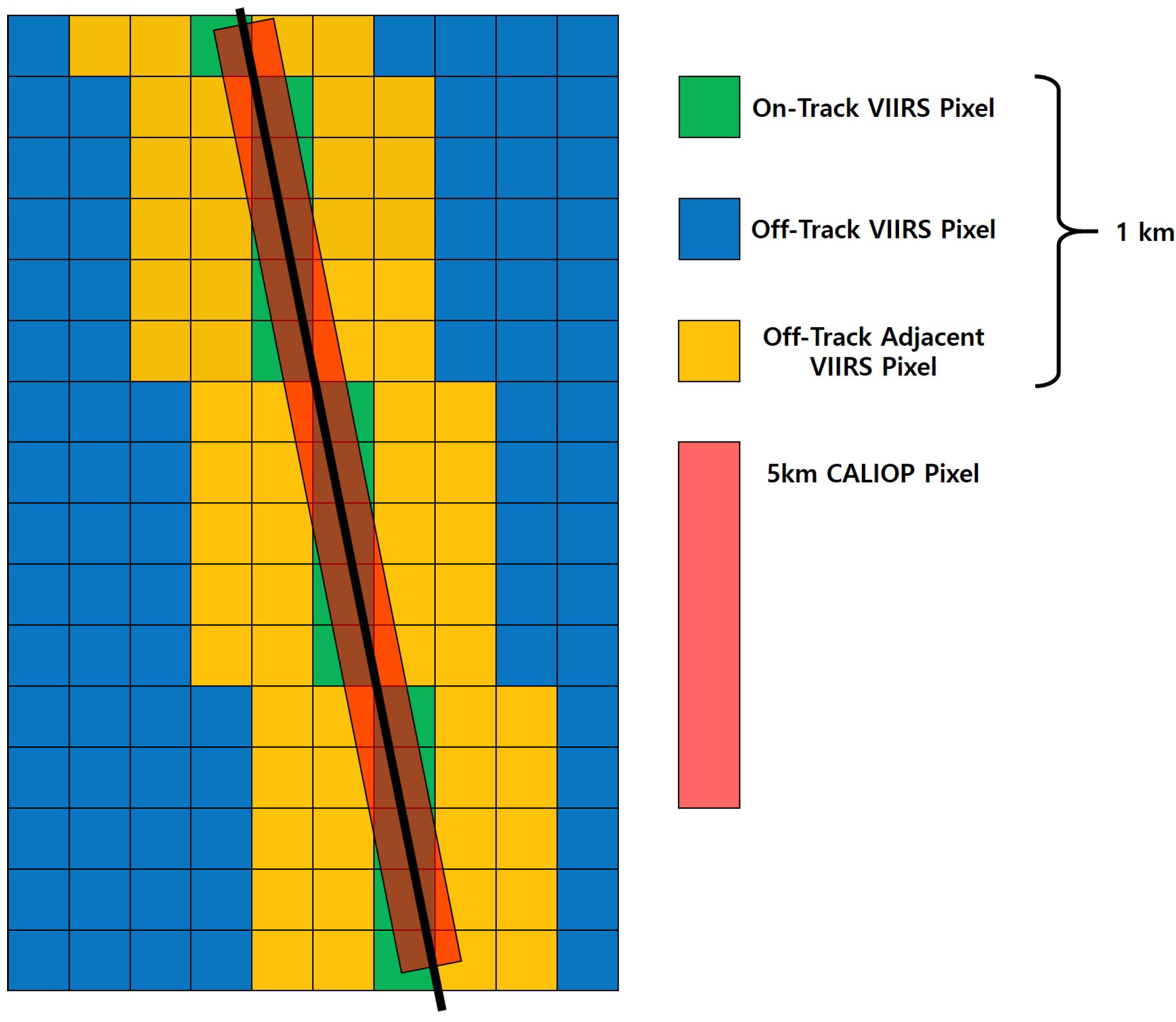
Figure 1. Illustration of on-track, off-track, and adjacent VIIRS pixels as well as CALIOP track.
Remotesensing 13 00456 g001
Figure 2. (a,b) Distribution of clear sky and dust over land and ocean, for both training and testing data. (c,d) distribution of dust for training and testing data. Spatial distribution is averaged with 5 × 5 latitude, longitude grid box.
Remotesensing 13 00456 g002
Figure 3. Accuracy of five different ML based models with different structures of predictor variables. Accuracy is calculated as total number of correct predictions (both clear sky and dust) divided by total number of test dataset. Accuracy plotted on top of each bar represents the highest accuracy among the different structures of predictor variables, for each of the methods. (a) Land; (b) Ocean; (c) Land + Ocean.
Remotesensing 13 00456 g003
Figure 4. (a,b) Spatial dust distribution for all test days. (a) CALIOP and (b) FFNN shows the dust distribution over CALIOP and VIIRS collocated track. Dust distribution is plotted with 5 × 5 lat-lon grid; (c) spatial difference between FFNN and CALIOP dust fraction; (d) monthly time series of CALIOP and FFNN dust fraction over the entire globe to show the seasonality.
Remotesensing 13 00456 g004
Figure 5. Comparison of CALIOP product, FFNN prediction, and PHYS prediction. First, two stacked bar graphs show the comparison between CALIOP and FFNN. Numbers in CALIOP bar show the percentage of dust and non-dust over the total number of CALIOP data, while the numbers in FFNN bars represent the conditional accuracy of the FFNN regarding CALIOP defined dusty or clear. Three stacked bars on the right depict the comparison between CALIOP, FFNN, and PHYS under the PHYS ADP cloud mask. Panel (a) shows the comparison over land, while panel (b) shows the comparison over the ocean.
Remotesensing 13 00456 g005
Figure 6. Predicted dust distribution for day (a) 075 (16 March 2014) and (b) 224 (12 August 2014). CALIOP and FFNN-onTrack shows the CALIOP product and FFNN prediction over the CALIOP and VIIRS collocated track, while FFNN-offTrack shows the FFNN prediction over the entire VIIRS granule for each day.
Remotesensing 13 00456 g006
Figure 7. Dust distribution of day 075 for (a) on-track CALIOP product, (b) on-track FFNN prediction, (c) off-track FFNN, and (d) off-track PHYS. Missing observations where there are no CALIOP overpass are marked as white.
Remotesensing 13 00456 g007
Figure 8. Dust distribution of day 224 for (a) on-track CALIOP product, (b) on-track FFNN prediction, (c) off-track FFNN, and (d) off-track PHYS. Missing observations where there are no CALIOP overpasses are marked as white.
Remotesensing 13 00456 g008
Figure 9. A case study over Arabian peninsular on day 224, at 10:24. (ad) depict images from Wisconsin’s VIIRS quicklook, where (a) represents the true color, (b) Clear Sky confidence, (c) Aerosol Optical Thickness, and (d) Angström Exponent; (e) FFNN results in the same geolocation. Results are plotted in a 0.1 × 0.1 latitude and longitude grid, and the percentage of dust within the grid are shown as colors. Thin magenta lines show the CALIOP swath of this region. Pixels within the magenta lines are the CALIOP product. (f) same as (e), but for the PHYS product.
Remotesensing 13 00456 g009
Figure 10. A case study over Arabian peninsular on day 075, at 04:54. (ad) depict an image from Wisconsin’s VIIRS quicklook, where (a) represents the true color, (b) Clear Sky confidence, (c) Aerosol Optical Thickness, and (d) Angström Exponent; (e) FFNN results on the same geolocation. Results are plotted in a 0.1 × 0.1 latitude and longitude grid, and the percentage of dust within the grid are shown as colors. Thin magenta lines show the CALIOP swath of this region. Pixels within the magenta lines are the CALIOP product. (f) same as (e), but for a PHYS product.
Remotesensing 13 00456 g010
Figure 11. A case study over Arabian peninsular on day 075, at 13:36. (ad) depict images from Wisconsin’s VIIRS quicklook, where (a) represents the true color, (b) Clear Sky confidence, (c) Aerosol Optical Thickness, and (d) Angström Exponent; (e) FFNN results on the same geolocation. Results are plotted in a 0.1 × 0.1 latitude and longitude grid, and the percentage of dust within the grid are shown as colors. Thin magenta lines show the CALIOP swath of this region. Pixels within the magenta lines are the CALIOP product; (f) same as (e), but for PHYS product.
Remotesensing 13 00456 g011
Table 1. Target variables used in the study based on CALIOP algorithm. Note that all cloudy-pixels are excluded from the study.
Target Variables
Non-DustNo aerosol detected,
Other types of Aerosols
DustPure Dust,
Dust mixtures,
Dust above or below other types of aerosols
Table 2. Predictor variables used in the study based on VIIRS measurement. Variables marked in bold represent the top nine features selected by RF, and variables marked in italic represent the top nine features selected by FFNN.
Predictor Variables
Radiances from VIIRS M-bands (16)
(band center in µm)M01 (0.412 µm), M02 (0.445 µm), M03 (0.488 µm), M04 (0.555 µm),
M05 (0.672 µm), M06 (0.746 µm), M07 (0.865 µm), M08 (1.240 µm),
M09 (1.378 µm), M10 (1.61 µm), M11 (2.25 µm), M12 (3.7 µm),
M13 (4.05 µm), M14 (8.55 µm), M15 (10.763 µm), M16 (12.01 µm)
Geometric Variables (4)Solar Azimuth Angle (SAA),
Solar Zenith Angle (SZA),
Viewing Azimuth Angle (VAA),
Viewing Zenith Angle (VZA)
Observation Information (3)Day of Year (1–365),
Latitude,
Longitude
Publisher’s Note: MDPI stays neutral with regard to jurisdictional claims in published maps and institutional affiliations.