Abstract
In this paper, the research of nonlinear cylindrical metastructure was obtained. An algorithm for finding the total field of a nonlinearly loaded perfectly conducting cylinder covered with a metamaterial (MM) layer based on Maxwell’s equations with nonlinear boundary conditions on the surface of nonlinear loads (NL) was developed. A software package implementing this algorithm was created. Based on the results of numerical calculations of the program, the scattering diagrams of a metal cylinder with NL, covered with a layer of MM at the fundamental, second, and third harmonics were obtained. The dependences of the harmonics of the scattered field on the parameters of nonlinear loads were also studied. With the help of numerical simulation using Ansys HFSS, the extract procedure of the effective parameters of cylindrical MM was realized. Based on the results of calculation and numerical simulation, a model of a nonlinear cylindrical structure of two radii was made and an experimental study was carried out. As a result of the experiment, the frequency characteristics of the metastructure were obtained at various angles of incidence of the wave. The results of numerical simulation were confirmed by the results of the experiment. It is shown that the use of the provided nonlinear cylindrical marker with metamaterial makes it possible to obtain the levels of the first and second harmonics in a scattered field of the same order. This structure can be used as a nonlinear marker in both military and civilian areas.
1. Introduction
Historically, nonlinear effects have been found in electrical circuits containing elements such as diodes, transistors, amplifiers, mixers, etc. The nonlinear properties of these elements are currently well understood. One of the less common mechanisms for causing harmonic distortion is passive intermodulation (sometimes the name “rusty bolt effect” [1,2] is preferred). Corroded materials on antennas, waveguides, or even structural elements can act like one or more diodes. Rusty objects that should not be in the signal path, including antenna structures, can also reradiate signals at harmonics and combination frequencies. However, nonlinear effects are not always undesirable. For example, it was proposed that we use these effects for target detection and tracking [3,4,5,6,7,8,9,10]. Today, the effect of a rusty bolt is used to search for insects [4,5,6,7,8], measure human medical indicators [10], in devices for finding people caught in natural disasters [3]. In turn, the automotive industry has received patents for detection using nonlinear tags since the 1970s [9]. Tags can be placed on vehicles or people in high traffic areas such as security guards, construction workers, police officers, etc. In this concept, nonlinear tracking is performed by marking the targets of interest with special nonlinear markers. Such markers allow converting the reflected signal to higher frequencies. Since the size of the antenna is in many cases proportional to the wavelength of the signal, increasing the frequency allows the size of the receiving antenna to be reduced when the receiving and transmitting channels are separated. Moreover, frequency conversion to higher frequencies allows a wider bandwidth to be used, increasing the information transfer rate. However, several issues arose when a nonlinear locator is used:
- A short locator range;
- An overlapping of the spectrum of the emitted signal and the spectra of nonlinear responses in the reception band of a nonlinear locator (since the reception of a useful signal from a nonlinear object is performed against the background of hum noise);
- A load of the radio range with radio sources for various purposes in the frequency range optimal for use in nonlinear radars.
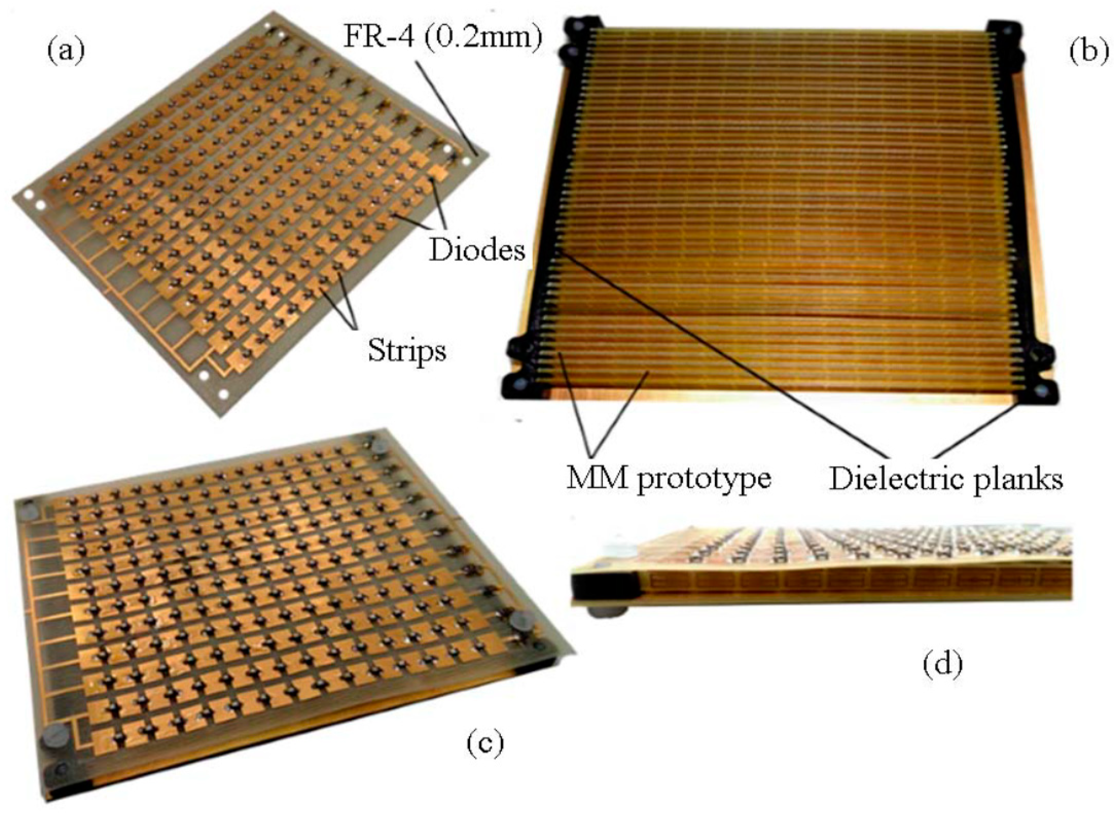
To isolate the nonlinear response from the frequency of the higher harmonic signal, it was proposed to use a nonlinear marker, which would be designed in such a way that it makes it possible to reduce the level of the reflected field at the fundamental frequency of the reradiated signal by several orders of magnitude. Previously, we proposed [11] to use as a nonlinear marker, a microstrip array with nonlinear loads (diods) in the plane of strips with a substrate made of a flat metamaterial (MM) [12]. The nonlinear marker is shown in Figure 1.

Figure 1.
A fabricated nonlinear structure, consisting of a microstrip array with diodes with a MM substrate: (a) a strip array with diodes; (b) a proposed MM substrate; (c) a nonlinear marker (top view); (d) a nonlinear marker (side view).
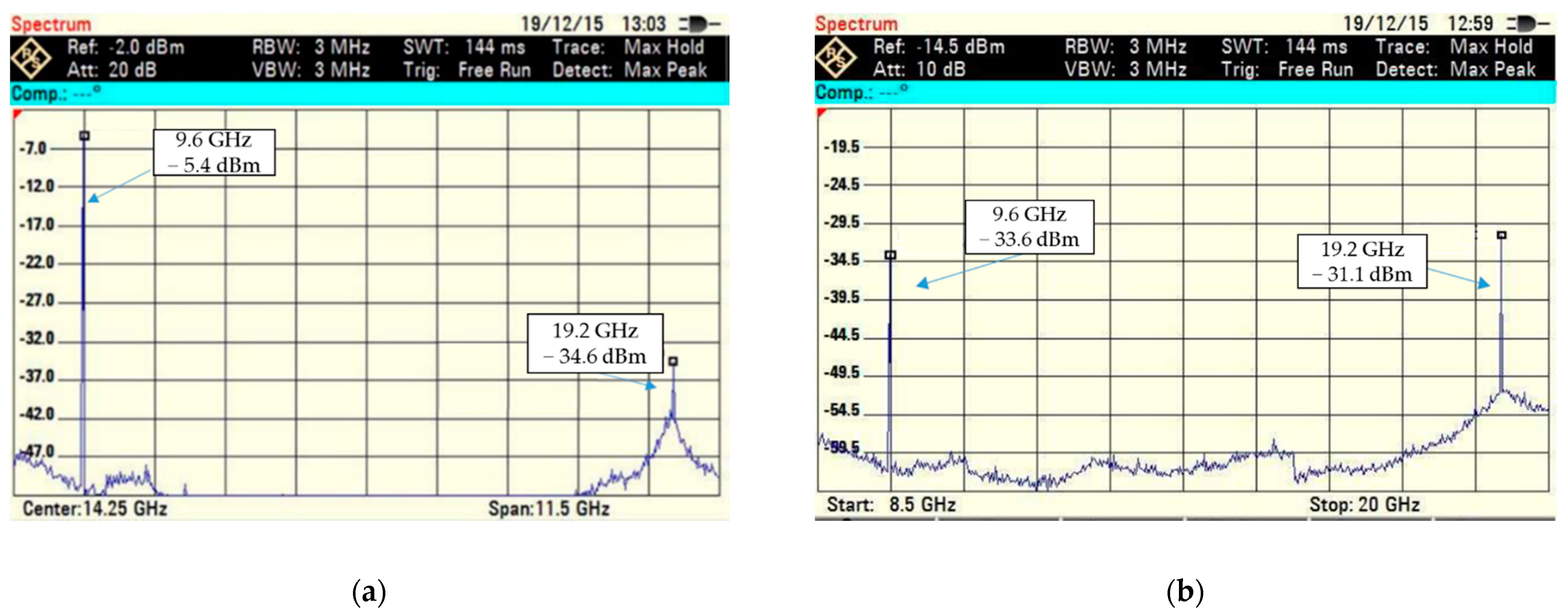
The use of such a nonlinear marker, due to the use of an MM substrate, as shown in Figure 2, made it possible to reduce the level of the reflected signal at the frequency of the emitted signal by 28 dB. The measured frequency characteristics of such markers are shown in Figure 2.
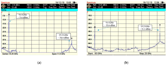
Figure 2.
Spectrum of the reflected field from a nonlinear marker, (a) with air substrate (b) with MM substrate.
However, when a marker is placed on a search object, it is often difficult to use flat structures, other nonflat structures are required. For example, as avalanche protection equipment, nonlinear cylindrical markers, “cuffs” that are worn on the arm, can be used.
We propose a nonlinear cylindrical marker using a metamaterial which provides increasing the signal-to-noise ratio at the input of the receiver of a nonlinear locator (compared to a conventional cylindrical marker without the use of metamaterial), and as a consequence, increasing the range of a nonlinear locator operation.
2. Materials and Methods
2.1. Nonlinear Boundary Conditions
The development of a nonlinear marker is based on a rigorous theoretical approach using Maxwell’s equations, nonlinear boundary conditions, and the method of integral equations.
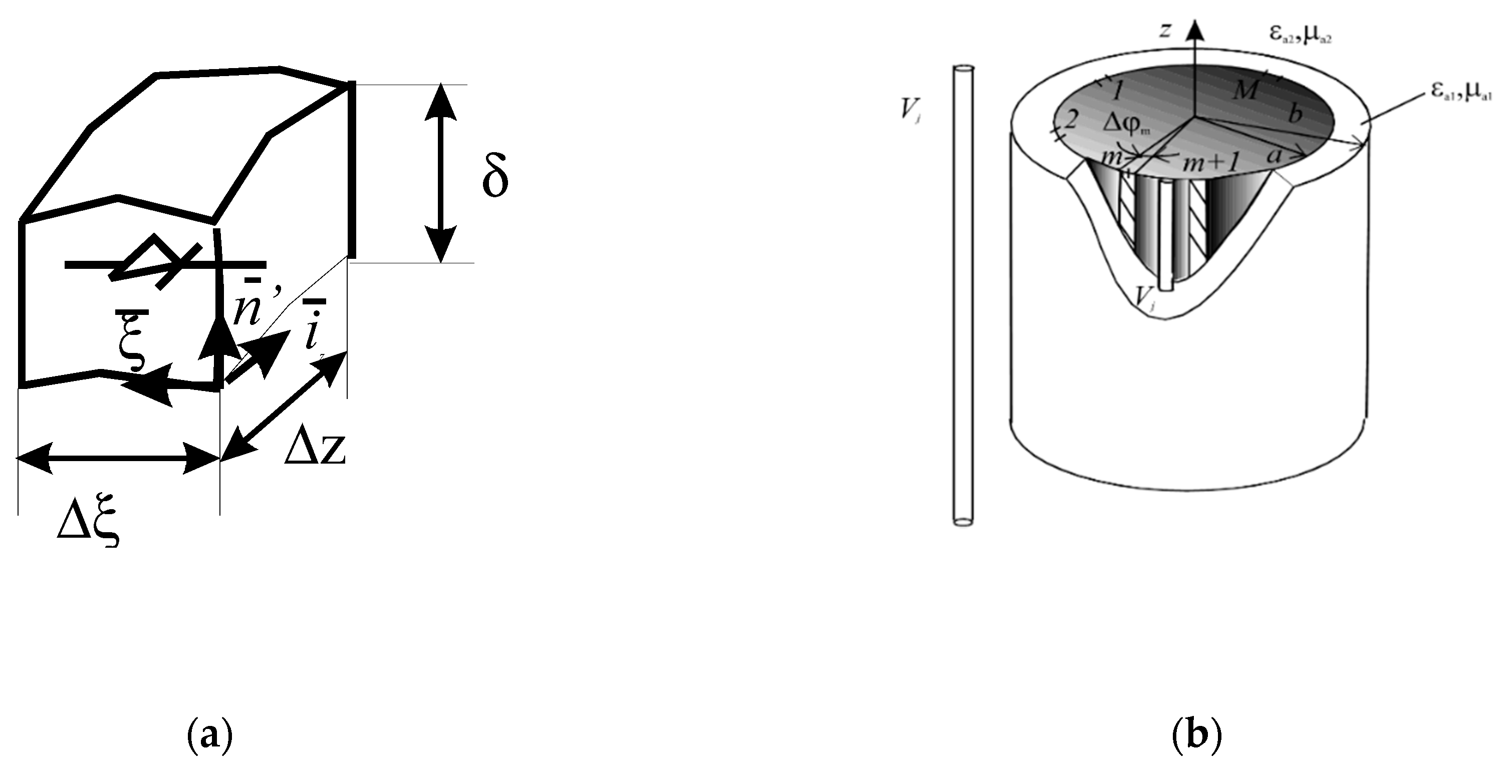
Let us consider how distributed nonlinear loads are represented by nonlinear boundary conditions using the example of a distributed nonlinear load in the form of a nonlinear contact formed in a narrow gap between two extended metal objects. It is known [13,14] that electric charges tunnel in this case across the slot. For such nonlinearities, the following mathematical models are applied. At first, we will consider a longitudinal surface nonlinear load located along z ( < z < ) and are in general case nonhomogeneous along z. Let us divide the load into elementary sites with length within the limits of which the currents and potential differences between load edges are assumed to be constant. Let us consider one site. For such a site, the applied mathematical model is shown in Figure 3a.

Figure 3.
Mathematical model of nonlinear load (a) Geometry of the problem (b).
It is convenient to take local curvilinear coordinate system . The field penetration depth in contact along the normal is small and the current volume density along this coordinate can be expressed through the delta function. Here the electric current can flow along the ξ coordinate while the magnetic one along z.
For each such elementary site V-I characteristic is given as:
where U are the electric current through the load and the voltage on the load edges, are the V-I characteristic parameters. We take M = 3. The electric current and voltage can be expressed by the surface densities J of electric and magnetic currents as follows:
where is Lame coefficient. Substituting them into the ratio (1) we will receive:
Turning to complex amplitudes, decomposing the temporary functions in Fourier series, and taking into account the rule of power function decomposition we will obtain the local boundary condition for surface currents:
where are harmonic numbers (for Fourier series),
ω is the cyclic frequency of the primary source.
2.2. Formulation of the Problem
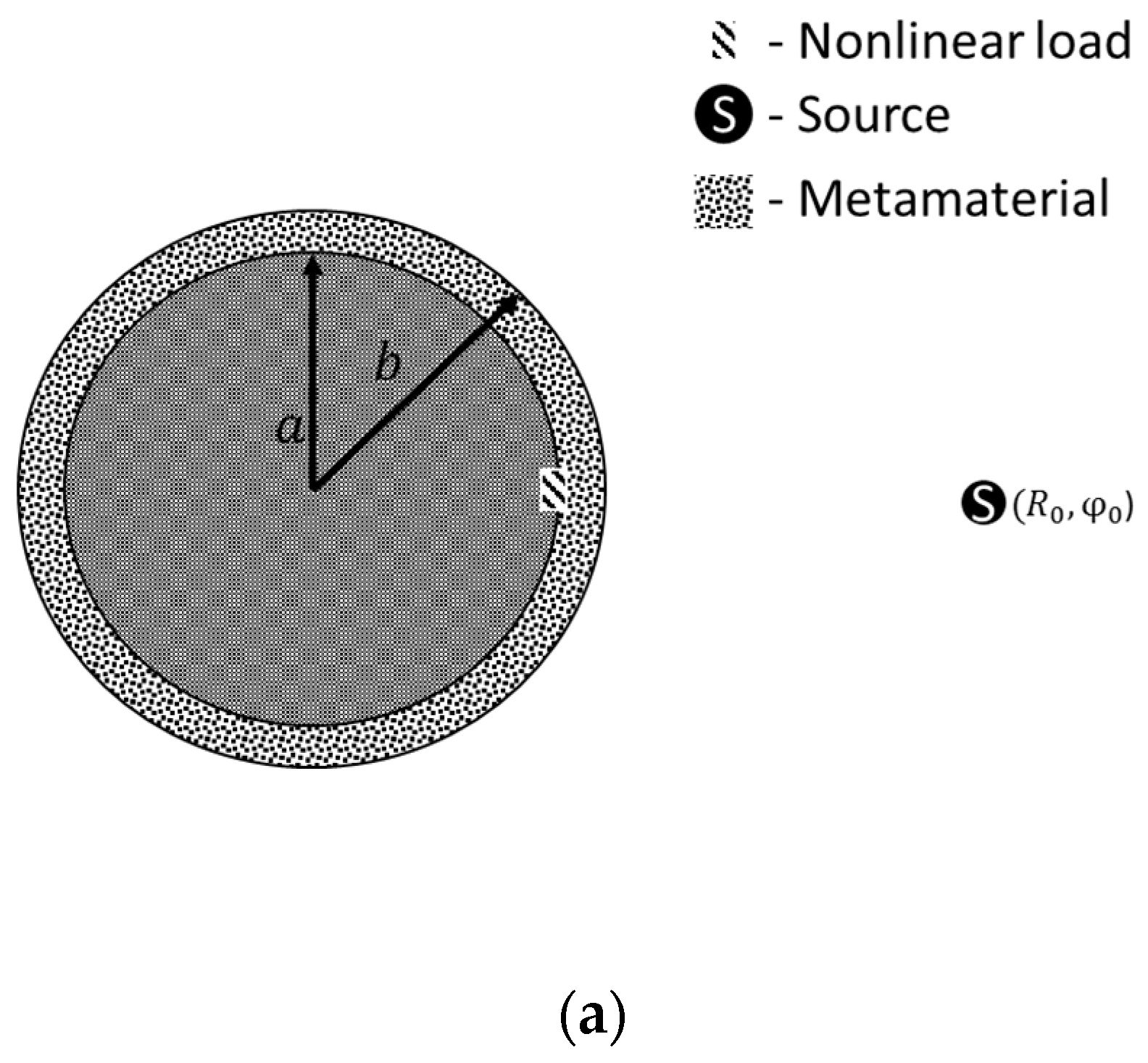
Let us have the surface of a perfectly conducting circular infinite cylinder of radius , on which on which M longitudinal (parallel generatrix) homogeneous nonlinear loads are located. Let us introduce a cylindrical coordinate system (CCS) with the z-axis aligned with the cylinder axis (Figure 3b).
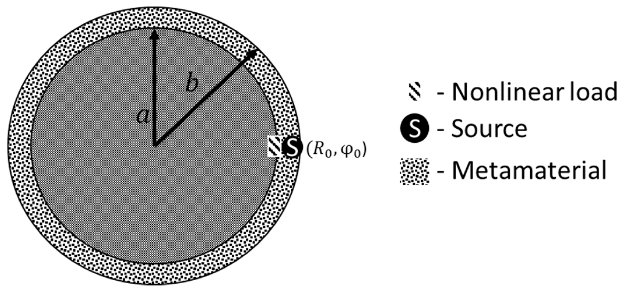
Let us denote the loads by narrow nonlinear slots and define the coordinates of the loads as, , are the load angular widths. I-V characteristics of the form (1) are set for the loads. The cylinder is covered with a layer with parameters outer radius . The primary source at frequency ω is placed in a volume Vj that is uniform along the z coordinate. The problem is to find the field strength at the fundamental and harmonic frequencies at the observation point p for a given external source in the presence of a given object, taking into account the external volume with homogeneous parameters εa2, μa2.
2.3. Solution of the Problem by the Method of Integral Equations
Let us denote the area inside the dielectric coating as and the outside as . Let the source is in the domain . Then, taking into account the integral relations for the fields in the domains and the continuity conditions for the components of the tangent vectors of the field on the surface S for r = b, putting the observation point on the surface S, we get:
where are vectors of the auxiliary fields excited by an elementary magnetic radiator located at the point (whose parameters do not depend on z).
are the surface currents densities on S at r = b + 0, r = b − 0; are the surface current densities at nonlinear loads.
It is assumed that because of the narrow gap along φ, the magnetic current flows only along z, the last integral can be represented as a sum of integrals:
Putting the observation point on the surface of the qth nonlinear load using the integral relations for the fields [15], we obtain
Using the nonlinear boundary conditions described earlier on the surface of the qth nonlinear load and performing the same procedure for M loads, we obtain:
Equations of type (5) and (8) constitute an infinite system of nonlinear integral equations for unknown currents on the surfaces S and S1.
If the cylinder is excited by a source located in the domain , the procedure for obtaining the system of equations is similar to that described earlier, we get equations of the form:
2.4. Defining Auxiliary Fields
As the auxiliary fields , we take the fields of the in-phase magnetic current filament placed between two coaxial perfectly conducting cylinders with radii a и b at frequencies nω. The space between the cylinders is filled with a homogeneous medium with parameters , ). Then, if the medium is “Double negative” (DNG) at one frequency,
and at the other frequency it is an ordinary dielectric, then:
As an auxiliary fields we take the fields of the magnetic current in-phase filament, excited at frequencies nω, in the presence of a perfectly conducting cylinder of radius b (in the center of CCS), placed in a space with parameters . Taking into account the auxiliary components of the fields, the first integral on the right-hand side of (5) contains only the term , the first integral on the right-hand side of (8) contains only the term . In the same way, we transform Equations (9) and (10).
Auxiliary fields in volume are the fields of the in-phase magnetic current filament located between two coaxial perfectly conducting cylinders with radii a and b, excited at frequencies nω. They must satisfy the boundary conditions for the tangential component of the vector , for r = a,b. It can be written as:
Here are propagation constants and characteristic impedances in volumes ; are Bessel and Hankel functions.
2.5. Algorithmization of the Problem
Consider the solution of a system of nonlinear integral equations with the method of moments. We take piecewise constant functions as basis functions for unknown currents. We take the δ-function as a test function. Then from (9), (10) we obtain a system of nonlinear algebraic equations (SNAE):
and from (9), (10) we obtain the SNAE:
When the cylinder is excited by a magnetic current filament with coordinates we have:
where is the Kronecker symbol.
Solving SNAE (14), (15) we obtain the unknown values of the harmonics of surface currents on loads and on the cylinder cover.
2.6. Description of MM
The coating of the nonlinear cylinder is realized in the form of DNG-structure [12]. The unit cell of such a structure is a ring resonator, which provides negative values of the magnetic permeability, and a linear conductor, which provides negative values of the dielectric constant. The resonator and the line conductor are placed on a dielectric substrate made of FR-4 material. An infinite structure model of such elements was analyzed using an electrodynamic design package that uses the method of moments.
Numerical analysis of the model of an infinite lattice of MM is carried out using HFSS. During the simulation, the complex reflection and transmission coefficients of the MM are obtained. On this basis, using the method of homogenization of MM parameters, which are proposed in [16], the effective values of the parameters are calculated (Table 1).

Table 1.
Calculated effective parameters of MM.
The results of numerical simulations show that the MM at the frequency of the fundamental harmonic works like a DNG material, and at the second harmonic it acts like an ordinary dielectric. This feature of MM is the main interest in the study of its influence on nonlinear structures.
2.7. Radiation Patterns and Scattering Diagrams of a Nonlinear Cylinder Covered with an MM Layer
Let us investigate the problem of excitation and scattering of a nonlinear cylinder covered with an MM layer described in Section 2.3.
The resulting SNAE (14), (15) was solved numerically using the developed C ++ program. The program is based on Broyden’s method [17]. The software package allows to calculate the total field of a cylinder covered with a layer of metamaterial, taking into account the position of nonlinear loads when excited by a magnetic current filament, at a given number of harmonic frequencies. The program provides for changing the parameters of the I-V characteristic of nonlinear loads, changing the radius of the cylinder, the thickness of the coating, the amplitude of the external current, the position of the source, and the position of the observation point.
At the first stage, a study of the radiation patterns and scattering of the cylinder with a nonlinear load covered with a MM layer, described in Section 2.3, was carried out. Consider a situation where the source of an excitation is within the metamaterial. The parameters of such calculation are presented in Table 2. The geometry of the problem is shown in the Figure 4.
Table 2.
Parameters of calculation.

Figure 4.
The geometry of the problem.
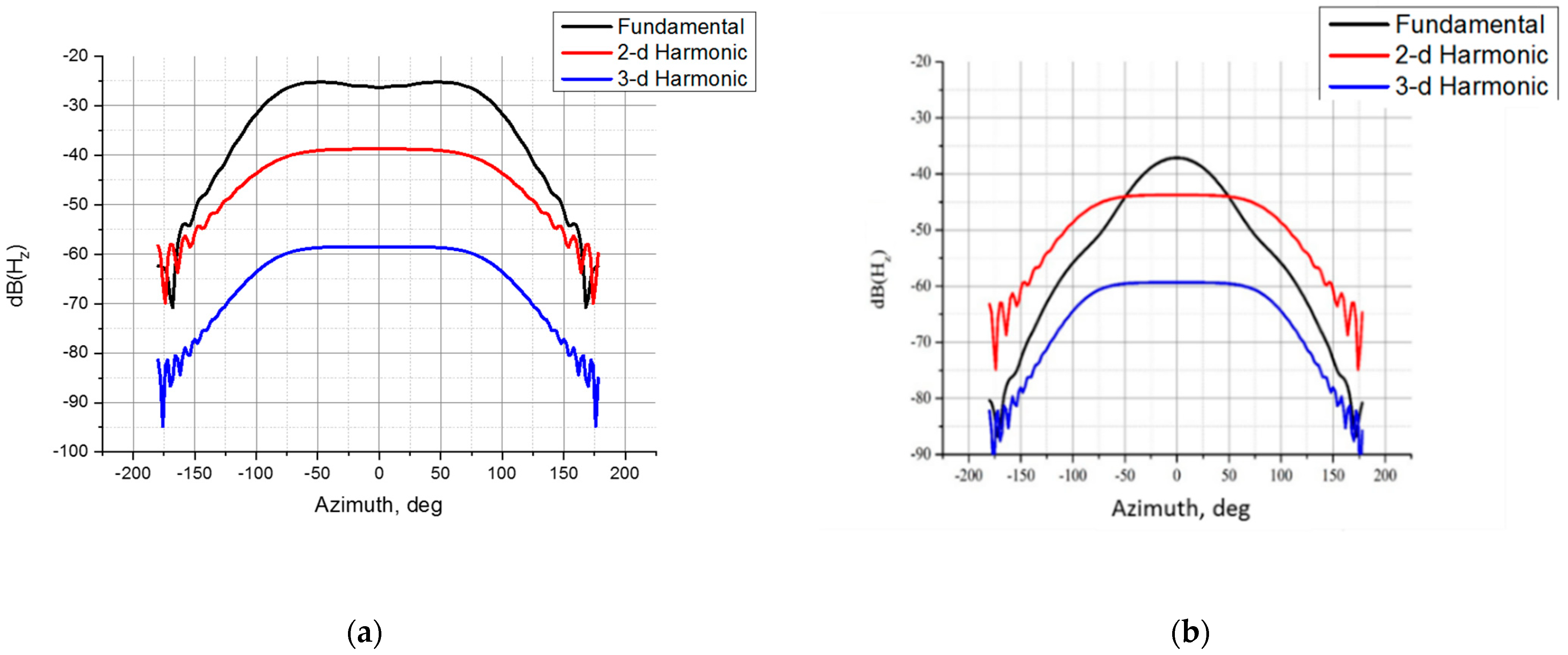
As a result of the program calculation, the radiation patterns of the cylinder were obtained at the fundamental frequency and at the frequency of multiple harmonics (2nd and 3rd) (Figure 5).
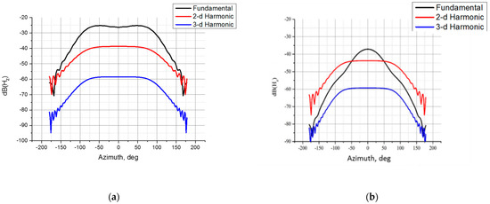
Figure 5.
Radiation patterns of the cylinder at the three harmonics of the field: (a) without coating, (b) with MM coating.
It follows from the figure that the use of MM leads to a narrowing of the pattern at the fundamental frequency and a decrease in the field level by 12 dB. At the same time, the second harmonic level decreased by 5 dB. This made it possible to obtain in a certain sector of angles the values of the second harmonic exceeding the level of the 1st harmonic. The use of the MM layer allows the level of higher harmonics to be equalized with respect to the fundamental frequency in a wide sector of angles, which, in turn, will allow obtaining a gain in the signal-to-noise ratio in the receiver relative to the uncoated case.
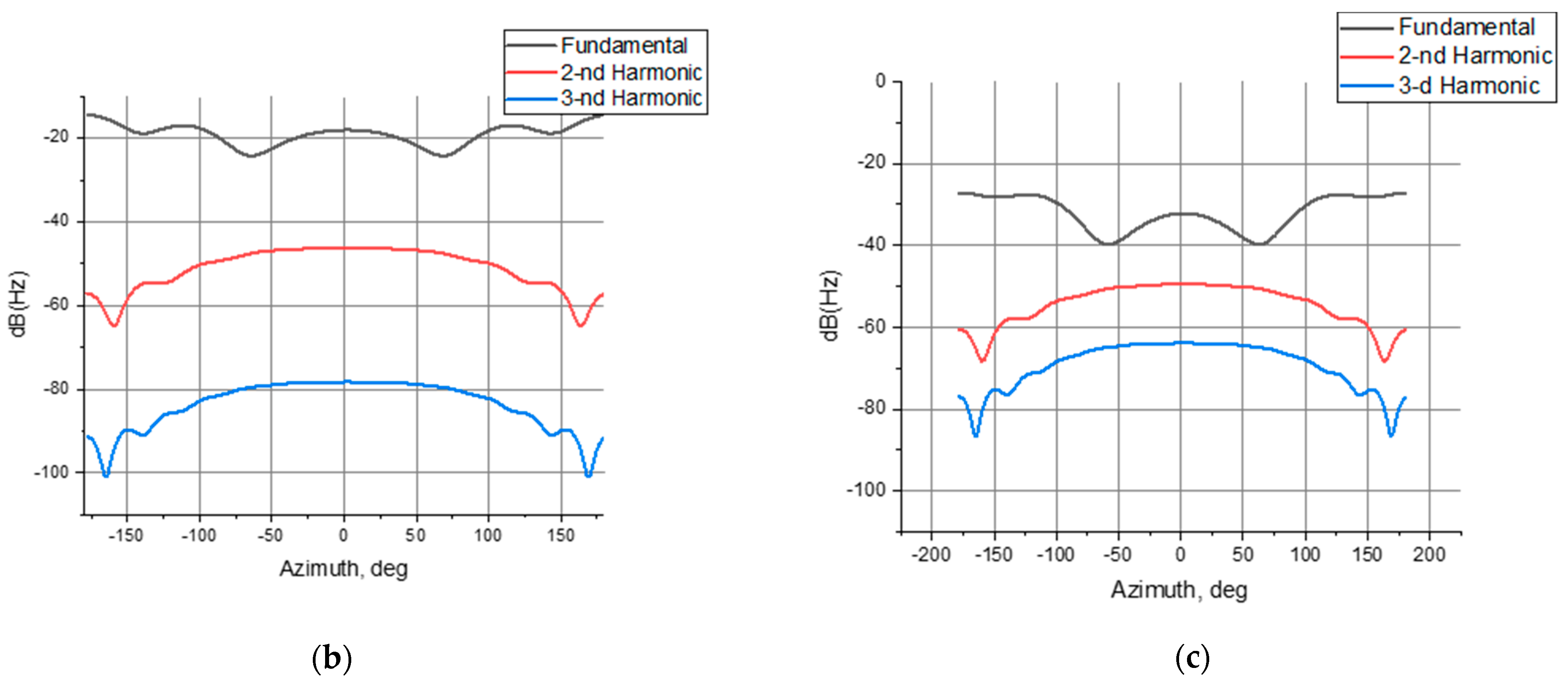
Scattering diagrams were also obtained (Figure 6). The parameters of the problem are similar to those given in Table 2, except for the position of the source. The source was located at the point .

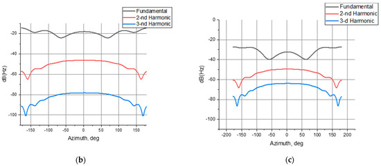
Figure 6.
Geometry of the problem (a) Scattering diagrams of the cylinder at the three harmonics of the field, (b) without coating, (c) with MM coating.
As can be seen from the figure, the use of the proposed MM makes it possible to reduce the level of the fundamental harmonic in the entire range of angles by more than 10 dB. In this case, there is an increase in the level of the third harmonic.
The results obtained using the software package confirm the hypothesis of an increase in the relative level of harmonic components in the scattered field for a nonlinear marker. Let us conduct an experimental study to confirm the simulation result.
3. Results
3.1. Experimental Studies of a Fabrication Sample of a Cylindrical MM
The purpose of the experiment was to confirm the possibility of using the proposed MM in a cylindrical design to increase the relative level of harmonic components in a scattered field. For this, two cylinders with an outer radius of 35 mm and a radius of 45 mm were made. A photograph of a fabrication sample of a cylindrical structure is shown in Figure 7.
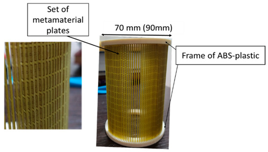
Figure 7.
Photo of a cylindrical structure based on a set of MM plates presented in [12].
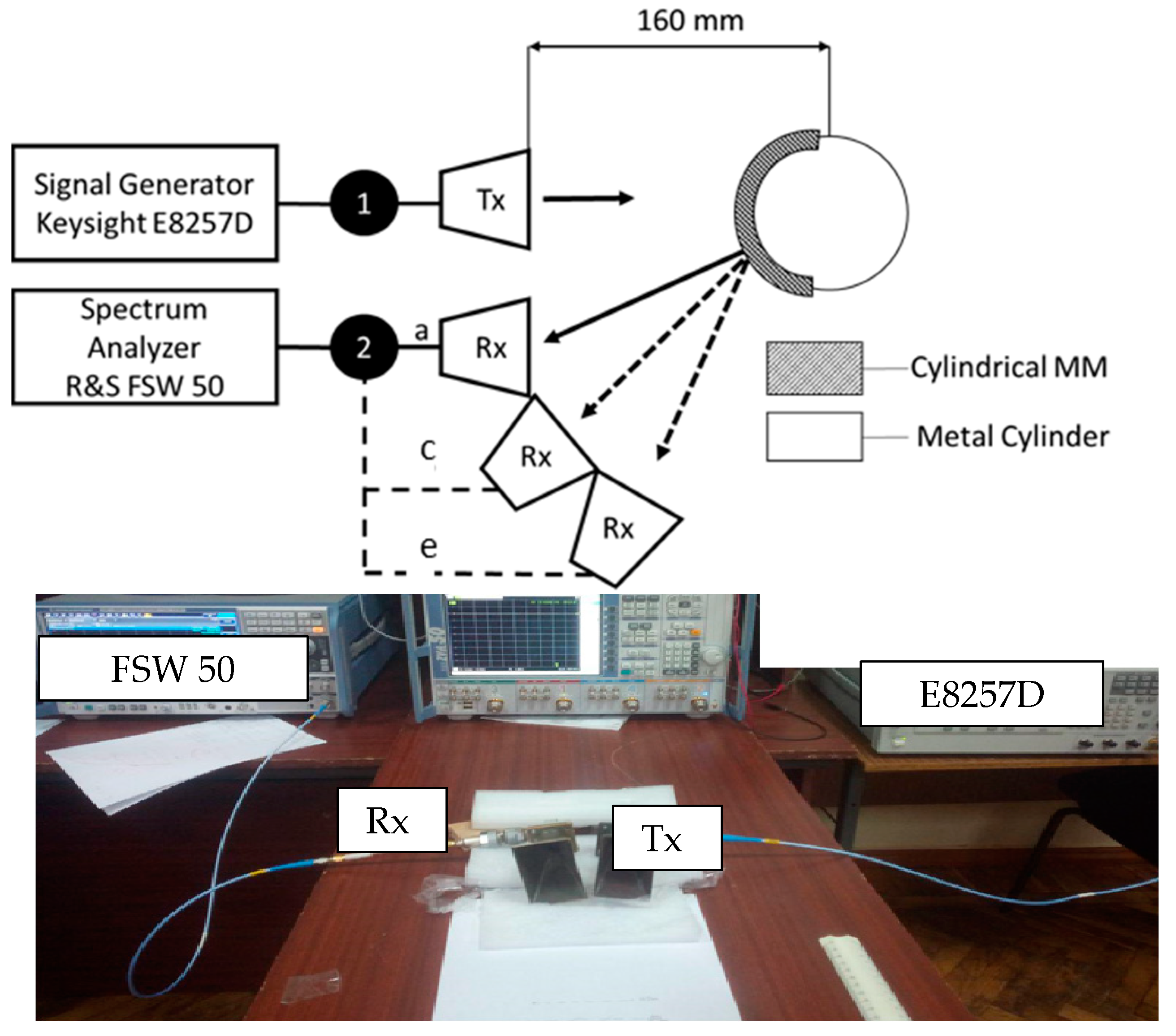
To investigate the frequency-selective properties of the cylindrical structure, the transmission coefficient was measured for different angles of incidence. The setup consisted of a Keysignt E8257D high-frequency signal generator, an SMA-N-type cable assembly (1,2), an FSW 50 spectrum analyzer, and broadband X-Ka-band horn antennas. The set-up is shown in Figure 8.

Figure 8.
Measuring setup.
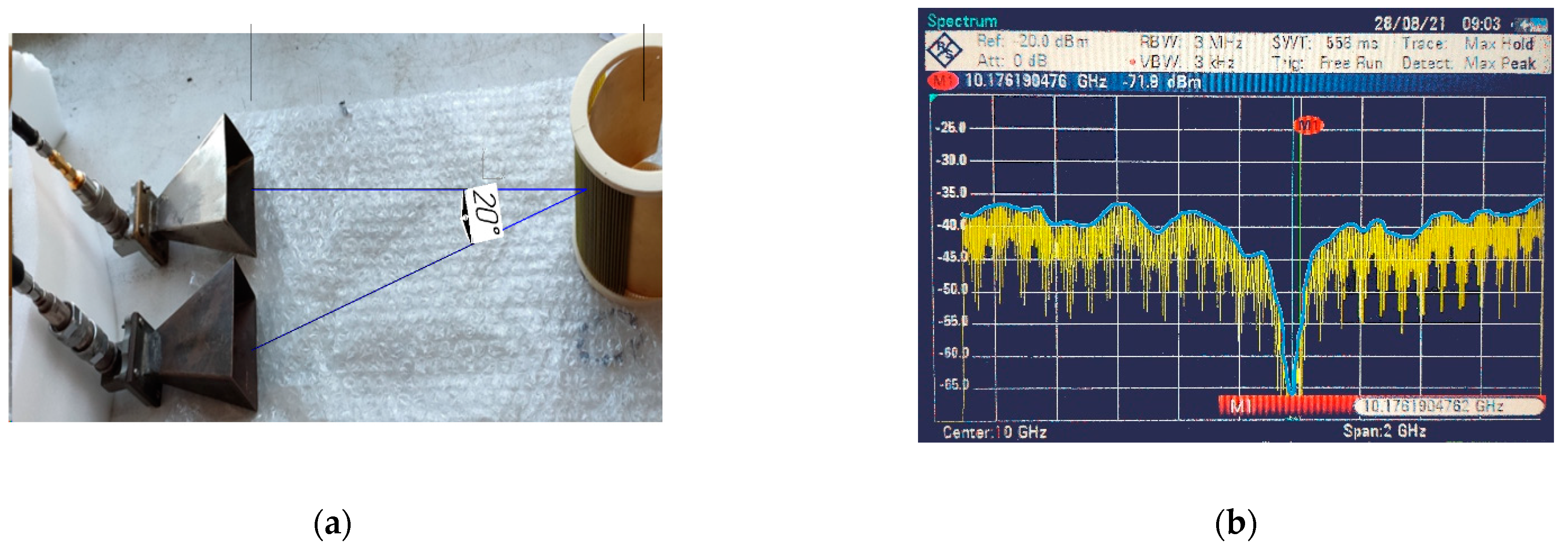
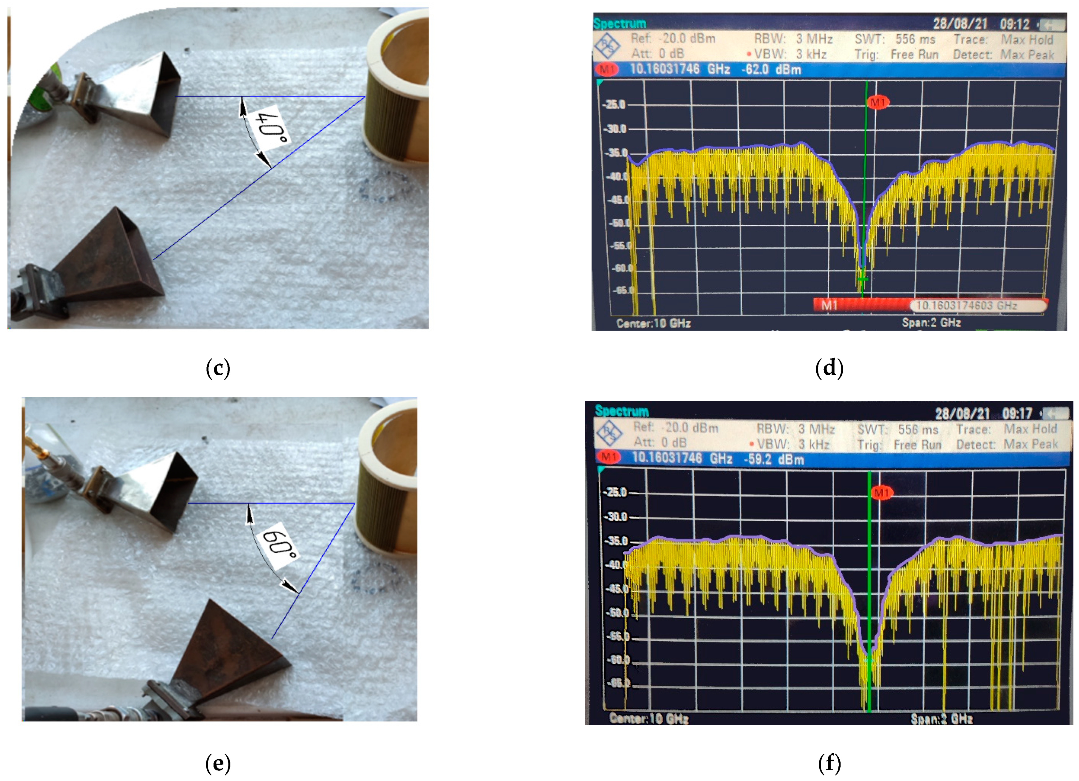
The horn antenna (Tx) radiated a monochromatic wave in the direction of the test fabrication sample. The field scattered from the nonlinear structure was received using a receiving horn antenna (Rx) connected to a spectrum analyzer. The measurements were carried out in the frequency range of 9–11 GHz. For the three positions of the transmitting horn (Tx), the absolute power values were found at a distance of 160 mm. The results are shown in Figure 9.


Figure 9.
Photo of the experimental setup for the measuring the field scattered from the fabrication sample of a cylindrical MM at an angle of incidence: (a) 20°; (c) 40°; (e) 60°; frequency characteristics of the power received by the antenna of the field scattered from the model with a cylindrical MM at an angle of incidence: (b) 20°; (d) 40°; (f) 60 °.
As can be seen from Figure 9b, at an angle of incidence of 20°, the greatest absorption of electromagnetic energy −71.9 dBm occurs in MM at a frequency of 10.16 GHz, which is 30 dB below the average reflection level in the same range. With an increase in the angle of incidence, the relative level of absorption at the resonant frequency decreases: 27 dB and 22 dB at angles of incidence of 40° and 60°, respectively.
3.2. Experimental Study of a Nonlinear Structure Covered with an MM Layer
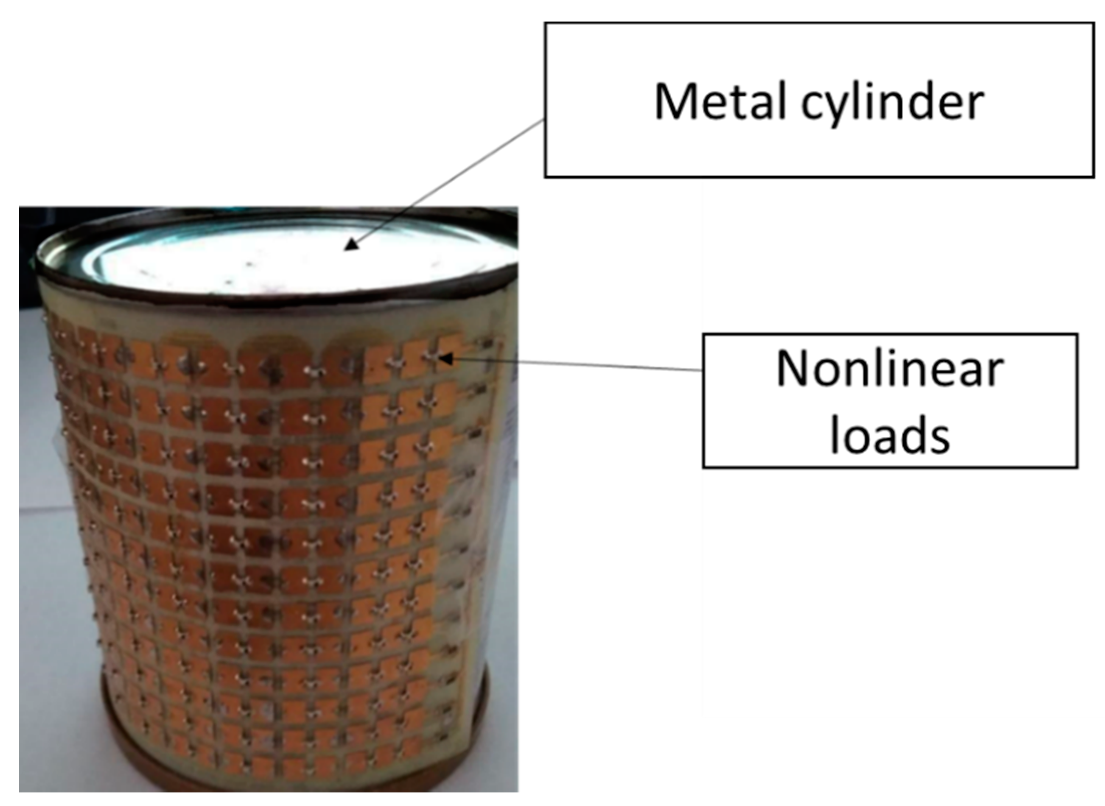
The cylinder with nonlinear loads, covered with a layer of metamaterial, presented in Figure 10, was experimentally studied. The fabrication sample consists of a metal cylinder with a radius of 35 mm with sites for diodes on the upper part of a dielectric substrate made of FR-4 material with a thickness of 0.2 mm. The height of the model of the metal cylinder with nonlinear loads was 120 mm. The 3A206A-6 Schottky detector diodes are included on the seats, which provide the transfer of energy from the frequency of the incident field f1 to the harmonic component 2f1.

Figure 10.
Photo of a metal cylinder with nonlinear loads.
To obtain greater accuracy and reduce the signal-to-noise ratio, measurements were carried out in a narrow frequency band. Before starting the measurements, the second harmonic level created by the generator itself was investigated. For this, instead of a fabrication sample of a nonlinear structure, a metal sheet of the same size was taken and a harmonic signal with a frequency of F = 10 GHz was supplied from the generator. We made sure that the level of the scattered field of the second harmonic is acceptable and does not exceed −70 dBm.
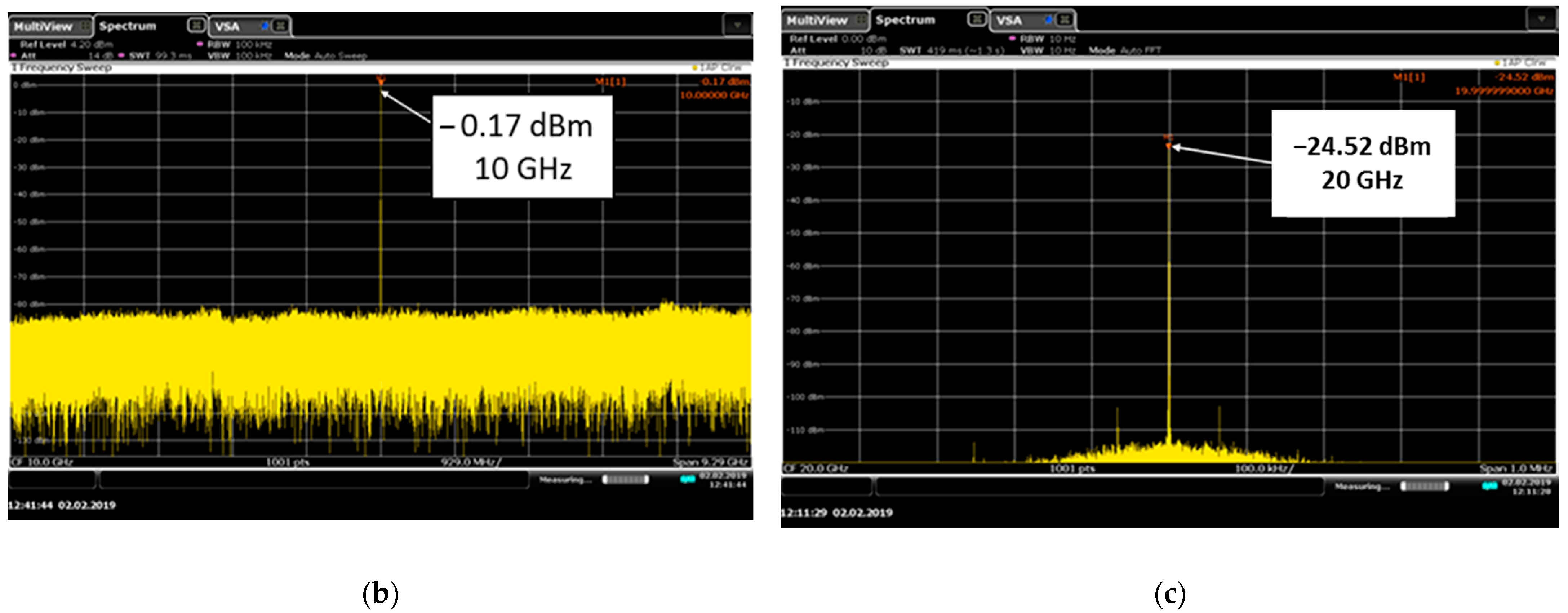
To determine the effect of MM coating on the scattering properties of a nonlinear structure, the frequency response of the scattered field of a nonlinear cylindrical structure without MM at the fundamental and second harmonics were measured (Figure 11). Measurements have shown that a metal cylinder with nonlinear loads of a radius of 35 mm creates a second harmonic in the scattered field 24.5 dB below the fundamental.
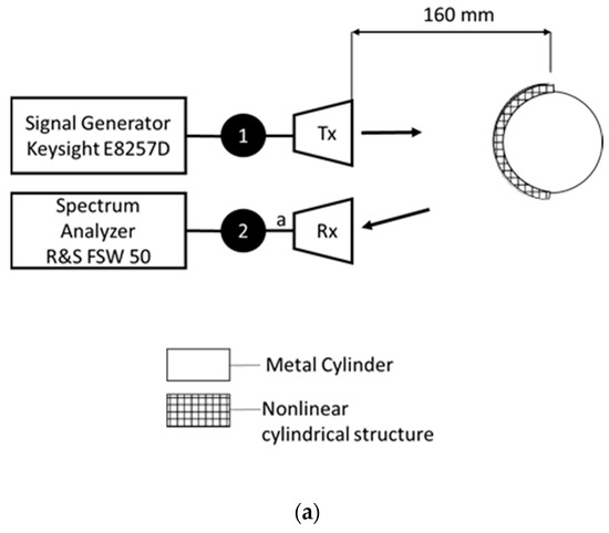
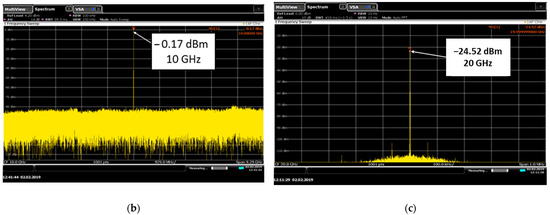
Figure 11.
(a) The experimental setup for measuring the spectrum of the scattered field from a cylindrical nonlinear structure; levels of the first and second harmonics of the field scattered from a cylindrical nonlinear structure without MM: (b) near to the fundamental frequency and (c) and near to the second harmonic.
3.3. Experimental Study of a Cylindrical Nonlinear Structure Covered with an MM Layer
After analyzing the characteristics of the cylindrical MM, the characteristics of the cylindrical MM with nonlinear loads were measured. A nonlinear cylindrical structure with radii of 35 and 45 mm was installed in special holes in frames made of ABS plastic. The scheme for measuring the scattered field is shown in Figure 12.
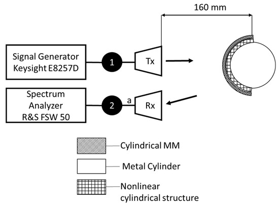
Figure 12.
Scheme for measuring the spectrum of the scattered field from a cylindrical nonlinear structure with MM.
To reduce the difference between the fundamental and the second harmonic, an MM coating, measured earlier, was added. The measurement was carried out with a power input to the horn antenna of 20 dBm (100 mW). To obtain greater accuracy, measurements for the first and second harmonics were carried out in a narrow frequency band (Figure 13).
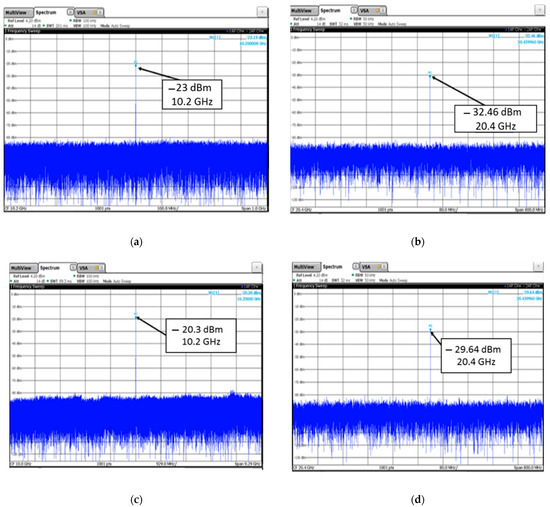
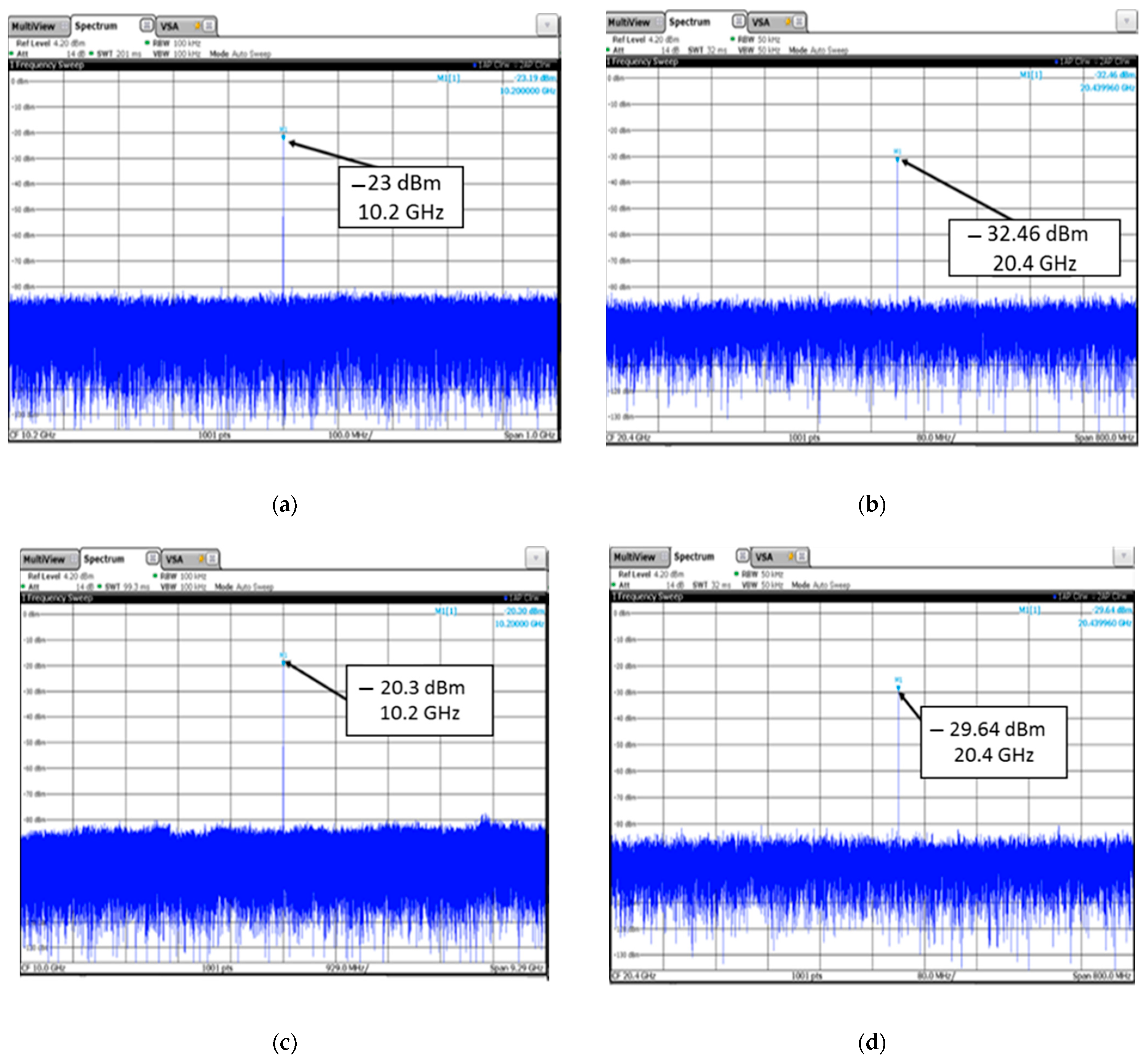
Figure 13.
Levels of the field scattered from a cylindrical nonlinear structure with MM (a) for a cylinder with radius 35 mm at the fundamental frequency and (b) on the second harmonic; (c) for radius 45 mm at the fundamental frequency and (d) on the second harmonic.
The level of the field first harmonic for a cylinder with a radius of 35 mm decreased by 23 dB in comparison with the measurement without MM. At the same time, the second harmonic level lowered by only 5 dB compared to the uncoated level. For a cylinder with a radius of 45 mm, the difference between the level of the first and second harmonics was 9 dB. Thus, an increase in the relative level of the second harmonic was demonstrated when using a cylindrical coating made of MM. The diminution in the absolute level of the field at the second harmonic is a consequence of high dissipative losses in the dielectric caused by the high value of the dielectric loss tangent tan δ = 0.02 as well as with the decrease in the power driving diodes (in comparison with the case without a coating) associated with the absorption of energy in the MM. To decrease the second harmonic of the field to be less, it is required to use high-frequency dielectric materials with a low value of the dielectric loss tangent tan δ = 0.0023 for example, ceramic dielectrics of Rogers, Arlon, and Taconic firms.
4. Conclusions
In this paper, the nonlinear cylindrical marker was introduced. The development of the nonlinear marker model was based on a rigorous theoretical approach using nonlinear boundary conditions. The resulting system of nonlinear integral equations was transformed into a system of nonlinear algebraic equations, which were solved using a developed program based on Broyden’s method. Radiation and scatter patterns of a cylinder with nonlinear loads were obtained using the software package. The calculation showed the possibility of an alignment of the harmonic component levels in the scattered field when using a MM coating. Experimental studies of the fabrication sample of a nonlinear cylindrical marker also demonstrated the possibility of an alignment between the harmonic level in the scattered field. The proposed nonlinear marker can be used to combat the overlap of the spectrum of the emitted signal and the spectra of nonlinear responses in a nonlinear locator.
Author Contributions
Conceptualization, D.V.S. and N.N.G.; methodology, D.V.S.; software, N.N.G.; validation, D.V.S. and N.N.G.; formal analysis, D.V.S. and N.N.G.; investigation, D.V.S. and N.N.G.; resources, N.N.G.; data curation, N.N.G.; writing—original draft preparation, N.N.G.; writing—review and editing, D.V.S.; visualization, N.N.G. All authors have read and agreed to the published version of the manuscript.
Funding
The research was carried out at the Laboratory of Communication Systems, Institute of Radio Engineering Systems and Control, Southern Federal University, Rostov-on-Don, Russia and was funded by Priority 2030 National Program.
Institutional Review Board Statement
Not applicable.
Informed Consent Statement
Not applicable.
Data Availability Statement
All measurement data are stored in the Share Scientific Center “Applied Electrodynamics and antenna measurements,” Southern Federal University, Russia.
Conflicts of Interest
The authors declare no conflict of interest.
Appendix A
The coefficients for SNAE (14) are as follows:
References
- Watson, A.W.D. Improvements in the Suppression of External Nonlinearities (“Rusty Bolt” Effect) which Affect Naval Radio System. In Proceedings of the 1983 IEEE International Symposium on Electromagnetic Compatibility, Arlington, VA, USA, 23–25 August 1983; pp. 157–160. [Google Scholar]
- Tromp, L.D.; Rudko, M. Rusty Bolt EMC Specification Based on Nonlinear System Identification. In Proceedings of the International Symposium on Electromagnetic Compatibility, Boston, MA, USA, 20–22 August 1985; pp. 419–425. [Google Scholar]
- Grasegger, K.; Strapazzon, G.; Procter, E.; Brugger, H.; Soteras, I. Avalanche Survival after Rescue with the RECCO Rescue System: A Case Report. Wilderness Environ. Med. 2016, 27, 282–286. [Google Scholar] [CrossRef] [PubMed] [Green Version]
- Brazee, R.D.; Miller, E.S.; Reding, M.E.; Klein, M.G.; Nudd, B.; Zhu, H. A transponder for harmonic radar tracking of the black vine weevil in behavioral research. Trans. Am. Soc. Agric. Eng. 2005, 48, 831–838. [Google Scholar] [CrossRef]
- O’Neal, M.E.; Landis, D.A.; Rothwell, E.; Kempel, L.; Reinhard, D. Tracking insects with harmonic radar: A case study. Am. Entomol. 2004, 50, 212–218. [Google Scholar] [CrossRef] [Green Version]
- Psychoudakis, D.; Moulder, W.; Chen, C.C.; Zhu, H.; Volakis, J.L. A portable low-power harmonic radar system and conformal tag for insect tracking. IEEE Antennas Wirel. Propag. Lett. 2008, 7, 444–447. [Google Scholar] [CrossRef]
- Aumann, H.; Kus, E.; Cline, B.; Emanetoglu, N. A low-cost harmonic radar for tracking very small tagged amphibians. In Proceedings of the 2013 Internation Instrumentation and Measurement Technology Conference, Minneapolis, MN, USA, 6–9 May 2013; pp. 234–237. [Google Scholar]
- Aumann, H.M.; Emanetoglu, N.W. A wideband harmonic radar for tracking small wood frogs. In Proceedings of the 2014 IEEE Radar Conference, Cincinnati, OH, USA, 19–23 May 2014; pp. 0108–0111. [Google Scholar] [CrossRef]
- Shefer, J.; Staras, H. Harmonic Radar Detecting and Ranging System for Automotive Vehicles. U.S. Patent 3,781,879, 25 December 1973. [Google Scholar]
- Chioukh, L.; Boutayeb, H.; Deslandes, D.; Wu, K. Noise and sensitivity of harmonic radar architecture for remote sensing and detection of vital signs. IEEE Trans. Microw. Theory Tech. 2014, 62, 1847–1855. [Google Scholar] [CrossRef]
- Semenikhina, D.V.; Chikov, N.I.; Semenikhin, A.I.; Gorbatenko, N.N. Experimental studies of nonlinear metasurface with metamaterial substrate. In Proceedings of the 2016 24th Telecommunications Forum (TELFOR), Belgrade, Serbia, 22–23 November 2016; pp. 1–4. [Google Scholar] [CrossRef]
- Lee, H.-M.; Lee, H. A Metamaterial Based Microwave Absorber Composed of Coplanar Electric-Field-Coupled Resonator and Wire Array. Prog. Electromagn. Res. C 2013, 34, 111–121. [Google Scholar] [CrossRef] [Green Version]
- Simmons, J.G. Generalized Formula for the Electronic Tunnel Effect between Similar Electrodes Separated by Thin Isolator Films. J. Appl. Phys. 1963, 34, 1793–1803. [Google Scholar] [CrossRef] [Green Version]
- Simmons, J.G. Electronic Tunnel Effect between Dissimilar Electrodes Separated by Thin Isolator Films. J. Appl. Phys. 1963, 34, 2581–2590. [Google Scholar] [CrossRef]
- Semenikhina, D.V. Radiation and scattering patterns of two-dimensional nonlinear loaded circular cylinder coated with dielectric layer. In Proceedings of the 4th International Conference on Antenna Theory and Techniques (Cat. No.03EX699), Sevastopol, Ukraine, 9–12 September 2003. [Google Scholar]
- Nicolson, A.M.; Ross, G.F. Measurement of the Intrinsic Properties of Materials by Time-Domain Techniques. IEEE Trans. Instrum. Meas. 1970, 19, 377–382. [Google Scholar] [CrossRef] [Green Version]
- Broyden, C.G. A New Method of Solving Nonlinear Simultaneous Equations. Comput. J. 1969, 12, 94–99. [Google Scholar] [CrossRef] [Green Version]


Publisher’s Note: MDPI stays neutral with regard to jurisdictional claims in published maps and institutional affiliations. |
© 2021 by the authors. Licensee MDPI, Basel, Switzerland. This article is an open access article distributed under the terms and conditions of the Creative Commons Attribution (CC BY) license (https://creativecommons.org/licenses/by/4.0/).