2. Nonlinear Radars Path Loss Model and Sensitivity Issues
The traditional radar range equation to detect the power level received by the radar from a target at a distance
with a radar cross-section
is:
where
is the power level of the transmitted signal,
and
are the antenna gain of transmitter and receiver, respectively, and
is the wavelength of the fundamental response. In conventional radars, the received signal is dependent on the radar cross-section (RCS) of the target, i.e., the larger the RCS, the larger the received signal strength. However, the received power as a function of RCS does not apply to nonlinear radar because the frequency change takes place at the target end, i.e., the fundamental frequency that is transmitted is converted to
,
or
. The power level of the nonlinear response is dependent on the conversion loss provided by the tag at the target. This generated nonlinear response is sent back to the radar’s receiver. This implies that a small tag with optimum conversion loss may reflect more nonlinear response than a large tag with a high conversion loss. Hence, the path loss model of the nonlinear radar can be estimated using the Friis transmission equation as:
Conversion loss at the tag:
Tag to radar:
where
are the power levels of the fundamentals received at the tag for frequencies
and
having transmitted power level at
and
,
is the speed of light,
is the power level of the nonlinear response generated by the tag with a conversion loss of
, and
and
are the gain of the tags receiving and transmitting antennas. For a single tone transmission model,
can be replaced as
and
can be ignored. In Equation (4),
denotes the frequency of the nonlinear response, i.e.,
. Here,
denotes the order of division for the fundamental frequency for the
f/
n response; for the harmonic response
,
denotes the order of harmonics and
is the order of intermodulation response.
One of the significant issues in radar design is to achieve the desired sensitivity for the intended application. To enhance the sensitivity of the radar, two methods are used from a system point of view: increasing the transmit power of the radar and increasing the received signal power. For the first method, the power level is generally amplified by connecting a power amplifier in the transmitter section. However, the utilization of a power amplifier results in the generation of nonlinear responses. The generation of these nonlinear responses would provide false alarms and result in tracking clutter objects in the vicinity. Therefore, to avoid false alarms, filters or diplexers are generally utilized to suppress these unwanted responses below the noise floor in the transmitter section to prevent them from being radiated. In the second method, the RF amplifiers and LNAs are used to boost the signal level in the receiver. However, the gain provided by these amplifiers covers a wide range. Thus, an amplifier that is designed to operate in the 2nd harmonics frequency range may also provide some gain to the fundamental response, thus leading to the generation of the 2nd-order harmonics from the fundamental and result in detecting the clutter. Usually, in order to deploy amplifiers in the receiver section, diplexers and filters are necessary. This issue is more pronounced in the intermodulation bases of nonlinear radars, where the fundamental and intermodulation responses lie within the same band. Therefore, the diplexers are generally preferred here because the roll-off factor for the diplexers is more significant than that of the filters.
The sensitivity requirements for the sensor depend on the application and the maximum range that the radar needs to measure. For indoor applications, generally −70 dBm sensitivity can be used to detect 1 mm motion at a distance of 1 m in the 5.8 GHz ISM band for a transmit power of approximately 0 dBm. The radar’s sensitivity can be further improved by boosting the down-converted signal with a baseband amplifier with high gain. It should be noted that the baseband amplifier can only help in reducing the impact of quantization noise but not the SNR of the signal captured by the radar receiver.
Table 1 provides a brief comparison among the three nonlinear radar types. The subharmonic radars require active tags, thus making them useful for applications that need short time tracking, which is limited by the battery life. Moreover, the subharmonic response has a lower frequency compared to the fundamental; this results in a larger tag size, which makes it challenging to track smaller targets such as insects. In contrast, the harmonic and intermodulation tags are passive and have smaller tag sizes, making them ideal for monitoring small targets.
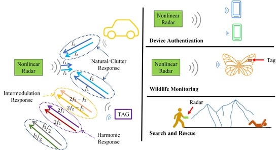
4. Harmonic Radar System
Harmonic responses are generated when a fundamental frequency tone(s) is passed through nonlinear devices such as diodes, mixers, or transistors. There has been extensive research in this area of nonlinear radars for target localization in the presence of surrounding clutter. A harmonic radar-based localization system has been commercialized by a Swedish company, RECCO, which uses this harmonic response concept for search and rescue operations. The human targets wear tagged clothing, skiing equipment, and watches, which generate a harmonic response when energized by the signal transmitted from the RECCO detector systems. The harmonic response is generated at
when a fundamental frequency
is passed through a nonlinear device. The order of the harmonic response is determined by
, where
is 2, 3, 4, etc. Most harmonic radars are based on
equals two responses as the 2nd order harmonic response has the highest power level among the harmonic responses.
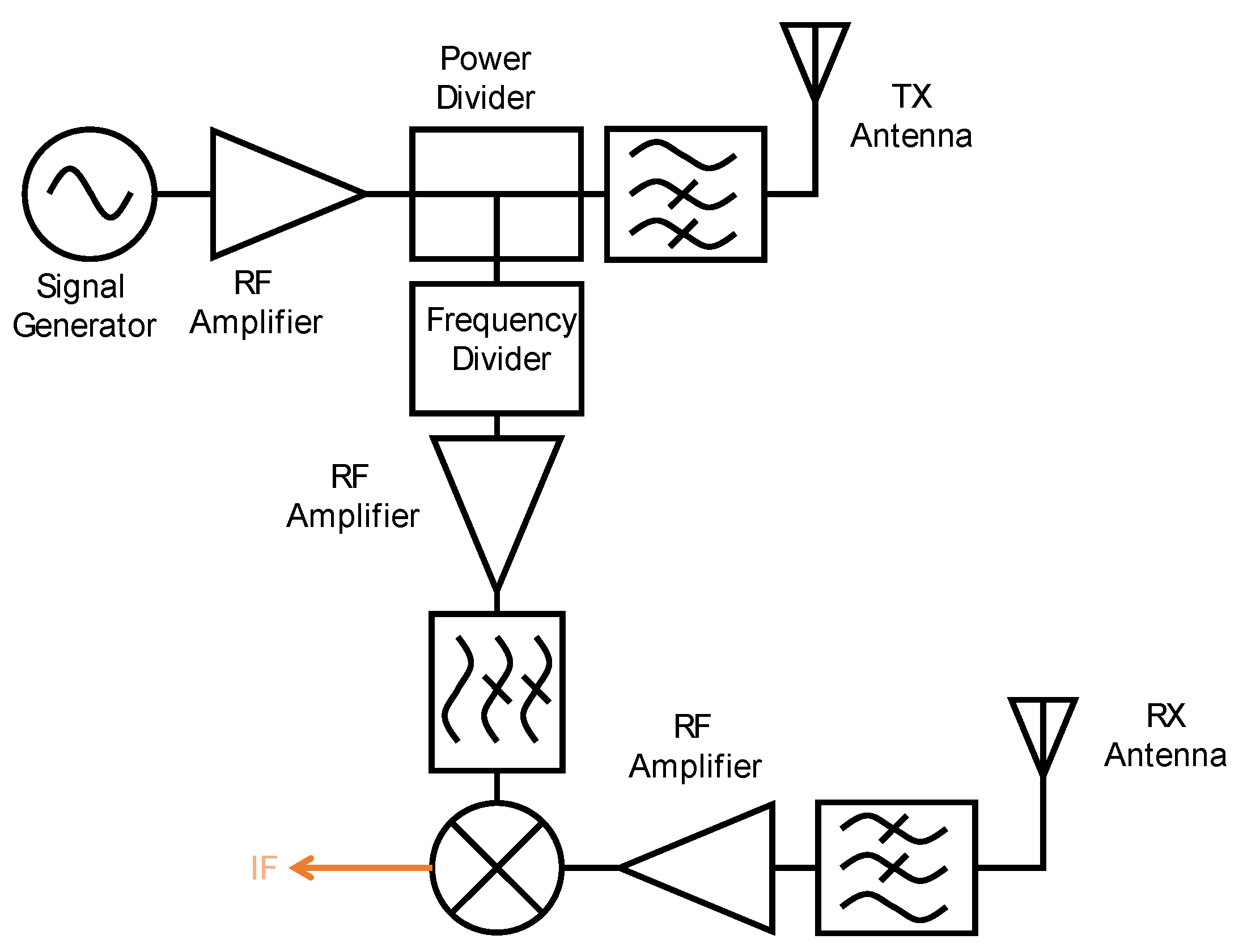
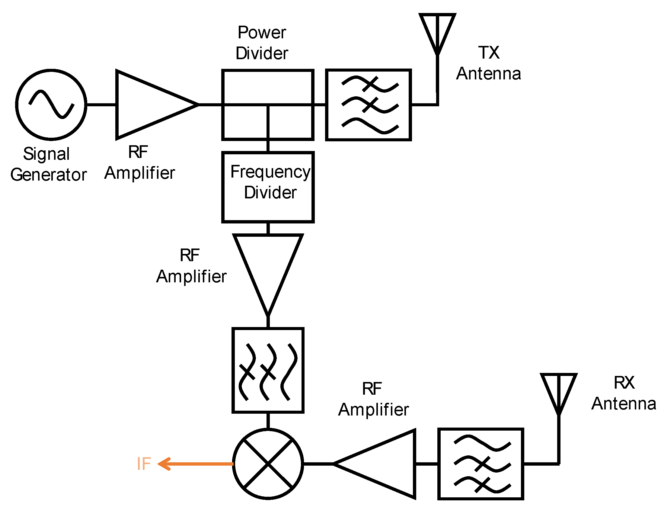
Figure 2 shows the block diagram of a harmonic radar system.
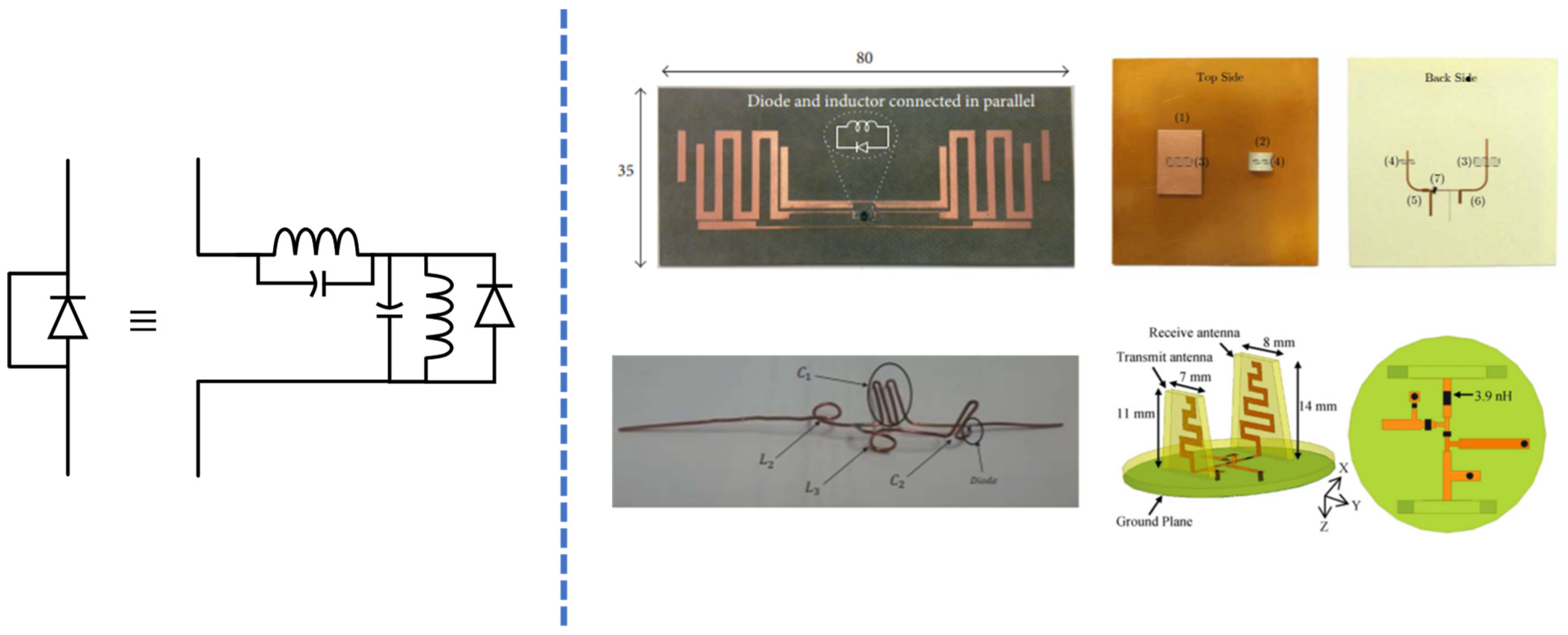
Figure 3 shows model of a passive tag with antenna and some of the backscatterer types uses with harmonic radar.
A frequency tone transmitted by the antenna is denoted as:
where 𝜙 is the phase noise of the VCO and 𝑡 is the time. The transmitted tone reaches the tag’s antenna, which absorbs this transmitted tone and sends out a series of harmonic tones and the fundamental, i.e.,
T(
t), towards the radar receiver. The nonlinear response generated by the tag is denoted as:
In Equation (10),
represents the wavelength corresponding to
,
is the mechanical displacement of the tag, and
is the nominal distance between the target and the radar. The transmitted frequency signal passes through a frequency multiplier which multiplies the transmitted frequency by
before it is fed to the
port of the mixer; hence the
port signal can be written as:
The radar receiver is tuned to the harmonic response, which is mostly 2nd order, and attenuates the other nonlinear responses and fundamental tone. The desired harmonic response is amplified and sent to the mixer for down-conversion purposes. After down-conversion, the baseband signal is obtained and forwarded to the ADCs for recording on a PC. The baseband response can be written as:
The harmonic radars are the most widely used nonlinear radar due to their straightforward design and implementation. The wide separation of fundamental and harmonic response relaxes the filter and diplexer requirement compared to the intermodulation-based nonlinear radar. Ref. [
4] discusses the relation between dipole orientation and length with the maximum detection range. The radar was designed to operate in 917/1834 MHz and used for tracking insects. Here, a study was performed discussing the effect of dipole length and bending on the dipole with the maximum detection range. Here the dipole was used as the tag’s antenna. Ref. [
5] presented the experimental and simulation-based validation of introducing an inductive loop across the diode terminals. Comparisons were performed for dipole lengths of free and fixed ends on the range, and a harmonic cross-section of the tag as a function of dipole length. In [
6], a harmonic radar operating at 5.9–6 GHz/11.8–12 GHz is discussed. A modified Minkowski loop tag was used, which provided improved harmonic conversion efficiency. The radar was able to detect insects at up to 58 m for 20 dBm output power.
In [
7], a multitone harmonic radar is discussed, which utilizes harmonic response for detecting electronic components. Ref. [
8] provides an overview of factors that should be taken into consideration when designing a harmonic radar. It discusses the impact of wavelength, radar transmission waveform, and choice of radar configuration. For example, it is noted that for tracking low flying insects, an azimuthally scanning harmonic radar is preferred over the point-and-track-based approach. Racal-Decca 90, a marine radar, was modified and utilized as a harmonic radar. Here the radar was transmitting 25 kW power with an antenna gain of 41.6 dB to track honeybees. Honeybees were tagged with a passive transponder containing a dipole antenna and a Schottky diode. Ref. [
9] discusses the use of harmonic radar for tracking butterflies in an agricultural field. The radar can track insects at a maximum distance of 1210 m with a standard error of approximately 455 m. In [
10], the authors suggested some of the improvements that can be performed in the detection efficiency of targets using harmonic radars. The range resolution of harmonic radar using pulsed radar can be improved by utilizing shorter pulses. Similarly, the frequency modulated continuous wave radar (FMCW) can improve the results by transmitting a frequency with bandwidth
, unlike the value of
for the same chirp duration. The most commonly used antenna for the harmonic transponder is dipole or monopole, which require strict orientation, i.e., they need to be stiff and straight either in a vertical or horizontal orientation to minimize the cross-polarization loss factor. These dipole or monopole antennas can be replaced with printed circuit antennas; the frequency doubler can be an externally biased energy source, such as a small piezo transducer or micro-cell, because the unbiased doubler has considerably larger conversion loss. Ref. [
11] discusses the study of tagged bees in a range of within 700 m using the harmonic radar. Their flight patterns were recorded. In [
12], the authors proposed harmonic radar with pseudorandom code (PRN code) positioning techniques; this is a spread spectrum technique for simultaneously achieving high sensitivity and accuracy. In PRN code, pulse compression is performed to accurately estimate the delay between the transmit and received signal. In comparison with other coding methods, such as Barker code and Gold code, the PRN code techniques can be generated with relatively ease and high accuracy. In [
12], the radar operated at 9.4 GHz/18.8 GHz, with a 1.75 W power level; the radar was able to detect targets at a range of up to 60 m, and with 3 kW output power, 900 m detection was expected with an accuracy of 7.5 cm.
Refs. [
13,
14,
15] discussed the use of harmonic radar for measuring the vital sign information of human targets. In [
14], the radar was operated in 12/24 GHz frequency in continuous wave (CW) mode. The measurements were performed to validate the suppression of flicker noise and improvement of signal-to-noise ratio (SNR) compared to the conventional radar operating in the fundamental and harmonic frequency region. Ref. [
15] utilized a CW-mode harmonic radar in the 2.45/4.9 GHz band. Multiple measurements were performed to validate the clutter motion rejection ability of the radar.
In [
16], a marine radar transmitting 25 kW power was used as a transmitting module for the harmonic radar. The transmitting antenna had a gain of 28.5 dBi, whereas the receiving antenna had a gain of 27.4 dBi and was connected to LNAs and power amplifiers. The radar was operated in pulsed mode and sent at a frequency of 9.41 GHz. The receiver was tuned to run at 18.82 GHz. Tags with different antenna orientation around the Schottky diode were analyzed to validate the performance of different tag types such as loop and cross across the diode. The radar was able to detect targets at a range of up to 125 m. In [
17], upgrades were undertaken to work performed in [
16], such as introducing a waveguide WR90 filter in the transmitter section to reduce the harmonics at 18.82 GHz from being transmitted, and replacing the horizontally polarized antenna with a vertically polarized antenna. The antenna gain for transmitter and receiver sections was 26.6 and 27.3 dBi, respectively. The mounting procedure and shape of the tag were further optimized. The radar was then able to detect targets at a range of up to 150 m. Ref. [
18] discusses the harmonic radar working at 9.4 GHz/18.8 GHz with 1 kW transmitting power for detecting targets at a range of up to 500 m. Compared to the previous loop or cross-shaped tag, the tag was modified into a “J” shape having arms with unequal length.
In the work in [
19], a two-tone harmonic radar design is discussed. The system had a single antenna serving the role of both transmission and receiving antennas. A low-pass filter was used in the transmitter section to attenuate any harmonics generated by the amplifiers. A high-pass filter was used in the receiver section to attenuate the fundamental response. However, in this work, the received signal was not down-converted; instead, the received signal was measured on a spectrum analyzer. In [
20], the fundamental frequency response
was swept across a wide frequency band, and the amplitude and phase of the harmonic response for each
was recorded to determine the nonlinear response of the environment. An inverse fast Fourier transform (FFT) was performed on the nonlinear frequency response to determine the target range. In this work, ranging and detection was performed on three nonlinear targets. Here, the radar was operated in a 700–900 MHz frequency region with a transmit power level of 2 W, and the ranging was performed to targets located at 12 ft. In [
21], linearization techniques for a harmonic radar are discussed. Two linearizing methods are discussed: (a) filtering and (b) feed-forward cancellation. In the filtering method, system-generated nonlinear responses are removed by either attenuating or reflecting at the output of the nonlinearity. In the case of the feed-forward cancellation circuit, the undesired signal is combined with the signal path with a phase offset to remove it. The filtering technique can be implemented in both the transmitter and receiver sections, whereas the feed-forward process is generally implemented in the transmitter section. Its implementation is not usually practical in the receiver for a moving target and clutter. Synthetic aperture radar (SAR) images of linear and nonlinear targets were measured from the harmonic and conventional radars in [
22]. The nonlinear radar was able to suppress the clutter, i.e., linear target, and detect a nonlinear target. In contrast, the conventional radar was able to pick the signature of both types of targets. Ref. [
23] discusses the filters that are used in radar. The paper discusses the change in the measured and theoretical results when low-pass filters are cascaded. Measurements were performed when the filters were connected without and with a cable. The oscillation in the stopband was more when the filters were cascaded with a cable between them. However, when the cascading was performed for the diplexers with and without a cable, the theoretical and measured values matched. This is due to the reflective behavior of the filters, which changes the
characteristic when cascaded. The receiver for a harmonic response is designed to reflect the fundamentals while allowing the harmonics to pass through. However, some of the fundamentals still leak from the RF devices. The nonlinearity presents in the RF devices, such as LNAs and amplifiers, can generate a harmonic response from the fundamental frequency and result in false alarms [
24]. Ref. [
24] utilizes states in which diplexers can be used to minimize the reflection of the unwanted frequency and thus help in improving the false alarm condition. In work [
25], harmonic radar was operated in the pulsed on-off mode, and the relation between duty cycle and power level of nonlinear response was determined for fixed incident power level. From measurements and simulations, it was found that the lowest duty cycle produces the maximum average target harmonic response. Ref. [
26] discusses the implementation of a harmonic radar transmitting a fundamental frequency from 800 to 1000 MHz and receiving harmonics at 1600–2000 MHz for imaging moving targets and obtaining SAR images of the targets in the presence of clutter. Ref. [
27] discusses the integration of harmonic radar with a Transverse Electromagnetic (TEM) cell. Here, the fundamental tone was radiated into the TEM cell containing the nonlinear target. In [
28], passive filtering is discussed. The characteristics that should be possessed by a filter to enable utilization in a harmonic radar are discussed, e.g., the passband for filters in the receiver and transmitter should not overlap; for the filter in the transmitter, the attenuation at harmonic frequency should be at least 50 dB and close to 0 dB at the fundamental. Similarly, filters in the receiver should provide more than 70 dB attenuation to fundamental, while it should be close to 0 dB for harmonics.
Harmonic radars were implemented in studying the flight behavior pattern of infected honeybees [
29]. Refs. [
30,
31,
32] discuss the use of harmonic radar to track amphibians’ behavior in a clutter-rich environment. The radar in [
30,
31] was operated in a 5.8 GHz ISM band for transmission and a 12 GHz satellite TV band for the reception for the nonlinear response.
In [
33], a harmonic radar working at 9.4/18.8 GHz could detect targets up to a range of 500 m. In the transmitter section, on-off keying (OOK) modulation and binary phase-shift keying (BPSK) were performed. Various tag topologies were tested to obtain the optimum transponder. High-gain TX and RX antennas with gains of 26.6 and 27.3 dBi, respectively, were used in this radar. To obtain high range resolution and high sensitivity, short pulses with high power were used. To receive short high-power pulses, a pulse compression technique was used. The measurements were performed in a harsh outdoor environment, and the radar was able to track targets at a range of up to 500 m. Ref. [
34] utilizes harmonic radar for tracking slow-moving targets very close to the ground. The harmonic radar was operated in the 914/1828 MHz frequency band. The antenna in the transponder was designed to match the port impedance of the Schottky diode, which was used as a nonlinear device. Bow-tie and partial bow-tie antennas were used, and the maximum detection ranges of the tags were compared.
Ref. [
35] discusses the non-linearities present on the radar sensor and the parasitic signal leakage from the transmitter to the receiver, which causes issues with tag detection. The passive tags have extremely low returns, so a weak parasitic harmonic response can negatively impact the system’s performance. This work showed that in a pulsed harmonic system, the parasitic harmonic response can be compensated and eliminated in the delay domain. With a numerical evaluation, it was proven that it can result in improved tag detection. Ref. [
36] discusses the various topologies of harmonic transponders that were designed. Based on the applications, there was some trade-off to achieve the desired characteristics using these harmonic transponders. Ref. [
37] discusses the use of harmonic radar for tracking targets that can be installed on small UAVs. The system was designed to transmit the frequency in C-band and receive the frequency in X-band. In [
38], a quasi-chipless temperature-dependent harmonic radar sensor is presented, which utilizes the response to determine the environment’s temperature at up to 3.75 m. Ref. [
39] provides theoretical and measurement validation of utilizing a two-tone signal and a dedicated receiver to overcome phase ambiguities caused by the short signal wavelength, and provided accurate localization in a multipath environment with clutter. The specific harmonic radar cross-section effect (SHRCS) concept depends on the power density of the backscatter from tags. Ref. [
40] discusses the utilization of CW radar in frequency-hopping spread spectrum (FHSS) mode. The fundamental frequency was hopped between 30 points, and a similar 30 harmonic frequency was recorded from the tag to estimate the range. Ref. [
41] discusses the use of harmonic radar in pulsed mode to estimate the distance of the target. The radar was operated in a 2.51/5.02 GHz band with a 16 dBm power level of the fundamental frequency. The matching circuit for the tag (capacitors and inductors) was realized using the wire bends. Measurements were performed for the maximum detection range as a function of the duty cycle.
Different electronic components can be distinguished from one another based on the nonlinear return signal. The nonlinear return signal strength is different for different nonlinear components; hence, based on the power level of the return harmonic signal mean, variance skewness, and kurtosis, various electronic devices were distinguished [
42]. In [
43], a series of harmonic responses from different devices were measured with respect to the change in the input power level. Fourier transform was performed on the returned harmonic responses to distinguish between different nonlinear devices.
Refs. [
44,
45] shows the implementation of a harmonic radar in the marine environment. The radar was implemented in stepped frequency continuous wave mode with an output power of ≈50 dBm in the S-/C-band. The radar was able to locate a passive target at a range of 825 m and with a 20% detection probability the radar could also detect targets at 1020 m distance. The active tags could be measured up to 5800 m with a transmit power of 100 W.
Ref. [
46] discusses the use of RECCO’s harmonic radar for obtaining SAR images from Unmanned Aerial Systems (UASs). In that work, three different steps in obtaining the SAR image were performed. In the first, the ego disturbance was calculated where the UAS was positioned at an altitude over an isolated area where external disturbances were not present. In the second step, altitude profiling was performed; here, the altitude was determined at which the radar could detect the signal with high reliability. In the third and final step, the fixed altitude response mapping was performed where the UAS was flown around an area at a constant altitude of 8 m, and a reflector placed at a height 40 cm above the ground was mapped. Harmonic radars are mainly used to track small targets that are surrounded by large clutter. These radars are used to determine the flight patterns of pests, honeybees, and other small objects. Here, the size of the transponder plays a crucial role in accurately mapping their behavior. Large and bulky transponders affect their behavior, so it is challenging to design small and light transponders which will not affect their movement pattern. Ref. [
47] discusses the design of lighter transponder tags that can generate desired harmonic frequencies with optimum power levels for ranging purposes. In [
48], a dual-channel harmonic transceiver operating at 2.4/4.8 GHz is discussed. Here the dual-channel design provides an omnidirectional interrogation capability. The harmonic repeater was enclosed in a sandy environment to validate its impact on the conversion gain and operating frequency of the radar. In [
49], a graphene-based harmonic radar transponder, for implanting in the human body, is discussed.
Ref. [
50] addresses the issue of the weak return signal from the harmonic transponder, which limits the range of harmonic radar. The most common approach to increase range is to increase the transmit power of the radar. However, the inverse sixth power dependence on the range in harmonic radar makes it an expensive approach. Here auxiliary transmission nodes are used, which results in a higher power at the receiver, thus increasing the radar’s maximum range.
The harmonic radar discussed in the above works was based on detecting the 2nd order harmonic response from the tag. In [
51], the authors designed a new harmonic radar to exploit the 3rd order harmonic response.
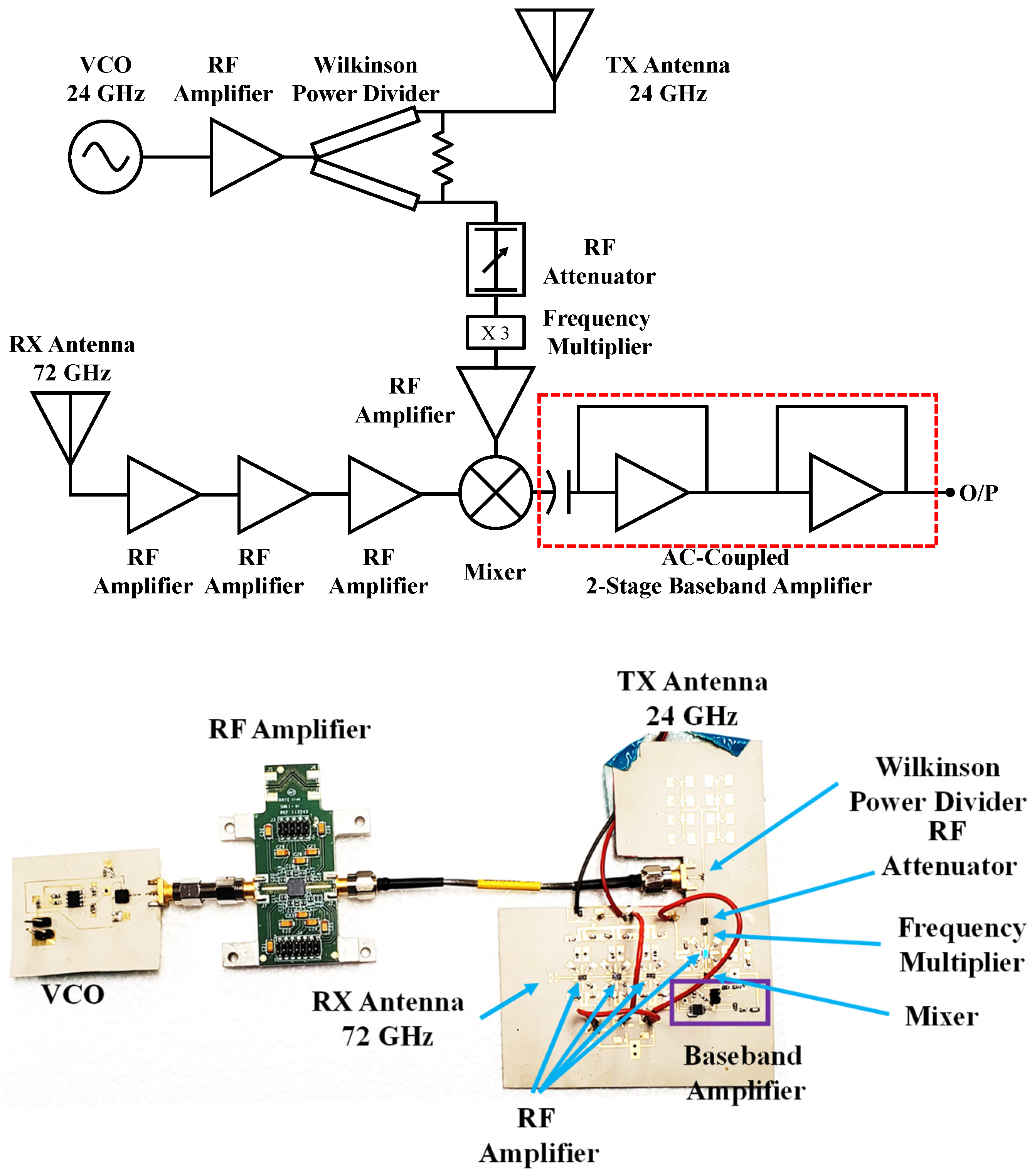
Figure 4 shows the block diagram and system of the harmonic radar operating in the 24/72 GHz band.
Figure 5 shows the passive tag that was used as a backscatterer for the radar. The 2nd order-based harmonic radar requires filters and diplexers for attenuating the 2nd harmonic in the transmitter and the fundamental in the receiver to avoid false alarms. However, because the fundamentals and the harmonics are far from one another, the devices working at the fundamental frequency band attenuate the 3rd order harmonics because the package matching does not support
. Similarly, the receiver components do not support the
frequency region.
The experimental validation of the 3rd order harmonic radar was performed with two experiments, as shown in
Figure 6. In the first experiment, tag and clutter, i.e., metal plates, were sequentially moving with equal motion amplitude and frequency. In the second experiment, the tag and clutter were moving simultaneously with unequal amplitude and frequency. The motion of the clutter was larger than the motion of the tag. The phantom shown in
Figure 6 is a mechanical device used to mimic human breathing, and the actuator is a mechanical device used to produce sinusoidal motion, where the frequency and amplitude can be programmed.
Figure 7a shows the result of the first experiment, and
Figure 7b shows the result of the second experiment. Both of these experiments shows that the radar successfully suppressed the motion of clutter.
5. Intermodulation Radar System
Harmonic and subharmonic radars have been studied extensively. They are relatively simple to design and implement. However, they suffer from issues such as licensing because the fundamental and harmonic/subharmonic responses lie in different frequency bands. Thus, the nonlinear tags require a matching circuit for optimum operation, and the harmonic tags therefore need matching for two bands, i.e., fundamental and harmonic. As a result, the matching circuit for harmonic radars is more complex compared to intermodulation-based tags where fundamental and desired nonlinear responses lie in the same band; thus, the matching circuit needs to be designed for narrowband operation.
When two or more frequency tones are passed through a nonlinear device, the device produces additional frequency tones in addition to fundamentals and harmonics. These additional tones are called intermodulation. The discussion here is limited to odd-order intermodulation products. These intermodulation products are produced at
, where
and
are the two fundamental tones illuminating the nonlinear device. The order of the intermodulation is
.
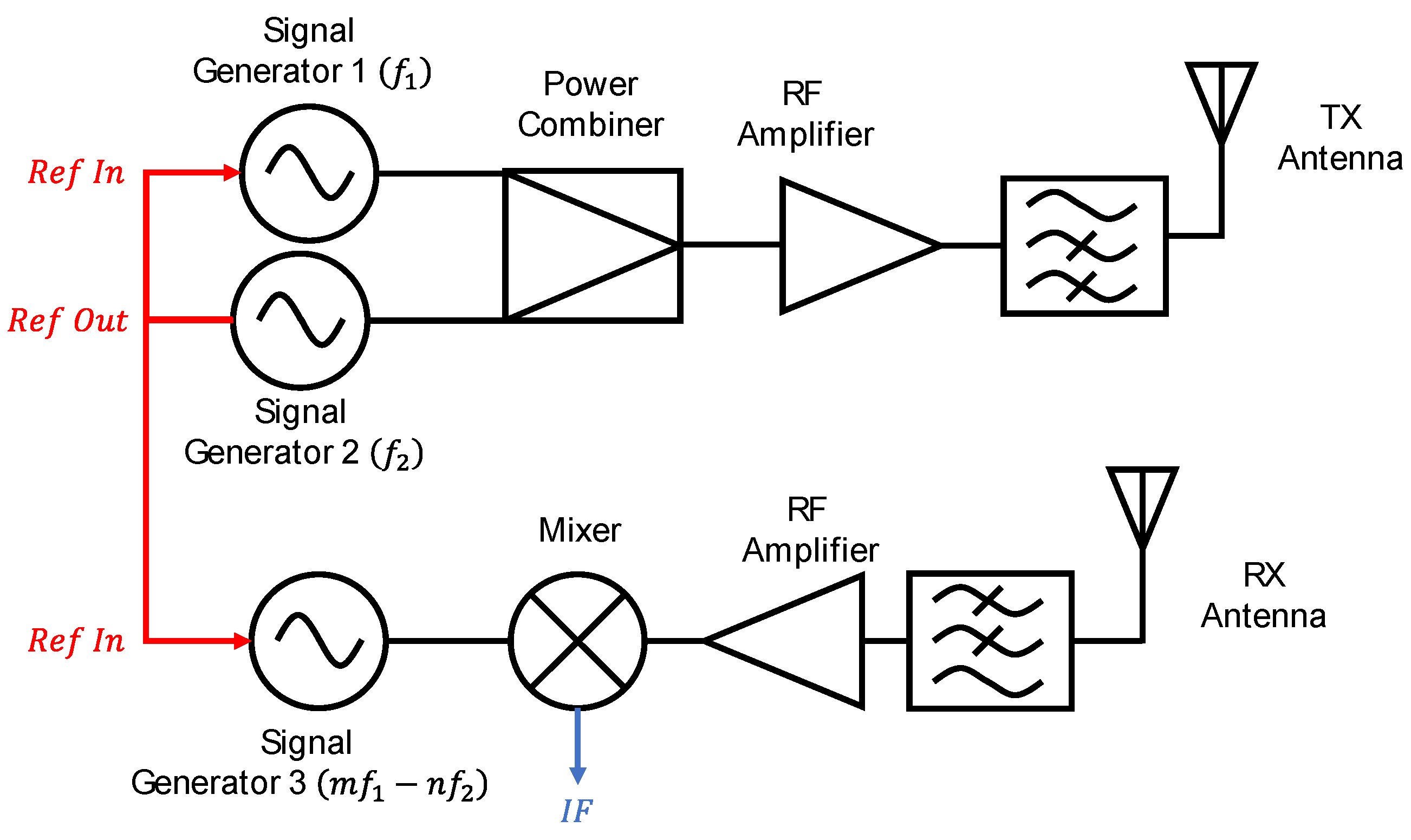
Figure 8 shows the block diagram of an intermodulation radar. Here, three signal generators are generally utilized: two signal generators to generate fundamental frequency tones
and
for transmitting into the environment, and a third signal generator at
for down-converting the received tones to extract Doppler or range information of the nonlinear target. Generally, the third signal generator is tuned to 2
or
as these frequency tones have the highest power levels among the nonlinear response within the same band.
The antenna transmits two or more frequency tones, denoted as:
where
is the phase noise of the
signal generators, and 𝑡 is the time. The transmitted tone reaches the tag’s antenna, which absorbs this transmitted tone and sends out a series of intermodulation tones along with the fundamentals. The nonlinear response generated by the tag is denoted as:
In Equation (14),
represents the wavelength corresponding to
intermodulation frequency,
is the mechanical displacement of the tag, and
is the nominal distance between the target and radar. The transmitted frequency signal passes through a frequency multiplier which multiplies the transmitted frequency by
before it is fed to the
port of the mixer; hence the
port signal can be written as:
The radar receiver is tuned to intermodulation response, which is mostly 3rd order, and attenuates the other nonlinear responses and fundamental tone. The desired intermodulation response is amplified and sent to the mixer for down-conversion purposes. After down-conversion, the baseband signal is obtained, and sent to the ADCs for recording on a PC. The baseband response can be written as:
Here,
is the residual phase noise and can be ignored for short distance approximation due to the range correlation effect [
52].
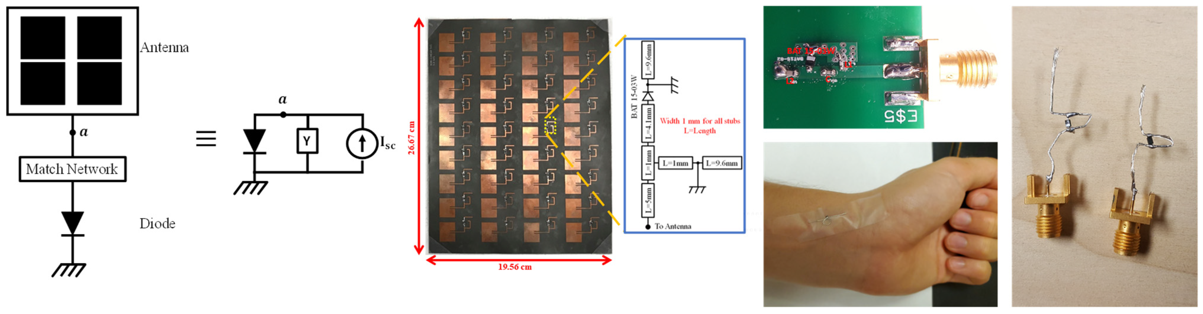
Figure 9 shows the model of a passive diode-based tag and some of the tags utilized for this radar for ranging and motion detection in the presence of clutter.
Intermodulation-based radar has gained interest for its utilization in clutter rejection purposes. In [
53], a contactless method of determining the radiation pattern of a transponder is discussed. In [
54], an antenna working at a 77 GHz automotive band was designed to be used with an intermodulation radar. A simulation was performed to validate the target discrimination with an intermodulation radar. An RFID-based system based on intermodulation response is discussed in [
55]. Two tones were illuminated on the active tag, and backscatter from the tag was recorded. The RFID reader transmits frequencies at 2.4 and 2.46 GHz, and utilizes a 2.34 GHz return signal for validation.
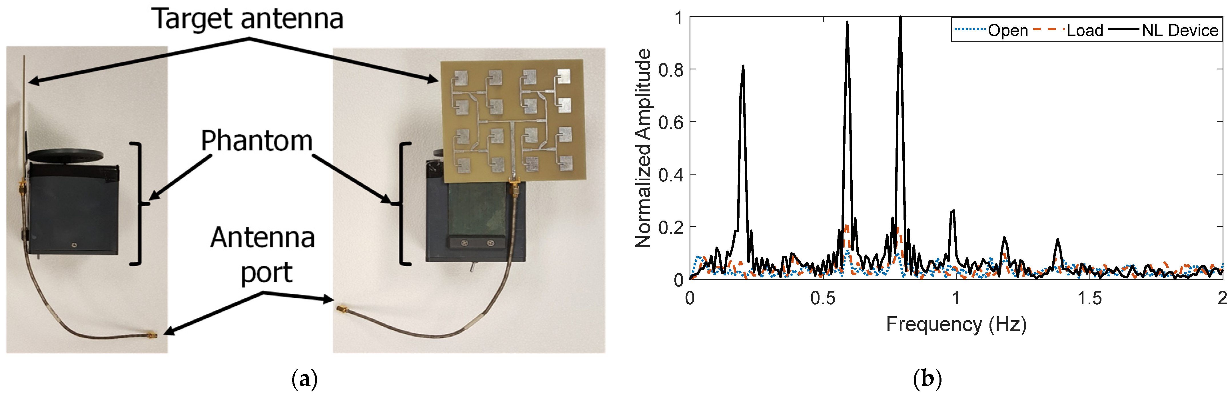
In [
56], for the first time, the intermodulation response was utilized for remote sensing of motion of clutter and a target. In this work, the intermodulation radar was designed and operated in a 5.8 GHz ISM band, and experimental validations were performed to determine the clutter rejection ability of the radar. A four-by-four antenna array was mounted on the phantom, and a long SMA cable was connected to it. The antenna array and phantom were made to move back and forth in front of the radar under three conditions when the SMA port was: open, connected to a
load, and connected to the nonlinear device. The motion under the three conditions was recorded.
Figure 10a shows the antenna’s connection with the phantom, and the measurement result is plotted in
Figure 10b. It can be seen from the measurement result that the motion frequency of the phantom could be recorded only then the antenna was connected with the nonlinear device, whereas in the case of open and load conditions, the measurement frequency could not be recorded.
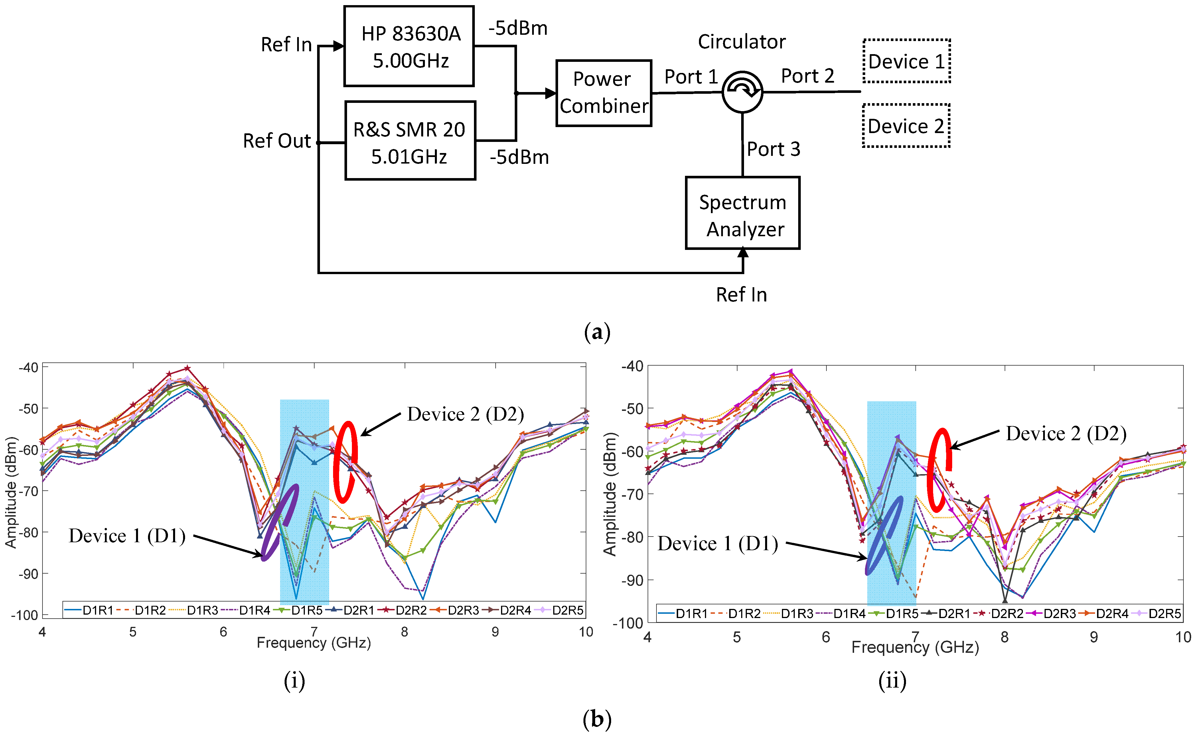
The intermodulation responses were utilized in authenticating two similar devices having identical components and matching circuits. In work [
57], the intermodulation return signal from the nonlinear device was recorded.
Figure 11 shows the measurement setup for transmitting the fundamental response to the nonlinear targets and recording their fundamental and intermodulation return. Two signal generators were used to transmit the two frequency tones towards the power combiner, and the output of the power combiner was sent towards the circulator. The circulator was connected to send signals from Port 1 to Port 2 and Port 2 to Port 3. Thus, the nonlinear devices were connected sequentially to Port 2 and the return signal from these devices was recorded on a spectrum analyzer connected to Port 3. The fundamental return signals, when used for authenticating these two devices, have a minimal difference in power level. Thus, they were discarded; however, when the 3rd order nonlinear responses were utilized for differentiating these two devices, the power level trend showed a similar trend for most of the frequencies. At a particular frequency band, the difference in power level was significant. In this work, a power level difference of more than 10 dB was considered to be significant.
Figure 11b shows the nonlinear return signal from the two devices from 4 to 10 GHz, with
as 10 MHz and a step size of 100 MHz. The power level was set as 5 dBm at 5 GHz for both tones.
In [
56], the intermodulation-based radar was first designed, the motion frequency was recorded, and clutter rejection was first performed. However, in [
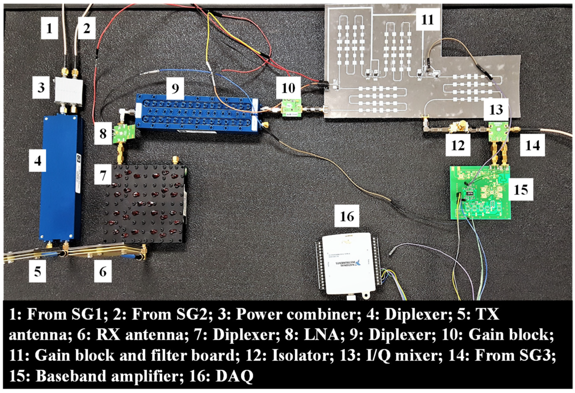
56], due to the absence of a series of LNA and RF amplifiers, the radar’s sensitivity was very low. This had an impact on the maximum distance and minimum motion amplitude the radar could measure, without linearizing the transmitter and section, and utilizing amplifiers and LNAs to boost the transmitted and received signal. As a result, the intermodulation radar was modified, and a series of amplifiers and LNAs were connected while maintaining or even improving the linearity of the radar system. The sensitivity was improved from −65 to −120 dBm.
Figure 12 shows the system diagram of the 5.8 GHz ISM band intermodulation radar. Because the intermodulation radar required attenuating the unwanted tomes within the same band, off-the-shelf filters could not be utilized since the roll-off feature needs to be very sharp. Thus, either custom filters have to be used, or diplexers are required. Filters need to be reflectionless because connecting two or more reflection-based filters does not provide the desired attenuation as theoretically calculated based on
, and the reflection of the tones tends to alter the behavior of the filter. Hence, diplexers are preferred as the unwanted frequency is directed to a different path where a
load is connected which absorbs it instead of reflecting it to the previous stage. Moreover, the diplexers provide a very steep roll-off. Hence, in [
58,
59], diplexers were utilized to attenuate any unwanted tones absorbed by the antenna or generated by the nonlinear components to provide the desired linearity and avoid false alarms. The radar was used to measure the vital signs of a human target. The goal of the experiment was to measure a stronger heartbeat pattern compared to respiration. In the case of the conventional radars, the breathing pattern is stronger compared to the heartbeat pattern because displacement of the lungs during the respiration process is much larger than the displacement of the heart during a heartbeat. Hence the harmonics of respiration peaks in the frequency spectrum overlap with the weaker heartbeat peaks and lead to loss of information. Thus, by making the respiration weaker than the heartbeat, the information is not lost. The validity of the heartbeat signal was compared with reference data.
Figure 13a shows the placement of the tag on the human target. Here, the tag was aligned to the heart location to record a stronger heartbeat pattern.
Figure 13b shows a short-time Fourier (STFT) plot obtained from the radar data. It can be seen that the radar successfully recorded a stronger heartbeat pattern compared to respiration.
In [
58,
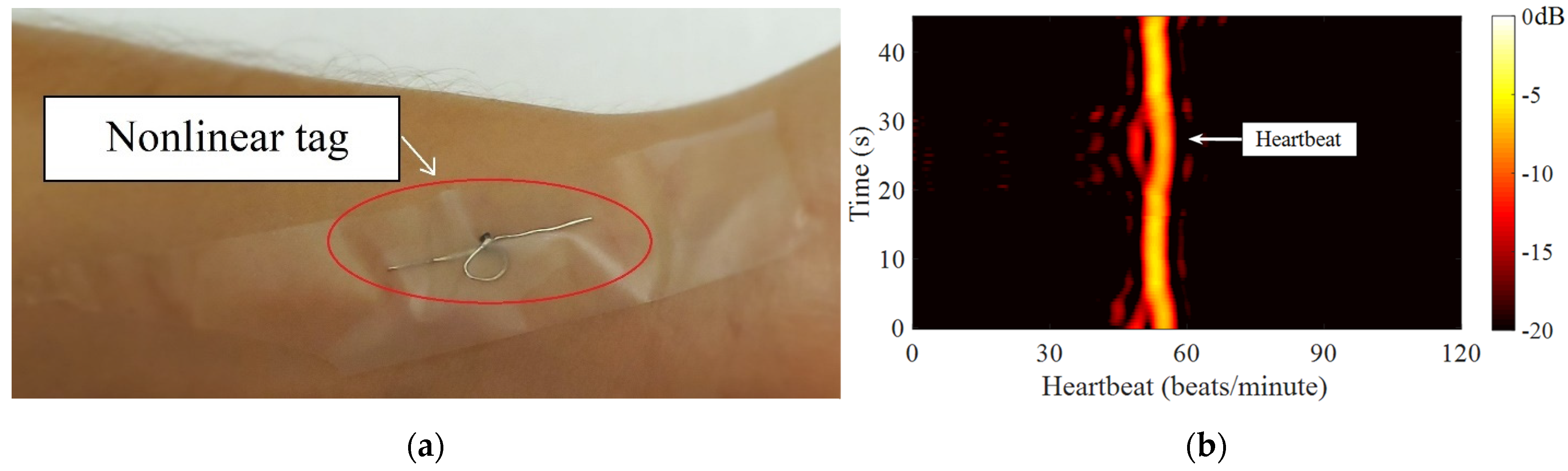
59], a thirty-six-element tag was used to record the strongest heartbeat pattern. However, this thirty-six-element tag is not practical to be utilized in all scenarios. Thus, a smaller tag was designed by placing a dipole antenna across the diode’s terminals and a wire loop connecting both the diode’s ends for biasing purposes [
60,
61]. The tag was placed on the wrist aligned to the radial artery.
Figure 14a shows the placement of the tag on the wrist for measuring the heartbeat. The wrist was placed in front of the radar in the near-field region to measure the heartbeat pattern.
Figure 14b shows the spectrogram obtained when the tag was placed on the wrist and kept in the near-field region. The plot shows a strong heartbeat pattern. In [
62], vital signs of the human target under different postures were recorded, such as sleeping, sitting with the wrist touching the torso, and sitting with the wrist not touching the torso. The radar was able to detect vital signs, especially heartbeat patterns, in all these scenarios. Error analysis was also performed on the heartbeat data recorded by the radar compared to the reference. It can be seen that the error was <
under all the measurement scenarios.
In the above works [
53,
54,
55,
56,
57,
58,
59,
60] on intermodulation-based nonlinear radars, only motion frequency could be obtained, and the radars could not be utilized for ranging purposes. In [
61], the intermodulation radar was operated in frequency-shift-keying (FSK) mode. In this mode,
of the tone was kept constant while
of the tone was switched between two frequencies
; thus, corresponding to the switching of
, the lower 3rd order tone was generated at two frequencies, i.e.,
and
. A tag was placed on the target, so the tag backscattered the intermodulation response added with Doppler based on the incident fundamental tones. The radar sensor down-converts the received intermodulation response with a copy of the 3rd order tone at the
mixer.
An FFT is performed on this down-converted signal, and the Doppler frequency peak of the target is identified for
and
return signals. The phase information is calculated from the FFT spectrum and the range of the target from the radar is determined using:
where
is the velocity of electromagnetic wave,
is the phase difference of the returned signal, and
is the
.
Figure 15a shows the experiment setup where the range of the human target was determined based on the FSK modulation scheme. Unlike in previous intermodulation radars, where at least three signal generators with shared reference to maintaining coherence were utilized for operation, in [
61], two signal generators were used. An external reference for maintaining the coherence was discarded; instead, a diode maintained the coherence between the fundamental and nonlinear response.
Figure 15b shows the range measurement of a target for a 70 s duration.
In [
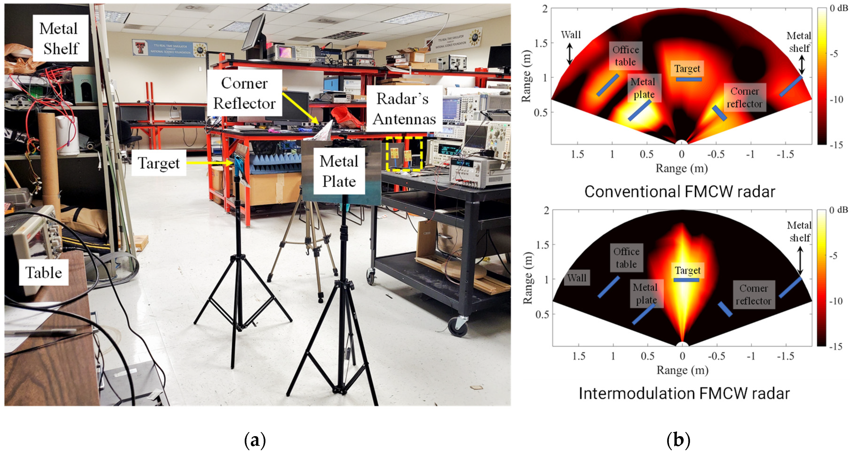
62], the intermodulation radar was operated in frequency-modulated continuous-wave (FMCW) mode. Similar to FSK mode, one of the fundamental tones was swept with a bandwidth, which resulted in the generation of a 3rd order response to be generated with the same bandwidth in the opposite direction.
Figure 16 shows the modulation scheme of the intermodulation response when one of the fundamental tones is swept. The radar was used for mapping targets in a clutter-rich environment, as shown in
Figure 17a. The measurement obtained by this radar was compared with the state-of-the-art conventional FMCW radar, and the mapping result is plotted in
Figure 17b. As shown in the figure, it can be seen that a conventional radar cannot discriminate between clutter and target. It records the location of all the objects present in its vicinity, whereas an intermodulation radar was successfully able to suppress the clutter response and record the location of the target.
For suppressing the unwanted response, generally, diplexers and filters are used. This makes the system expensive and bulky. Thus, in [
63], a frequency cancellation technique to remove unwanted responses is discussed. This technique can be used to replace the filters and diplexers in the system, making the whole architecture portable and cheap. The unwanted tones can be canceled by more than 60 dB when a perfect phase matches the undesirable and cancellation tones.


