Communication

P-Band InSAR for Geohazard Detection over Forested Terrains: Preliminary Results

Roy M. Huffington Department of Earth Sciences, Southern Methodist University, Dallas, TX 75205, USA
*
Author to whom correspondence should be addressed.
Remote Sens. 2021, 13(22), 4575; https://doi.org/10.3390/rs13224575
Submission received: 12 October 2021 / Revised: 11 November 2021 / Accepted: 11 November 2021 / Published: 14 November 2021
(This article belongs to the Special Issue Advances in InSAR Imaging and Data Processing)

Abstract

:
Decorrelation of X, C, and L-band InSAR (Interferometric Synthetic Aperture Radar) over densely vegetated regions is a common obstacle for detecting ground deformation beneath forest canopies. Using long-wavelength P-band SAR sensors (wavelength of 69.72 cm), which can penetrate through dense forests and collect relatively consistent signals from ground surface, is one potential solution. Here, we experimented using the NASA JPL (Jet Propulsion Laboratory)’s P-band AirMOSS (Airborne Microwave Observatory of Subcanopy and Subsurface) radar system to collect repeat-pass P-band SAR data over densely vegetated regions in Oregon and California (USA), and generated by far the first P-band InSAR results to test the capability of P-band InSAR for geohazard detection over forested terrains. Our results show that the AirMOSS P-band InSAR could retain coherence two times as high as the L-band satellite ALOS-2 (Advanced Land Observing Satellite-2) data, and was significantly more effective in discovering localized geohazards that were unseen by the ALOS-2 interferograms over densely vegetated areas. Our results suggest that the airborne P-band InSAR could be a revolutionary tool for studying geohazards under dense forest canopies.

1. Introduction

Radar remote sensing is an effective and efficient method for mapping and monitoring geohazards such as earthquakes, volcanoes, urban subsidence, and landslides (e.g., [1,2]). Successful applications of X-, C-, and L-band InSAR (wavelengths of 3.1, 5.6, and 24.2 cm, respectively) for ground deformation detection and measurement have been demonstrated all over the globe since the 1990s [3]. However, over densely forested terrains, radars’ capacity of detecting geohazards beneath tree canopies could be compromised, depending on the wavelength of radar waves. Short-wavelength (X/C-band) radar pulses may not be able to penetrate through the dense forests, and therefore the backscattered signals from vegetation canopy instead of the ground surface often lead to strong decorrelation in repeat-pass SAR acquisitions, and render the data ineffective for geohazard detection (e.g., [4,5]).
Using a longer-wavelength (L/P-band) sensor is one of the potential solutions to strengthen radar’s capability for geohazard detection over forested terrains. Based on this rationale, we experimented on acquiring repeat-pass P-band SAR (wavelength of 69.72 cm) data using the NASA/JPL AirMOSS system over multiple forested areas in Oregon and California, and assessed the interferometric capability in detecting localized ground deformation in these regions. The single-pass P-band data have been collected in several areas of interest around the world for biomass estimation and soil moisture studies (e.g., [6,7]); however, our experiment is by far the first to collect repeat-pass P-band SAR data and generate InSAR results in order to detect localized geohazards over forested terrains.

2. Data and Methodology

2.1. Airborne P-Band SAR Acquisition and Processing

For this experiment, we utilized the NASA/JPL AirMOSS radar system [8] to acquire repeat-pass P-band data for three vegetated regions in Oregon and California (USA) (Figure 1). The three targeted regions were annotated as GB (Gold Beach), SB (Somes Bar), and HC (Happy Camp), respectively, based on local toponyms. The first and second data acquisitions were obtained on 8 December 2020, and 5 May 2021, respectively (Table 1). The NASA/JPL AirMOSS system was mounted on a Gulfstream C-20A (GIII) aircraft and was equipped with a left-looking P-band radar sensor (wavelength of 69.72 cm) to acquire 12-km wide stripmap data along the flying path. The location and motion of the AirMOSS system were provided by the high-precision inertial navigation unit (INU) and differential global positioning satellite subsystem (DGPS), with real-time correction updates via the Iridium satellite phone [8]. The radar view angles vary from approximately 25° at the near range to 65° at the far range, which correspond to an incidence angle of about 45° near the middle range. The heading angles of SAR acquisitions for the three target regions vary, which are depicted in Figure 1, and detailed in Table 1.
Pixel spacings for the collected P-band SLC (Single Look Complex) data measured 1.7 by 0.6 m (range by azimuth), and multi-looking factors of 3 by 12 pixels (range by azimuth) were used to generate multi-looked, HH-polarized images. To form interferograms, the relative aircraft motion between the two data takes was compensated based on DGPS/INU data [10] plus aircraft motion correction, which was estimated from subpixel-level matching of the two processed SAR SLC images [11]. After the employed motion compensation during image formation, the spatial baseline of each pixel between two acquisitions approximated zero. Consequently, the topographic contributions to the InSAR phase were automatically removed during the interferogram generation. The 1-arcsec SRTM DEMs (Shuttle Radar Topography Mission—Digital Elevation Models [12]) were used to geocode the P-band SAR products. Phase unwrapping of the wrapped SAR interferograms was achieved using the ICU (integrated correlation and unwrapping) method [13]. In addition, we implemented differencing of the P-band SAR intensity data to map geohazards that caused substantial changes of surface scatterers, and were often undetectable by the InSAR technique due to severe coherence loss.

2.2. Spaceborne L-Band SAR Acquisition and Processing

To compare the capability of the P-band and L-band SAR data for geohazard detection, we also obtained the spaceborne L-band ALOS-2 PALSAR-2 (Phased Array type L-band SAR-2) data that covered the three target regions. The target region, GB, was covered by the descending-track ALOS-2 data, which were acquired on 23 May 2020 and 22 May 2021. The regions SB and HC, were covered by the descending-track ALOS-2 acquisitions on 11 April 2020 and 10 April 2021 (Figure 1). The ALOS-2 data shared a similar heading angle of −169° and an incidence angle of approximately 34° throughout the three target regions. Pixel spacings of the ALOS-2 SLC data measured approximately 4.3 by 3.5 m (range by azimuth), and multi-looking factors of 2 by 1 pixels (range by azimuth) were used to match the pixel spacings of the multi-looked AirMOSS P-band data (Table 1). The 1-arcsec SRTM DEMs were utilized to minimize the topographical contributions to the SAR phases and to geocode the SAR images. The orbit-related artifacts were reduced using quadratic fitting, and the topography-related stratified atmospheric artifacts were reduced by using linear fitting. We used the GAMMA software [14] to generate the SAR interferograms, and employed the minimum cost flow approach to achieve unwrapping by setting a coherence threshold of 0.2. The coherence threshold was determined from the measured coherences over large waterbodies on the SAR interferograms.

3. Results

3.1. Identified Geohazards from P-Band InSAR

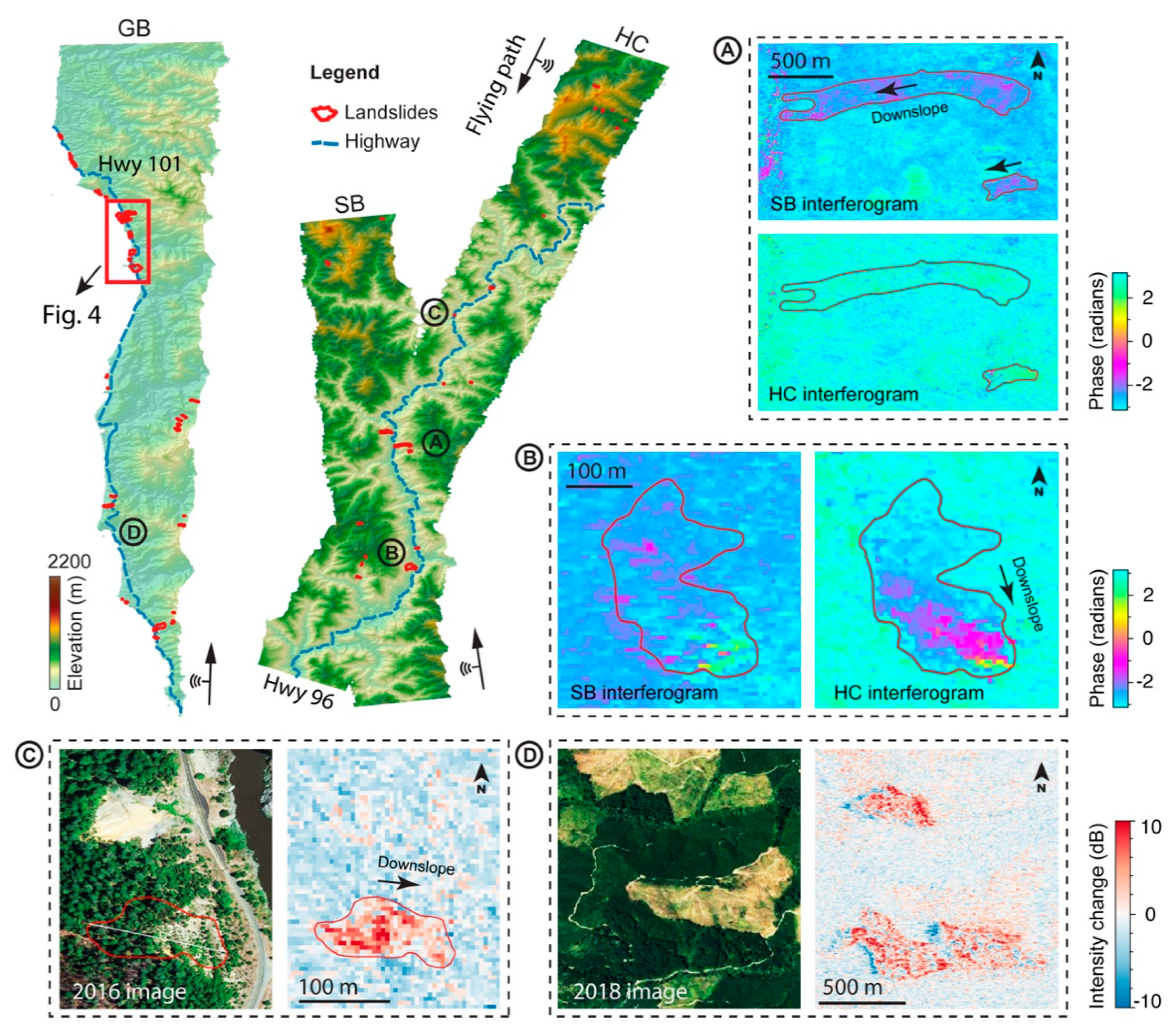
Using the interferograms generated from the P-band AirMOSS data acquired in December 2020 and May 2021 over the three target regions (i.e., GB, SB, and HC), we identified 55 landslides which were actively moving during the observation period (Figure 2). Of these landslides, 39 were not included in the national landslide inventory, which is a compilation of currently existing, non-systematically mapped global, national, and regional-level landslide inventories [15]. Comparison with the ALOS and ALOS-2 mapped active landslides between 2007 and 2019 [16] showed that the P-band InSAR revealed 40 new landslides, particularly the relatively small-sized ones (less than 4 × 10⁴ m2). However, the P-band data from December 2020 to May 2021 did not capture motions of 12 landslides that were reported active between 2007 and 2019 using L-band satellite InSAR observations [16]. Potentially, the undetected landslides were due to their inactivity during the P-band SAR acquisitions, or their motions were extremely slow enough to be unidentifiable to the long-wavelength P-band SAR interferogram.
Spatial sizes of the identified landslides range from 4.4 × 10³ to 7.2 × 10⁵ m2. Among these landslides, 12 intersect with the Highway 101 along the southern Oregon coastline, and 4 intersect the Highway 96 along the Klamath River in the northwestern California. The movement of these landslides often slowly and constantly damages the highway by displacing the roadbed and causing cracks [17]. The measured maximum line of sight (LOS) displacement of the identified landslides was 0.57 m during the observation period, which corresponded to a LOS deformation rate of 1.3 m/yr.
The look directions of the radar sensors largely affect their sensitivity for detecting geohazards, depending on the dominant orientation of the to-be-detected ground displacement. The highest sensitivity generally lies along the LOS direction of the radar sensor, and gradually decreases towards the LOS-perpendicular direction. As exemplified by the two landslides in Figure 2, motion signals of the east-west oriented landslide (Figure 2A) were apparent in the approximately west-looking “SB” acquisitions, but such movement signals were hardly recognizable from the southeast-looking “HC” interferogram. In contrast, the northwest-southeast orientated landslide (Figure 2B) was more clearly detected by “HC” rather than the “SB” interferograms.
Significant alterations of surface scatterers caused by landslide runout (Figure 2C) or clear cuts (Figure 2D) usually lead to substantial changes in SAR intensity, which can therefore be used to detect certain types of geohazards. However, additional information, such as local topography and high-resolution optical images, may be needed to help discriminate the causes of the SAR intensity change. For example, both landslide runout and clear cut may alter SAR intensity by up to 10 dB (Figure 2C,D), but landslide failures are less likely to occur on flat terrains based on empirical knowledge. Consequently, extra information from topographical maps and optical imagery can help to interpret that the intensity change in Figure 2C was caused by landslide activity, whereas that presented in Figure 2D was by clear cutting.

3.2. Coherence Comparison of P-Band and L-Band InSAR

To compare the quality of the SAR interferograms generated from the repeat-pass P-band AirMOSS and the L-band ALOS-2 acquisitions, we utilized the InSAR coherence as an index for the analysis. InSAR coherence ranges from 0 to 1, and a higher coherence in general indicates a lower level of background noise, and therefore more reliable InSAR measurements (e.g., [18]). A moving window of 3 by 12 pixels (range by azimuth) was applied to both the P-band and L-band data for the coherence estimations.
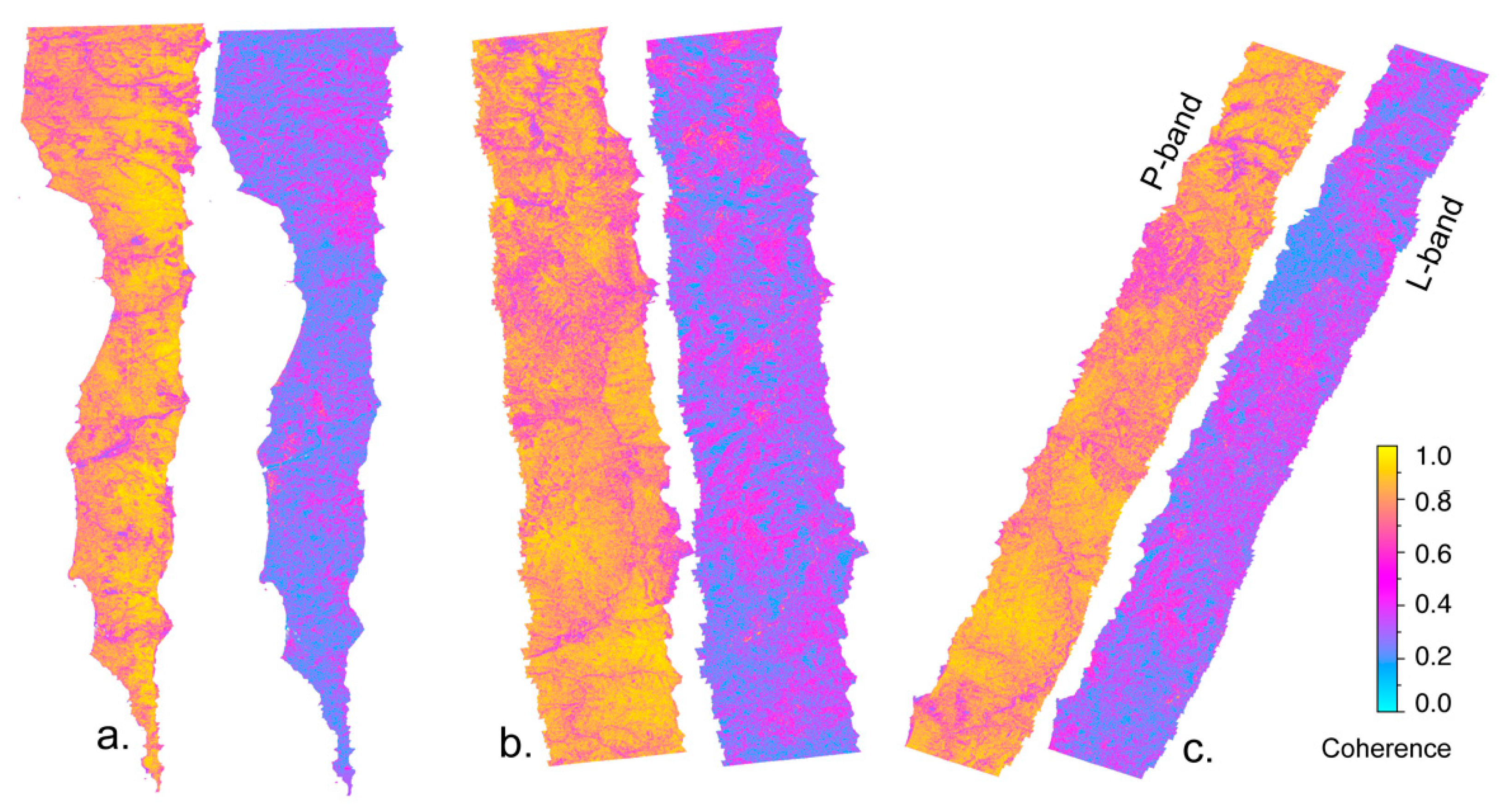
As shown in Figure 3, the P-band AirMOSS acquisitions demonstrated higher coherences than the L-band ALOS-2 imagery over all three target regions. The average coherences of the P-band InSAR for the GB, SB, HC regions were 0.78, 0.77, and 0.77, respectively, with a similar standard deviation of approximately 0.17. In contrast, the average coherences of the L-band InSAR for the three regions were 0.30, 0.35, and 0.34 respectively, with a similar standard deviation of 0.16. Overall, the P-band data had an average coherence that was 2.3 times as high as the L-band acquisitions for these vegetated regions.
Note that the two P-band acquisitions were acquired in different months, with one in December and one in May, whereas the L-band images were collected in the same month of different years. The study region is in the Mediterranean climate zone, where the wet season approximately spans from October to April, and the dry season from May to September. Due to the impacts of seasonal variations in surface soil moisture and vegetation growth, SAR data acquired in the same season can generally maintain higher coherence with other factors being equal (e.g., [16]). Consequently, even better coherence can be expected for the P-band data if they were collected in the same season as the L-band SAR acquisitions.
A detailed inspection revealed that water bodies, river channels, clear cuts, and vegetation regrowth after clear-cutting were the primary causes for significant coherence loss for both the P-band and L-band SAR acquisitions (Figure 3). On the contrary, regions with sparse and shallow vegetation generally maintained high coherence for both the P-band and L-band SAR interferograms. Stream channels covered by dense forests are often hardly recognizable from high-resolution optical images; however, they are more clearly distinguishable from P-band SAR coherence maps, where they appear as the linear features with very low coherence. The P-band SAR sensors are capable of penetrating through dense forests to image the stream surfaces, which are often captured as low-coherence areas because their backscattered signals vary by different acquisition times.

3.3. Comparison of P-Band and L-Band SAR on Geohazard Detection

Successful identification of ground deformation from SAR interferograms largely relies on the relative magnitude of the deformation signal and the background noise. The uncertainties of the InSAR measurements, σ, can be quantified as [19]:
σ = λ 4 π 1 2 L 1 γ 2 γ 2
where λ is the wavelength of the radar wave, γ is the estimated InSAR coherence, and L is the window size used for the coherence estimation. In this study, we utilized a window size of 36 pixels to estimate the InSAR coherences, and set the coherence thresholds of 0.4 and 0.2 to unwrap the P-band and L-band interferograms, respectively. The estimated minimum measurement accuracies were 0.98 cm for the P-band InSAR, and 0.91 cm for the L-band InSAR, therefore.
Here, we highlighted an exemplary region in the southern Oregon coast to compare the quality of P-band and L-band InSAR for geohazard detection. As illustrated in Figure 4, the airborne P-band InSAR provided much clearer results for identifying localized ground deformation than the satellite L-band ALOS-2 InSAR. On the wrapped interferograms, P-band data showed a much lower level of background noises than the L-band data due to the significantly higher coherence (see Equation (1)), which is critical for determining spatial boundary of the deforming region (Figure 4). The nine active landslides were clearly identifiable on the P-band SAR interferogram, whereas they were surrounded by strong background noises and barely recognizable on the L-band interferogram (Figure 4a,d). As illustrated in Figure 4b,e, the landslide regions had coherences greater than 0.4 for the P-band data, yet below 0.3 for the L-band data. On the unwrapped interferograms, the P-band results again revealed more clear deformation signals than the L-band results, though some landslides were also slightly discernible on the L-band interferogram. Due to the higher coherences, the P-band InSAR was able to provide reliable displacement measurements for most parts of the landslides (see Equation (1)). In contrast, the L-band InSAR could only provide much fewer reliable measurement points. Note that the unreliable measurement points were masked out in Figure 4c,f by using a coherence threshold of 0.2. The low-coherence regions within the identified landslides on the unwrapped P-band interferograms were mostly likely caused by large landslide movements.

4. Discussion

4.1. Impacts of Radar Frequency Bands

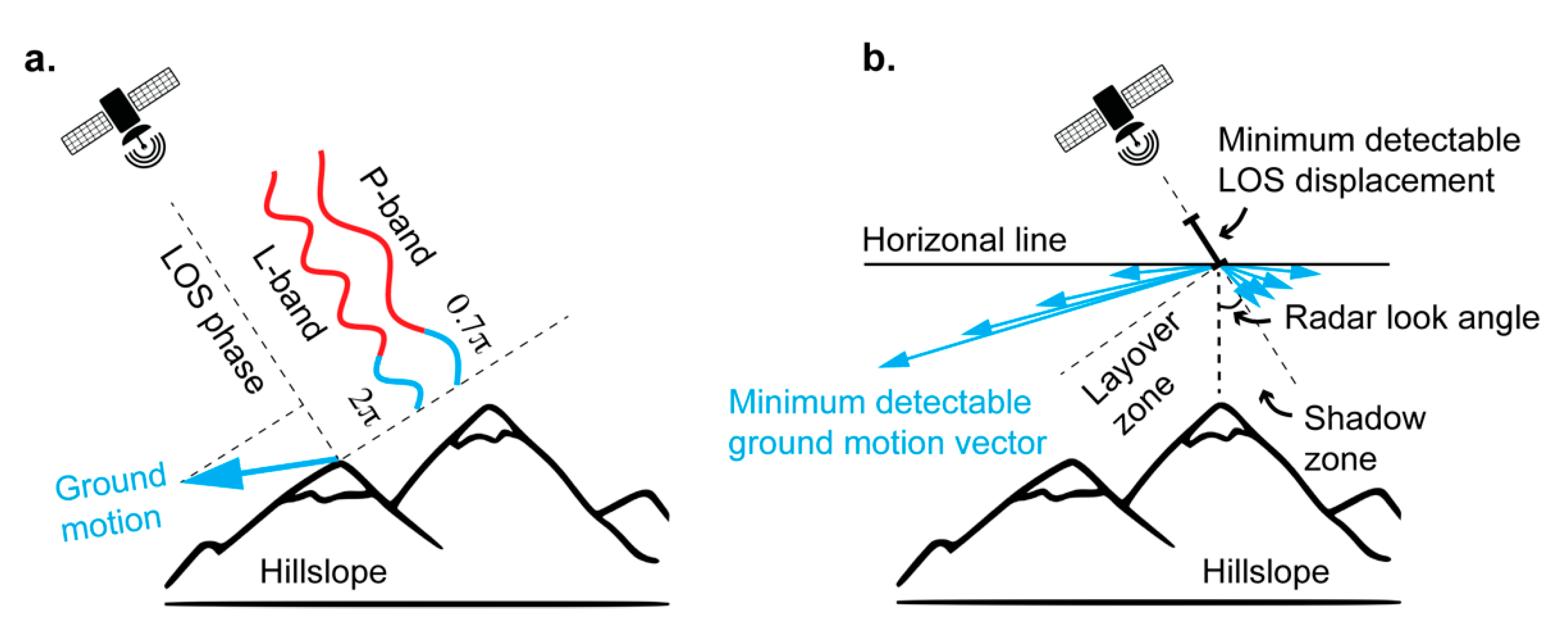
The employed radar frequency bands of SAR systems largely affect their effective width of data swath, the pixel resolution along the range direction, the ground and vegetation penetration depth, and the sensitivity for ground deformation detection. The latter three factors are critical for detecting localized geohazards over vegetated terrains. Higher pixel resolution is beneficial for identifying small-sized geohazards, which only occupy a few pixels on coarse resolution images, and therefore may be undistinguishable from random noises. Long-wavelength SAR systems perform much better in terms of vegetation penetration depth [20], which is crucial for mapping geohazards under dense forest canopies. Fundamentally, the radar waves must reach the ground surface rather than the swinging tree branches to maintain relatively stable backscattered signal, and thus better coherence. However, long-wavelength radars are less sensitive to detecting small deformation (see Equation (1)), since InSAR measures phase changes are caused by ground deformation. For example, a LOS displacement of 24.24 cm would lead to a phase change of 2π on the L-band ALOS-2 interferograms, but it only corresponds to a 0.7π phase change on the P-band AirMOSS interferograms (e.g., Figure 5a). In general, for detecting geohazards with large deformation (e.g., landslides) over forested terrains, the importance of vegetation penetration outweighs that of the phase detection sensitivity, so longer-wavelength SAR systems are preferred. By contrast, for detecting geohazards with small deformation over bare terrains (e.g., volcanoes and urban subsidence), short-wavelength SAR sensor might be more suitable.
Currently, most satellite imaging SAR systems are equipped with X, C, and L-band radar sensors. Previous case studies show that the short-wavelength X-band TerraSAR-X and C-band Sentinel-1 data were unable to produce useful interferograms for ground deformation detection over the densely forested Gold Basin region in Washington [21], but the longer-wavelength L-band ALOS-2 imagery was able to reveal hundreds of slow-moving landslides over the vegetated U.S. West Coast [16]. Results of this study further suggest that the P-band AirMOSS radar system, which has a radio wavelength about two times longer than the L-band sensor, is even more effective in detecting geohazards over forested terrains (Figure 4).

4.2. Effects of Radar Look Direction

The look direction is another factor that impacts the effectiveness of SAR sensor for geohazard detection. In a geographical coordinate system, the unit vector of radar LOS direction can be decomposed as l = [ sin θ i n c cos ϕ h e a d sin θ i n c sin ϕ h e a d cos θ i n c ] along the east, north, and zenith directions, where θ i n c is the incidence angle of the right-looking SAR sensor, and ϕ h e a d is the heading angle of the satellite flying path (clockwise from north as positive). The unit vector of ground deformation can be defined as s = [ cos α s l p sin β a s p cos α s l p cos β a s p sin α s l p ] , where α s l p is the slope angle of the movement, and β s a p is the aspect of the movement (clockwise from north as positive). Hence, the minimum magnitude of measurable ground motion M g r d depends on the minimum measurable radar LOS motion M L O S as M g r d = M L O S / ( l · s T ) .
First, SAR technically measures the amount of ground displacement that is projected to the radar LOS direction. As a result, the same amount of deformation along the range direction (i.e., β a s p ϕ h e a d ± 90 ˚ ) is more likely to be detected by the radar than that along the azimuth direction (i.e., β a s p ϕ h e a d ). Theoretically, InSAR is unable to capture deformation which occur along the azimuth direction. Such effects were also illustrated in Figure 2A,B with the examples of detecting landslide movements. Second, the incidence angle of SAR sensor determines the blind spots on SAR images due to the layover (i.e., θ i n c < α s l p < 90 ˚ ) and shadow effect (i.e., 90 ˚ θ i n c < α s l p < 90 ˚ ) caused by the Earth’s surface topography (Figure 5b).
The TerraSAR-X, Sentinel-1, and nearly all of the ALOS-2 SAR images were acquired with the right-looking geometry, and share similar heading angles along either the ascending or descending path. Consequently, these SAR sensors similarly lack the sensitivity to detect ground deformation roughly along the north-south direction (e.g., [16,22]). The airborne L-band or P-band SAR with approximately west-east flying paths can potentially discover geohazards that have not been detected by the current satellite SAR sensors.
In addition, more than three independent observation angles allow for reconstructing the three-dimensional (3D) displacement field of geohazards, which could provide valuable data for modeling and understanding their 3D kinematics. The incidence angles of the above-mentioned three satellite SAR systems range from approximately 30° to 45°, and thus these SAR sensors are unable to image geohazards that occur on very steep slopes due to the layover and shadow effects (Figure 5b). This limitation also applies to the AirMOSS system, though the P-band SAR has a wide range of incidence angles from 25° in the near rage to 60° in the far range.

4.3. Resolution and Pixel Spacing of SAR Imagery

Pixel spacings particularly matter for identifying small-sized geohazards. In SAR images, the range resolution depends on bandwidth of the SAR system, and the azimuth resolution depends on the length of the radar antenna. The AirMOSS P-band radar image have slightly coarser range resolution (8.4 m in LOS direction) than the L-band acquisitions (~6 m in LOS) due to its narrower chirp bandwidth (AirMOSS 17.8 MHz versus ALOS-2 24.9 MHz). However, the airborne P-band AirMOSS system used for this study has much finer azimuth resolution (1 m) than the spaceborne L-band ALOS-2 images (10 m). Higher resolution enables the detection of the boundary of active geohazards more accurately. Additionally, finer pixel spacing, practically, allows for applying a larger multi-looking window to reduce background noise, while maintaining a fine multi-looked pixel spacing for detecting localized geohazards. For example, the ALOS-2 SAR images have pixel spacings of 4.3 m by 3.2 m, much coarser than the P-band AirMOSS SAR of 1.7 m by 0.6 m (Table 1). An 18 times larger multi-looking window could therefore be applied to the P-band AirMOSS data for enhancing coherence in comparison to the L-band ALOS-2 imagery.

5. Conclusions

InSAR decorrelation over densely forested regions is one of the primary challenges that hinder radar systems’ performance for ground deformation detection. Previous studies suggest that SAR systems with longer radio wavelength can potentially enhance the InSAR coherence, and thus improve the quality of InSAR measurements. In this study, we utilized the NASA/JPL P-band AirMOSS radar system to collect repeat-pass SAR data over three typical densely forested regions in Oregon and California, and generated by far the first P-band InSAR result to test P-band sensor’s performance for geohazard detection. The P-band radar has much longer radio wavelength (67–139 cm) than the L (15–30 cm), S (7.5–15 cm), C (3.75–7.5 cm), and X (2.4–3.75 cm) band sensors.
Comparisons with the L-band ALOS-2 InSAR results over the same regions show that the P-band AirMOSS InSAR performed much better than the L-band ALOS-2 data in detecting localized ground deformation over these forested terrains. Potentially, the primary reason lies in that the P-band SAR can well penetrate the dense forest canopies to collect relatively stable backscattered signals from the ground surface. Better coherence, and therefore more reliable measurements of ground deformation, could be achieved. In contrast, shorter-wavelength radars may only be able to partially penetrate through the forests and collect the ever-changing signals that are backscattered from the tree leaves and branches, which often leads to relatively poor coherence and InSAR quality. Additionally, the airborne P-band AirMOSS SAR data possess finer pixel resolution than the spaceborne ALOS-2 images, which enabled the P-band InSAR results to reveal spatial boundaries of the deforming regions more clearly.
Analyses of P-band InSAR results with different radar look directions demonstrate that the side-looking SAR acquisitions are more sensitive to detecting ground deformation roughly along the radar range direction. Consequently, heading angles of the SAR systems may significantly affect the radars’ effectiveness for detecting ground displacement along a particular direction in real world applications.

Author Contributions

Y.X. designed and performed research and wrote the paper. Z.L. conceptualized the project and obtained the funding, and advised on the data processing and interpretation. J.-W.K. helped with the ALOS-2 data processing. J.-W.K. and Z.L. contributed to the final manuscript preparation. All authors have read and agreed to the published version of the manuscript.

Funding

This research was funded by NASA Earth Surface and Interior Focus Area (80NSSC19K1317), NASA-ISRO SAR (NISAR) Science Team (80NSSC19K1491), NASA Interdisciplinary Research (IDS) in the Earth Science Program (80NSSC17K0022), and in part by the Shuler-Foscue Endowment at Southern Methodist University.

Institutional Review Board Statement

Not applicable.

Informed Consent Statement

Not applicable.

Acknowledgments

We thank the JPL UAVSAR team for help collect and process the P-band SAR data. The ALOS-2 PALSAR-2 datasets used for this work were provided by Japan Aerospace Exploration Agency (JAXA) through the sixth Research Announcement (PI No. 3114) and the second Earth Observation Research Announcement (PI No. ER2A2N109).

Conflicts of Interest

The authors declare no conflict of interest.

References

  1. Lu, Z.; Dzurisin, D.; Jung, H.S.; Zhang, J.X.; Zhang, Y.H. Radar image and data fusion for natural hazards characterization. Int. J. Image Data Fusion 2010, 1, 217–242. [Google Scholar] [CrossRef]
  2. Crosetto, M.; Solari, L.; Mróz, M.; Balasis-Levinsen, J.; Casagli, N.; Frei, M.; Oyen, A.; Moldestad, D.A.; Bateson, L.; Guerrieri, L.; et al. The Evolution of Wide-Area DInSAR: From Regional and National Services to the European Ground Motion Service. Remote Sens. 2020, 12, 2043. [Google Scholar] [CrossRef]
  3. Biggs, J.; Wright, T.J. How satellite InSAR has grown from opportunistic science to routine monitoring over the last decade. Nat. Commun. 2020, 11, 1–4. [Google Scholar] [CrossRef] [PubMed]
  4. Rosen, P.A.; Hensley, S.; Zebker, H.A.; Webb, F.H.; Fielding, E.J. Surface deformation and coherence measurements of Kilauea Volcano, Hawaii, from SIR-C radar interferometry. J. Geophys. Res. Planets 1996, 101, 23109–23125. [Google Scholar] [CrossRef]
  5. Simard, M.; Hensley, S.; Lavalle, M.; Dubayah, R.; Pinto, N.; Hofton, M. An empirical assessment of temporal decorrelation using the uninhabited aerial vehicle synthetic aperture radar over forested landscapes. Remote Sens. 2012, 4, 975–986. [Google Scholar] [CrossRef] [Green Version]
  6. Santos, J.R.; Freitas, C.C.; Araujo, L.S.; Dutra, L.V.; Mura, J.C.; Gama, F.F.; Soler, L.S.; Sant’Anna, J.S. Airborne P-band SAR applied to the aboveground biomass studies in the Brazilian tropical rainforest. Remote Sens. Environ. 2003, 87, 482–493. [Google Scholar] [CrossRef]
  7. Sadeghi, M.; Tabatabaeenejad, A.; Tuller, M.; Moghaddam, M.; Jones, S.B. Advancing NASA’s AirMOSS P-Band Radar Root Zone Soil Moisture Retrieval Algorithm via Incorporation of Richards’ Equation. Remote Sens. 2017, 9, 17. [Google Scholar] [CrossRef] [Green Version]
  8. Chapin, E.; Chau, A.; Chen, J.; Heavey, B.; Hensley, S.; Lou, Y.; Machuzak, R.; Moghaddam, M. AirMOSS: An airborne P-band SAR to measure root-zone soil moisture. In Proceedings of the 2012 IEEE Radar Conference, Atlanta, GA, USA, 7–11 May 2012; pp. 0693–0698. [Google Scholar]
  9. USGS (U.S. Geological Survey). National Elevation Datasets–1/3 Arc-Second DEM. 2021. Available online: http://usgs.gov/NationalMap/data (accessed on 10 October 2021).
  10. Lee, J.; Strovers, B.; Lin, V. C-20A/GIII precision autopilot development in support of NASA’s UAVSAR program. In Proceedings of the NASA Science Technology Conference 2007, Greenbelt, MD, USA, 25 June 2007. [Google Scholar]
  11. Hensley, S.; Michel, T.; Simard, M.; Jones, C.; Muellerschoen, R.; Le, C.; Zebker, H.; Chapman, B. Residual motion estimation for UAVSAR: Implications of an electronically scanned array. In Proceedings of the 2009 IEEE Radar Conference, Pasadena, CA, USA, 4–8 May 2009; pp. 1–5. [Google Scholar]
  12. Farr, T.G.; Rosen, P.A.; Caro, E.; Crippen, R.; Duren, R.; Hensley, S.; Kobrick, M.; Paller, M.; Rodriguez, E.; Roth, L.; et al. The shuttle radar topography mission. Rev. Geophys. 2007, 45. [Google Scholar] [CrossRef] [Green Version]
  13. Goldstein, R.M.; Zebker, H.A.; Werner, C.L. Satellite radar interferometry: Two-dimensional phase unwrapping. Radio Sci. 1998, 23, 713–720. [Google Scholar] [CrossRef] [Green Version]
  14. Werner, C.; Wegmüller, U.; Strozzi, T.; Wiesmann, A. Gamma SAR and interferometric processing software. In Proceedings of the ERS-Envisat Symposium 2000, Gothenburg, Sweden, 16–20 October 2000. [Google Scholar]
  15. Jones, E.S.; Mirus, B.B.; Schmitt, R.G.; Baum, R.L.; Burns, W.J.; Crawford, M.; Godt, J.W.; Kirschbaum, D.B.; Lancaster, J.T.; Lindsey, K.O.; et al. Summary Metadata—Landslide Inventories across the United States; U.S. Geological Survey Data Release; U.S. Geological Survey: Reston, VA, USA, 2019. [Google Scholar] [CrossRef]
  16. Xu, Y.; Schulz, W.H.; Lu, Z.; Kim, J.; Baxstrom, K. Geologic controls of slow-moving landslides near the US West Coast. Landslides 2021, 18, 3353–3365. [Google Scholar] [CrossRef]
  17. Highland, L.; Bobrowsky, P.T. The Landslide Handbook: A Guide to Understanding Landslides; U.S. Geological Survey Circular 1325: Reston, VA, USA, 2008; 129p. Available online: https://pubs.usgs.gov/circ/1325/ (accessed on 11 November 2021).
  18. Rosen, P.A.; Hensley, S.; Joughin, I.R.; Li, F.K.; Madsen, S.N.; Rodriguez, E.; Goldstein, R.M. Synthetic aperture radar interferometry. Proc. IEEE 2000, 88, 333–382. [Google Scholar] [CrossRef]
  19. Rodriguez, E.; Martin, J.M. Theory and design of interferometric synthetic aperture radars. IEE Proc. F Radar Signal Process. 1992, 139, 147–159. [Google Scholar] [CrossRef]
  20. Jordan, E.C.; Balmain, K.G. Electromagnetic Waves and Radiating Systems, 2nd ed.; Prentice-Hall Inc.: New York, NY, USA, 1968. [Google Scholar]
  21. Xu, Y.; George, D.L.; Kim, J.; Lu, Z.; Riley, M.; Griffin, T.; de la Fuente, J. Landslide monitoring and runout hazard assessment by integrating multi-source remote sensing and numerical models: An application to the Gold Basin landslide complex, northern Washington. Landslides 2021, 18, 1131–1141. [Google Scholar] [CrossRef]
  22. Aslan, G.; Foumelis, M.; Raucoules, D.; De Michele, M.; Bernardie, S.; Cakir, Z. Landslide Mapping and Monitoring Using Persistent Scatterer Interferometry (PSI) Technique in the French Alps. Remote Sens. 2020, 12, 1305. [Google Scholar] [CrossRef] [Green Version]
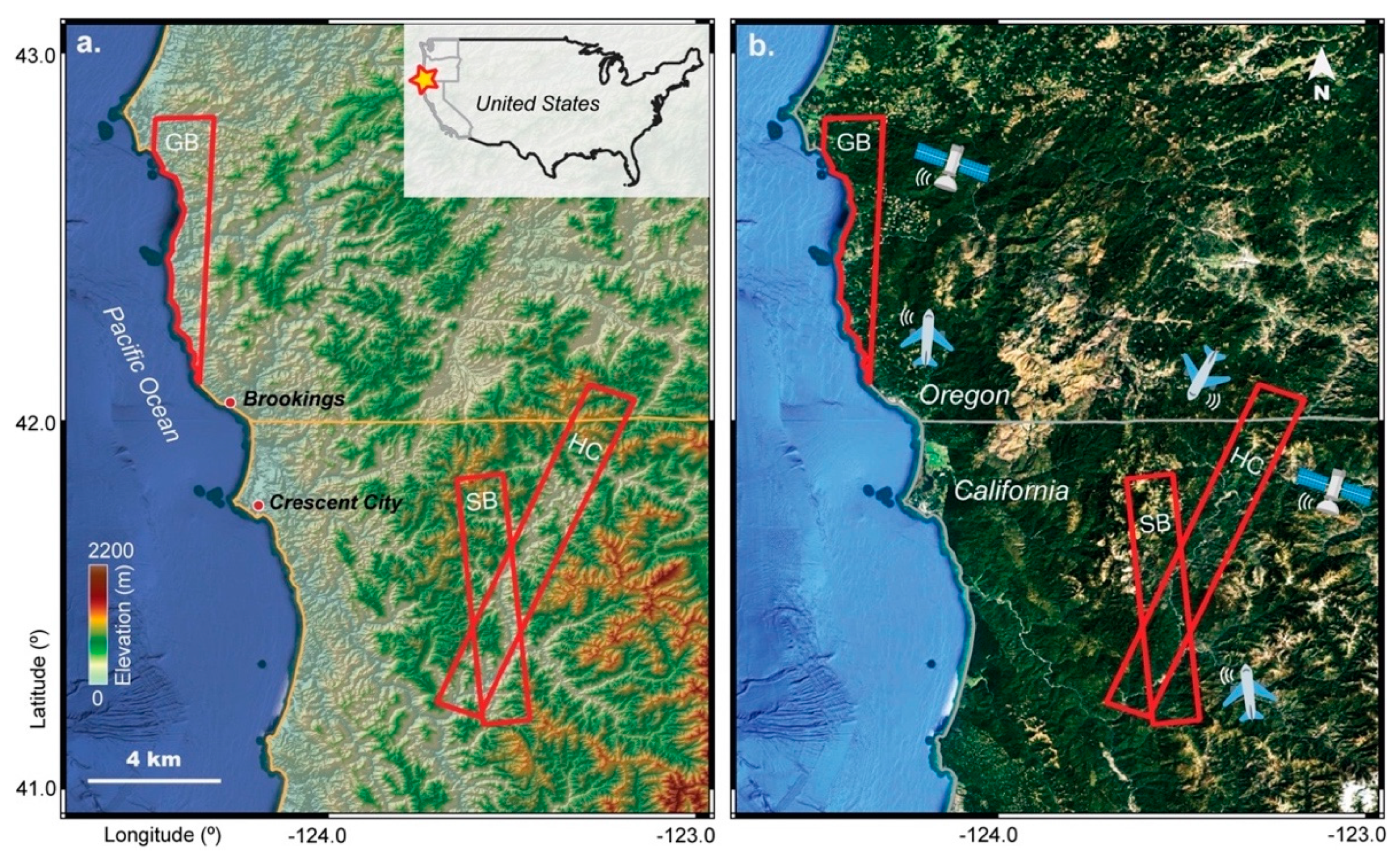
Figure 1. Airborne P-band SAR data coverage. (a) Red boxes denote the three regions that are covered by the repeat-pass P-band SAR data and the L-band ALOS-2 SAR imagery. These three regions are annotated as GB (Gold Beach), SB (Somes Bar), and HC (Happy Camp). The red star in the figure at the upper-right corner denotes the geographical location of the study area. The background hillshade map was produced from the National Elevation Datasets [9]. (b) A 2020 Google Earth true color image is used as background image to illustrate the vegetation coverage. Both the left-looking airborne P-band SAR and the right-looking satellite L-band SAR data (i.e., the ALOS-2 descending tracks) were acquired for the three target regions. Detailed flying path directions are given in Table 1.
Remotesensing 13 04575 g001
Figure 2. Detected geohazards over the three target regions using P-band InSAR. Red polygons outline the identified landslides from P-band InSAR. SAR interferograms and intensity changes of four selected areas (AD), which are marked on the hillshade maps at the upper-left corner, are depicted in four corresponding close-up figures. (A,B) show SAR interferograms of landslides from different radar look angles. (C,D) show the SAR intensity changes of a possible landslide runout and clear-cut, respectively. The true color images in (C,D) were accessed from Google Earth.
Remotesensing 13 04575 g002
Figure 3. Comparison of coherence for L-band and P-band InSAR. (ac) depict coherence maps of the P-band and L-band InSAR for the regions GB, SB, and HC, respectively. Multi-looking factors of 3 by 12 pixels (range by azimuth) were applied to both the P-band and L-band SAR data for the coherence estimations.
Remotesensing 13 04575 g003
Figure 4. Comparison of L-band and P-band InSAR for geohazard detection. Geographical location of the selected region was depicted by the red box in Figure 2. (ac) illustrate the wrapped interferogram, coherence, and unwrapped interferogram from the P-band AirMOSS acquisitions, respectively. (df) illustrate the wrapped interferogram, coherence, and unwrapped interferogram of the L-band ALOS-2 SAR images, respectively. The black polygons outline the active landslides, all of which slope towards the Pacific Ocean on the west. The white spots on the unwrapped interferograms represent the masked-out regions with low coherence.
Remotesensing 13 04575 g004
Figure 5. Sensitivity of radar sensors to ground deformation. (a) Sensitivity difference owing to radar frequency bands. (b) A sketch of minimum detectable ground displacement owing to radar look angle and dip angle of ground motion.
Remotesensing 13 04575 g005
Table 1. SAR data and corresponding technical parameters for the three target regions.
Target RegionBandWavelength (cm)Radar Look DirectionHeadng (°)Look Angle (°)SLC Pixel Size
(Rg × Az, m)
Multi-Looked Pixel Size (Rg × Az, m)SAR Acquisition Dates
Gold BeachP69.72Left2.943.11.7 × 0.65.0 × 7.2Dec 2020May 2021
L24.26right−169.736.34.3 × 3.84.3 × 7.6May 2020May 2021
Somes BarP69.72left−4.848.01.7 × 0.65.0 × 7.2Dec 2020May 2021
L24.26right−169.231.44.3 × 3.24.3 × 6.4Apr 2020Apr 2021
Happy CampP69.72 left−160.048.61.7 × 0.65.0 × 7.2Dec 2020May 2021
L24.26right−169.231.44.3 × 3.24.3 × 6.4Apr 2020Apr 2021
Publisher’s Note: MDPI stays neutral with regard to jurisdictional claims in published maps and institutional affiliations.