Article

Mapping Aquifer Storage Properties Using S-Wave Velocity and InSAR-Derived Surface Displacement in the Kumamoto Area, Southwest Japan

1
Department of Earth Resources Engineering, Kyushu University, Fukuoka 819-0395, Japan
2
Department of Geology, Faculty of Science, Fayoum University, Fayoum 63514, Egypt
3
International Institute for Carbon-Neutral Energy Research (I2CNER), Kyushu University, Fukuoka 819-0395, Japan
4
Department of Urban Management, Kyoto University, Kyoto 615-8510, Japan
5
National Research Institute for Earth Science and Disaster Resilience, Tsukuba 305-0006, Japan
6
Department of Regional Environment Systems, Shibaura Institute of Technology, Tokyo 135-8548, Japan
*
Author to whom correspondence should be addressed.
Remote Sens. 2021, 13(21), 4391; https://doi.org/10.3390/rs13214391
Submission received: 17 September 2021 / Revised: 29 October 2021 / Accepted: 29 October 2021 / Published: 31 October 2021

Abstract

:
We present a novel approach to mapping the storage coefficient (Sk) from InSAR-derived surface deformation and S-wave velocity (Vs). We first constructed a 3D Vs model in the Kumamoto area, southwest Japan, by applying 3D empirical Bayesian kriging to the 1D Vs profiles estimated by the surface-wave analysis at 676 measured points. We also used the time series of InSAR deformation and groundwater-level data at 13 well sites covering April 2016 and December 2018 and estimated the Sk of the confined aquifer. The Sk estimated from InSAR, and well data ranged from ~0.03 to 2 × 10⁻³, with an average of 7.23 × 10⁻³, values typical for semi-confined and confined conditions. We found a clear relationship between the Sk and Vs at well locations, indicating that the compressibility of an aquifer is related to the stiffness or Vs. By applying the relationship to the 3D Vs model, we succeeded in mapping the Sk in an extensive area. Furthermore, the estimated Sk distribution correlates well with the hydrogeological setting: semi-confined conditions are predicted in the Kumamoto alluvial plain with a high Sk. Our approach is thus effective for estimating aquifer storage properties from Vs, even where limited groundwater-level data are available. Furthermore, we can estimate groundwater-level variation from the geodetic data.

1. Introduction

Groundwater is a vital water resource in arid and remote regions. Given changing climate and human development, there is an increasing need for groundwater exploration, monitoring, and management. Effective groundwater management commonly relies on measurements of hydraulic head and storage properties. Groundwater from deep confined aquifers offers a viable source of fresh water and a buffer against severe drought conditions. Estimating hydrogeological properties is therefore important for developing sustainable, long-term water management strategies. Aquifer characteristics are usually estimated by analyzing pumping or recovery test data, including measuring water-level variations at monitoring wells [1,2,3,4,5,6]. However, the high cost of aquifer testing has restricted the monitoring of groundwater resources, and knowledge of their spatiotemporal evolution remains sparse [7].
Surface displacement due to hydraulic head change has occurred in many areas worldwide [8,9,10,11,12,13,14,15]. Terzaghi [16] proposed the poroelasticity theory that relates an aquifer system’s consolidation to its head change. Based on the consolidation curve of soil, when the hydraulic head of the deep aquifer declines (i.e., the effective stresses increase), compaction occurs in both aquifers and aquitards (i.e., consolidation), causing ground subsidence. In contrast, when the groundwater level recovers, the aquifer system expands, inducing surface uplift. The amount of aquifer deformation caused by changes in groundwater level is quantified by the skeletal storage coefficient (Sk), a parameter that describes the skeletal compressibility of the aquifer system [17]. In a confined aquifer, it has been known that the Sk is linked to matrix compressibility [18]. Therefore, mapping and characterizing the Sk is vital for understanding aquifer site characteristics.
Interferometric synthetic aperture radar (InSAR) time-series analysis can estimate time-series surface displacement with a high spatial resolution. Previous studies have used InSAR-derived surface displacement to estimate the Sk of confined aquifers because the Sk can be derived from the amount of surface displacement for a given groundwater-level change at the location of a groundwater observation well [17,19,20,21,22,23]. However, despite the effective InSAR-based approach, estimating the Sk is limited to the location of the wells where the groundwater level is observed. Therefore, if the distribution of groundwater wells is scattered or uneven, the spatial distribution of the Sk cannot be understood sufficiently.
Noninvasive methods through surface-wave analysis are widely used to estimate shallow S-wave velocity (Vs) structures (e.g., the work of [24]). In the microtremor survey method, surface waves included in passive seismic data (microtremor) are usually analyzed for estimating Vs structures [25]. The microtremor survey can be easily applied in various environments because it does not require active sources (i.e., vibroseis) but uses vibrations of the earth’s surface from human activities such as transportation or natural phenomena such as the flow of surface water [25]. Subsurface characterization using microtremor array measurements has become a powerful tool for detecting hidden faults [26], delineating fracture zones [27], and identifying soil-rock mixture landslides [28]. In addition, it is used for estimating site effects and seismic hazards in urban areas [29], detecting buried faults and structures during exploration for geothermal energy and minerals [30,31,32] and assessing liquefaction potential [33,34]. Previous studies further reported body- and surface-wave analyses to characterize aquifer systems [35,36,37]. From previous works, Vs is related to matrix compressibility [38,39,40], so shallow Vs structures derived from a microtremor survey could be used to predict properties of groundwater aquifers (e.g., storage coefficients).
This study proposes a novel approach for mapping the Sk with a high spatial resolution using Vs modeling, time series of surface displacement via InSAR, and groundwater-level data. In our proposed method, the Vs depth profiles were firstly estimated via observation using a miniature microtremor array and their 3D distribution using the 3D empirical Bayesian kriging method. The Sk of the confined aquifer was then estimated at groundwater well sites from the time series of InSAR displacement and groundwater-level data. An empirical relationship between the Sk and Vs was subsequently estimated using the data at the corresponding depth of the well locations. The spatial distribution of the Sk was finally estimated by applying the estimated SkVs relationship to the 3D Vs model. Therefore, this approach (i.e., mapping the Sk) facilitates estimating variations in groundwater levels from InSAR-derived surface displacement data.
We applied the proposed method to the data from 2016 to 2018 in the Kumamoto area, southwest Japan. In this area, the 2016 Kumamoto earthquake (Mw 7.0) occurred on 16 April 2016. Previous InSAR data analysis mapped and analyzed detailed surface displacement after the 2016 Kumamoto earthquake [41,42]. Specifically, Ishitsuka et al. [42] detected seasonal and transient surface displacements due to groundwater-level variations associated with the earthquake. Although the previous study has suggested a certain correlation between surface displacements and changes in groundwater levels through Sk, their spatial distribution in the Kumamoto area has not been fully investigated because limited groundwater-level data were available.

2. Study Area

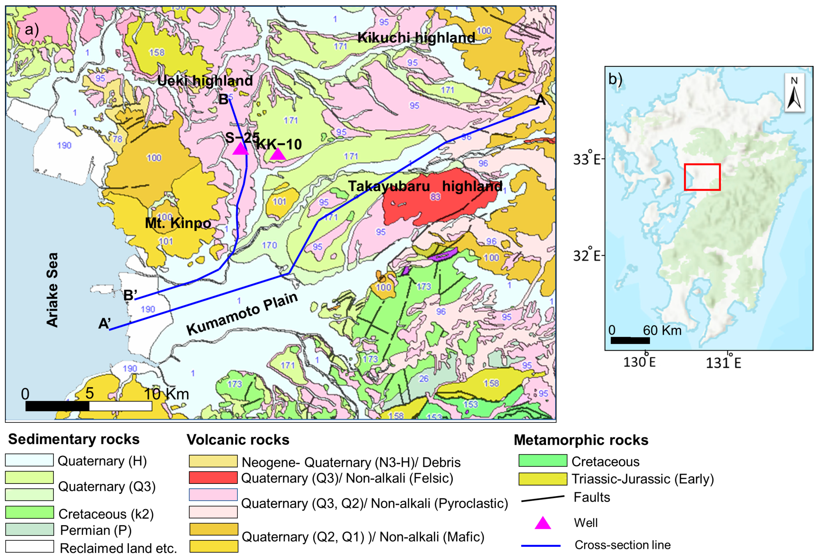
The Kumamoto area lies in central Kyushu Island, southwestern Japan (Figure 1). Hossain et al. [43,44] and Hosono et al. [45] reported its geological and hydrogeological settings and the geochemical processes controlling its groundwater. The eastern part of the study area is a volcanic area of the Quaternary age covered by pyroclastic-flow deposits erupted from the Aso volcano and alluvial deposits of the Pleistocene age. The western portion (especially coastal area) comprises the Kumamoto alluvial plain, consisting of Holocene Ariake clay [45,46]. The pyroclastic-flow deposits erupted from Mt. Aso over four periods between 90 and 30 ka and are classified into four types: Aso-4, Aso-3, Aso-2, and Aso-1. The pyroxene andesite called Togawa lava lies on the Aso-1, and the upper clacked part connects to the bottom of Aso-3 [46]. Two main faults are distributed in the study area: the Futagawa fault, which cuts the lava plateau and runs along the boundary between Cretaceous rocks and the Kumamoto plain, and the Hinagu fault, which runs from the south next to the alluvial plain toward the north through bedrocks to merge with the Futagawa fault. The 2016 Kumamoto earthquake sequence (Mw 7.0) along these two fault systems [47,48,49] caused widespread damage and disrupted infrastructure (e.g., the work of [50]).
Water supply in the Kumamoto area mainly relies on its abundant groundwater [51]. The Kumamoto aquifer system is mainly recharged from the western rim of Mount Aso, three major highland areas (Ueki, Kikuchi, and Takayubaru), and the midstream area of the Shira River being located in the north next to Takayubaru; its topography leads the groundwater flow direction to the southwest [52]. The Aso volcanic rock (pyroclastic flow and Togawa lava) is highly porous and permeable, making it an excellent aquifer (Figure 2) [53]. The unconfined aquifer is composed of recent pyroclastic-flow deposits (uppermost Aso-4) and partial marine sediments (<50 m deep). The underlying confined/semi-confined aquifer consists of older pyroclastic deposits and volcanic flow lavas (60–250 m) [45,54].
Figure 1. (a) Geological map of the study area [55]. (b) Location map of the study area (red rectangle) created using ArcGIS® software by Esri. The red rectangle indicates the location of panel a.
Remotesensing 13 04391 g001

3. Data Sets

3.1. InSAR Data

We used InSAR surface displacement data reported by Ishitsuka et al. [42], which was derived from persistent scatterer interferometry (PSI) analysis of ALOS-2/PALSAR-2 synthetic aperture radar (SAR) images. PSI analysis estimates time-series surface displacements using phase differences at coherent pixels called persistent scatters (PSs) [56,57]. In addition, PSI analysis has strategies to mitigate nuisance components of the phase differences attributed to changes in atmospheric states and errors in a digital elevation model. The accurate phase information at PSs and the mitigation of nuisance phase differences (phase differences caused by factors other than surface displacement) enable us to estimate accurate time-series surface displacements.
Ishitsuka et al. [42] used 28 ALOS-2/PALSAR-2 images acquired in a descending track mode orbit between 18 April 2016 and 10 December 2018. The PSI processing flow used in Ishitsuka et al. [42] was based on Kampes [57]. First, they selected interferometric pairs for single reference images. To select PS candidates (PSCs), they used an amplitude dispersion index [56] of 0.30. Following that, differential interferograms were created at the PSCs with a single-look. Next, they removed topographic phase components using a 10 m mesh external digital elevation model (DEM) provided by the Geospatial Information Authority of Japan. The stability of the interferometric phase of PSCs was then assessed based on phase coherence [56] and selected PSs as pixels above a coherence threshold of 0.80. Subsequently, the residual orbital fringes were removed, and the DEM errors and the displacement rates were estimated from a least-squares method. Phase unwrapping was then performed using a minimum cost flow algorithm [58]. Next, they reduced the atmospheric phase component by smoothing the change in the temporal phase because the atmospheric phase contribution is generally characterized by a high temporal frequency (e.g., the work of [56]). They showed that the line-of-sight surface displacements estimated from the PSI analysis are consistent with global navigation satellite system (GNSS) observations in the study area [42]. For characterizing the source of surface displacement, Ishitsuka et al. [42] created a model of temporal displacement caused by seasonal and long-term factors using sinusoidal and exponential functions, respectively, as follows:
U ( t ) = α { sin ( 2 π 365 t + θ ) sin ( θ ) } + β { e x p ( t k ) 1 }
where α is the amplitude of the seasonal displacement, and θ represents the phase shift that indicates the beginning of the seasonal displacement. The factor sin(θ) was used to ensure that U(0) = 0. Here, β is a coefficient representing the magnitude of the exponential function, and k is the exponential decay coefficient. From the least-squares method (Equation (1)), four unknown parameters (i.e., α, θ, β, and k) were estimated. To estimate θ and k , a grid search algorithm was used with intervals of 5° and a search range from −180 to 180° for θ and an interval of 10 with search range from 20 to 10,000 for k for determining the coefficients α and β . The least-squares method was applied during the grid search. After that, the optimal values of four parameters (α, θ, β , and k ) that reduce the error of mean square between the modeled and PSI time-series displacement were determined.
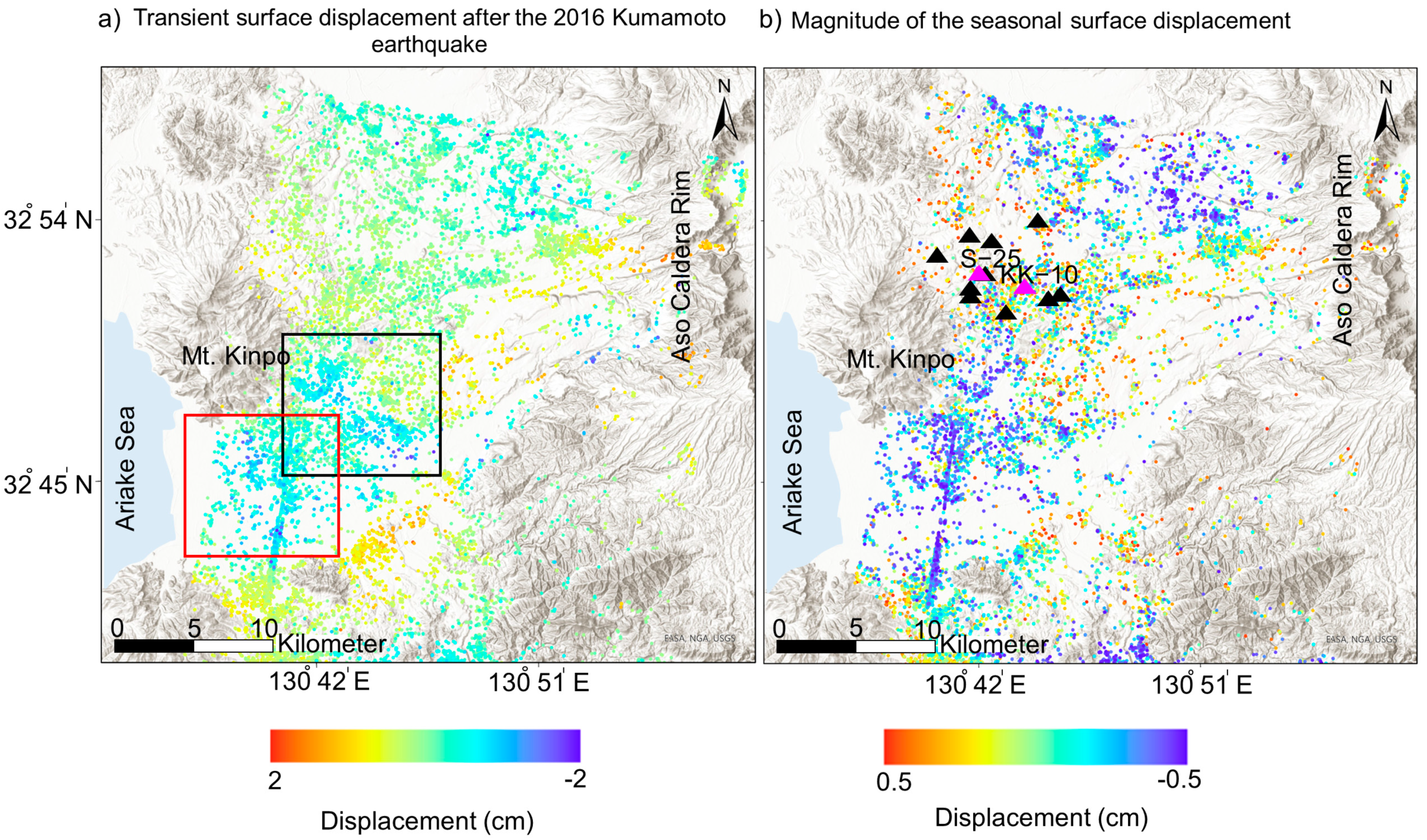
The estimated displacement maps show transient and seasonal surface displacements posterior to the 2016 Kumamoto earthquake (Figure 3). Transient displacements around the central and western part of the study area are attributed to groundwater migration through new coseismic ruptures (black rectangle in Figure 3a) and sediment compaction (the coastal area around the Ariake Sea (red rectangle in Figure 3a). Meanwhile, seasonal surface displacements based on Equation (1) in the northern and central parts are likely related to changes in groundwater levels, as shown in Figure 3b [42].

3.2. Piezometric Data

We used the time series of monthly average groundwater levels at 13 well sites (triangles in Figure 3b) acquired between 17 April 2016 and 10 December 2018. All wells were located in the northern part of the study area, where seasonal surface displacements were estimated with a magnitude up to 5 mm (Figure 3b; Ishitsuka et al. [42]), and measured the groundwater level at the confined aquifer. The upper and lower ends of the strainer depth for each well are shown in Table 1. For most wells, the strainer depth ranges from 50 to 170 m (Table 1), corresponding to a single aquifer. Surface displacements (topographic changes) were induced up to a few meters by the 2016 Kumamoto earthquake. Each well top height was re-measured after the earthquake (2017) by the leveling, and post-earthquake groundwater level (m a.s.l.) was adjusted by updated height data.

3.3. Three-Dimensional S-Wave Velocity Model

To estimate the spatial variation of S-wave velocities in the study area, we used 1D Vs profiles estimated from microtremors using a miniature seismic array [59] at 676 observation points by the National Research Institute for Earth Science and Disaster Resilience (NIED; [60]). The interval between observation points ranged from approximately 100 m to 1000 m. To collect microtremor data, we conducted microtremor surveys combining a triangular array (radius: 0.6 m) with one central station and an irregular triangular array (side ranges from 4 to 10 m or more) at each observation point with a sampling frequency of 200 Hz (Figure 4). The microtremor surveys were conducted using an integrated, portable housing seismometer, JU410, manufactured by the Hakusan Corporation based on the cloud microtremor observation system [61].
First, the horizontal/vertical (H/V) spectral ratio and the phase velocity dispersion curves of Rayleigh waves were estimated from the observed microtremors. Second, the Vs structure at each observation point was estimated by the joint inversion of the H/V spectral ratio and dispersion curves using a genetic algorithm inversion [62,63]. Finally, geostatistical interpolation by Empirical Bayesian Kriging 3D (EBK3D) was applied to predict the Vs at unsampled points in 3D space. EBK3D is available in ArcGIS Pro software as a geoprocessing tool. Empirical Bayesian kriging (EBK) [64] is different from other kriging methods; the EBK-based approach considers standard prediction errors and automatically estimates the semivariogram parameters using restricted maximum likelihood. EBK involves the following steps:
  • Estimation of a semivariogram model from the original data;
  • Prediction of data at each of the observed points from the semivariogram;
  • Estimation of a new semivariogram model and its weight from the predicted data;
  • Repeating steps 2 and 3 creates a spectrum of the semivariogram models;
  • Prediction of Vs and their standard errors at unmeasured locations using these weights.

4. Methodology: Mapping the Skeletal Storage Coefficient

The skeletal storage coefficient, Sk, of a confined aquifer (also called storativity) is a dimensionless measure of the volume of water released from or taken into storage per unit surface area of the aquifer per unit change in the hydraulic head [65]. It is defined as Sk = Ss∙b, where Ss is specific storage (L−1), and b is the thickness (L) of the aquifer. We estimated the Sk of the confined aquifer system from 2016 to 2018 using the following relationship with surface displacement (Δb, from PSI) and the change in the hydraulic head (Δh) at the 13 well sites [66,67]:
S k = Δ b Δ h
This relationship is valid when the deformation is elastic. Theoretically, the coefficient is described by the function of aquifer compressibility (Equation (3)), assuming that the porosity does not change significantly with elastic deformation [68]:
S k = ρ g ( c m + n c w ) b
where ρ is the pore fluid density, g is the acceleration due to gravity, c m is the matrix compressibility, n is the porosity, c w is the pore fluid compressibility, and b is the thickness (L) of the aquifer. Thus, the soil’s (matrix) compressibility represents its volume change in response to the applied pressure [68].
Before estimating Sk using Equation (2), we eliminated multivariate outliers in the data using Z-score. It is a statistical method to measure the divergence of observed data points from its mean. Z-score can be computed as follows:
Z = X i μ σ ,
where X i is i th sample point, μ refers to the mean of the data set, and σ is the standard deviation. Since we analyzed multivariate data (i.e., surface deformation and hydraulic head), we computed Z-score in 2D space. We define outliers if the Z-score of the data exceeds the threshold (Figure 5).
To predict the Sk values where groundwater-level data (i.e., well data) were not available, we proposed a new approach based on Vs. Previous studies show a relationship between Vs and aquifer compressibility. For example, Cha et al. [38] noted that shear stiffness and compressibility could be estimated using Vs, as they reported relationships between soil compressibility and the small strain parameters used in velocity–stress power relations. These relationships suggested that cemented dense sediments are characterized by low compressibility and high Vs and vice versa. Martin et al. [39] investigated a shear zone formed by an igneous rock to estimate hydraulic conductivity and normal stiffness using borehole data. They reported that low stress and stiffness regions exhibit high storage coefficients and hydraulic conductivity. Li et al. [69] derived a formula for rock compressibility based on soil mechanics concepts [70], indicating the dependence of rock compressibility on the rigidity of rock minerals. Therefore, the Sk can be linked to Vs. We thus constructed the SkVs relationship by plotting the Sk and Vs at the water level depth estimated at each well. Using the SkVs relationship, we then estimated Sk values from only the Vs. This approach enables us to map the Sk distribution where only Vs data were available.

5. Results and Interpretation

5.1. Three-Dimensional S-Wave Velocity
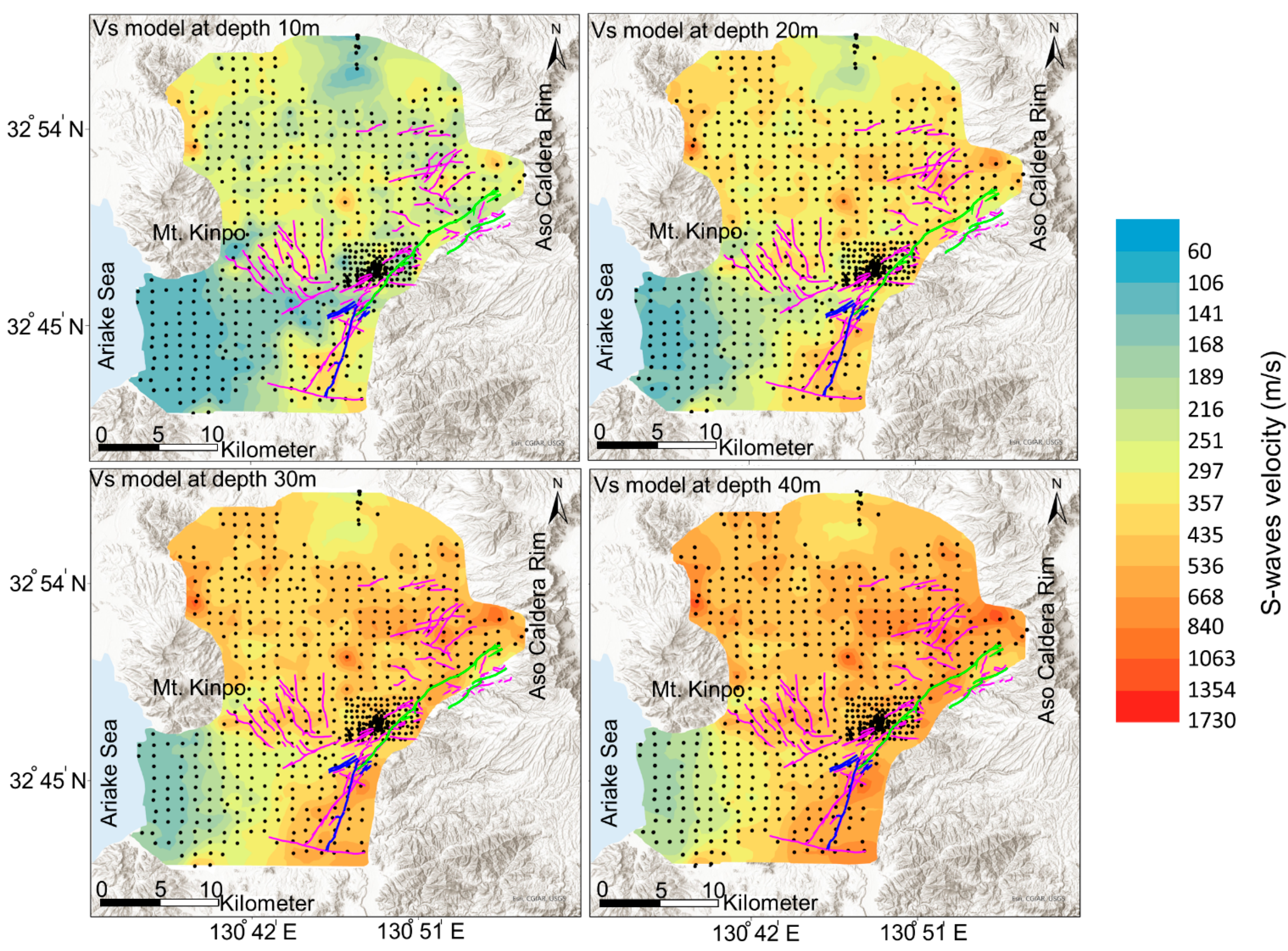
Figure 6 shows maps of Vs at different depths. A low-velocity zone observed in the western coastal area correlated well with the Kumamoto alluvial plain covered by Holocene Ariake clay. We calculated the average Vs for a depth down to 30 m (Vs30) and could identify the faulted/fractured zones as low-Vs zones in the map of Vs30 (Figure 7) that coincided with the Futagawa fault system. We compared surface displacements by InSAR data analysis with the Vs structure to examine whether surface displacements are linked to subsurface properties. The low-velocity regions correlated with surface displacement associated with the 2016 Kumamoto earthquake sequence found by the InSAR technique [41,42,47]. The rock strength is reduced by faulting and fracturing, and such reduction is reflected by a reduction in shear coupling and Vs [71]. Therefore, we demonstrate the potential of using microtremors to detect faulted/fractured zones.
Based on the Vs model (Figure 6), furthermore, we can evaluate the liquefaction area. During liquefaction, the effective stress is close to zero because of the increase in pore pressure. A mechanism of undrained consolidation for soil liquefaction has often been discussed [72,73] based on the theory of poroelasticity [16] that relates effective stress to the pressure of the pore fluids. A reduction in effective stress associated with increasing pore pressure should be reflected by reducing the mechanical strength of sediments that weakens them, so the Vs is a very important parameter to evaluate liquefaction. The soil in the southwestern Kumamoto area was classified as soft or stiff in the Vs30 map according to the classification by the National Earthquake Hazard Reduction Program (NEHRP)and the American Society of Civil Engineers (ASCE) [74,75] (Figure 7). Velocities down to a depth of around 20 m were lower than 200 m/s in the western part (Figure 6), representing an upper limit of the range of velocities in liquefiable soil [76]. The region of low velocity is consistent with the area affected by liquefaction during the 2016 Kumamoto earthquake.
Figure 6. S-wave velocity distribution at depths of 10–40 m. Black dots are Vs observation points. Purple lines are linear surface ruptures mapped using InSAR by Fujiwara et al. [47], and the green and blue lines refer to Futagawa and Hinagu faults [77].
Remotesensing 13 04391 g006
Figure 7. The average Vs for the upper 30 m of a soil profile. Black dots are Vs observation points, purple lines are linear surface ruptures mapped using InSAR by Fujiwara et al. [47], and the green and blue lines refer to Futagawa and Hinagu faults [77]. Background map is from ArcGIS® software by Esri.
Remotesensing 13 04391 g007

5.2. Skeletal Storage Coefficient and S-Waves Velocity Relationship

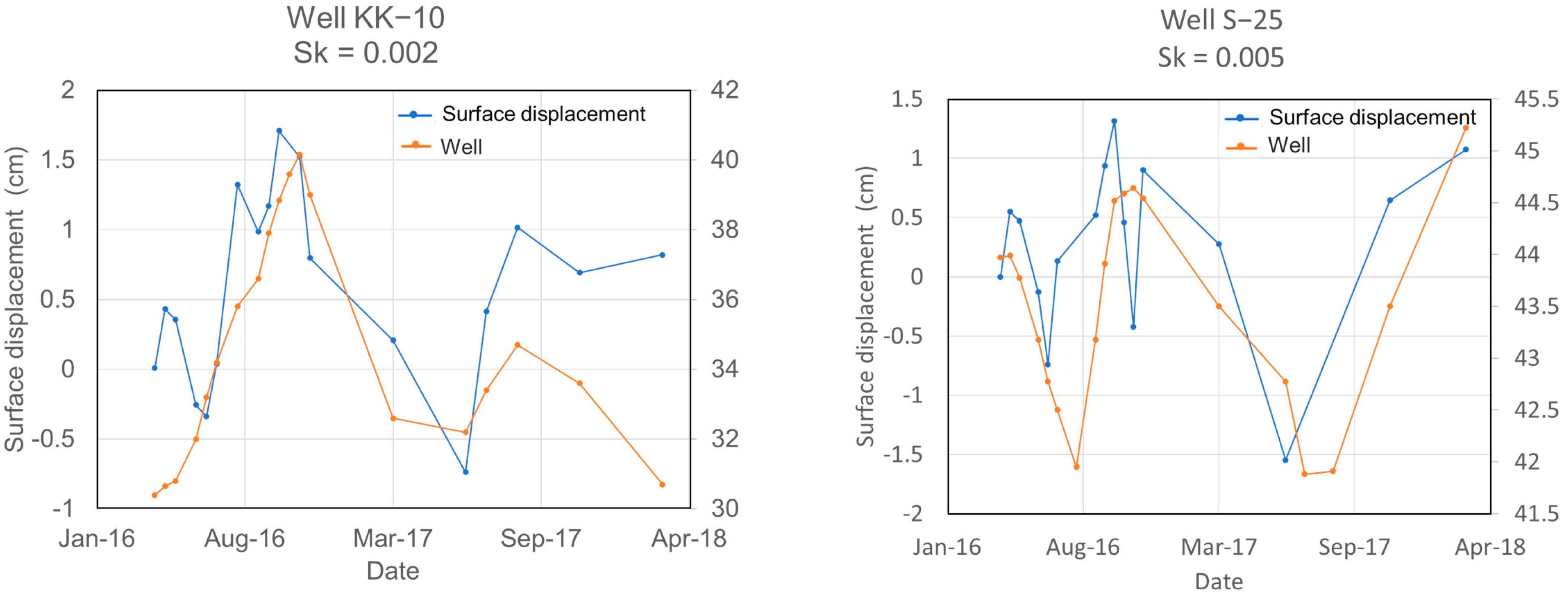
We used the time series of InSAR-derived surface deformation and groundwater-level data to determine the storage properties of the confined aquifer at 13 well sites (Figure 3b). Table 1 shows that the storage coefficient values at the 13 sites ranged from ~0.03 to 2 × 10⁻³, with an average of 7.23 × 10⁻³ after outlier removal using Z-score. Most of the correlations between InSAR displacement and well data are statistically significant based on the p-value (<0.05). Since the correlation at SS-17 does not show statistical significance, we excluded the estimated Sk in the following analysis. Pearson’s correlation coefficient (R) and the standard errors of the Sk estimates are also shown in Table 1. The estimated values of Sk correspond to those of semi-confined and confined conditions [78,79]. The deep aquifer in the study area is semi-confined to confined due to the discontinuity of the impermeable clay layer of lacustrine sediments [45].
We then observed a negative correlation between the Sk and Vs (Figure 8). Exponential curve fitting found the following empirical relationship between Sk and Vs:
S k = 6.214 × Vs 1.166
Around 83.3% of data points lie within the ±95% confidence interval of the relationship in Equation (5). The relationship between Sk and Vs can be explained by the relationship between compressibility and stiffness (or Vs), as mentioned in the previous sections.

5.3. Mapping of the Skeletal Storage Coefficient to Monitor Groundwater Level from InSAR Data

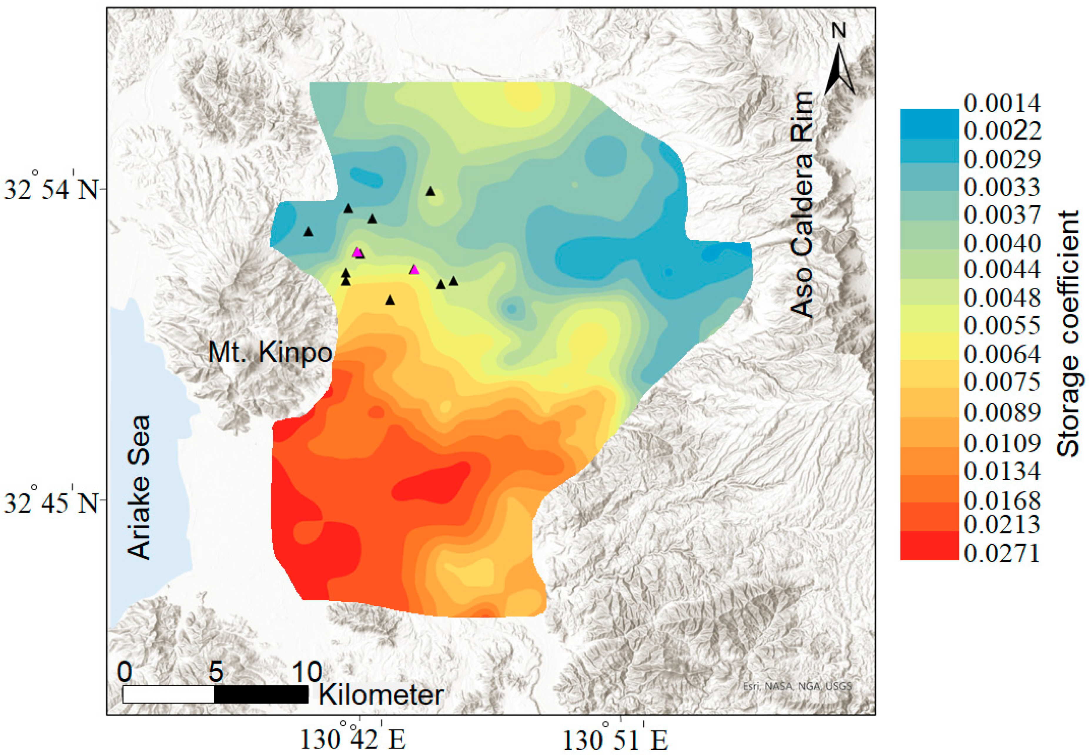
To map Sk, we applied the Sk–Vs relationship to areas where only Vs were estimated from the microtremor survey (Figure 9). The estimated Sk (Figure 9) is correlated with the hydrogeological setting, where the Sk greater than 0.01 in the southwestern part of the study area reflected semi-confined conditions due to discontinuity of the impermeable clay layer of lacustrine sediments underlying the deep aquifer [45]. This area is covered by an alluvial plain and terrace deposits (Figure 1) composed of large amounts of unconsolidated sediments with high compressibility and low Vs. Wilson and Wöhling [80] found that vertical transmissivity and storage coefficient decrease significantly with depth due to the increasing tortuosity of permeable flow pathways in the deeper parts causing groundwater to flow horizontally through shallow pathways.

6. Discussion

This study demonstrates the feasibility of using Vs, InSAR-derived surface deformation, and groundwater-level data to map the storage properties of a confined aquifer at high spatial resolution (Figure 9). Therefore, we can estimate the spatiotemporal variation of groundwater level based on geodetic data (i.e., surface displacement derived from InSAR or GNSS). Our approach could offer great potential for improving the groundwater flow modeling by using the estimated Sk. However, the successful application of the approach requires consideration of the investigation depth of Vs estimated from microtremor surveys. As the Vs at a water level depth is used to construct a relationship between Sk and Vs, microtremor surveys need to be designed to cover the depth of the water level in a study area.
In general, the uncertainty of Sk occurs for the following reasons.
(1)
The Sk is biased if the horizontal displacement is not considered in the Sk calculation [81]. In our study area, horizontal fluid movement occurs over the groundwater system [23].
(2)
Monitoring wells observe water from one aquifer in the saturated confined aquifer system [81]. Hoffmann et al. [23] mentioned that the estimated Sk would be inaccurate if hydraulic heads at piezometers do not represent the average local condition in the groundwater system. Most of the wells in this study correspond to a single confined aquifer based on the strainer depth information. Although there is a possibility that the temporal variation of the deeper aquifer may generate errors in estimating Sk, we assume the influence of the shallowest confined aquifer is dominant.
(3)
Error in measurements of InSAR displacement is due to atmospheric phase effects. In this study, temporal filtering was used to mitigate the error of atmospheric contribution. Because PSI displacements were consistent with the F3 solution of GEONET, GSI, Japan, the error in measurements of InSAR displacement could be minor.
(4)
Incomplete removal of the long-term subsidence from the land deformation time series for case studies of high subsidence rate. To completely separate long-term trends of subsidence and hydraulic head from their time series, daily or weekly measurements of InSAR and head time series for several years are required [82].
Although these factors generate uncertainty for the estimated Sk, a part of uncertainty was suppressed by removing outliers of InSAR displacements and groundwater-level data using a Z-score.
To validate the Sk–Vs relationship, furthermore, we applied a statistical method called repeated holdout cross-validation. In this method, the original data are split into two data sets. One data set is used for testing (validation) of the model, and another is used as a training data set. Validation and training data sets contain four and nine data points, respectively. Exponential curve fitting was applied to the training data set, and the resulting model was used to evaluate the root mean square error (RMSE) of the testing data set as follows:
RMSE = 1 N i = 1 N [ Z ( x i ) Z ( y i )   ] 2
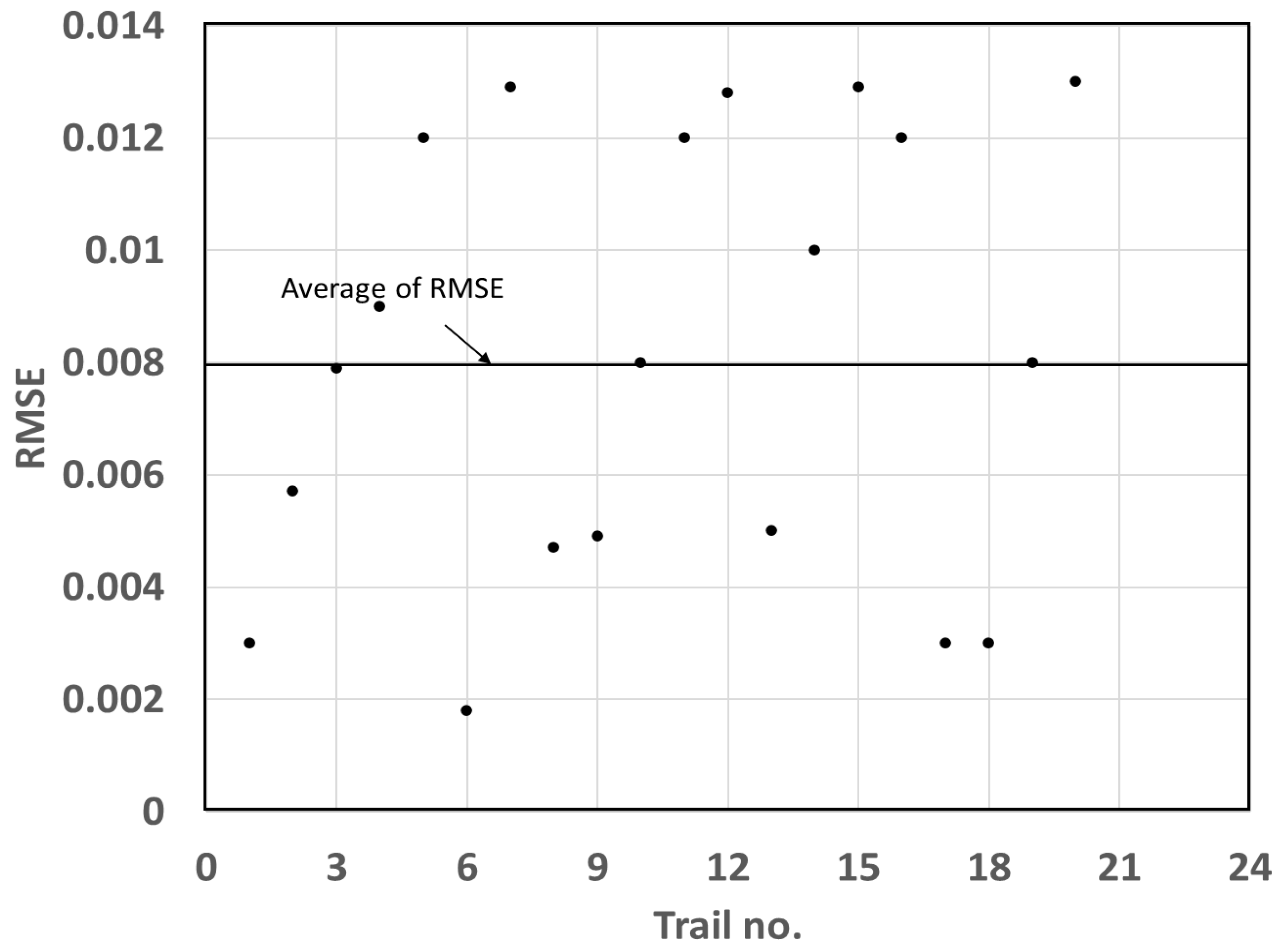
where Z ( x i )   and Z ( y i ) are measured and estimated Sk values of the i sampling point, respectively, and N is the total number of observation points. In our case, N corresponds to the number of validation data sets (N = 3). The method is repeated 20 times (trials) to estimate the RMSE of each trial (Figure 10). The low RMSE (averaged RMSE = 8.1 × 10⁻³) indicates that the constructed equation (i.e., Equation (5)) can estimate Sk values at unmeasured points with a minor error.
Thus, if we can validate the parameters used in our model, this approach could be used to map the Sk and temporal variation of groundwater levels from the surface deformation (geodetic data) at a lower cost.

7. Conclusions

This study proposes a new approach to map storage coefficients from surface displacements, groundwater-level data, and a high-resolution Vs model. Its main findings are summarized as follows.
  • The zone of low Vs found by the microtremor survey could have coincided with the Futagawa fault zone;
  • Sk of the confined aquifer ranges between ~0.03 and 2 × 10⁻³, with an average of 7.23 × 10⁻³, reflecting semi-confined and confined conditions;
  • An empirical relationship between the Sk and Vs was found, indicating that aquifer compressibility is linked to its stiffness and Vs;
  • The map of Sk estimated from the empirical relationship correlates with the hydrogeological setting and can be used to estimate the spatiotemporal variation of groundwater-level based on the geodetic data.
In conclusion, our approach can effectively estimate aquifer storage properties from S-wave velocities even where limited groundwater level data are available.

Author Contributions

Conceptualization, M.M. and T.T.; Data curation, M.M., K.I. (Kazuya Ishitsuka), S.S. and K.I. (Kiyoshi Ide); Formal analysis, M.M.; Funding acquisition, T.T.; Investigation, T.T.; Methodology, M.M., T.T. and T.I.; Project administration, T.T.; Software, M.M.; Supervision, T.T.; Validation, M.M. and T.T.; Visualization, M.M., T.T. and T.I.; Writing—original draft, M.M.; Writing—review and editing, T.T., T.I., K.I. (Kazuya Ishitsuka), and K.I. (Kiyoshi Ide). All authors have read and agreed to the published version of the manuscript.

Funding

The first author was funded by a full scholarship from the Ministry of Higher Education of the Arab Republic of Egypt, through a grant-in-aid by the Egypt–Japan Education Partnership (EJEP) for developing human resources, which is regarded as an initial goal in the long-term development plan in Egypt. This research is partially supported by JSPS KAKENHI (JP20H01997).

Institutional Review Board Statement

Not applicable.

Informed Consent Statement

Not applicable.

Data Availability Statement

Data sharing is not applicable.

Acknowledgments

Microtremor data used in this study were acquired by the National Research Institute for Earth Science and Disaster Resilience, Tsukuba, Japan (NIED). The groundwater-level data used in this study were measured by several public institutions and corrected by the working group of the Japan Association of Groundwater Hydrology (JAGH). We are grateful for the support provided by the Ministry of Higher Education of the Arab Republic of Egypt and NIED.

Conflicts of Interest

The authors declare no conflict of interest.

References

  1. Banton, O.; Bangoy, L.M. A new method to determine storage coefficient from pumping test recovery data. Groundwater 1996, 34, 772–777. [Google Scholar] [CrossRef]
  2. Bardsley, W.E. DISCUSSION OF “Estimation of Storativity from Recovery Data,” by PN Ballukraya and KK Sharma. Groundwater 1992, 30, 272–273. [Google Scholar] [CrossRef]
  3. Chapuis, R.P. DISCUSSION OF “Estimation of Storativity from Recovery Data”, by PN Ballukraya and KK Sharma. Groundwater 1992, 30, 269–272. [Google Scholar] [CrossRef]
  4. Theis, C.V. The relation between the lowering of the piezometric surface and the rate and duration of discharge of a well using ground-water storage. Eos Trans. Am. Geophys. Union 1935, 16, 519–524. [Google Scholar] [CrossRef]
  5. Ballukraya, P.N.; Sharma, K.K. Estimation of storativity from recovery data. Groundwater 1991, 29, 495–498. [Google Scholar] [CrossRef]
  6. Jacob, C.E. The recovery method for determining the coefficient of transmissivity. US Geol. Surv. Water Supply Pap. 1963, 1536–I, 281–292. [Google Scholar]
  7. Shah, T.; Molden, D.; Sakthivadivel, R.; Seckler, D. Global groundwater situation: Opportunities and challenges. Econ. Polit. Wkly. 2001, 4142–4150. [Google Scholar]
  8. Gabrysch, R.K.; Bonnet, C.W. Land-Surface Subsidence in the Houston-Galveston Region, Texas; Texas Water Development Board: Austin, TX, USA, 1975; Volume 74. [Google Scholar]
  9. Hix, G.L. Land subsidence and ground water withdrawal. Water Well J. 1995, 49, 37–39. [Google Scholar]
  10. Sun, H.; Grandstaff, D.; Shagam, R. Land subsidence due to groundwater withdrawal: Potential damage of subsidence and sea level rise in southern New Jersey, USA. Environ. Geol. 1999, 37, 290–296. [Google Scholar] [CrossRef]
  11. Zhang, Y.; Xue, Y.-Q.; Wu, J.-C.; Yu, J.; Wei, Z.-X.; Li, Q.-F. Land subsidence and earth fissures due to groundwater withdrawal in the Southern Yangtse Delta, China. Environ. Geol. 2008, 55, 751. [Google Scholar] [CrossRef]
  12. Modoni, G.; Darini, G.; Spacagna, R.L.; Saroli, M.; Russo, G.; Croce, P. Spatial analysis of land subsidence induced by groundwater withdrawal. Eng. Geol. 2013, 167, 59–71. [Google Scholar] [CrossRef]
  13. Khakim, M.Y.N.; Tsuji, T.; Matsuoka, T. Lithology-controlled subsidence and seasonal aquifer response in the Bandung basin, Indonesia, observed by synthetic aperture radar interferometry. Int. J. Appl. Earth Obs. Geoinf. 2014, 32, 199–207. [Google Scholar] [CrossRef] [Green Version]
  14. Ishitsuka, K.; Fukushima, Y.; Tsuji, T.; Yamada, Y.; Matsuoka, T.; Giao, P.H. Natural surface rebound of the Bangkok plain and aquifer characterization by persistent scatterer interferometry. Geochem. Geophys. Geosystems. 2014, 15, 965–974. [Google Scholar] [CrossRef]
  15. Zhu, L.; Gong, H.; Li, X.; Wang, R.; Chen, B.; Dai, Z.; Teatini, P. Land subsidence due to groundwater withdrawal in the northern Beijing plain, China. Eng. Geol. 2015, 193, 243–255. [Google Scholar] [CrossRef]
  16. Terzaghi, K. Erdbaumechanik auf Bodenphysikalischer Grundlage; Deuticke, F., Leipzig, Eds.; Food and Agriculture Organization of the United Nations: Beltsville, MD, USA; Washington, DC, USA, 1925. [Google Scholar]
  17. Chen, J.; Knight, R.; Zebker, H.A.; Schreüder, W.A. Confined aquifer head measurements and storage properties in the San Luis Valley, Colorado, from spaceborne InSAR observations. Water Resour. Res. 2016, 52, 3623–3636. [Google Scholar] [CrossRef] [Green Version]
  18. Riley, F.S. Analysis of borehole extensometer data from central California. Land Subsid. 1969, 2, 423–431. [Google Scholar]
  19. Chaussard, E.; Bürgmann, R.; Shirzaei, M.; Fielding, E.J.; Baker, B. Predictability of hydraulic head changes and characterization of aquifer-system and fault properties from InSAR-derived ground deformation. J. Geophys. Res. Solid Earth 2014, 119, 6572–6590. [Google Scholar] [CrossRef]
  20. Ezquerro, P.; Herrera, G.; Marchamalo, M.; Tomás, R.; Béjar-Pizarro, M.; Martínez, R. A quasi-elastic aquifer deformational behavior: Madrid aquifer case study. J. Hydrol. 2014, 519, 1192–1204. [Google Scholar] [CrossRef] [Green Version]
  21. Reeves, J.A.; Knight, R.; Zebker, H.A.; Kitanidis, P.K.; Schreüder, W.A. Estimating temporal changes in hydraulic head using InSAR data in the San Luis Valley, Colorado. Water Resour. Res. 2014, 50, 4459–4473. [Google Scholar] [CrossRef]
  22. Béjar-Pizarro, M.; Ezquerro, P.; Herrera, G.; Tomás, R.; Guardiola-Albert, C.; Hernández, J.M.R.; Merodo, J.A.F.; Marchamalo, M.; Martínez, R. Mapping groundwater level and aquifer storage variations from InSAR measurements in the Madrid aquifer, Central Spain. J. Hydrol. 2017, 547, 678–689. [Google Scholar] [CrossRef] [Green Version]
  23. Hoffmann, J.; Zebker, H.A.; Galloway, D.L.; Amelung, F. Seasonal subsidence and rebound in Las Vegas Valley, Nevada, observed by synthetic aperture radar interferometry. Water Resour. Res. 2001, 37, 1551–1566. [Google Scholar] [CrossRef]
  24. Foti, S.; Hollender, F.; Garofalo, F.; Albarello, D.; Asten, M.; Bard, P.-Y.; Comina, C.; Cornou, C.; Cox, B.; Di Giulio, G.; et al. Guidelines for the good practice of surface wave analysis: A product of the InterPACIFIC project. Bull. Earthq. Eng. 2018, 16, 2367–2420. [Google Scholar] [CrossRef]
  25. Okada, H.; Suto, K. The Microtremor Survey Method; Society of Exploration Geophysicists: Houston, TX, USA, 2003; ISBN 1560801204. [Google Scholar]
  26. Khalili, M.; Mirzakurdeh, A.V. Fault detection using microtremor data (HVSR-based approach) and electrical resistivity survey. J. Rock Mech. Geotech. Eng. 2019, 11, 400–408. [Google Scholar] [CrossRef]
  27. Wu, C.F.; Huang, H.C. Detection of a fracture zone using microtremor array measurementDetection of a fracture zone. Geophysics 2019, 84, 33–40. [Google Scholar] [CrossRef]
  28. Du, Y.N.; Xu, P.F.; Ling, S.Q. Microtremor survey of soil-rock mixture landslide: A case study of landslide in Baidian Township, Hengyang City. Chinese J. Geophys. 2018, 61, 1596–1604. [Google Scholar]
  29. Bonnefoy-Claudet, S.; Baize, S.; Bonilla, L.F.; Berge-Thierry, C.; Pasten, C.; Campos, J.; Verdugo, R. Site effect evaluation in the basin of Santiago de Chile using ambient noise measurements. Geophys. J. Int. 2009, 176, 925–937. [Google Scholar] [CrossRef] [Green Version]
  30. Xu, P.; Ling, S.; Zhang, D.; Dai, K.; Li, C.; Du, J. Mapping deeply-buried geothermal faults using microtremor array analysis. Geophys. J. Int. 2012, 188, 115–122. [Google Scholar] [CrossRef]
  31. Xu, P.; Li, S.H.; Du, J.G.; Ling, S.Q.; Guo, H.L. Microtremor Survey Method: A New Geophysical Method for Dividing Strata and Detecting the Buried Fault Structures; Acta Petrologica Sinica: Beijing, China, 2013; Volume 29, pp. 1841–1845. [Google Scholar]
  32. Tian, B.; Xu, P.; Ling, S.; Du, J.; Xu, X.; Pang, Z. Application effectiveness of the microtremor survey method in the exploration of geothermal resources. J. Geophys. Eng. 2017, 14, 1283–1289. [Google Scholar] [CrossRef] [Green Version]
  33. Rezaei, S.; Choobbasti, A.J. Liquefaction assessment using microtremor measurement, conventional method and artificial neural network case study: Babol, Iran. Front. Struct. Civ. Eng. 2014, 8, 292–307. [Google Scholar] [CrossRef]
  34. Takahashi, K.; Tsuji, T.; Ikeda, T.; Nimiya, H.; Nagata, Y.; Suemoto, Y. Underground structures associated with horizontal sliding at Uchinomaki hot springs, Kyushu, Japan, during the 2016 Kumamoto earthquake. Earth Planets Sp. 2019, 71, 87. [Google Scholar] [CrossRef]
  35. Castagna, J.P.; Batzle, M.L.; Eastwood, R.L. Relationships between compressional-wave and shear-wave velocities in clastic silicate rocks. Geophysics 1985, 50, 571–581. [Google Scholar] [CrossRef]
  36. Grelle, G.; Guadagno, F.M. Seismic refraction methodology for groundwater level determination:“Water seismic index. ” J. Appl. Geophys. 2009, 68, 301–320. [Google Scholar] [CrossRef]
  37. Serdyukov, A.S.; Yablokov, A.V.; Chernyshov, G.S.; Azarov, A.V. The surface waves-based seismic exploration of soil and ground water. In IOP Conference Series: Earth and Environmental Science; IOP Publishing: Bristol, England, 2017; Volume 53, p. 12010. [Google Scholar]
  38. Cha, M.; Santamarina, J.C.; Kim, H.-S.; Cho, G.-C. Small-strain stiffness, shear-wave velocity, and soil compressibility. J. Geotech. Geoenviron. Eng. 2014, 140, 6014011. [Google Scholar] [CrossRef] [Green Version]
  39. Martin, C.D.; Davison, C.C.; Kozak, E.T. Characterizing normal stiffness and hydraulic conductivity of a major shear zone in granite. In Proceedings of the International Symposium on Rock Joints, Loen, France, 4–6 June 1990; pp. 549–556. [Google Scholar]
  40. Rutqvist, J.; Noorishad, J.; Tsang, C.; Stephansson, O. Determination of fracture storativity in hard rocks using high-pressure injection testing. Water Resour. Res. 1998, 34, 2551–2560. [Google Scholar] [CrossRef]
  41. Ishitsuka, K.; Tsuji, T.; Matsuoka, T. Surface Displacement Around the Ezu Lake and the Suizenji Area Associated with the 2016 Kumamoto Earthquake. J. Remote Sens. Soc. Jpn. 2016, 36, 218–222. [Google Scholar]
  42. Ishitsuka, K.; Tsuji, T.; Lin, W.; Kagabu, M.; Shimada, J. Seasonal and transient surface displacements in the Kumamoto area, Japan, associated with the 2016 Kumamoto earthquake: Implications for seismic-induced groundwater level change. Earth Planets Sp. 2020, 72, 144. [Google Scholar] [CrossRef]
  43. Hossain, S. Geochemical modeling of groundwater evolution in a volcanic aquifer system of Kumamoto area, Japan. In American Geophysical Union (AGU) Fall Meeting Abstracts; American Geophysical Union: Washington, DC, USA, 2013. [Google Scholar]
  44. Hossain, S. Geochemical processes controlling fluoride enrichment in groundwater at the western part of Kumamoto area, Japan. Water Air Soil Pollut. 2016, 227, 385. [Google Scholar] [CrossRef]
  45. Hosono, T.; Hossain, S.; Shimada, J. Hydrobiogeochemical evolution along the regional groundwater flow systems in volcanic aquifers in Kumamoto, Japan. Environ. Earth Sci. 2020, 79, 410. [Google Scholar] [CrossRef]
  46. Mahara, Y.; Igarashi, T.; Kudo, A. Groundwater Origin and Evolution from Dissolved Helium Isotopes in the Kumamoto Plain. 1997. Available online: https://www.osti.gov/etdeweb/biblio/307537 (accessed on 1 September 2021).
  47. Fujiwara, S.; Yarai, H.; Kobayashi, T.; Morishita, Y.; Nakano, T.; Miyahara, B.; Nakai, H.; Miura, Y.; Ueshiba, H.; Kakiage, Y.; et al. Small-displacement linear surface ruptures of the 2016 Kumamoto earthquake sequence detected by ALOS-2 SAR interferometry. Earth Planets Sp. 2016, 68, 160. [Google Scholar] [CrossRef] [Green Version]
  48. Goto, H. Geomorphic features of surface ruptures associated with the 2016 Kumamoto earthquake in and around the downtown of Kumamoto City, and implications on triggered slip along active faults. Earth Planets Sp. 2017, 69, 26. [Google Scholar] [CrossRef] [Green Version]
  49. Ishitsuka, K.; Tsuji, T. Mapping Surface Displacements and Aquifer Characteristics Around the Kumamoto Plain, Japan, Using Persistent Scatterer Interferometry. In Proceedings of the IGARSS 2019-2019 IEEE International Geoscience and Remote Sensing Symposium, Yokohama, Japan, 28 July–2 August 2019. [Google Scholar]
  50. Tsuji, T.; Ishibashi, J.; Ishitsuka, K.; Kamata, R. Horizontal sliding of kilometre-scale hot spring area during the 2016 Kumamoto earthquake. Sci. Rep. 2017, 7, 42947. [Google Scholar] [CrossRef] [PubMed] [Green Version]
  51. Taniguchi, M.; Burnett, K.M.; Shimada, J.; Hosono, T.; Wada, C.A.; Ide, K. Recovery of lost nexus synergy via payment for environmental services in Kumamoto, Japan. Front. Environ. Sci. 2019, 7, 28. [Google Scholar] [CrossRef] [Green Version]
  52. Hosono, T.; Tokunaga, T.; Kagabu, M.; Nakata, H.; Orishikida, T.; Lin, I.-T.; Shimada, J. The use of δ15N and δ18O tracers with an understanding of groundwater flow dynamics for evaluating the origins and attenuation mechanisms of nitrate pollution. Water Res. 2013, 47, 2661–2675. [Google Scholar] [CrossRef] [PubMed]
  53. Parvin, M.; Tadakuma, N.; Asaue, H.; Koike, K. Delineation and interpretation of spatial coseismic response of groundwater levels in shallow and deep parts of an alluvial plain to different earthquakes: A case study of the Kumamoto City area, southwest Japan. J. Asian Earth Sci. 2014, 83, 35–47. [Google Scholar] [CrossRef]
  54. Nakagawa, K.; Yu, Z.-Q.; Berndtsson, R.; Hosono, T. Temporal characteristics of groundwater chemistry affected by the 2016 Kumamoto earthquake using self-organizing maps. J. Hydrol. 2020, 582, 124519. [Google Scholar] [CrossRef]
  55. Geological Map of Japan 1:1000000, 3rd ed.; 2nd [CD-ROM] version; National Institute of Advanced Industrial Science and Technology (AIST)—Geological Survey of Japan (GSJ): Ikeda, Osaka, Japan, 2003. (In Japanese)
  56. Ferretti, A.; Prati, C.; Rocca, F. Permanent scatterers in SAR interferometry. IEEE Trans. Geosci. Remote Sens. 2001, 39, 8–20. [Google Scholar] [CrossRef]
  57. Kampes, B.M. Radar Interferometry; Springer: Dordrechter, The Netherlands, 2006; Volume 12. [Google Scholar]
  58. Costantini, M.; Rosen, P.A. A generalized phase unwrapping approach for sparse data. In Proceedings of the IEEE 1999 International Geoscience and Remote Sensing Symposium. IGARSS’99 (Cat. No. 99CH36293), Hamburg, Germany, 28 June–2 July 1999; Volume 1, pp. 267–269. [Google Scholar]
  59. Cho, I.; Senna, S.; Fujiwara, H. Miniature array analysis of microtremors. Geophysics 2013, 78, 13–23. [Google Scholar] [CrossRef]
  60. Senna, S.; Wakai, A.; Suzuki, H.; Yatagai, A.; Matsuyama, H.; Fujiwara, H. Modeling of the subsurface structure from the seismic bedrock to the ground surface for a broadband strong motion evaluation in Kumamoto plain. J. Disaster Res. 2018, 13, 917–927. [Google Scholar] [CrossRef]
  61. Cho, I.; Senna, S. Constructing a system to explore shallow velocity structures using a miniature microtremor array. Synth. Engl. Ed. 2016, 9, 87–98. [Google Scholar]
  62. Arai, H.; Tokimatsu, K. S-wave velocity profiling by inversion of microtremor H/V spectrum. Bull. Seismol. Soc. Am. 2004, 94, 53–63. [Google Scholar] [CrossRef]
  63. Pelekis, P.C.; Athanasopoulos, G.A. An overview of surface wave methods and a reliability study of a simplified inversion technique. Soil Dyn. Earthq. Eng. 2011, 31, 1654–1668. [Google Scholar] [CrossRef]
  64. Krivoruchko, K. Empirical bayesian kriging. ArcUser Fall 2012, 15, 6–10. [Google Scholar]
  65. Todd, D.K.; Mays, L.W. Groundwater Hydrology; John Willey & Sons. Inc.: New York, NY, USA, 1980; Volume 535. [Google Scholar]
  66. Galloway, D.L.; Burbey, T.J. Regional land subsidence accompanying groundwater extraction. Hydrogeol. J. 2011, 19, 1459–1486. [Google Scholar] [CrossRef]
  67. Reeves, J.A. Using Interferometric Synthetic Aperture Radar Data to Improve Estimates of Hydraulic Head in the San Luis Valley, Colorado; Stanford University: Stanford, CA, USA, 2013; ISBN 9798678101488. [Google Scholar]
  68. Venkatramaiah, C. Geotechnical Engineering; New Age International: New Delhi, India, 1995; ISBN 812240829X. [Google Scholar]
  69. Li, C.; Chen, X.; Du, Z. A new relationship of rock compressibility with porosity. In Proceedings of the SPE Asia Pacific Oil and Gas Conference and Exhibition, Perth, Australia, 18–20 October 2004. [Google Scholar]
  70. Aysen, A. Soil Mechanics: Basic Concepts and Engineering Applications; CRC Press: Boca Raton, FL, USA, 2002; ISBN 9058093581. [Google Scholar]
  71. Duffy, B.G. Development of Multichannel Analysis of Surface Waves (MASW) for Characterising the Internal Structure of Active Fault Zones as A Predictive Method of Identifying the Distribution of Ground Deformation. Master’s Thesis, University of Canterbury, Christchurch, New Zealand, 2008. [Google Scholar]
  72. National Research Council Liquefaction of Soils during Earthquakes; National Academy Press: Washington, DC, USA, 1985; p. 240.
  73. Pitilakis, K.D. Earthquake Geotechnical Engineering: 4th International Conference on Earthquake Geotechnical Engineering-Invited Lectures; Springer Science & Business Media: Berlin, Germany, 2007; Volume 6, ISBN 1402058934. [Google Scholar]
  74. Agency, F.E.M. NEHRP Recommended Provisions for Seismic Regulations for New Buildings and Other Structures; Federal Emergency Management Agency (FEMA): Washington, DC, USA, 2003. [Google Scholar]
  75. Committee, A. Minimum Design Loads for Buildings and Other Structures (ASCE/SEI 7-10); American Society of Civil Engineers: Reston, VA, USA, 2010. [Google Scholar]
  76. Duffy, B.; Campbell, J.; Finnemore, M.; Gomez, C. Defining fault avoidance zones and associated geotechnical properties using MASW: A case study on the Springfield Fault, New Zealand. Eng. Geol. 2014, 183, 216–229. [Google Scholar] [CrossRef] [Green Version]
  77. Nakata, T.; Imaizumi, T. Digital Active Fault Map of Japan; University of Tokyo Press: Tokyo, Japan, 2002. [Google Scholar]
  78. Lohman, S.W. Ground-Water Hydraulics; US Government Printing Office: Washington, DC, USA, 1972; Volume 708. [Google Scholar]
  79. Rasmussen, W.C. Permeability and Storage of Heterogeneous Aquifers in the United States; International Union of Geodesy and Geophysics: Berkeley, August, 1963. [Google Scholar]
  80. Wilson, S.; Wöhling, T. Wairau River-Wairau Aquifer Interaction. Envirolink Report 1003-5-R1, 49p. 2015. Available online: https://www.marlborough.govt.nz/repository/libraries/id:1w1mps0ir17q9sgxanf9/hierarchy/Documents/Environment/Groundwater/Wairau%20Aquifer%20Project%20Reports%20List/WairauRiverAquiferInteraction.pdf (accessed on 1 September 2021).
  81. Burbey, T.J. Effects of horizontal strain in estimating specific storage and compaction in confined and leaky aquifer systems. Hydrogeol. J. 1999, 7, 521–532. [Google Scholar] [CrossRef]
  82. Rezaei, A.; Mousavi, Z. Characterization of land deformation, hydraulic head, and aquifer properties of the Gorgan confined aquifer, Iran, from InSAR observations. J. Hydrol. 2019, 579, 124196. [Google Scholar] [CrossRef]
Figure 2. Subsurface cross-section of geological formations along the A−A’ and B−B’ lines in the Kumamoto area (modified after [46,52]). The location of cross-section lines is in Figure 1.
Remotesensing 13 04391 g002
Figure 3. (a) Transient surface displacement map of the study area in the year posterior to the 2016 Kumamoto earthquake modified after [42]. (b) Seasonal surface displacement after the 2016 Kumamoto earthquake from PALSAR-2 images in a descending track mode modified after [42]. Triangles indicate groundwater well locations. Red triangles are KK−10 and S−25 sites displayed in Figure 5.
Remotesensing 13 04391 g003
Figure 4. Conceptual diagram of the miniature and irregular seismic arrays modified after [60]. Circles represent seismometers.
Remotesensing 13 04391 g004
Figure 5. Time series of InSAR deformation and groundwater-level data at two well sites (KK−10 and S−25) after excluding outliers. Red triangles in Figure 1 and Figure 3b are the locations of both wells.
Remotesensing 13 04391 g005
Figure 8. Relationship between storage coefficient (Sk) and S-wave velocity (Vs). The equation defines the central trend, indicated by the round dot line. Dashed lines define the ±95% confidence interval of the trend. The error bars refer to the standard error of Sk.
Remotesensing 13 04391 g008
Figure 9. Mapped storage coefficient for the confined aquifer in the study area. Triangles indicate well locations.
Remotesensing 13 04391 g009
Figure 10. Values of the root mean square error (RMSE) derived from repeated holdout cross-validation.
Remotesensing 13 04391 g010
Table 1. Depth of strainer, Vs, estimated storage coefficient, its standard error, p-value, and correlation coefficient of the confined aquifer at 13 well sites.
WellDepth of Strainer (m)
(Top, Bottom)
Vs (m/s)Sk Estimated Using InSARStandard Error of Sk Estimated Using InSAR × 10−3p-ValueCorrelation Coefficient
SS-004(52.0, 107.0)5370.0123.90.05690.5191
SS-006(30.3, 88.5)2630.0114.80.04320.5108
SS-003(64.0, 130.0)5330.0020.50.00750.6594
SS-18(59.0, 89.0)4320.0030.10.01480.5794
SS-005(3.5, 17.0)2630.03013.30.0430.5469
SS-17(100.5, 144.5)4550.0032.60.2430.3843
S-25(83.5, 94.5)2880.0052.00.01620.5866
SS-16Unknown5320.0031.60.0470.503
SS-127(80.0, 146.0)2950.0075.80.0270.5868
SS-15(88.0, 170.0)4550.0041.60.02280.5823
K-K7(51.5, 91.5)7000.0062.90.01970.4825
KK-10(88.0, 98.0)4390.0020.40.00110.7073
K-K3(43.0, 70.5)5140.0061.56.74 × 10−050.7112
Publisher’s Note: MDPI stays neutral with regard to jurisdictional claims in published maps and institutional affiliations.