Article

Accuracy Verification and Correction of D-InSAR and SBAS-InSAR in Monitoring Mining Surface Subsidence

College of Geodesy and Geomatics, Shandong University of Science and Technology, No. 579 Qianwangang Road, Qingdao 266590, China
*
Author to whom correspondence should be addressed.
Remote Sens. 2021, 13(21), 4365; https://doi.org/10.3390/rs13214365
Submission received: 23 September 2021 / Revised: 27 October 2021 / Accepted: 27 October 2021 / Published: 29 October 2021

Abstract

:
The accuracy of InSAR in monitoring mining surface subsidence is always a matter of concern for surveyors. Taking a mining area in Shandong Province, China, as the study area, D-InSAR and SBAS-InSAR were used to obtain the cumulative subsidence of a mining area over a multi-period, which was compared with the mining progress of working faces. Then dividing the mining area into regions with different magnitudes of subsidence according to the actual mining situation, the D-InSAR-, SBAS-InSAR- and leveling-monitored results of different subsidence magnitudes were compared and the Pearson correlation coefficients between them were calculated. The results show that InSAR can accurately detect the location, range, spatial change trend, and basin edge information of the mining subsidence. However, InSAR has insufficient capability to detect the subsidence center, having high displacement rates, and its monitored results are quite different from those of leveling. To solve this problem, the distance from each leveling point to the subsidence center was calculated according to the layout of the rock movement observation line. Besides, the InSAR-monitored error at each leveling point was also calculated. Then, according to the internal relationship between these distances and corresponding InSAR-monitored errors, a correction model of InSAR-monitored results was established. Using this relationship to correct the InSAR-monitored results, results consistent with the actual situation were obtained. This method effectively makes up for the deficiency of InSAR in monitoring the subsidence center of a mining area.

1. Introduction

The accuracy of InSAR in monitoring mining surface subsidence is always a matter of concern for surveyors. Unfortunately, it is difficult for InSAR to detect the accurate subsidence amount when the subsidence amount of the unit pixel corresponding to the ground object along the radar line of sight (LOS) exceeds half of the wavelength [1]. Due to the influence of this characteristic, various noises, atmospheric delay, etc., the application of InSAR in actual engineering still needs to be improved and its actual accuracy in subsidence monitoring also needs to be explored [2,3,4].
Differential Interferometric Synthetic Aperture Radar (D-InSAR) and Small Baseline Subsets InSAR (SBAS-InSAR) are the main InSAR methods for mining surface subsidence monitoring [5]. D-InSAR, as an emerging earth observation method, effectively solves the difficulties faced by traditional monitoring methods and realizes continuous monitoring with wide coverage and low cost in a real sense [6,7,8,9]. For example, ground subsidence caused by mining activities and groundwater extraction in the Ayntaio coal mine in Greece have successfully been detected by this method; mining monitoring accomplished with the assistance of 3D laser scanning technology; and, combined with singular value decomposition, the vertical de-formation of surface in mining areas was explored [10,11,12]. However, this method is limited by the time baseline. This limitation will cause decorrelation, which reduces the monitoring accuracy when the baseline is too long [13,14,15]. To meet the needs of long-term mining subsidence monitoring, SBAS-InSAR has been developed, which overcomes the limitation of time decorrelation and can achieve the purpose of long-term dynamic monitoring, and has widely been used in the field of subsidence monitoring and post-treatment in mining areas. For example, time evolution of mining-related residual subsidence over a 24-year period in southern Alsace of France has been detected using SBAS-InSAR; early warnings and the promotion of strategic decision-making for engineering management were provided by monitoring mining land-motion through SBAS-InSAR; and SBAS-InSAR-monitored results have been compared with different GNSS analysis techniques in medium- and high-grade deformation areas in a recent study [16,17,18]. Although SBAS-InSAR is a very useful time-series monitoring method, affected by environmental factors, such as more vegetation and less structures, its accuracy and applicability in mining subsidence monitoring need to be explored [19,20,21,22,23,24]. InSAR-subsidence-monitoring and accuracy, research is critical to properly handle the contradiction between underground coal mining and ground protection, and to study the movement and deformation mechanism of the surface and rock formations in the mining process. It can also provide an important reference for practical engineering applications.
In this study, the SAR images covering the mining area were selected and processed with D-InSAR and SBAS-InSAR methods to obtain the cumulative subsidence in the multi-period. Location and mining progress data were collected, and the monitored results of D-InSAR and SBAS-InSAR in each imaging period were comparatively analyzed. Then the mining area was divided into regions with subsidence of different magnitudes according to the actual mining situation. After calculating the Pearson correlation coefficient between them, the D-InSAR-, SBAS-InSAR- and leveling-monitored results of different subsidence magnitudes were compared from two angles: the subsidence amount and the subsidence trend. Based on this, the relationship between the distance from the leveling points to the subsidence center and InSAR-monitored errors was established according to the layout of the rock movement observation line, which was used to correct the InSAR-monitored results. Taking a mining area in Shandong Province as the study area, the results show that D-InSAR and SBAS-InSAR methods can detect the subsidence location, range and change trend consistent with the actual mining area and can obtain accurate subsidence basin edge information. SBAS-InSAR can monitor sequential mining subsidence more conveniently and efficiently, but it failed to measure fast moving zones. Compared with SBAS-InSAR, D-InSAR has improved the monitoring capability in the subsidence center area, but it is still quite different from the leveling. To solve this problem, the relationship between the distance from the leveling points to the subsidence center and InSAR-monitored errors was used to correct the InSAR-monitored results. This method effectively makes up for the deficiency of InSAR in the monitoring of the subsidence center of the mining area, whose results are consistent with the actual situation.

2. Materials and Methods

2.1. Study Area

A mining area in Shandong Province was selected as the study area. Its geographical location and scope are shown in Figure 1. The mining area belongs to the Juye coal field, with a flat terrain. There are two mining areas, one in the north and one in the south, with a total of 13 mining faces. Figure 1b,c show the location and distribution of the working faces. The northern mining area has eight working faces from west to east: XII, X, IX, XIV, VIII, VI, IV and II. The southern mining area has five mining working faces from west to east: VII, XVI, V, III and I. Table 1 gives the mining information for each working face.

2.2. Data

The Sentinel-1 satellite was successfully launched in April 2014, carrying a C-band synthetic aperture radar. The satellite operates at an altitude of 693 km in orbit, with a data update period of 12 days. It is a radar imaging system that can realize continuous observation in time and space and realize several different polarization modes, such as single and double polarization. It can provide continuous images (day and night and in all kinds of weather), with its large range and multi-mode, multi-application characteristics for more users to provide data services. In this study, 16 C-band Sentinel-1A SAR images from 23 August 2015 to 3 December 2016, captured with ascending orbits, in VV polarization mode, at an incidence angle of about 38.93° in the center of every image, were selected to obtain the mining subsidence. The specific parameters are presented in Table 2.
In addition, the digital elevation model (DEM) data was used to simulate and remove the topographic phase contribution, which was from the Shuttle Radar Topography Mission-3 (SRTM) DEM at a spatial resolution of 90 m provided by the American National Aeronautics and Space Administration (NASA) and National Imagery and Mapping Agency (NIMA) [25].

2.3. Methods

2.3.1. D-InSAR Subsidence Monitoring

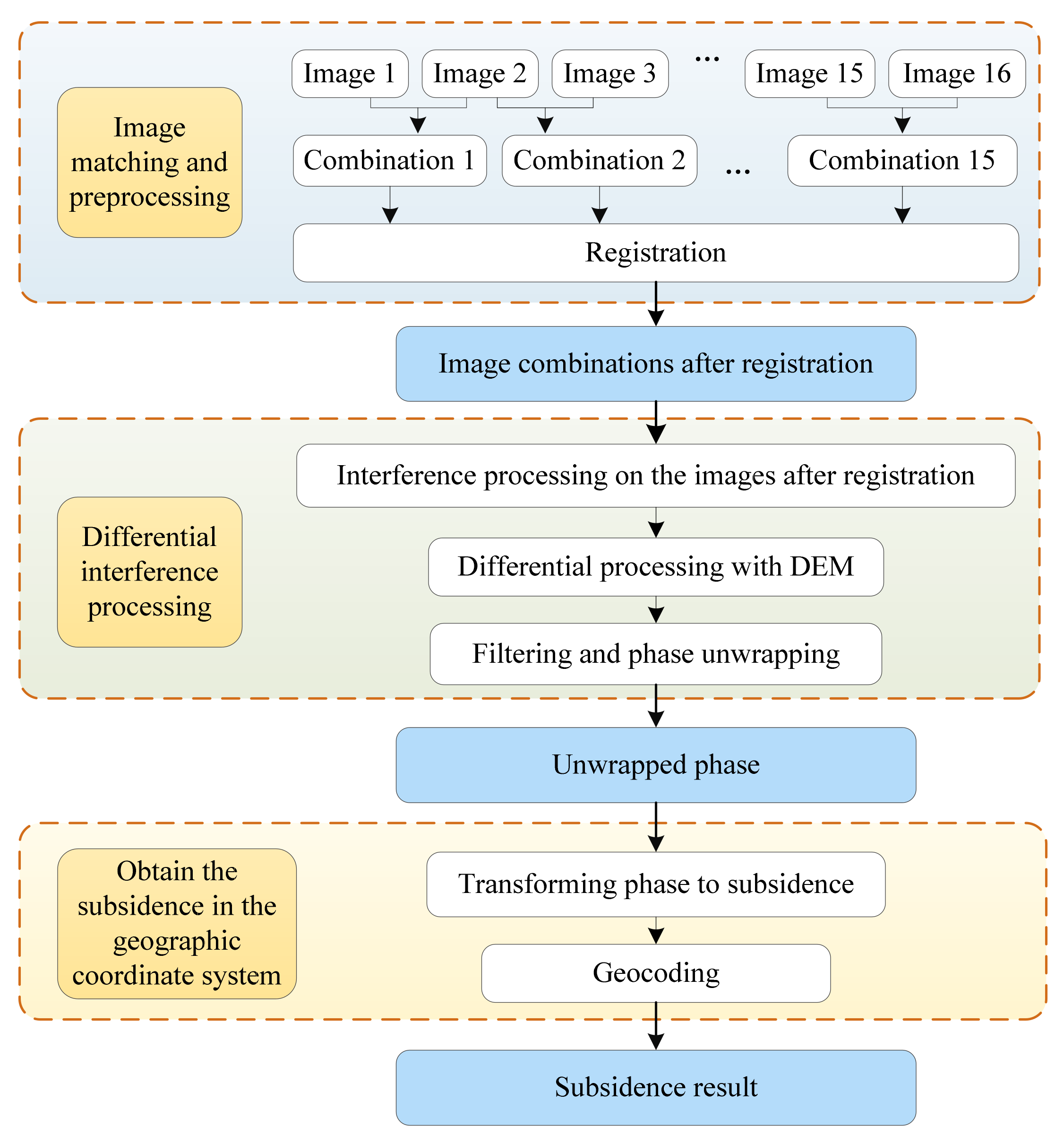
The basic principle of D-InSAR method is to generate an interferogram by conjugate multiplication of two radar complex images before and after deformation, remove topographical factors using the difference from the external DEM to generate a differential interferogram, and then to extract the deformation information of the ground targets from the differential interferogram [26]. In this study, 16 SAR images covering the mining area were used to obtain the mining subsidence by D-InSAR. The main steps are as follows:
(1) According to the imaging time order, the 16 SAR images were paired with the images of the nearest imaging time to form 15 combinations. The two SAR images in each combination were selected as the master image and the salve image, and the offset of the same name points was calculated to make the registration for the images.
(2) After conjugate multiplication of the registered images, interferograms were obtained, containing not only subsidence information, but also a series of noise phases, expressed as follows:
φ = φ f l a t + φ t o p o + φ d e f + φ a t m + φ n o i s e
As can be seen from Equation (1), the interferogram mainly includes the flat phase φ f l a t , the topographic phase φ t o p o , the deformation phase φ d e f , the atmospheric phase caused by ionospheric delay and tropospheric delay φ a t m and the noise phase φ n o i s e . To obtain the deformation phase, the other phase components must be removed and possible noise should be minimized.
(3) DEM was introduced to simulate the topographic phase and the flat phase. The simulated phases will differentiate the interferograms to remove the topographic phase and the flat phase. To suppress the influence of various noise on the quality of the interferograms, it was further filtered to obtain the deformation phase, which is bound between [ π , π ] due to the periodicity of trigonometric functions. The minimum cost flow (MCF) algorithm can obtain the better results when it is difficult to unwrap due to low coherence caused by mining large subsidence [27]. Therefore, the MCF algorithm was selected for further phase unwrapping to obtain the phase representing the real deformation, denoted by Δ R t o w .
Δ R t o w = ( λ / 4 π ) φ r e a l
The data processing by D-InSAR is shown in Figure 2.

2.3.2. SBAS-InSAR Subsidence Monitoring

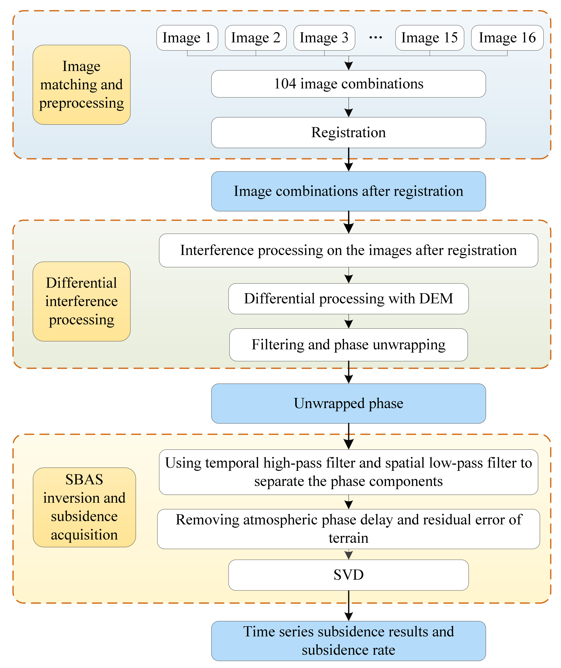
SBAS-InSAR is a time-series-monitoring method developed to solve the spatio-temporal decoherence encountered in D-InSAR. By limiting the spatial and temporal baseline, this method combines all the SAR images that meet the requirements in order to generate more interferograms and extract reliable results from them [28]. In this study, 16 SAR images covering the mining area were used to obtain the mining subsidence by SBAS-InSAR. The main steps are as follows.
(1) According to the small baseline principle, the vertical baselines between all SAR images should be controlled to be less than 800 m and the time baselines should be as small as possible. Considering the actual situation of the study area, the SAR image on 21 December 2015 was selected as the public master image (the only master image) and the other images were registered and sampled into the public master image as slave images [29]. Then, 104 combinations of images were formed to meet the data requirements of mining subsidence monitoring. In addition, the vertical baselines between each interference pair were all less than 200 m and the maximum time baseline was 348 days, in line with the principle of small baseline. Referring to the public master image, the remaining images were registered to the master image.
(2) By means of registration and conjugate multiplication, the SAR images generated interferograms that will difference with the external DEM to create 104 differential interferograms. Goldstein’s method was used to filter the differential interferograms to reduce the noise on them. Furthermore, the minimum coherence threshold selection method was used to select the points with stable phase characteristics in the 104 differential interferograms as high-coherence points, and the MCF algorithm was used to unwrap the phase of differential interferograms.
(3) The unwrapped differential interferograms included not only the deformation phase, but also atmospheric delay, DEM error and the noise phase. According to the different characteristics of the error phase in time and space, the phase of differential interferograms were separated to remove the atmospheric phase delay and residual topographic errors.
(4) The Singular Value Decomposition (SVD) method was used to extract the temporal surface subsidence from the unwrapped phase with all kinds of error removed [30,31]. The surface subsidence rate during the imaging period was also calculated and projected to the geographic coordinate system.
The data processing by SBAS-InSAR is shown in Figure 3.

3. Results

3.1. Overall Comparative Analysis of D-InSAR- and SBAS-InSAR-Monitored Results

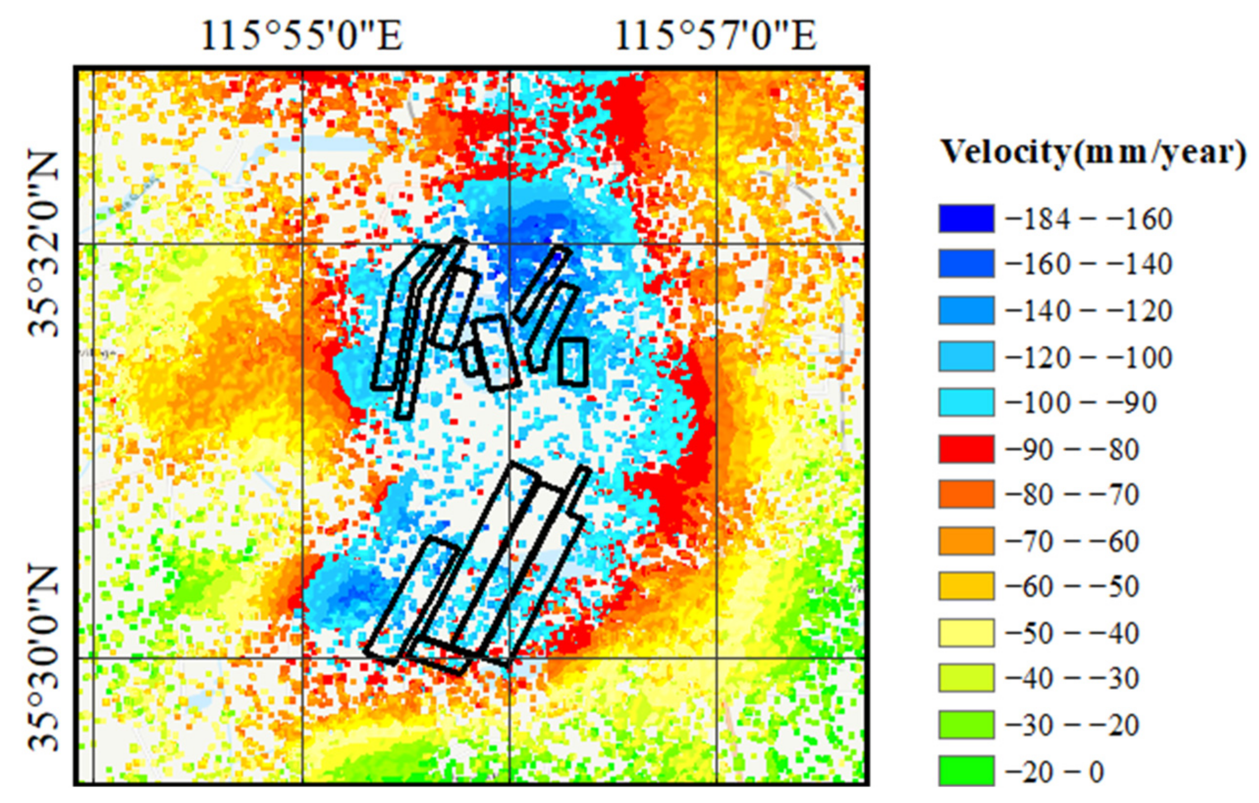
In this study, we took the monitored results on 23 August 2015 as the benchmark and sequentially accumulated D-InSAR-monitored results from 23 August 2015 to 3 December 2016, to compare with SBAS-InSAR results and the actual mining situation in the same period. Figure 4 shows the average annual subsidence rate of the mining area monitored by SBAS-InSAR. Figure 5 shows the comparison of D-InSAR and SBAS-InSAR-monitored results in the same period.
It is worth noting that, the longer the band of SAR image, the stronger its monitoring capacity, and the higher its coherence accordingly. C-band Sentinel-1A SAR images have shorter wavelength (5.6 cm). Theoretically, the coherence of them is lower than that of long band images. In addition, mining often produces large subsidence in a short time, which will cause decoherence. For these reasons, SBAS-InSAR is unable to select the high-coherence points in the mining subsidence center, which will cause information loss in the mining subsidence center.
Analysis of the surface subsidence results in Figure 4 and Figure 5 and the working face information in Figure 1 and Table 1 indicates the following.
(1) From 23 August 2015 to 3 December 2016, the mining subsidence basins monitored by D-InSAR and SBAS-InSAR methods had basically the same positions and temporal and spatial changes, which were highly consistent with those of actual working faces. With continuous mining, the mining subsidence center moved to the southwest direction and the subsidence range gradually expanded. There were different magnitudes of subsidence at the 13 working faces. In the northern mining area, working faces VI and XII had the most serious subsidence, with maximum average subsidence rates of 184 and 128 mm/year, respectively. In the southern mining area, working faces V and VII had more serious subsidence, with maximum average subsidence rates of 136 and 155 mm/year, respectively.
(2) From August to November 2015, working face VI in the north and V in the south of the mining area were being mined. Referring to Figure 5a, during this period, the range and amount of subsidence in the mining area monitored by D-InSAR and SBAS-InSAR methods were small. In the northern mining area, working face VI had the most serious subsidence, with the maximum cumulative subsidence of 163 and 79 mm detected by D-InSAR and SBAS-InSAR, respectively. In the southern mining area, the subsidence center was located at working face V. However, due to the weak mining intensity, the cumulative subsidence of this working face monitored by D-InSAR and SBAS-InSAR was, respectively, 121 and 90 mm, smaller than that of working face VI.
(3) From November 2015 to January 2016, in the northern mining area, the mining of working face VI was finished, while the mining of working face XII had not yet begun. At the same time, working face V in the southern mining area was being mined. Referring to Figure 5b, in January 2016, D-InSAR and SBAS-InSAR monitored continued subsidence at working face VI. This was because working face VI had just finished being mined and the surface was not yet stable. In addition, this working face was close to working faces II, IV, VIII, and IX, which had already been mined. The mining activities of VI disturbed the overlying strata, leading to groundwater loss and continuous subsidence of the surface, with maximum cumulative subsidence of 231 and 110 mm, monitored by D-InSAR and SBAS-InSAR, respectively. At the same time, because mining had ended in the northern mining area, the mining intensity of working face V in the southern mining area increased, resulting in increased subsidence. D-InSAR- and SBAS-InSAR-monitored maximum cumulative subsidence of this working face was 222 and 103 mm, respectively.
(4) From January to April 2016, in the northern mining area, mining of working face XII began. In the southern mining area, working face V continued to be mined, while mining of working face VII had not yet begun. Combined with the actual data, it can be seen that working face XII was near the river, resulting in higher water content in the rock layer. With the mining of working face XII, the adjacent rock layer had been disturbed and compressed, leading to the loss of water and sand in the aquifer and an increase in subsidence. Referring to Figure 5c, both D-InSAR and SBAS-InSAR monitored that the subsidence in the northern mining area had extended to the west during this period. However, due to the short mining time of working face XII, the subsidence center was still located at working face VI. In the south of the mining area, the subsidence change trend monitored by D-InSAR was also consistent with that by SBAS-InSAR. The results of D-InSAR and SBAS-InSAR methods show that the subsidence of working face V was accelerated due to groundwater loss, caused by continuous mining; the north-south fault zone in the west; and the river crossing in the south. Until April 2016, the maximum cumulative subsidence of this working face was 411 and 157 mm, monitored by D-InSAR and SBAS-InSAR, respectively.
(5) From April to August 2016, in the northern mining area, working face XII continued to advance while mining had begun two months earlier in working face XIV. In the southern mining area, mining began in working face VII, and working face V continued to advance to the north. Referring to Figure 5d, D-InSAR and SBAS-InSAR methods detected that the subsidence had extended to the south, which was consistent with the actual situation. From Figure 5e, it can be seen that working face V continued to be mined during this period, and adjacent to it working face VII began to be mined in April 2016. D-InSAR monitored that the subsidence range extended to the southwest, and SBAS-InSAR results also show this trend. Until August 2016, as per D-InSAR and SBAS-InSAR, the subsidence center was still located at working face V and the maximum cumulative monitored subsidence was 504 and 165 mm, respectively.
(6) From August to December 2016, in the northern mining area, mining finished in working face XII. In the southern mining area, working faces XVI and VII were still being mined, while mining ended in working face V. In the northern mining area, mining ended in working face XII in October 2016, but the surface was not stable, still sinking slowly. By December 2016, the subsidence in working faces VI and XII was the most serious; their maximum cumulative subsidence monitored by D-InSAR was 337 and 301 mm and by SBAS-InSAR was 224 and 164 mm, respectively. In the southern mining area, D-InSAR monitored that the subsidence range had expanded and the subsidence center had moved in the southwest direction, because mining had ended in working face V and started in working faces VII and XVI. The maximum cumulative subsidence monitored by D-InSAR was 517 mm. The SBAS-InSAR results also showed the same trend, with the maximum cumulative subsidence monitored as 218 mm.
(7) In conclusion, D-InSAR and SBAS-InSAR methods can accurately locate and detect the change trend in mining subsidence, consistent with the mining process of each working face in the mining area. In terms of processing, D-InSAR can only process two SAR images and obtain the subsidence results from them at a time. In order to obtain the time-series cumulative subsidence, it is necessary to repeat the D-InSAR processing many times, and then accumulate the subsidence results. SBAS-InSAR has the capability to process multiple images at a time. Therefore, compare with D-InSAR, SBAS-InSAR can generate subsidence results and the average subsidence rate of long time series more efficiently and conveniently. However, in the subsidence center with large subsidence, the monitoring capability of SBAS-InSAR is obviously insufficient, mainly because the subsidence in the mining area is too large in a short time, which can cause decoherence. At this time, SBAS-InSAR cannot select the stable high-coherence points, which leads to the loss of subsidence center information.

3.2. Overall Comparative Analysis of D-InSAR- and SBAS-InSAR-Monitored Results

3.2.1. D-InSAR-, SBAS-InSAR- and Leveling-Monitored Results

The mining period of working face V (September 2013 to August 2016) coincided with the time span of 16 Sentinel-1A SAR images (23 August 2015, to 3 December 2016) (Table 1). Therefore, we took working face V as an example to compare D-InSAR-, SBAS-InSAR-, and leveling-monitored results of subsidence. The surface of working face V with an average coal thickness of 3.35 m was covered with farmland. In addition, the dip line of working face V was 2800 m, with 55 leveling observation points (H1 to H55 from west to east). The strike line of working face V was 4600 m, with 111 leveling observation points (Z1 to Z111 from south to north). The layout of leveling observation points was shown in Figure 6.
Considering that SBAS-InSAR could not select stable high-coherence points in the subsidence center with large subsidence, leading to the information loss, the Kriging spatial interpolation was used to obtain the lost subsidence information. The cumulative subsidence monitored by D-InSAR and SBAS-InSAR, corresponding to the leveling observation points on the dip line and the strike line of working face V, was extracted. Based on the leveling-monitored results of the working face, the errors in InSAR results were calculated to verify the monitoring accuracy of D-InSAR and SBAS-InSAR methods. Table 3 shows the error statistics of InSAR-monitored results, and Figure 7 compares InSAR- and leveling-monitored results.
As can be seen from Table 3 and Figure 7, both D-InSAR and SBAS-InSAR could detect subsidence basins above working face V from 23 August 2015 to 3 December 2016. At the subsidence basin edges with small subsidence, the amounts and the rate of subsidence were small. Therefore, the coherence of this area was high, the InSAR-monitored results were consistent with leveling-monitored results and their subsidence curves had the same trends. In the subsidence basin center with large subsidence, the amounts and the rate of subsidence became larger, and the coherence in this area became lower, accordingly. For this reason, D-InSAR- and SBAS-InSAR-monitored results were not ideal in the subsidence basin center. Compared with the leveling-monitored results, the cumulative mean absolute errors in D-InSAR-monitored results on the dip line and the strike line were 203 and 349 mm and the maximum absolute errors were 659 and 923 mm, respectively. Due to the failure to select stable high-coherence points at the subsidence center, the results of SBAS-InSAR monitored were greatly different from that of leveling. Compared with the leveling-monitored results, the cumulative mean absolute errors in SBAS-InSAR-monitored results on the dip line and the strike line were 338 and 457 mm and the maximum absolute errors were 1049 and 1079 mm, respectively.

3.2.2. Division of Different Subsidence Magnitude in the Mining Area

To finely analyze the monitoring accuracy of D-InSAR and SBAS-InSAR methods, considering the technical characteristics of InSAR and the subsidence law of the mining area, the mining area was divided into three categories according to the subsidence magnitude: the subsidence edge area, the subsidence large area, and the subsidence center area. Then, the InSAR- and leveling -monitored results of the leveling observation points in different subsidence magnitude areas were compared and analyzed.
From the above analysis, it can be seen that the results of InSAR monitored at the subsidence edges are consistent with those of leveling. Therefore, the maximum subsidence that InSAR can monitor was taken as the judgment basis of the subsidence edge area. For the SAR image, to recover the subsidence information correctly, the shape variable of the same resolution unit must not exceed half its wavelength. Therefore, the maximum subsidence that can be monitored by temporal InSAR is
D = λ 2 ( n 1 )
where D represents the maximum subsidence that can be monitored by temporal InSAR, λ represents the radar wavelength, and n represents the number of images.
As can be seen from Table 2, the SAR images were obtained from 23 August 2015 to 3 December 2016. Due to the low coherence of the five images obtained from April to August, the remaining 11 images were selected to calculate the maximum subsidence that can be monitored by temporal InSAR based on Equation (3), which was 277 mm. Points with subsidence less than 277 mm were classified as the subsidence edge area.
For the subsidence basin of the mining area, the inflection point is the division of concave and convex change of the curve on the main section of the subsidence basin, which is usually half the maximum subsidence. Therefore, the inflection point of the subsidence basin was taken as the judgment basis of the subsidence center area. As per Figure 7, the maximum subsidence in the main section of the subsidence basin of the working face was 1180 mm, monitored by leveling. Therefore, the point with subsidence of 590 mm was seen as the inflection point of the subsidence basin in the classification. The points with subsidence between 277 and 590 mm were classified as points in the subsidence large area, and the points with subsidence between 590 and 1180 mm were classified as points in the subsidence center area.

3.2.3. Comparison of InSAR- and Leveling-Monitored Results with Different Subsidence Magnitudes

The InSAR-monitored results in areas with different subsidence magnitudes were verified by comparing them one by one with the corresponding leveling monitored results in order of subsidence severity from low to high.
(1) Subsidence edge area (subsidence less than 277 mm)
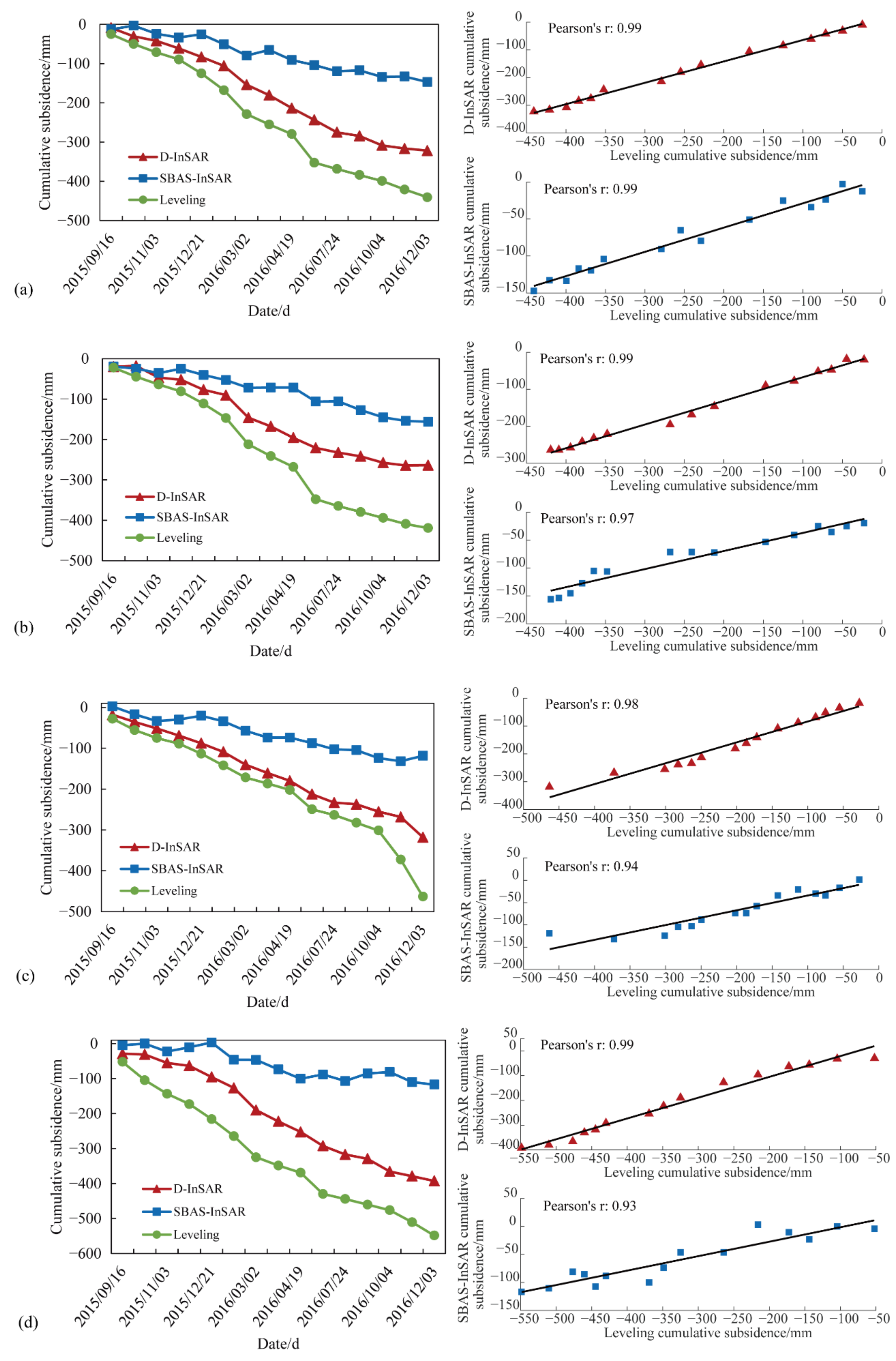
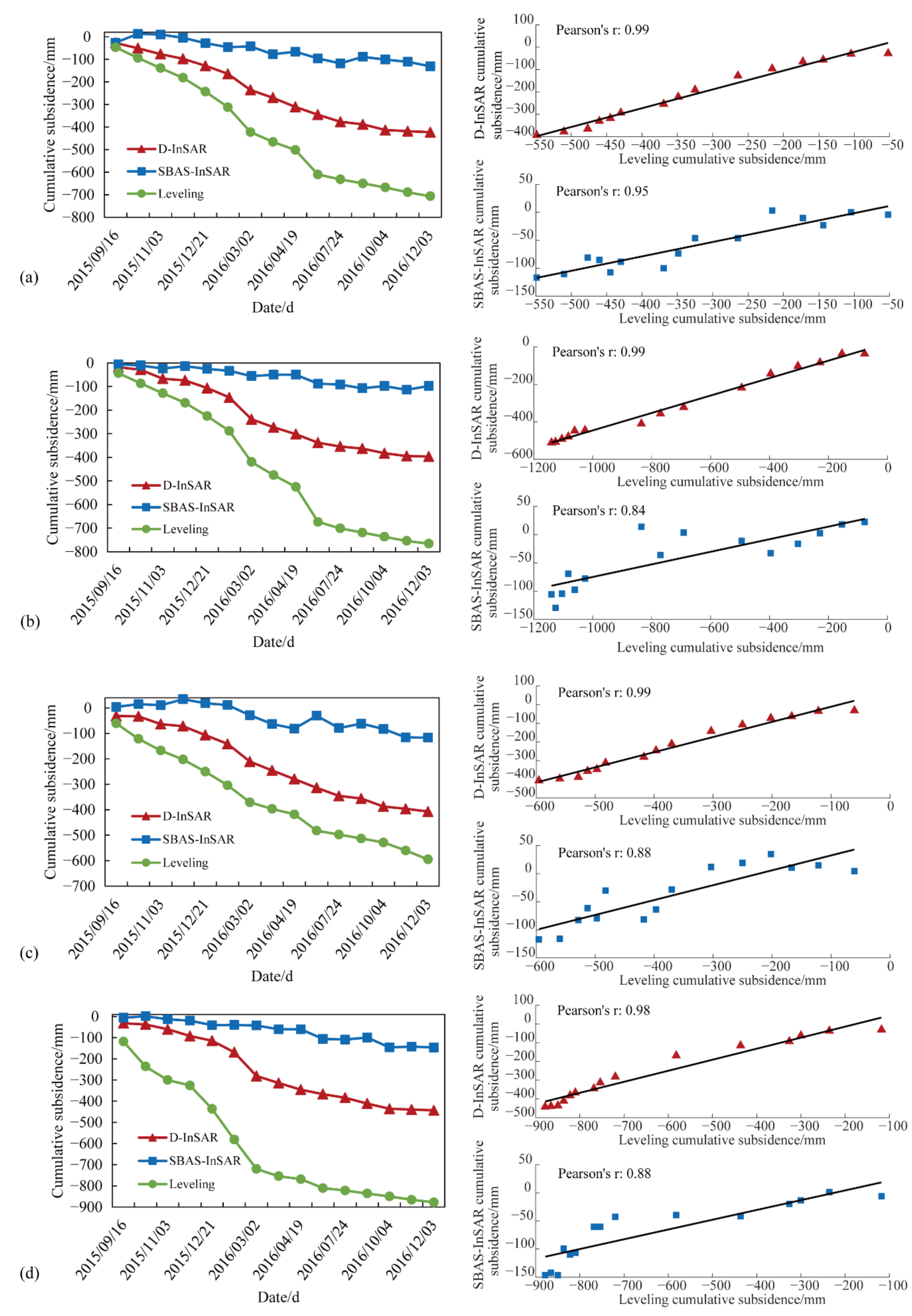
Referring to Figure 7, there were 56 leveling observation points, H1-H26, Z1-Z18, and Z100-Z111, in the subsidence edge area with small subsidence. At these points, the cumulative mean absolute errors in D-InSAR and SBAS-InSAR were 50 and 59 mm, respectively, compared with the leveling-monitored results. To make a more comprehensive comparison between InSAR- and leveling-monitored results, we also calculated the Pearson correlation coefficient between InSAR and leveling subsidence curves to judge whether their change trends were consistent. The higher the Pearson correlation coefficient, the stronger the linear relationship between them, reflecting the more consistent change trends. For the leveling observation points in the subsidence edge area, the average correlation coefficients between subsidence curves monitored by D-InSAR, SBAS-InSAR and leveling were 0.90 and 0.93, respectively. The comparison and correlation coefficients of subsidence curves monitored by the three techniques at some leveling observation points in the subsidence edge area are shown in Figure 8.
As can be seen from Figure 8, the leveling observation points H9, H18, H24, and Z14, located in the subsidence edge area, and their final cumulative subsidence monitored by leveling were 185, 208, 246, and 134 mm, respectively. A comparison of the subsidence curves monitored by InSAR and leveling at these four leveling observation points shows the high correlation between them. The correlation coefficients of D-InSAR- and leveling-monitored results at the four leveling observation points were 0.99, 0.99, 0.99, and 0.95, while the correlation coefficients of SBAS-InSAR- and leveling-monitored results were 0.98, 0.99, 0.99, and 0.96, respectively. The change trends in subsidence curves monitored by D-InSAR and SBAS-InSAR methods were consistent with that monitored by leveling, but the final cumulative subsidence monitored by the three methods was slightly different. The cumulative absolute errors in D-InSAR-monitored results at the four leveling observation points were 40, 52, 39, and 59 mm, while the cumulative absolute errors in SBAS-InSAR-monitored results were 66, 40, 92, and 47 mm, respectively, with a centimeter-level accuracy.
(2) Subsidence large area (subsidence between 277 and 590 mm)
Referring to Figure 7, there were 35 leveling observation points, H27-H32, H50-H55, Z19-Z23, Z52-Z63, and Z94-Z99, in the subsidence large area. At these points, the cumulative mean absolute errors in D-InSAR and SBAS-InSAR were 190 and 314 mm, respectively, compared with the leveling-monitored results. For the leveling observation points in the subsidence large area, the average correlation coefficients between subsidence curves monitored by D-InSAR, SBAS-InSAR and leveling were 0.97 and 0.94, respectively. The comparison and correlation coefficients of subsidence curves monitored by the three techniques at some leveling observation points in the subsidence edge area are shown in Figure 9.
As can be seen from Figure 9, the leveling observation points H30, H53, Z58, and Z63, located in the subsidence large area, and their final cumulative subsidence monitored by leveling were 441, 419, 463, and 549 mm, respectively. A comparison of subsidence curves monitored by D-InSAR and leveling at these four leveling observation points shows the high correlation between them, of 0.99, 0.99, 0.98 and 0.99, respectively. The change trends in subsidence curves monitored by the two were consistent. The subsidence curves of SBAS-InSAR had a slight difference with leveling in some periods, but the overall correlation between them was high and their change trends were basically consistent. The correlation coefficients between the two at the four leveling observation points were 0.99, 0.97, 0.94, and 0.93, respectively. In the subsidence large area, the amount of subsidence monitored by InSAR and leveling began to differ. The cumulative absolute errors in D-InSAR-monitored results at the four leveling observation points were 118, 155, 145, and 156 mm, while the cumulative absolute errors in SBAS-InSAR-monitored results were 294, 263, 344 and 432 mm, respectively.
(3) Subsidence center area (subsidence between 590 and 1180 mm)
Referring to Figure 7, there were 75 leveling observation points, H33-H49, Z24-Z51, and Z64-Z93, in the subsidence center area. At these points, the InSAR- and leveling-monitored results were quite different. The cumulative mean absolute errors in D-InSAR and SBAS-InSAR were 540 and 733 mm, respectively, compared with the leveling-monitored results. For the leveling observation points in the subsidence center area, the average correlation coefficients between subsidence curves monitored by D-InSAR, SBAS-InSAR and leveling were 0.97 and 0.90, respectively. The comparison and correlation coefficients of subsidence curves monitored by the three techniques at some leveling observation points in the subsidence edge area are shown in in Figure 10.
As can be seen from Figure 10, the leveling observation points H34, H41, Z72, and Z83, located in the subsidence center area, and their final cumulative subsidence monitored by leveling were 706, 765, 595 and 877 mm, respectively. A comparison of the subsidence curves monitored by InSAR and leveling at these four leveling observation points shows that the change trends in the two were basically consistent. The correlation coefficients of D-InSAR- and leveling-monitored results at the four leveling observation points were 0.99, 0.99, 0.99, and 0.98. SBAS-InSAR cannot select stable high-coherence points at the subsidence center, so its monitoring capacity is insufficient there. Although the subsidence curves monitored by SBAS-InSAR showed downward trends as a whole, they were quite different from the leveling, and even opposite to the leveling, in individual periods. The correlation coefficients of the two at the four leveling observation points were 0.95, 0.84, 0.88, and 0.88. A comparison of cumulative subsidence monitored by InSAR and leveling shows little difference between the three in the initial monitoring period, and the difference increases with increasing subsidence. As of 3 December 2016, the InSAR results could not reflect the true situation. The cumulative absolute errors in D-InSAR monitored results at the four leveling observation points were 283, 369, 188, and 434 mm, while the cumulative absolute errors in SBAS-InSAR-monitored results were 575, 668, 478 and 730 mm, respectively.
An analysis of (1) to (3) leads to the conclusion that in the subsidence edge area (subsidence less than 277 mm), the Pearson correlation coefficients of D-InSAR and leveling subsidence curves and those of SBAS-InSAR and leveling subsidence curves were both very high, showing a strong linear relationship, reflecting that the subsidence change trends monitored by D-InSAR and SBAS-InSAR were highly consistent with that by leveling. In the subsidence edge area, D-InSAR and SBAS-InSAR could detect the accurate change trends and amounts of mining subsidence, consistent with leveling. In the subsidence large area (subsidence between 277 and 590 mm), the change trends in the subsidence curves monitored by the two InSAR techniques were basically consistent with leveling, but their subsidence amounts began to differ from leveling-monitored results. In the subsidence center area (subsidence between 590 and 1180 mm), the Pearson correlation coefficients of D-InSAR and leveling subsidence curves were still very high. However, the Pearson correlation coefficients of SBAS-InSAR and leveling subsidence curves became smaller, the linear relationship between them became weaker. It reflected that D-InSAR could still reflect the real subsidence change trend. However, the subsidence change trend monitored by SBAS-InSAR was not obvious, and the subsidence amounts monitored by this method were quite different from the leveling, which could not reflect the actual situation.

4. Correction

The comparative analysis of InSAR- and leveling-monitored results shows that InSAR-monitored errors were closely related to the subsidence amount, which was related to the distance from the leveling observation point to the subsidence center on the rock movement observation line. The closer the leveling observation point was to the subsidence center, the greater was the subsidence, the smaller was the Pearson correlation coefficient between InSAR- and leveling-monitored results, and the greater were the errors. Therefore, this study established the relationship between the distance from the leveling observation point to the subsidence center and InSAR-monitored errors and then modified the InSAR-monitored results according to the relationship to improve the accuracy of the InSAR results. The specific steps are as follows.

4.1. Fitting Curves of Leveling- and InSAR-Monitored Errors

According to the previous analysis, there were two subsidence basins in working face V and their geological conditions and mining conditions were basically the same. Thus, in order to improve the calculation efficiency, this experiment took the leveling observation point Z89 as the subsidence center point and only took the northern subsidence basin with sufficient leveling observation points as the research area, establishing the relationship between the distance from the leveling observation point on the dip and strike lines to the subsidence center and InSAR-monitored errors. According to the law of underground rock strata and surface movement in the mining area, the rock strata movement caused by mining approximately obeys the Gaussian distribution, and the comparison between InSAR- and leveling-monitored results in Figure 7 also conforms to this law [32]. From this reason, we used a Gaussian curve to fit the relationship between the distance from the leveling observation point to the subsidence center point and D-InSAR- and SBAS-InSAR-monitored errors. The fitting curves between leveling- and InSAR-monitored errors on the dip and strike lines are shown in Figure 11, and the fitting relationships of D-InSAR- and SBAS-InSAR-monitored errors are shown in Equations (4) and (5), respectively.
Q D - InSAR ( d ) = 737 . 9 exp d + 105.8 388 2 Z D - InSAR ( d ) = 600 . 4 exp d 82.86 497.3 2
Q SBAS - InSAR ( d ) = 1131 exp d + 84.2 400.2 2 Z SBAS - InSAR ( d ) = 818 . 3 exp d 52.16 542.3 2
where D represents the distance from the leveling observation point to the subsidence center point; Q D - InSAR ( d ) and Z D - InSAR ( d ) , respectively, represent the errors in D-InSAR-monitored results after fitting on the dip and strike lines; and Q SBAS - InSAR ( d ) patio Z SBAS - InSAR ( d ) , respectively, represent the errors in SBAS-InSAR-monitored results after fitting on the dip and strike lines.

4.2. Relationship between Leveling and InSAR-Monitored Errors

Figure 11 shows that the change trends in fitting curves between leveling- and InSAR-monitored errors on the dip line were not completely consistent with those on the strike line. This is mainly because the working face was mined along the strike direction and there was a phenomenon of subsidence lag in this direction, resulting in inconsistent subsidence trends in dip and strike. To more accurately correct the InSAR-monitored results, this study comprehensively considered the subsidence changes in two directions and weighted averaged fitting curves on the dip and strike lines between the distance from the leveling observation point to the subsidence center and InSAR-monitored errors. Then, the final correction relationship can be determined.
The cumulative mean square deviation of D-InSAR-monitored results of leveling observation points on the dip and strike lines were 290 and 412 mm, respectively, and the cumulative mean square deviation of SBAS-InSAR-monitored results of leveling observation points on the dip and strike lines were 480 and 556 mm, respectively. According to
P dip P strike = σ stirke 2 σ dip 2
it can be calculated that P D - InSAR - dip = 0.67 , P D - InSAR - strike = 0.33 , P SBAS - InSAR - dip = 0.57 , and P SBAS - InSAR - strike = 0.43 . The relationship between the distance from the leveling observation point to the subsidence center and the InSAR monitored errors can be expressed as
F D - InSAR ( d ) = 0.67 Q D - I n S A R ( d ) + 0.33 Z D - I n S A R ( d ) = 494.393 exp d + 105.8 388 2 + 198.132 exp d 82.86 497.3 2
F SBAS - InSAR ( d ) = 0.57 Q SBAS - InSAR ( d ) + 0.43 Z SBAS - InSAR ( d ) = 644.67 exp d + 84.2 400.2 2 + 351.869 exp d 52.16 542.3 2
where F D - InSAR ( d ) and F SBAS - InSAR ( d ) , respectively, represent the weighted errors in D-InSAR- and SBAS-InSAR-monitored results.

4.3. Correction of InSAR Monitored Results

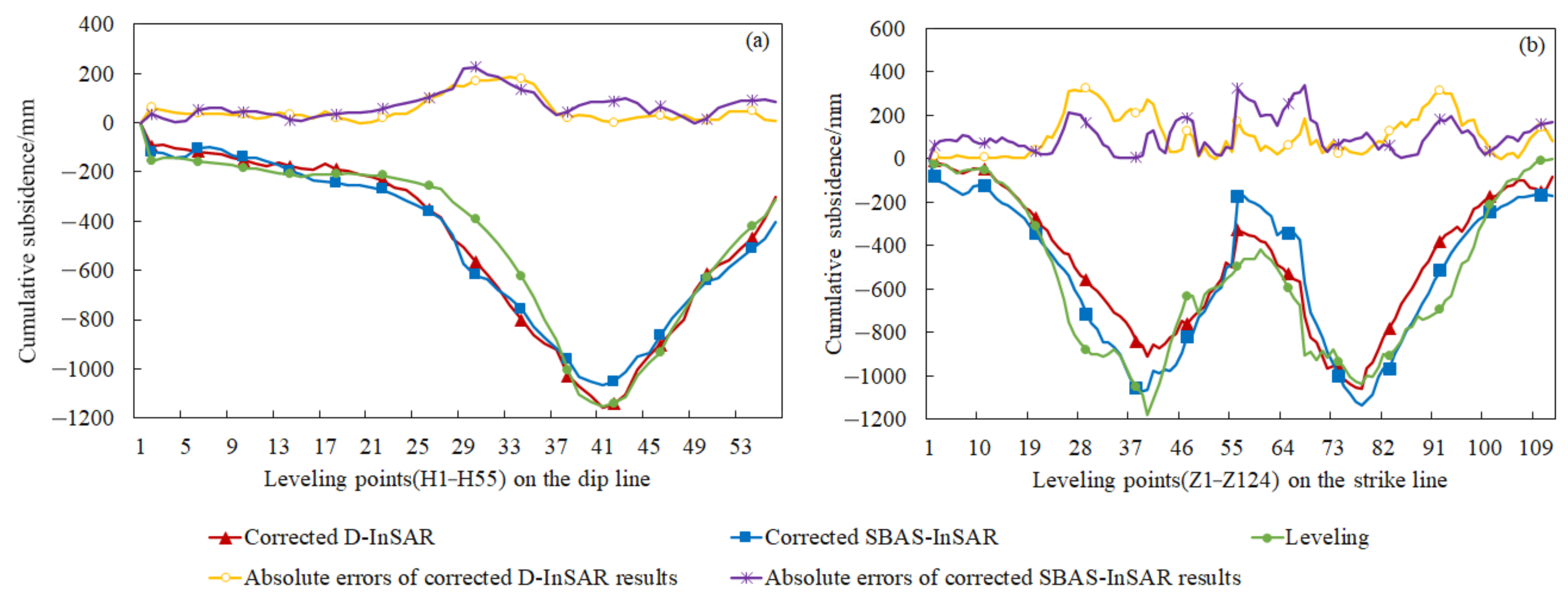
According to Equations (7) and (8), D-InSAR- and SBAS-InSAR-monitored results corresponding to leveling observation points on the dip and strike lines were corrected and the errors between them and leveling were calculated, as shown in Table 4. Figure 12 shows the comparison between the corrected InSAR- and leveling-monitored results.
By analyzing Table 4 and Figure 12, it can be seen that the change trends in the corrected InSAR subsidence curves were consistent with those of leveling, and their degree coincidence was higher. For the corrected D-InSAR-monitored results, the cumulative mean absolute error, the root mean square error, the maximum absolute error, and the absolute error at the maximum subsidence point were 52, 75, 187 and 9 mm on the dip line and 106, 144, 324 and 271 mm on the strike line, respectively. Compared with D-InSAR-monitored results before correction, the corrected results were increased by 74%, 74%, 72%, and 98% on the dip line and by 70%, 67%, 65%, and 71% on the strike line. For the corrected SBAS-InSAR-monitored results, the four kinds of errors were 71, 89, 227, and 84 mm on the dip line, and 106, 131, 338, and 114 mm on the strike line, respectively. Compared with SBAS-InSAR-monitored results before correction, the corrected results increased by 79%, 81%, 78%, and 92% on the dip line, and by 77%, 76%, 69%, and 89% on the strike line. The overall accuracy of the corrected InSAR-monitored results had improved. The corrected InSAR can not only obtain accurate subsidence edges but also monitor the subsidence center consistent with the leveling-monitored results, which can better reflect the actual situation.

5. Discussion

The experimental results show that the monitoring capabilities of D-InSAR and SBAS-InSAR were different in areas with different subsidence amounts in the mining area. The D-InSAR- and SBAS-InSAR-monitored results became more consistent with leveling-monitored results when the amounts and the rate of subsidence were smaller. At the subsidence basin edges with small subsidence, D-InSAR and SBAS-InSAR could better reflect the temporal and spatial change trend of subsidence with higher accuracy. In the subsidence basin center with large subsidence, the temporal and spatial change trend of D-InSAR-monitored subsidence was basically consistent with the leveling-monitored results, and the monitored subsidence amounts were quite less than the leveling-monitored subsidence amounts. However, SBAS-InSAR could not select the high-coherence points or the monitored subsidence amounts were quite less than those obtained by leveling monitoring, and it could not reflect the real temporal and spatial change trend and amounts of subsidence.
In order to solve the above problem that D-InSAR and SBAS-InSAR-monitored results were quite less than those of leveling monitoring in the subsidence center, this paper established the relationship between the distance from the leveling points to the subsidence center and the InSAR-monitored errors and corrected the InSAR-monitored results. This proposed method had both advantages and disadvantages. The method could effectively improve the InSAR-monitored results, and the corrected results were more consistent with leveling-monitored results. However, it requires the assistance of a small amount of leveling data, which is easy to be limited by actual situation. How to break through the constraints of terrestrial measurements and effectively improve InSAR-monitored capacity has an important research significance.
Future research may help to overcome the disadvantages of the proposed method. For example, using recovery technology of decoherent phase to recover the lost phase and obtain accurate subsidence; combining InSAR and the large gradient subsidence monitoring method to improve the monitoring accuracy of InSAR and break through the constraints of terrestrial measurements, and further improve the research of this paper.

6. Conclusions

Taking a mining area in Shandong Province, China, as the study area, we compared and analyzed the mining monitoring accuracy of D-InSAR and SBAS-InSAR based on the mining information and leveling monitored results. Furthermore, we established the relationship between the leveling observation point to the subsidence center point and the InSAR-monitored errors and corrected InSAR-subsidence-monitored results using this relationship. The main conclusions are as follows.
(1) Both D-InSAR and SBAS-InSAR can be used as effective methods for real-time monitoring of mining subsidence. D-InSAR and SBAS-InSAR methods can accurately detect the location, spatial distribution, and scope of subsidence in the mining area. Their monitored spatial change trends in the subsidence were consistent with the mining progress of the working faces.
(2) In the subsidence edge area, D-InSAR and SBAS-InSAR can obtain accurate mining subsidence information and the subsidence curves monitored by them were consistent with leveling. The average correlation coefficients between their monitored results and leveling were 0.90 and 0.93. The cumulative average absolute errors in the two InSAR monitored-results were 50 and 59 mm, respectively. In the subsidence large area, the subsidence curves monitored by D-InSAR and SBAS-InSAR methods were basically consistent with the leveling but the subsidence amount monitored by them began to differ from leveling. The average correlation coefficients between their monitored results and leveling were 0.97 and 0.94. The cumulative average absolute errors in the two InSAR-monitored results were 190 and 314 mm, respectively. In the subsidence center area, D-InSAR can still reflect the real subsidence trend but the subsidence change monitored by SBAS-InSAR was not obvious, which easily leads to a subsidence cavity. The average correlation coefficients between their monitored results and leveling were 0.97 and 0.90. The cumulative average absolute errors in the two InSAR-monitored results were 540 and 733 mm, respectively.
(3) The overall accuracy of InSAR results after correction had improved, better reflecting the actual situation. For corrected D-InSAR-monitored results, compared with the results before correction, the monitoring accuracy improved by 74%, 74%, 72%, and 98% on the dip line and 9.

Author Contributions

Conceptualization, S.Y. and G.L.; methodology, Y.C. and Q.T.; Data preprocessing, L.W. and F.W.; formal analysis, Y.C.; writing—original draft preparation, Y.C.; writing—review and editing, S.Y. and Y.C. All authors have read and agreed to the published version of the manuscript.

Funding

This research was funded by the National Natural Science Foundation of China, grant number 42074009 and 41404003; the Shandong Natural Science Foundation, grant number ZR2020MD044 and ZR2020MD043.

Institutional Review Board Statement

Not applicable.

Informed Consent Statement

Not applicable.

Data Availability Statement

The base data used for this study are available in publicly accessible web links: https://search.asf.alaska.edu/ (accessed on 26 October 2021) and https://earthexplorer.usgs.gov/ (accessed on 26 October 2021).

Acknowledgments

The authors wish to thank the European Space Agency (ESA) for supplying the free Sentinel-1A SAR data and NASA for providing the SRTM3 DEM data.

Conflicts of Interest

The authors declare no conflict of interest.

References

  1. Zebker, H.A.; Villasenor, J. Decorrelation in interferometric radar echoes. IEEE Trans. Geosci. Remote Sens. 1992, 30, 950–959. [Google Scholar] [CrossRef] [Green Version]
  2. Zhou, D.W.; Qi, L.Z.; Zhang, D.M.; Zhou, B.H.; Guo, L.L. Unmanned Aerial Vehicle (UAV) Photogrammetry Technology for Dynamic Mining Subsidence Monitoring and Parameter Inversion: A Case Study in China. IEEE Access 2020, 8, 16372–16386. [Google Scholar] [CrossRef]
  3. Chang, M.; Liu, Y.; Zhou, C.; Che, H.X. Hazard assessment of a catastrophic mine waste debris flow of Hou Gully, Shimian, China. Eng. Geol. 2020, 275, 105733. [Google Scholar] [CrossRef]
  4. Wang, L.Y.; Deng, K.Z.; Zheng, M.N. Research on ground deformation monitoring method in mining areas using the probability integral model fusion D-InSAR, sub-band InSAR and offset-tracking. Int. J. Appl. Earth Obs. Geoinf. 2019, 85, 101981. [Google Scholar] [CrossRef]
  5. Yang, Z.F.; Li, Z.W.; Zhu, J.J.; Yi, H.W.; Feng, G.C.; Hu, J.; Wu, L.X.; Preusse, A.; Wang, Y.J.; Papst, M. Locating and defining underground goaf caused by coal mining from space-borne SAR interferometry. ISPRS J. Photogramm. Remote Sens. 2018, 135, 112–126. [Google Scholar] [CrossRef]
  6. Klein, E.; Vigny, C.; Fleitout, L.; Grandin, R.; Jolivet, R.; Rivera, E.; Métois, M. A comprehensive analysis of the Illapel 2015 Mw8.3 earthquake from GPS and InSAR data. Earth Planet. Sci. Lett. 2017, 469, 123–134. [Google Scholar] [CrossRef] [Green Version]
  7. Acosta, G.; Rodríguez, A.; Euillades, P.; Euillades, L.; García, H. Detection of active landslides by DInSAR in Andean Precordillera of San Juan, Argentina. J. S. Am. Earth Sci. 2021, 108, 103205. [Google Scholar] [CrossRef]
  8. Novellis, D.V.; Castaldo, R.; Luca, C.D.; Pepe, S.; Zinno, I.; Casu, F.; Lanari, R.; Solaro, G. Source modelling of the 2015 Wolf volcano (Galápagos) eruption inferred from Sentinel 1-A DInSAR deformation maps and pre-eruptive ENVISAT time series. J. Volcanol. Geotherm. Res. 2017, 344, 246–256. [Google Scholar] [CrossRef]
  9. Budetta, P.; Nappi, M.; Santoro, S.; Scalese, G. DinSAR monitoring of the landslide activity affecting a stretch of motorway in the Campania region of Southern Italy. Transp. Res. Procedia 2020, 45, 285–292. [Google Scholar] [CrossRef]
  10. Tzampoglou, P.; Loupasakis, C. Evaluating geological and geotechnical data for the study of land subsidence phenomena at the perimeter of the Amyntaio coalmine, Greece. Int. J. Min. Sci. Technol. 2018, 28, 601–612. [Google Scholar] [CrossRef]
  11. Chen, B.Q.; Li, Z.H.; Chen, Y.; Fairbairn, D.; Kang, J.R.; Hu, J.S.; Liang, L. Three-dimensional time-varying large surface displacements in coal exploiting areas revealed through integration of SAR pixel offset measurements and mining subsidence model. Remote Sens. Environ. 2020, 240, 111663. [Google Scholar] [CrossRef]
  12. Ren, H.R.; Feng, X.M. Calculating vertical deformation using a single InSAR pair based on singular value decomposition in mining areas. Int. J. Appl. Earth Obs. Geoinf. 2020, 92, 102115. [Google Scholar] [CrossRef]
  13. Du, Y.L.; Yan, S.Y.; Yang, H.N.; Jiang, J.X.; Zhao, F. Investigation of deformation patterns by DS-InSAR in a coal resource-exhausted region with spaceborne SAR imagery. J. Asian Earth Sci. 2021, 5, 100049. [Google Scholar] [CrossRef]
  14. Liu, Z.G.; Bian, Z.F.; Lv, F.X.; Dong, B.Q. Monitoring on subsidence due to repeated excavation with D-InSAR technology. Int. J. Min. Sci. Technol. 2013, 23, 173–178. [Google Scholar] [CrossRef]
  15. Zhang, L.L.; Cai, X.X.; Wang, Y.; Wei, W.; Liu, B.; Jia, S.L.; Pang, T.F.; Bai, F.Z.; Wei, Z.M. Long-term ground multi-level deformation fusion and analysis based on a combination of deformation prior fusion model and OTD-InSAR for longwall mining activity. Measurement 2020, 161, 107911. [Google Scholar] [CrossRef]
  16. Modeste, G.; Doubre, C.; Masson, F. Time evolution of mining-related residual subsidence monitored over a 24-year period using InSAR in southern Alsace, France. Int. J. Appl. Earth Obs. Geoinf. 2021, 102, 102392. [Google Scholar] [CrossRef]
  17. Ghzala, K.; Tounsi, Y.; Muhire, D.; Nassim, A. Land motion detection in central Rwanda using small baseline subset interferometry. Remote Sens. Appl. Soc. Environ. 2021, 21, 100430. [Google Scholar] [CrossRef]
  18. Yalvac, S. Validating InSAR-SBAS results by means of different GNSS analysis techniques in medium- and high-grade deformation areas. Environ. Monit. Assess. 2020, 192, 1–12. [Google Scholar] [CrossRef]
  19. Wei, T.; Mahdi, M.; Wei, Z. Monitoring active open-pit mine stability in the Rhenish coalfields of Germany using a coherence-based SBAS method. Int. J. Appl. Earth Obs. Geoinf. 2020, 93, 102217. [Google Scholar] [CrossRef]
  20. Miranda, S.F.; Hernández-Madrigal, V.M.; Tuxpan-Vargas, J.; Reyes, C.I.V. Evolution assessment of structurally-controlled differential subsidence using SBAS and PS interferometry in an emblematic case in Central Mexico. Eng. Geol. 2020, 279, 105860. [Google Scholar] [CrossRef]
  21. Du, Z.Y.; Ge, L.L.; Ng, A.H.M.; Zhu, Q.G.Z.; Horgan, F.G.; Zhang, Q. Risk assessment for tailings dams in Brumadinho of Brazil using InSAR time series approach. Sci. Total. Environ. 2020, 717, 137125. [Google Scholar] [CrossRef]
  22. Carlà, T.; Farina, P.; Intrieri, E.; Hakki, K.; Casagli, N. Integration of ground-based radar and satellite InSAR data for the analysis of an unexpected slope failure in an open-pit mine. Eng. Geol. 2018, 235, 39–52. [Google Scholar] [CrossRef]
  23. Luo, H.B.; Li, Z.H.; Chen, J.J.; Pearson, C.; Wang, M.M.; Lv, W.C.; Ding, H.Y. Integration of Range Split Spectrum Interferometry and conventional InSAR to monitor large gradient surface displacements. Int. J. Appl. Earth Obs. Geoinf. 2018, 74, 130–137. [Google Scholar] [CrossRef] [Green Version]
  24. Gama, F.F.; Cantone, A.; Mura, J.C.; Pasquali, P.; Paradella, W.R.; Dos-Santos, A.R.; Silva, G.G. Monitoring subsidence of open pit iron mines at Carajás Province based on SBAS interferometric technique using TerraSAR-X data. Remote Sens. Appl. Soc. Environ. 2017, 8, 199–211. [Google Scholar] [CrossRef]
  25. Pillot, B.; Muselli, M.; Poggi, P.; Haurant, P.; Dias, J.B. Development and validation of a new efficient SRTM DEM-based horizon model combined with optimization and error prediction methods. Sol. Energy 2016, 129, 101–115. [Google Scholar] [CrossRef] [Green Version]
  26. Massonnet, D.; Rossi, M.; Carmona, C.; Adragna, F.; Peltzer, G.; Feigl, K.; Rabaute, T. The displacement field of the Landers earthquake mapped by rader interferometry. Nature 1993, 364, 138–142. [Google Scholar] [CrossRef]
  27. Jiang, T.C. Ameliorative Minimum Cost Flow Algorithm for Phase Unwrapping. Procedia Environ. Sci. 2011, 10, 2560–2566. [Google Scholar] [CrossRef] [Green Version]
  28. Sabrian, P.G.; Saepuloh, A.; Kashiwaya, K.; Koike, K. Combined SBAS-InSAR and geostatistics to detect topographic change and fluid paths in geothermal areas. J. Volcanol. Geotherm. Res. 2021, 416, 107272. [Google Scholar] [CrossRef]
  29. Rodriguez, E.; Martin, J.M. Theory and design of interferometric synthetic aperture radars. IEE Proc. Radar 1992, 139, 147–159. [Google Scholar] [CrossRef]
  30. Tao, Q.X.; Ding, L.J.; Hu, L.Y.; Chen, Y.; Liu, T.W. The performance of LS and SVD methods for SBAS InSAR deformation model solutions. Int. J. Remote Sens. 2020, 41, 8547–8572. [Google Scholar] [CrossRef]
  31. Vu, T.; Chunikhina, E.; Raich, R. Perturbation expansions and error bounds for the truncated singular value decomposition. Linear Algebra Appl. 2021, 627, 94–139. [Google Scholar] [CrossRef]
  32. Liu, B.C.; Dai, H.Y. Research development and origin of Probability Integral Method. J. Min. Strat. Control. Eng. 2016, 21, 1–3. [Google Scholar]
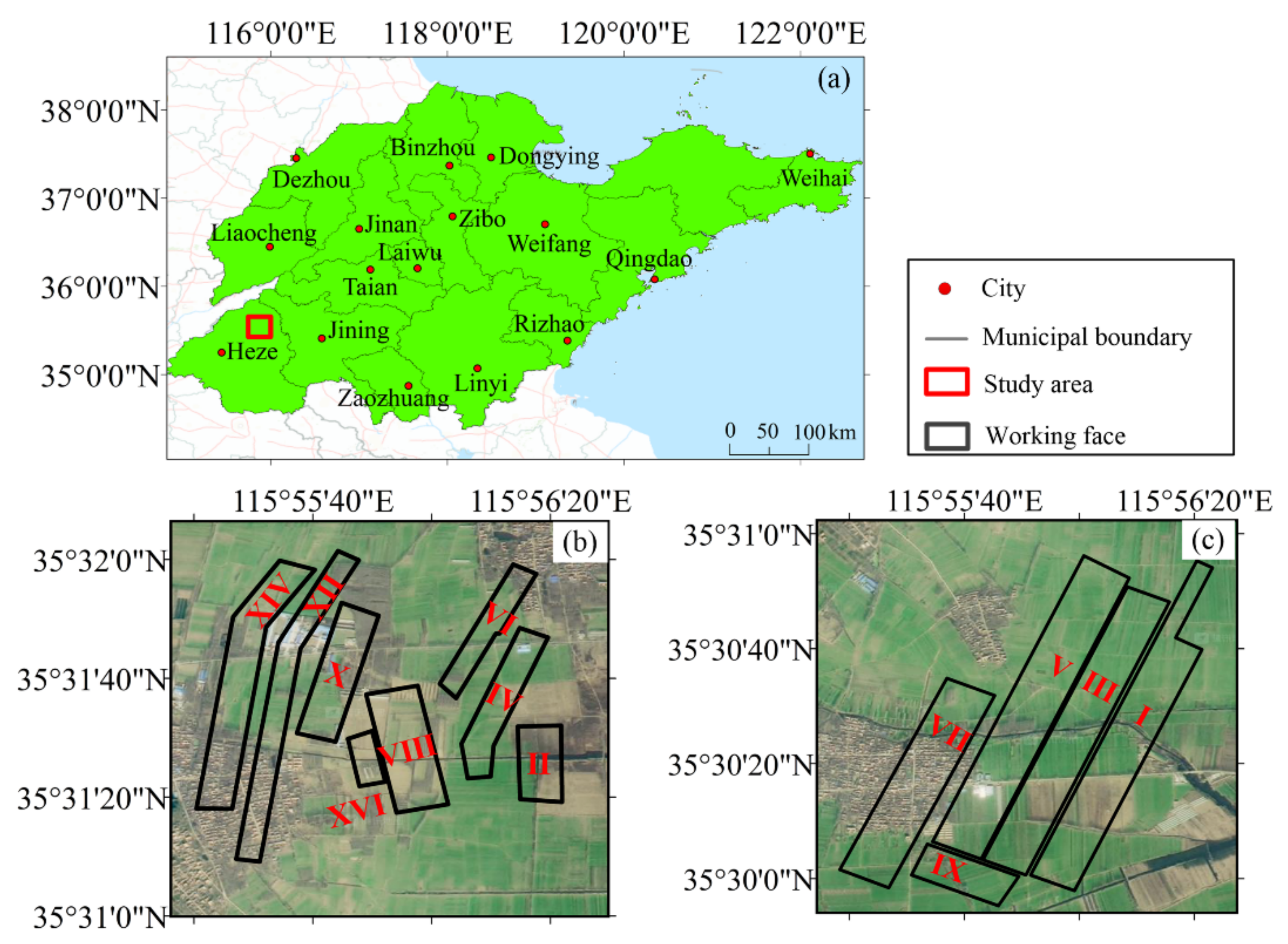
Figure 1. Geographical location and scope of the mining area: (a) location of the mining area, (b) positions of the working surfaces in the northern mining area, and (c) positions of the working surfaces in the southern mining area.
Remotesensing 13 04365 g001
Figure 2. Data processing by D-InSAR.
Remotesensing 13 04365 g002
Figure 3. Data processing by SBAS-InSAR.
Remotesensing 13 04365 g003
Figure 4. The average annual subsidence rate of the mining area monitored by SBAS-InSAR.
Remotesensing 13 04365 g004
Figure 5. The comparison of D-InSAR and SBAS-InSAR-monitored results during the same period.
Remotesensing 13 04365 g005
Figure 6. Layout of leveling observation points.
Remotesensing 13 04365 g006
Figure 7. Comparison between InSAR- and leveling-monitored results: (a) dip line and (b) strike line.
Remotesensing 13 04365 g007
Figure 8. Comparison and correlation coefficients of subsidence curves monitored by D-InSAR, SBAS-InSAR and leveling: (a) point H9, (b) point H18, (c) point H24, and (d) point Z14.
Remotesensing 13 04365 g008
Figure 9. Comparison and correlation coefficients of subsidence curves monitored by D-InSAR, SBAS-InSAR and leveling: (a) point H30, (b) point H53, (c) point Z58 and (d) point Z63.
Remotesensing 13 04365 g009
Figure 10. Comparison and correlation coefficients of subsidence curves monitored by D-InSAR, SBAS-InSAR and leveling: (a) point H34, (b) point H41, (c) point Z72 and (d) point Z83.
Remotesensing 13 04365 g010
Figure 11. The fitting curves between the distance from the leveling observation point to the subsidence center and InSAR-monitored errors: (a) D-InSAR fitting curve on the dip line; (b) D-InSAR fitting curve on the strike line; (c) SBAS-InSAR fitting curve on the dip line; (d) SBAS-InSAR fitting curve on the strike line.
Remotesensing 13 04365 g011
Figure 12. The comparison between the corrected InSAR- and leveling-monitored results: (a) dip line and (b) strike line.
Remotesensing 13 04365 g012
Table 1. Mining information for the working faces.
NoStrike Length/mDip Length/mMining PeriodNoStrike Length/mDip Length/mMining Period
I18002002010/11–2013/01VIII5732232011/07–2012/03
II4001902010/01–2010/06IX7701712012/12–2013/08
III20702102012/06–2015/08X18001022014/12–2015/06
IV8001302010/09–2011/03XII13501432016/01–2016/10
V18232242013/09–2016/08XIV2431072016/04–2016/06
VI6901102015/02–2015/11XVI1853802016/10–2017/01
VII11502402016/04 to present
Table 2. The specific parameters of SAR images.
NoImaging DateOrbitNoImaging DateOrbit
12015/08/23738992016/03/2610,539
22015/09/167739102016/04/1910,889
32015/10/108089112016/06/3011,939
42015/11/038439122016/07/2412,289
52015/11/278789132016/08/2912,814
62015/12/219139142016/10/0413,339
72016/01/149489152016/11/0913,864
82016/03/0210,189162016/12/0314,214
Table 3. The error statistics of InSAR-monitored results.
Cumulative Mean Absolute Error/mmCumulative Root Mean Square Error/mmCumulative Maximum Absolute Error/mmCumulative Absolute Error at Maximum Settlement Point/mm
D-InSARDip line203291659643
Strike line349433923923
SBAS-InSARDip line33848010491049
Strike line45755010791079
Table 4. Error statistics of corrected InSAR-monitored results.
Cumulative Mean Absolute Error/mmCumulative Root Mean Square Error/mmCumulative Maximum Absolute Error/mmCumulative Absolute Error at Maximum Settlement Point/mm
Corrected
D-InSAR
Dip line52751879
Strike line106144324271
Corrected SBAS-InSARDip line718922784
Strike line106131338114
Publisher’s Note: MDPI stays neutral with regard to jurisdictional claims in published maps and institutional affiliations.