Article

Onboard Digital Beamformer with Multi-Frequency and Multi-Group Time Delays for High-Resolution Wide-Swath SAR

1
College of Information Engineering, Inner Mongolia University of Technology, Hohhot 010080, China
2
Inner Mongolia Key Laboratory of Radar Technology and Application, Hohhot 010051, China
3
Science and Technology on Electromagnetic Compatibility Laboratory, Wuhan 430064, China
*
Author to whom correspondence should be addressed.
Remote Sens. 2021, 13(21), 4354; https://doi.org/10.3390/rs13214354
Submission received: 17 September 2021 / Revised: 24 October 2021 / Accepted: 26 October 2021 / Published: 29 October 2021
(This article belongs to the Special Issue Advances in Spaceborne SAR – Technology and Applications)

Abstract

:
Scan-on-receive (SCORE) digital beamforming (DBF) in elevation can significantly improve the signal-to-noise ratio (SNR) and suppress range ambiguities in spaceborne synthetic aperture radar (SAR). It has been identified as one of the important methods to obtain high-resolution wide-swath (HRWS) SAR images. However, with the improvement of geometric resolution and swath width, the residual pulse extension loss (PEL) due to the long pulse duration in the conventional spaceborne onboard DBF processor must be considered and reduced. In this paper, according to the imaging geometry of the spaceborne DBF SAR system, the reason for the large attenuation of the receiving gain at the edge of the wide swath is analyzed, and two improved onboard DBF methods to mitigate the receive gain loss are given and analyzed. Taking account of both the advantages and drawbacks of the two improved DBF methods presented, a novel onboard DBF processor with multi-frequency and multi-group time delays in HRWS SAR is proposed. Compared with the DBF processor only with multi-group time delays, the downlink data rate was clearly reduced, while focusing performance degradation due to phase and amplitude errors between different frequency bands could be mitigated compared with the DBF processor only with multi-frequency time delays. The simulation results of both point and distributed targets validate the proposed DBF processor.

Graphical Abstract

1. Introduction

Synthetic aperture radar (SAR) is a powerful active microwave remote sensing system that can be used in almost all weather and time conditions. It is widely used in earth observation applications, such as environmental monitoring, disaster monitoring, resource exploration, mapping, and military applications [1,2,3,4,5]. High-resolution wide-swath (HRWS) imaging is one of the most important imaging purposes for next-generation spaceborne SAR missions. However, for conventional spaceborne SAR systems, wide swaths require a lower pulse repetition frequency (PRF), which will limit the azimuth resolution. Hampered by this contradiction, conventional spaceborne SAR cannot acquire imaging capacities of high resolution and wide swaths simultaneously [6,7]. To overcome this problem, multiple new technologies and modes have been proposed in recent years, such as signal reconstruction [8,9], space-time adaptive processing (STAP) [10], and digital beamforming (DBF) [11,12,13,14]. Among them, multiple multi-channel azimuth beams in elevation are among the most effective methods to improve the HRWS imaging capacity. Using multiple azimuth beams allows the use of a smaller PRF, which can make SAR achieve wide-swath imaging without the deterioration of azimuth resolution. At the same time, using a wide transmit beam to illuminate a wide imaged swath means a low transmit antenna gain and a large multi-channel receive antenna in elevation can compensate for the low transmit gain [15,16,17].
To receive echoes from the whole wide swath and improve the receiving gain, the large receive antenna is evenly divided into multiple sub-apertures in elevation, and received echoes from all sub-apertures are separately amplified, down converted, and digitized to obtain digital baseband echo signals. Consequently, baseband echoes from all channels are combined by an onboard digital beamforming (DBF) processor to form a high-gain pencil beam to scan the reflected echoes. This beamforming operation for echo reception in elevation is known as scan-on-receive (SCORE) [18,19]. The real-time steering direction of the receiving antenna pattern is achieved by selecting the scan angle as a function of the range time. Due to the flexibility of the sharp high-gain receive beam, DBF in elevation can be used to improve the energy of received echoes and suppress range ambiguities and spatially localized interferences [20]. In addition to the signal-to-noise ratio (SNR) improvement, ambiguity suppression, and anti-interference, DBF could also be adopted for echo separation in multiple innovative imaging modes [21,22]. Therefore, DBF in elevation could be widely adopted in next-generation spaceborne SAR missions.
During the whole echo-receiving interval, the elevation of the steering direction of the sharp receive beam always points to the center of the pulse extent on the ground. However, the transmitted chirp signal with a long pulse duration extends on the ground, leading to simultaneous arrival from slightly different look angles. For a long transmitted pulse, the scanning narrow beam attenuates part of the pulse so as to reduce the receiving gain, which is called pulse extension loss (PEL) [23,24]. PEL is defined as the ratio of pulse power available at the antenna terminals for a given beam steering angle to the total pulse power [23], and it can deteriorate the SAR system’s receive power and leads to a signal-to-noise ratio (SNR) reduction. In order to decrease the PEL, the DBF processor with single-group time delays is introduced [25,26]. For a spaceborne SAR system with a low resolution or/and a narrow swath, echoes of all receive channels in elevation can have good coherence before being combined, and almost the maximum receive gain can be obtained using the DBF processor with single-group time delays. However, with the improvement of the swath width, the deviation between the desired time delay and the operated time delay in the single-group time delays is increased, especially for both edges of the imaged large swath, which leads to clear receive gain reduction. Furthermore, for a fixed time-delay error, the larger transmitted pulse bandwidth corresponding to a higher-range geometric resolution brings a greater range sampling offset, which also results in the increased PEL in the conventional DBF processor.
Therefore, the improved DBF processor with multi-group time delays and the improved DBF processor with multi-frequency time delays are two effective methods to further reduce the PEL in the conventional DBF processor. The improved DBF processor with multi-group time delays adopts multi-group time delays instead of single-group time delays in the conventional DBF processor, which can provide more accurate time delays for PEL compensation in the whole imaged wide swath. The key point of this method is the large imaged swath is divided into multiple small sub-swaths, and the side-looking angle of the small swath can be more accurately approximated as a linear function of the range time. The improved DBF processor with multi-frequency time delays is mainly made up of multi-group phase-shifting processors and band-pass filters (BPFs). Echoes from all elevation channels are processed by phase-shifting processors with different frequencies, which can control the direction of the scanning beam according to different carrier frequencies, and then phase-shifted echoes of all elevation channels are combined. Afterward, the combined signals are filtered by different BPFs, and the resulting filtered signals are summed to obtain radar echoes with high gain and full bandwidth. The key point of this method is the large pulse bandwidth is divided into multiple small sub-bands, and the small sub-band is related to the negligible range sampling offset.
However, the improved DBF processor with multi-group time delays needs to restore additional raw data to avoid the raw data conflict during range pulse compression. Furthermore, the amount of the output raw data is increased with the transmitted pulse duration. Limited by the onboard data downlink capability in spaceborne SAR, it is necessary to reduce the size of the downlinked raw data as much as possible. A major drawback of the digital beamformer with multi-frequency time delays is that echoes will clearly be affected by channel imbalance including amplitude and phase during range frequency bandwidth division and synthesis processing. The amplitude and phase imbalance between different sub-bands will introduce range pulse compression performance degradation. Furthermore, with the increase in sub-bands, the amplitude and phase imbalance estimation and compensation become more difficult. In this paper, an improved DBF processor with multi-frequency and multi-group time delays is proposed, and the multi-group time delays with the small sub-band could provide more accurate range offset compensation. First, the large bandwidth is suggested to be divided into two sub-bands, and the channel imbalance between different sub-bands will be more easily estimated and compensated. Consequently, for the same range offset compensation effect, the number of time delay groups could be reduced to avoid the clearly increased raw data. Therefore, the proposed DBF processor makes full use of the advantages of the presented two methods and provides more accurate time delays for the whole imaged swath.
This paper is organized as follows. In Section 2, the received multi-channel signal model in spaceborne multi-aperture DBF SAR in elevation is derived, and the reason for the residual PEL of the conventional DBF processor in HRWS SAR is analyzed. To reduce the PEL, two improved DBF processors are presented, and their drawbacks are analyzed in Section 3. The proposed DBF processor with multi-frequency and multi-group time delays is presented in Section 4. Simulation experiments on both point and distributed targets are carried out to validate the proposed DBF processor in Section 5, and conclusions are drawn in Section 6.

2. Conventional Onboard DBF Processor and Analysis

The imaging geometric model of spaceborne DBF-SCORE SAR is illustrated in Figure 1. A wide beam in elevation is used to illuminate the whole imaged swath, and the large planar phased antenna is adopted to receive echoes from the whole swath. The large receive planar phased antenna is divided into N sub-apertures, which are evenly spaced in elevation. As shown in Figure 1, there are three point targets in the imaged swath: the targets P near and P far are located at the edge of the swath, and the target P is an arbitrary target in the imaged swath.
The transmitted chirp signal in spaceborne SAR is assumed and can be expressed as:
s ( t ) = rect [ t T ] exp [ j π k r t 2 ] exp [ j 2 π f c t ]
where t represents the range time, T is the transmitted pulse duration, k r is the chirp rate, and f c indicates the carrier frequency. Echoes received by each sub-aperture are amplified, down converted, and digitalized to the digital baseband signal. The baseband echoes of the point target P received by the n-th sub-aperture can be expressed as:
s n ( t ) = rect [ t t n T ] exp [ j 2 π f c t n ] exp [ j π k r ( t t n ) 2 ]
where n = 1 , , N is the serial number of receive sub-apertures, and t n is the time delay from the pulse transmitting to its corresponding echo of the point target P arriving at the n-th sub-aperture in elevation. Taking the first sub-aperture as a reference, time delay t n can be expressed as:
t n = t 1 + Δ t n = t 1 ( n 1 ) d sin ( θ P β ) c
where t 1 is the wave propagation time from the transmit channel to the target and then back to the first channel, d is the spacing interval between adjacent sub-apertures, θ P is the looking angel of the target P, β is the angle between the antenna normal and the vertical direction, and c is the speed of the light. Afterward, s n ( t ) is rewritten as follows:
s n ( t ) = s 1 ( t Δ t n ) exp ( j 2 π f c Δ t n )
From Equation (4), echo signals of all sub-apertures differ from each other by the time delay and the exponential term. In order to make the signals received by different sub-apertures have a good correlation in the whole receiving window before combining them, the time delay and the exponential term should be properly compensated. According to the principle of electronic beam steering in the phased array antenna, the phase shift by the conventional DBF processor in the n-th sub-aperture to form a time-varying, high-gain, narrow-scanning receive beam can be expressed as:
w n ( t ) = exp { j 2 π ( n 1 ) d sin [ θ ( t ) β ] f c / c }
with
θ ( t ) = arccos [ ( H + R e ) 2 R e 2 + R 2 ( t ) 2 ( H + R e ) R ( t ) ]
where H is the satellite altitude, R e  is the radius of the earth, and   R ( t ) is the instance distance at time t. Afterward, following the phase compensation, the echo signal from the target P received by the n-th sub-aperture can be expressed as [16]:
s w _ n ( t ) = s 1 ( t Δ t n ) exp { j 2 π f c ( n 1 ) d c [ θ ( t ) θ ( t p ) ] }
where t p is the range time when the beam points to the target P, and θ ( t p ) is the side-looking angle of the target P. However, it is impossible to ensure that echoes received by different sub-apertures have good coherence when merging only using phase shifters to compensate the exponential term, and echoes will be affected by the PEL, resulting in the loss of the receive antenna gain. In order to improve the performance of the conventional DBF processor, single-group time delays are introduced after phase shifting [25,26]. The time delays are obtained by the linear approximation of θ ( t ) , which can be expressed as:
θ ( t ) θ ( t ref ) + θ ( t ) t | t = t ref ( t t ref )
where θ ( t ) / t | t = t ref is the first-order derivative of the side-looking angle θ ( t ) at the range time t ref , and t ref is the selected reference time, which is usually selected as the time delay of the imaged swath center. Substituting (8) into (7), the spectrum of the echo received by the n-th channel in elevation can be expressed as [16]:
s w _ n ( f ) exp [ j 2 π ( f c + f ) t p ] rect [ f k r T + ( n 1 ) d f c c k r T θ ( t ) t | t = t ref ]   exp [ j π f 2 k r ] exp [ j 2 π f ( n 1 ) d c sin ( θ p β ) ]   exp [ j 2 π f ( n 1 ) d f c k r c θ ( t ) t | t = t ref ]
Consequently, the time delay in the n-th sub-aperture in elevation for range time compensation can be expressed as:
D n ( f c , t ref ) = ( n 1 ) d sin [ θ ( t ref ) β ] c ( n 1 ) d f c k r c θ ( t ) t | t = t ref
The first term is related to the second part of (3), while the second term is used to reduce the PEL due to the large transmitted pulse duration. Using the onboard DBF processor including phase and offset compensation, as shown in Figure 2, the large receive antenna can form a sharp high-gain pencil beam to scan-on-receive echoes.
However, the linear approximation of θ ( t ) in (8) is not very accurate in the whole imaged swath, especially for the wide swath. Consequently, the single-group time delays cannot effectively reduce the PEL for the targets far away from the swath center, which will lead to the residual PEL. The residual PEL can be expressed as [25]:
PEL ( τ 0 ) = 1 Δ τ τ 0 Δ τ / 2 τ 0 + Δ τ / 2 | C R ( t , τ 0 ) | 2 d t
with
Δ τ = τ 2 τ 1
where τ 2 is the lagging edge of the pulse, τ 1 is the leading edge of the pulse, τ 0 indicates the time when the beam pointing to the center of the pulse, and C R ( t , τ 0 ) 
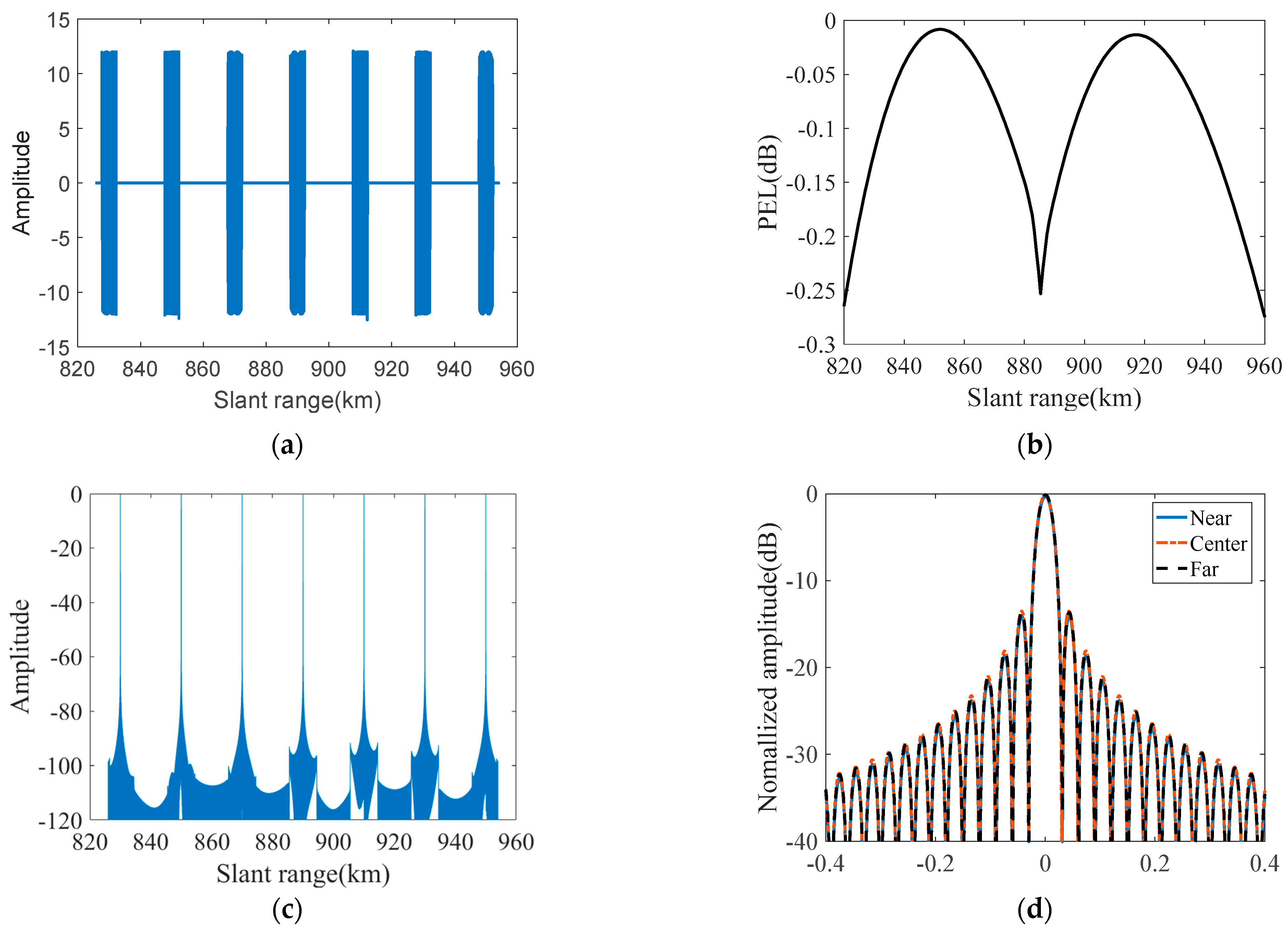
is the direction map with the beam pointing to the center of the pulse. With the simulation parameters listed in Table 1, the simulation results processed by the conventional DBF processor are shown in Figure 3. The signal amplitude modulation could clearly be observed in Figure 3a, as the additional time delays for PEL compensation are not accurately carried out, especially for targets at both edges of the swath. As shown in Figure 3c, if the reference time delay in (10) is selected as the time delay of the imaged swath center, the PEL in the near location in the swath is clearly higher than in the far. To minimize the PEL, the reference time t ref needs to be optimized. It can be seen that the signal amplitude modulation becomes small in Figure 3b, and the worst PEL is reduced from −4.4 dB to −3.5 dB, as shown in Figure 3d.
The linear approximation of θ ( t ) for the arbitrary target P in the whole imaged swath can be expressed as:
θ ( t ) θ ( t p ) + θ ( t ) t | t = t p ( t t p )
In addition to the target position, the range frequency should also be considered, since the pulse bandwidth is relatively large in HRWS SAR. Therefore, for the arbitrary range frequency f p , the expected time delay of the n-th channel for the arbitrary target P can be expressed as:
D n ( f p , t p ) = ( n 1 ) d sin [ θ ( t p ) β ] c ( n 1 ) d f p k r c θ ( t ) t | t = t p
According to the operated time delay in (10) and the desired delay in (14), the time delay deviation can be expressed as:
Δ D n ( f p , t p ) = ( n 1 ) d c { sin [ θ ( t p ) β ] sin [ θ ( t ref ) β ] } ( n 1 ) d k r c [ f p θ ( t ) t | t = t p f c θ ( t ) t | t = t ref ] ( n 1 ) d c [ θ ( t p ) θ ( t ref ) ] ( n 1 ) d f c k r c ( θ ( t ) t | t = t p θ ( t ) t | t = t ref ) ( n 1 ) d k r c ( f p f c ) θ ( t ) t | t = t p
According to (15), the time delay deviation is mainly affected by two parts. The first part of (15) is mainly determined by t ref , and the point target P is closer to the selected reference slant range, the deviation Δ D n would become smaller. The second one is determined by the range frequency, and the large pulse bandwidth will cause the large time delay deviation Δ D n . Furthermore, in the discrete-time domain, the range offset relative to the geometric resolution is more important than the absolute time delay deviation Δ D n . For a fixed time delay deviation, the range offset compensation could be ignored in DBF SAR with a narrow bandwidth, while the range offset must be considered and compensated in SAR with a large bandwidth. Therefore, according to (15), there are two ways to reduce the residual PEL. One is to provide more reference time delays for accurate time delay compensation, and the other is to divide the large pulse bandwidth into multiple sub-pulses.

3. Theories of Two Improved DBF Processors

According to the analysis in Section 2, there are two effective methods to relieve the influence of the PEL. One method is to select different reference times for targets with different range positions in the whole wide swath to provide more accurate time delay compensation, which is implemented by multi-group time delays. The other is to divide the large duration pulse into multiple sub-pulses by BPFs, and all sub-pulses are with a smaller pulse bandwidth. Both the more accurate time delay compensation and the smaller bandwidth are related to the smaller and negligible range offset, which results in a clearly reduced PEL. Therefore, two improved DBF processors are presented in this study, and their corresponding disadvantages are analyzed in this section.

3.1. Improved DBF Processor with Multi-Group Time Delays

In the conventional onboard DBF processor, with the obtained time delay in (8), the single-group time delay could easily be designed after phase shift compensation, as shown in Figure 2. However, the accuracy of the time delay in (8) is not always enough in the whole imaged wide swath, especially for targets at both edges of the wide imaged swath, which results in the unaccepted residual PEL. To obtain more accurate time delays, different reference times are selected for targets with different positions to reduce the PEL. Therefore, the approximation of the time-varying looking angle in (8) is rewritten as follows:
θ ( t ) θ ( t ref ,   k ) + θ ( t ) t | t = t ref ,   k ( t t ref ,   k )
where t ref ,   k ( k = 1 , , K ) is the k-th selected reference time, and K is the number of the reference time delay groups. Afterward, its corresponding time delay for the n-th channel in elevation is obtained as:
D k , n ( t ) = ( n 1 ) d sin [ θ ( t ref , k ) β ] c ( n 1 ) d k r λ θ ( t ) t | t = t ref , k
Compared with the conventional DBF processor, the single-group time delays are replaced by multi-group time delays according to (17). Afterward, echoes of targets with different range locations could be more accurately compensated with different time delays to avoid the unaccepted residual PEL. Figure 4 shows the processing diagram of the proposed improved DBF processor with multi-group time delays, while the number of time delay groups and elevation channels are K and N, respectively.
After the time-varying phase compensation, the multi-group time delays attempt to mitigate the PEL and form multiple groups of echoes. Consequently, echoes of targets with different locations from elevation channels could be well compensated by one of the groups. To reduce the downlink data volume to the ground, multi-group data fusion is carried out to form a single group of raw data.
With the reference time optimization, processing results handled by the improved DBF processor with two-group and four-group time delays are shown and compared in Figure 5. In order to decrease the residual PEL, a more accurate delay is required. Therefore, the number of delay groups should be increased. It can be seen that the signal amplitude modulation is smaller than the processing result handled by the conventional DBF processor in Figure 3, and the residual PEL is controlled within about −1.5 dB and −0.3 dB in the DBF processors with two-group and four-group time delays, respectively. With the increase in the number of time delay groups, the time delay deviations between different channels in elevation are well compensated, and the PEL is clearly decreased.
The DBF processor with multi-group time delays can make the signals of each channel have good coherence before merging and reduce the PEL. However, the output data volume of the DBF processor with multi-group time delays is more than that of the conventional DBF processor, since the additional K − 1 pulse data are recorded and downlinked for the coherent fusion of the multi-group data.

3.2. Improved DBF Processor with Multi-Frequency Time Delays

In the conventional onboard DBF processor, Equation (5) is used to form a time-varying, high-gain. narrow-scanning receiving beam. In fact, it is difficult to accurately control the scanning direction of the receive beam for all range frequencies by Equation (5) under the condition of the large transmitted pulse bandwidth, which will cause range offset deviation. In addition, to decrease the time delay deviation in (15), the transmitted pulse with a large bandwidth could be divided into multiple sub-pulses with a small bandwidth to reduce the range offset, and the transmitted pulse is generally considered to be uniformly divided. As different sub-pulses are with different carrier frequencies, multi-frequency phase shift should be adopted to control the receive beam steering. To reduce the computational complexity of the improved DBF processor, large-bandwidth pulse division via BPF is carried out after phase shifting and multi-channel signal summation. Therefore, the flowchart of the improved DBF processor with multi-frequency time delays is shown in Figure 6, and the number of divided sub-pulses is M.
As shown in Figure 6, the new phase shift in the n-th sub-aperture for the m-th sub-pulse to form a time-varying high-gain sharp receive beam can be expressed as:
w m , n ( t ) = exp { j 2 π ( n 1 ) d sin [ θ m ( t ) β ] f m / c }
where m = 1 , 2 , , M is the serial number of sub-pulses, M is an odd number, θ m ( t ) is the look angle for the m-th sub-pulse, B r is the bandwidth of the transmitted signal, and f m indicates the carrier frequency of the m-th sub-pulse. Since each sub-pulse is with a very small pulse bandwidth, the time delay in Figure 2 for compensation can be ignored. As echoes of the whole imaged swath are mixed at receivers, it is difficult to implement pulse division in the time domain, and the transmitted pulse division only could be implemented by BPFs in the range frequency domain. To reduce the computational complexity, the BPFs for pulse division are designed after multi-frequency phase shifting and multi-channel signal combination in the time domain. It should be noted that the frequency of the band-pass filter must correspond to the phase shifting. Finally, with the multi-band synthesis processing, the processing result of the whole imaged swath by the improved DBF processor with multi-frequency time delays is obtained.
Figure 7 shows the simulation results of the improved DBF processor with multi-frequency time delays, and the transmitted pulse is divided into three and seven sub-pulses in Figure 7a,b, respectively. As no time delay compensation in this improved DBF processor, the signal amplitude modulation could clearly be observed, especially for the three-sub-pulses case. As shown in Figure 7c,d, the residual PEL in the cases of three and even sub-pulses is about −2.6 dB and −0.75 dB, respectively. Furthermore, the residual PEL in the near slant range is clearly higher than the one in the far slant range, since the same range distance in the near slant range corresponds to a larger angular interval, which may lead to more serious amplitude modulation, as shown in Figure 7a.
Table 2 shows the residual PEL of the conventional DBF, the DBF processor with multi-group time delays, and the DBF processor with multi-frequency time delays. It can be seen that two improved DBF processors can relieve the influence of PEL, and it will be better with the increase in the number of delay groups and frequency.

3.3. Major Drawbacks of Two Improved DBF Processors

The improved DBF processor with multi-group time delays can provide more accurate time delay compensation to reduce the PEL by the multi-group time delays. According to the target range position, different reference time delays are selected to obtain the acceptable range offset. The key point of this improved DBF processor is the wide swath divided into multiple narrow sub-swaths, and each sub-swath only needs single-group time delays to obtain the acceptable PEL. To avoid the raw data conflict in the range pulse compression, additional raw data related to the transmitted pulse duration should be recorded and downlinked, which is increased with the number of time delay groups and the transmitted pulse duration. However, the size of the downlinked raw data should be reduced as possible due to the limited onboard data downlink capability in spaceborne SAR. Figure 8 shows the relationship between the pulse duration and the increased data ratio under a different number of time delay groups.
The improved DBF processor with multi-frequency time delays reduces the PEL by decreasing the range offset, which is implemented by the large pulse division, since the small bandwidth corresponds to the small range offset for the same time delay deviation. The channel imbalance including amplitude and phase would be introduced during frequency bandwidth division and synthesis processing, which will reduce the pulse compression performances, as shown in Figure 9. In Figure 9, the simulated amplitude and phase errors are 0.5 dB and 10°. Furthermore, with the increase in divided frequency sub-bands, the amplitude and phase imbalance estimation and compensation will become more difficult.

4. Methodology of Proposed DBF Processor with Multi-Frequency and Multi-Group Time Delays

According to the above analysis in 
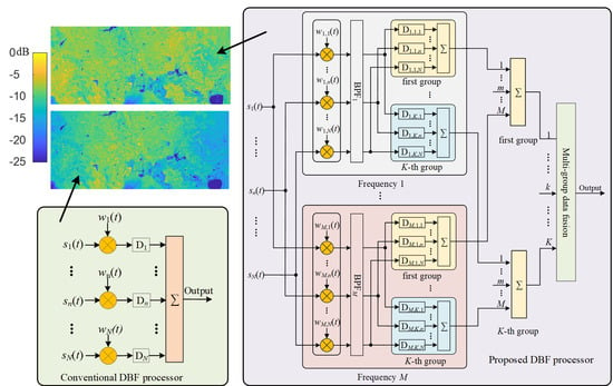
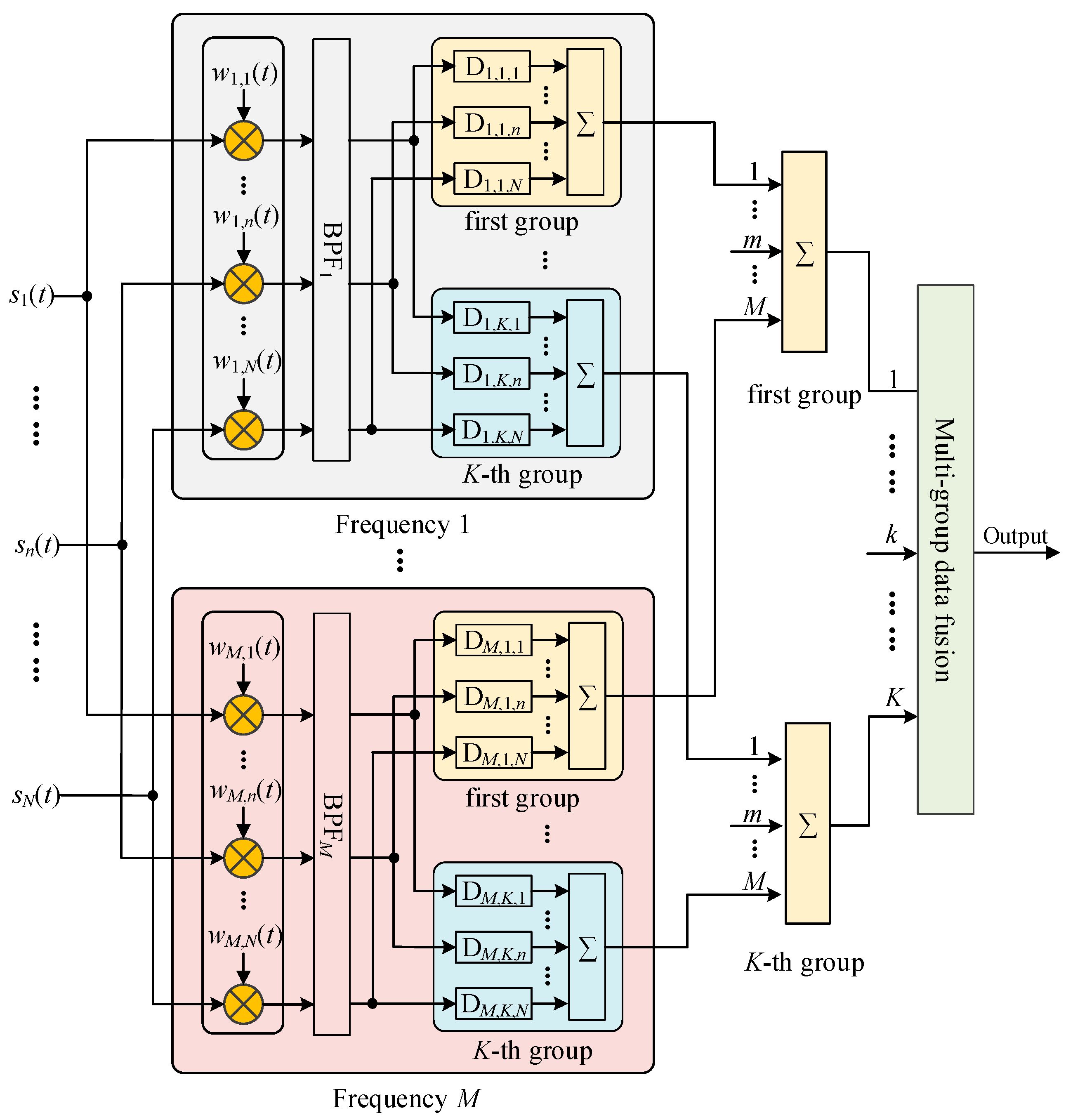
Section 3, both improved DBF methods could reduce the PEL but with unwanted drawbacks. To make full use of the advantages of the two improved DBF methods, a novel DBF processor with multi-frequency and multi-group time delays is proposed in this paper, and its flowchart is shown in Figure 10. In Figure 10, the number of channels, groups of time delay, and sub-bands are N, K, and M, respectively. First, the multi-frequency phase-weighting vectors are multiplied to form sharp receive beams corresponding to different carrier frequencies before the transmitted pulse division. After the transmitted pulse division by BPFs, the multi-group time delays are introduced for compensation to improve DBF performances for each sub-pulse. After multi-channel raw data combination and sub-bands synthesis, the resulting raw data with different reference time delays compensation should be fused into single-channel data to reduce the recorded and downlinked raw data, as shown in Figure 10.
In order to reduce range offsets between different channels in elevation in DBF SAR, the transmitted pulse with the long pulse duration and large bandwidth should be divided into several sub-pulses, and these sub-pulses are with different carrier frequencies and transmitted time delays. However, the transmitted pulse division is implemented in the frequency domain. The multi-channel raw data in elevation are multiplied by multi-frequency phase weighting vectors in the time domain to simultaneously form several sharp beams to the received echoes corresponding to different sub-pulses. The multiplied phase weighting of the n-th sub-aperture corresponding to the m-th sub-pulse can be expressed as:
w m , n ( t ) = exp { j 2 π ( n 1 ) d sin [ θ m ( t ) β ] ( f c + Δ f m ) / c }
with
θ m ( t ) = arccos { ( H + R e ) 2 R e 2 + R m 2 ( t ) 2 ( H + R e ) R m ( t ) }
R m ( t ) = c t 2 + [ m ( M + 1 ) / 2 ] c τ 2
Δ f m = [ m ( M + 1 ) / 2 ] B r M
After phase weighting, echo signals corresponding to the m-th sub-pulse received by the n-th sub-aperture can be expressed as:
s m , n ( t ) = s 1 ( t Δ t n ) exp { j 2 π f c ( n 1 ) d c [ θ m ( t ) θ ( t p ) ] } exp { j 2 π Δ f m ( n 1 ) d c [ θ m ( t ) β ] }
Consequently, the transmitted pulse division is operated in the frequency domain by BPFs. Different from the improved DBF processor in Figure 6, it is suggested to reduce the number of BPFs, since the amplitude and phase imbalance between different frequency sub-bands could be more easily estimated and corrected with fewer sub-bands. Another difference between the proposed DBF processor and the improved DPF processor in Figure 6 is the time delay compensation for all sub-pulses, and it is implemented by multi-group time delays. The approximation of the time-varying looking angle of the m-th sub-pulse can be expressed as follows:
θ m ( t ) θ m ( t k ) + θ m ( t ) t | t = t k ( t t k )
where t k is the k-th selected reference time for the approximation of the time-varying looking angle of the m-th sub-pulse. Afterward, the spectrum signal of the m-th narrow sub-swaths received by the n-th channel in elevation can be expressed as:
S m , n ( f ) exp [ j 2 π f c t p ] rect [ f k r T + ( n 1 ) d ( f c + Δ f m ) c k r T θ m ( t ) t | t = t k ]   exp [ j π f 2 k r ] exp [ j 2 π f ( n 1 ) d c sin ( θ p β ) ] exp [ j 2 π f t p ]   exp [ j 2 π f ( n 1 ) d ( f c + Δ f m ) k r c θ m ( t ) t | t = t k ]
Therefore, with the phase weighting by the m-th phase shift, the k-th-group time delay for the n-th channel in elevation can be expressed as:
D m , k , n = ( n 1 ) d sin [ θ m ( t k ) β ] c ( n 1 ) d ( f c + Δ f m ) k r c θ m ( t ) t | t = t k
The time delay of K groups is evenly divided according to the time-varying angle. If the echo time of the m-th frequency within the range time of the k-th-group, the k-th-group time delay is adopted in the frequency domain. The number of groups for time delays K is obtained as follows:
K = | Δ D N ( f max , t far ) Δ D N ( f min , t near ) | μ B r Δ x M
where indicates the rounding up operator, t far and t near are the time delay for the farthest and nearest targets in the whole imaged swath, respectively, f max and f min are the maximum and minimum of the transmitted pulse, respectively, B r indicates the pulse bandwidth, and Δ x is the acceptable maximum value of the time delay deviation for the desired PEL. In addition, to reduce the PEL, the reference time delay of the m-th-group needs to be optimized. In the reference time optimization, the two-way time delay of the swath center is set to the initial reference time. Afterward, if the time delay deviation Δ D n in the near range is greater than in the far range, the reference time for linear approximation will be selected as the mean value of the original reference time and the two-way time delay of the near range. Otherwise, the reference time delay will be re-selected as the mean value of the original reference time and the two-way time delay of the far range. After about five iterations, the reference time is optimized, and the residual PEL is minimized.
The time delay can be realized by two methods, one is to use finite impulse response (FIR) filters to realize the pipeline processing in the time domain, and the other method is to realize the time delay processing by phase shift compensation in the frequency domain. Considering that the multiple sub-pulse signals need to be obtained in the frequency domain by BPFs, the phase shift compensation in the frequency domain is used to realize the time delay in this paper. Therefore, the k-th phase shift of the compensated time delay for the m-th narrow sub-swaths received by the n-th channel can be expressed as:
H m , k , n ( f ) = exp { j 2 π f ( n 1 ) d sin [ θ m ( t k ) β ] c } + exp [ j 2 π f ( n 1 ) d ( f c + Δ f m ) k r c θ m ( t ) t | t = t k ]
After the time delay compensation, echoes from all elevation channels with the same sub-band and time delay group are combined. Afterward, echoes with different sub-bands are synthesized to form echoes with the whole transmitted bandwidth. Finally, echoes compensated by different time delay groups are fused to reduce the amount of raw data. It is suggested that the number of divided sub-bands should be small and preferably two, since the imbalance between different frequency sub-bands is more easily estimated and corrected in this case.

5. Results

In this section, simulation experiments on both point and distributed targets are carried out to demonstrate the proposed DBF processor with multi-frequency and multi-group time delays, and simulation parameters are listed in Table 1.

5.1. Simulation Experiments on Point Targets

With the same designed scene in Figure 3, Figure 5 and Figure 7, there are seven point targets in the designed swath, and all point targets are equally spaced in the slant range. The spacing between adjacent point targets is 20 km, and the middle point target is with the slant range of 890 km. To reduce the size of the recorded raw data and avoid complex channel imbalance estimation and correction, the number of both the frequency sub-bands and time delay groups are two. Processing results handled by the proposed DBF processor with dual-frequency and two-group time delays are shown in Figure 11. The amplitude modulation of the output signal in the time domain becomes very small, as shown in Figure 11a, and the residual PEL is controlled within about −0.3 dB, as shown in Figure 11b. The max value of the PEL is not zero, since different range frequencies are related to different optimized reference times. Furthermore, seven point targets could be well compressed by the matched filter after the proposed DBF processor, as shown in Figure 11c, while interpolations of compression results of the nearest, middle, and farthest targets are shown in Figure 11d, which show the good pulse compression behavior. The peak powers of simulated point targets from left to right are Figure 11c is −0.2713 dB, −0.1112 dB, −0.0322 dB, −0.0767 dB, −0.0012 dB, and −0.1253 dB.

5.2. Simulation Experiments on Distributed Targets

To further validate the proposed DBF processor and demonstrate its advantages, a simulation experiment on a designed distributed scene is carried out. A focused SAR image, as shown in Figure 12a, is selected for DBF SAR echo simulation, and its original image size is 3 K × 10 K pixels. To simulate echoes of the whole imaged swath, two-dimensional (2D) interpolation of the focused image is applied, and the size of the interpolated image is 9 K × 1400 K pixels. According to the parameters listed in Table 1, the multi-channel raw data of the designed distributed scene in spaceborne DBF SAR are obtained. The raw data combination by the conventional DBF processor is shown in Figure 2, and Figure 12b shows the imaging result of the resulting combined raw data focused by the classical chirp-scaling (CS) algorithm. Figure 12b shows the focusing result of the output raw data of the proposed DBF processor with multi-frequency and multi-group time delays, and the number of both the frequency sub-bands and time delay groups is two. To demonstrate the residual PEL, the normalized image amplitudes shown in Figure 12b,c, which are averaged in azimuth, are compared and plotted in Figure 12d. The residual PEL in Figure 12b is about −4 dB, while the residual PEL in Figure 12c is less than −2 dB, which means that more than a 2 dB improvement is obtained by the improved DBF processor with multi-frequency and multi-group time delays. The PEL values in Figure 12d seem to be clearly higher than the PEL curves in Figure 3 and Figure 11, and the reason for this phenomenon is mainly caused by strong scatterers in the distributed scene, as shown in Figure 12a.

6. Discussion

The proposed DBF processor with multi-frequency and multi-group time delays can relieve the influence of the PEL and improve the SAR system’s receive power. The proposed DBF processor increases downlinked raw data and the difficulty of amplitude and phase imbalance estimation and compensation.
Generally, the DBF processor with dual-frequency and multi-group time delays is suggested to be selected. If the amount of downlinked raw data is too large, the number of time delay groups can be appropriately reduced, and the number of sub-bands can be increased. According to the simulation results in Figure 11, the PEL in the proposed DBF processor with dual-frequency and two-group time delays is within −0.3 dB and acceptable for almost all spaceborne SAR systems.

7. Conclusions

DBF with multiple sub-apertures uniformly distributed in elevation can be widely adopted in future spaceborne SAR missions to achieve the HRWS imaging capacity. However, with the improvement of geometric resolution and swath width, the residual PEL in the conventional DBF processor becomes significant and cannot be neglected. In order to reduce downlinked raw data and avoid amplitude and phase imbalance estimation and compensation an onboard DBF processor with multi-frequency and multi-group time delays is proposed in this paper to reduce the residual PEL. The proposed DBF processor with double-frequency and two-group time delays is simulated on both point and distributed targets. According to the simulation results, the residual PEL is reduced to about 0.3 dB in the HRWS SAR system with a swath slant range of 120 km and a large bandwidth of 1.2 GHz. The tiny PEL in the proposed DBF processor is acceptable for almost all spaceborne SAR systems.

Author Contributions

Conceptualization, W.X.; methodology, W.X.; software, W.X. and Q.Y.; validation, W.X. and C.F.; formal analysis, Q.Y. and P.H.; investigation, W.X. and Q.Y.; resources, W.T.; data curation, Q.Y.; writing—original draft preparation, W.X. and Q.Y.; writing—review and editing, W.X. and P.H.; visualization, P.H.; supervision, W.T and Y.Q.; project administration, P.H. and W.T.; funding acquisition, W.X. and C.F. All authors have read and agreed to the published version of the manuscript.

Funding

This research was funded by National Natural Science Foundation of China under Grant Numbers 62071258, 61971246, and 61631011, in part by the Natural Science Foundation of Inner Mongolia under Grant Numbers 2020ZD18 and 2019MS04004, and in part by the National Defense Key Laboratory Fund Project under Grant Number 6142216190209.

Institutional Review Board Statement

Not applicable.

Informed Consent Statement

No applicable.

Data Availability Statement

No applicable.

Conflicts of Interest

The authors declare no conflict of interest.

References

  1. Jiang, K.; Wang, C.; Zhang, H.; Chen, W.; Zhang, B.; Tang, Y.; Wu, F. Damage analysis of 2008 Wenchuan earthquake using SAR images. In Proceedings of the 2009 IEEE International Geoscience and Remote Sensing Symposium, Cape Town, South Africa, 12–17 July 2009; pp. V-108–V-111. [Google Scholar]
  2. Shimada, M. New earth observation scenario using the ALOS-2 with the L-band high-resolution and full-polarimetric SAR. In Proceedings of the Conference Proceedings of 2013 Asia-Pacific Conference on Synthetic Aperture Radar (APSAR), Tsukuba, Japan, 23–27 September 2013; p. 1. [Google Scholar]
  3. Moreira, A.; Krieger, G.; Hajnsek, I.; Papathanassiou, K.; Younis, M.; Lopez-Dekker, P.; Huber, S.; Villano, M.; Pardini, M.; Eineder, M.; et al. Tandem-L: A Highly Innovative Bistatic SAR Mission for Global Observation of Dynamic Processes on the Earth’s Surface. IEEE Geosci. Remote Sens. Mag. 2015, 3, 8–23. [Google Scholar] [CrossRef]
  4. Kader, W.B.P.v. SAR earth observation satellites heritage, status quo and way ahead in Europe and Germany. In Proceedings of the 2016 21st International Conference on Microwave, Radar and Wireless Communications (MIKON), Krakow, Poland, 9–11 May 2016; pp. 1–4. [Google Scholar]
  5. Huber, S.; Almeida, F.Q.d.; Villano, M.; Younis, M.; Krieger, G.; Moreira, A. Tandem-L: A Technical Perspective on Future Spaceborne SAR Sensors for Earth Observation. IEEE Trans. Geosci. Remote Sens. 2018, 56, 4792–4807. [Google Scholar] [CrossRef] [Green Version]
  6. Freeman, A.; Johnson, W.T.K.; Huneycutt, B.; Jordan, R.; Hensley, S.; Siqueira, P.; Curlander, J. The “Myth” of the minimum SAR antenna area constraint. IEEE Trans. Geosci. Remote Sens. 2000, 38, 320–324. [Google Scholar] [CrossRef] [Green Version]
  7. Gebert, N.; Fois, F.; Helière, F.; Lin, C.; Arcioni, M. Multi-channel SAR: Relaxing the minimum antenna area constraint. In Proceedings of the 2011 12th International Radar Symposium (IRS), Leipzig, Germany, 7–9 September 2011; pp. 53–58. [Google Scholar]
  8. Zhao, S.; Wang, R.; Deng, Y.; Zhang, Z.; Li, N.; Guo, L.; Wang, W. Modifications on Multichannel Reconstruction Algorithm for SAR Processing Based on Periodic Nonuniform Sampling Theory and Nonuniform Fast Fourier Transform. IEEE J. Sel. Top. Appl. Earth Obs. Remote Sens. 2015, 8, 4998–5006. [Google Scholar] [CrossRef]
  9. Krieger, G.; Gebert, N.; Moreira, A. Unambiguous SAR signal reconstruction from nonuniform displaced phase center sampling. IEEE Geosci. Remote Sens. Lett. 2004, 1, 260–264. [Google Scholar] [CrossRef] [Green Version]
  10. Zhenfang, L.; Hongyang, W.; Tao, S.; Zheng, B. Generation of wide-swath and high-resolution SAR images from multichannel small spaceborne SAR systems. IEEE Geosci. Remote Sens. Lett. 2005, 2, 82–86. [Google Scholar] [CrossRef]
  11. Krieger, G.; Gebert, N.; Moreira, A. Multidimensional Waveform Encoding: A New Digital Beamforming Technique for Synthetic Aperture Radar Remote Sensing. IEEE Trans. Geosci. Remote Sens. 2008, 46, 31–46. [Google Scholar] [CrossRef] [Green Version]
  12. Gebert, N.; Krieger, G.; Moreira, A. Digital Beamforming for HRWS-SAR Imaging: System Design, Performance and Optimization Strategies. In Proceedings of the 2006 IEEE International Symposium on Geoscience and Remote Sensing, Denver, CO, USA, 31 July–4 August 2006; pp. 1836–1839. [Google Scholar]
  13. Bollian, T.; Osmanoglu, B.; Rincon, R.; Lee, S.-K.; Fatoyinbo, T. Adaptive Antenna Pattern Notching of Interference in Synthetic Aperture Radar Data Using Digital Beamforming. Remote Sens. 2019, 11, 1346. [Google Scholar] [CrossRef] [Green Version]
  14. Huang, P.; Xu, W. ASTC-MIMO-TOPS Mode with Digital Beam-Forming in Elevation for High-Resolution Wide-Swath Imaging. Remote Sens. 2015, 7, 2952. [Google Scholar] [CrossRef] [Green Version]
  15. Gebert, N.; Villano, M.; Krieger, G.; Moreira, A. Errata: Digital Beamforming on Receive: Techniques and Optimization Strategies for High-Resolution Wide-Swath SAR Imaging. IEEE Trans. Aerosp. Electron. Syst. 2013, 49, 2110. [Google Scholar] [CrossRef] [Green Version]
  16. Wang, W.; Wang, R.; Deng, Y.; Balz, T.; Hong, F.; Xu, W. An Improved Processing Scheme of Digital Beam-Forming in Elevation for Reducing Resource Occupation. IEEE Geosci. Remote Sens. Lett. 2016, 13, 309–313. [Google Scholar] [CrossRef]
  17. Reigber, A.; Schreiber, E.; Trappschuh, K.; Pasch, S.; Müller, G.; Kirchner, D.; Geßwein, D.; Schewe, S.; Nottensteiner, A.; Limbach, M.; et al. The High-Resolution Digital-Beamforming Airborne SAR System DBFSAR. Remote Sens. 2020, 12, 1710. [Google Scholar] [CrossRef]
  18. Wang, W.; Wang, R.; Deng, Y.; Xu, W.; Hou, L. Improved digital beam-forming approach with scaling function for range multi-channel synthetic aperture radar system. IET Radar Sonar Navig. 2016, 10, 379–385. [Google Scholar] [CrossRef]
  19. Zhao, Q.; Zhang, Y.; Wang, W.; Liu, K.; Deng, Y.; Zhang, H.; Wang, Y.; Zhou, Y.; Wang, R. On the Frequency Dispersion in DBF SAR and Digital Scalloped Beamforming. IEEE Trans. Geosci. Remote Sens. 2020, 58, 3619–3632. [Google Scholar] [CrossRef]
  20. Zhao, Q.; Zhang, Y.; Wang, R.; Deng, Y.; Wang, W.; Zhang, H.; Wang, X. Estimation and Removal of Strong Range Ambiguities in Multistatic Synthetic Aperture Radar With Multiple Elevation Beams. IEEE Geosci. Remote Sens. Lett. 2019, 16, 407–411. [Google Scholar] [CrossRef]
  21. Wang, S.; Sun, Y.; He, F.; Sun, Z.; Li, P.; Dong, Z. DBF Processing in Range-Doppler Domain for MWE SAR Waveform Separation Based on Digital Array-Fed Reflector Antenna. Remote Sens. 2020, 12, 3161. [Google Scholar] [CrossRef]
  22. Zhao, Q.; Zhang, Y.; Wang, W.; Deng, Y.; Yu, W.; Zhou, Y.; Wang, R. Echo Separation for Space-Time Waveform-Encoding SAR With Digital Scalloped Beamforming and Adaptive Multiple Null-Steering. IEEE Geosci. Remote Sens. Lett. 2021, 18, 92–96. [Google Scholar] [CrossRef]
  23. Younis, M.; Rommel, T.; Bordoni, F.; Krieger, G.; Moreira, A. On the Pulse Extension Loss in Digital Beamforming SAR. IEEE Geosci. Remote Sens. Lett. 2015, 12, 1436–1440. [Google Scholar] [CrossRef]
  24. Younis, M.; Huber, S.; Patyuchenko, A.; Bordoni, F.; Krieger, G. Performance Comparison of Reflector- and Planar-Antenna Based Digital Beam-Forming SAR. Int. J. Antennas Propag. 2009, 2009, 614931. [Google Scholar] [CrossRef]
  25. Fan, F.; Hongxing, D.; Xiaomin, T.; Guangting, L.; Caipin, L. An improved scheme of Digital Beam-Forming in elevation for spaceborne SAR. In Proceedings of the IET International Radar Conference 2013, Xi’an, China, 14–16 April 2013; pp. 1–6. [Google Scholar]
  26. Suess, M.; Wiesbeck, W. Side-Looking Synthetic Aperture Radar System. Euro Patent 1 241 487 A1, 15 March 2001. [Google Scholar]
Figure 1. Imaging geometry of DBF SAR with multiple sub-apertures in elevation.
Remotesensing 13 04354 g001
Figure 2. Flowchart of the conventional DBF processor with phase and time delay compensation.
Remotesensing 13 04354 g002
Figure 3. Simulation results processed by the conventional DBF processor. (a) Real part of echoes with the selected reference slant range of 890 km. (b) Real part of echoes with the optimized reference range of 875 km. (c) Residual PEL in (a,d). Residual PEL in (a,b).
Remotesensing 13 04354 g003aRemotesensing 13 04354 g003b
Figure 4. Processing diagram of the improved DBF processor with multi-group time delays.
Remotesensing 13 04354 g004
Figure 5. Simulation results processed by the DBF processor with the multi-group time delays. (a) Real part of echoes handled by the improved DBF processor with two-group time delays. (b) Real part of echoes handled by the improved DBF processor with four-group time delays. (c) Residual PEL in (a,d). Residual PEL in (a,b).
Remotesensing 13 04354 g005
Figure 6. Processing diagram of the improved DBF processor with multi-frequency time delays.
Remotesensing 13 04354 g006
Figure 7. Processing results of signals processed by the improved DBF processor with multi-frequency time delays. (a) Real part of echoes with 3 sub-pulses. (b) Real part of echoes with 7 sub-pulses. (c) Residual PEL in (a,d). Residual PEL in (a,b).
Remotesensing 13 04354 g007
Figure 8. Relationship between the increased data ratio and the transmitted pulse duration.
Remotesensing 13 04354 g008
Figure 9. Pulse compression results of the improved DBF processor with multi-frequency time delays (a) Pulse compression results with amplitude errors between different frequency sub-bands. (b) Pulse compression results with phase errors between different frequency sub-bands.
Remotesensing 13 04354 g009
Figure 10. Processing diagram of the proposed DBF processor with multi-frequency and multi-group time delays.
Remotesensing 13 04354 g010
Figure 11. Processing results of the proposed DBF processor. (a) Real parts of the output signal handled by the proposed DBF processor. (b) Residual PEL. (c) Range compression result. (d) Interpolations of compression results of the selected three point targets.
Remotesensing 13 04354 g011
Figure 12. Processing results of the simulated distributed scene by the conventional DBF processor and the proposed DBF processor. (a) Focused SAR image for echo simulation. (b) Conventional DBF processor processing result. (c) Proposed DBF processor processing result. (d) Normalized average amplitude comparison.
Remotesensing 13 04354 g012
Table 1. Simulation parameters.
ParametersSymbolValue
Radius of the earth R e 6371 km
Orbit heightH750 km
Look angle of antenna normal direction β 30°
Carrier frequency f c 9.6 GHz
Number of channels in elevationN12
Pulse durationT30 us
Subaperture spacingd0.3 m
Pulse bandwidth B r 1200 MHz
Range sampling frequency f s 1440 MHz
Table 2. PEL of simulated point targets.
MethodTarget 1Target 2Target 3Target 4Target 5Target 6Target 7
Conventional DBF−3.569 dB−1.712 dB−0.405 dB0 −0.319 dB−1.136 dB−2.012 dB
Conventional DBF after optimization−2.562 dB−0.799 dB−0.029 dB−0.023 dB−1.028 dB−2.125 dB−3.128 dB
DBF with two-group time delays−0.431 dB−0.455 dB−0.851 dB−0.392 dB−0.002 dB−0.216 dB−0.806 dB
DBF with four-group time delays−0.005 dB−0.091 dB−0.183 dB−0.002 dB−0.254 dB−0.021 dB−0.115 dB
DBF with 3 sub-bands−1.982 dB−1.152 dB−0.479 dB−0.148 dB−0.009 dB−0.027 dB−0.162 dB
DBF with 7 sub-bands−0.558 dB−0.289 dB−0.127 dB−0.035 dB−0.002 dB−0.007 dB−0.043 dB
Publisher’s Note: MDPI stays neutral with regard to jurisdictional claims in published maps and institutional affiliations.

