Article

Assessing Urban Landslide Dynamics through Multi-Temporal InSAR Techniques and Slope Numerical Modeling

1
Department of Geography, Faculty of Geography and Geology, Alexandru Ioan Cuza University of Iași, 700505 Iași, Romania
2
Independent Researcher, Via S, Dalesmanini 26, Vigonza, 35010 Padova, Italy
3
Department of Geosciences, University of Padova, 35131 Padova, Italy
4
Sarmap SA, Via Stazione 52, 6987 Caslano, Switzerland
*
Author to whom correspondence should be addressed.
Remote Sens. 2021, 13(19), 3862; https://doi.org/10.3390/rs13193862
Submission received: 23 July 2021 / Revised: 21 September 2021 / Accepted: 23 September 2021 / Published: 27 September 2021
(This article belongs to the Special Issue SAR Imagery for Landslide Detection and Prediction)

Abstract

:
Landslides threaten more than before the urbanized areas and are a worldwide growing problem for the already affected communities and the local authorities committed to landslide risk management and mitigation. For this reason, it is essential to analyze landslide dynamics and environmental conditioning factors. Various techniques and instruments exist for landslide investigation and monitoring. Out of these, Multi-temporal Synthetic Aperture Radar Interferometry (MT-InSAR) techniques have been widely used in the last decades. Their capabilities are enhanced by the availability of the active Sentinel-1 mission, whose 6-day revisiting time enables near real-time monitoring of landslides. Interferometric results, coupled with ground measurements or other approaches such as numerical modeling, significantly improve the knowledge of the investigated surface processes. In this work, we processed the C-band SAR images of the available European Space Agency (ESA) satellite missions, using MT-InSAR methods to identify the surface deformations related to landslides affecting the Iași Municipality (Eastern Romania). The results (i.e., velocity maps) point out the most active landslides with velocities of up to 20 mm/year measured along the satellite Line of Sight (LOS). Following, we focused on the most problematic landslide that affects the Țicău neighborhood and is well-known for its significant implications that it had. To better understand its behavior and the sensitivity of the displacements to the environmental factors (i.e., rainfall), we carried out 2D numerical modeling using a finite difference code. The simulated displacement field is consistent with the InSAR displacements and reveals the most active sectors of the landslide and insights about its mechanism.

1. Introduction

The human impact, through topographic and hydrologic modifications, is a triggering and preparatory factor for landslides. At the same time, as landslides evolve, they will control human activities, and a feedback loop will occur. Landslides limit and interfere with the infrastructure development, utility networks or may obstruct the expansion of urbanized areas. In the worst-case scenario, they destroy and inflict damages to buildings, infrastructure, and city heritage [1] and generate substantial economic losses [2,3,4,5,6,7]. Many sensing techniques, tools, and instruments are developing to detect, monitor, and analyze landslide processes. The Multi-temporal Interferometric Synthetic Aperture Radar (MT-InSAR) techniques are one of them, and more and more, they are used to investigate landslide hazards. The reliability and consistency of their results make them a great source of information for supporting decision-making policies for landslide risk and management.
Differential SAR Interferometry (DInSAR) techniques use radio’s microwave properties to estimate the rate of ground displacement with millimeter accuracy. The measurement of relative surface displacement between two SAR acquisitions, calculated as the distance difference between a satellite antenna and ground objects, is recorded as the phase shifting of the backscattered echo [8,9,10]. The exploitation of the signal’s phase property over a specific area results in the generation of an interferogram [8,11]. The interferogram represents a matrix of numerical values corresponding to phase variations, usable for the generation of Digital Elevation Models (DEMs) [12,13,14] or the detection of ground surface changes [10,15,16]. The working principle of DInSAR to quantify the displacements relies on the removal of topographic influence out of the original interferogram by using a DEM. More comprehensively, the backscattered signal is the sum of many contributors whose effects have to be considered and removed to isolate the displacement fringes. Besides the displacement component and topography, the interferometric phase is also subjected to the atmosphere’s influence, the geometric and temporal decorrelations introduced by possible orbital errors, and the phase noise [11,17,18,19,20]. In the last two decades, different sophisticated algorithms that consider more than three SAR acquisitions to calculate and remove such influences were developed. Although they have different strategies to estimate the displacement component, these multi-temporal interferometry techniques [21] such as Permanent Scatterer Interferometry (PSI) [22,23] and Small BAseline Subset (SBAS) [24] can overcome the DInSAR limitations and provide millimeter accuracy measurements over a long period. Hence, their potential to investigate landslides rapidly increased, not only for landslides mapping and monitoring their behavior and dynamics but also for detecting early failure indicators [18,21,25,26,27,28,29,30,31,32,33,34,35,36,37,38,39,40,41,42,43,44,45,46,47].
The use of numerical simulations for landslide investigation aims to appropriately determine the stability conditions of the slope and its potential failure mechanisms [48]. Identifying the factors that destabilize the slope and lead to the triggering of a possible event can be used to assess and mitigate the hazard. Accordingly, effective policies and strategies may be proposed and implemented to stabilize the displaced material [49,50,51]. Numerical modeling of slopes makes use of mathematical equations to solve the mechanical response of the unstable mass. Regardless of the employed technique, i.e., Finite Elements (FE), Discrete Elements (DE), or Finite Difference Method (FDM), these approaches focus on deformation analysis as well as the safety factor of the slope [48].
Many studies integrate MT-InSAR techniques and numerical modeling due to their high effectiveness in monitoring and investigating the state of landslides dynamics [46,52,53,54]. Using both approaches is highly beneficial as they allow us to evaluate and monitor the landslide activity over large areas and, additionally, to perform fast investigations of specific cases where fast-paced evolving surface deformations are detected. The outcome of MT-InSAR techniques consists of deformation velocity maps and displacement time series. Each measurement quantifies, with millimeter accuracy, the change of the distance between sensor and target in the satellite Line Of Sight (LOS). Thus, the MT-InSAR outputs provide information about the surface velocity and the extent of the process. At the same time, the simulations can evaluate multiple failure scenarios to explain the material’s physical behavior of the observed displacements. Their capabilities are proven to work not only in the study of landslides but also in other fields such as dam monitoring [55] and mining activities [56,57]. Even though these two complementary techniques are employed more and more in the study of earth surface deformations, they are primarily used in areas supported by lots of in situ data [53,55,58,59]. In contrast, their use in regions lacking ground measurements is still challenging and not yet fully exploited.
This study firstly uses the MT-InSAR techniques to identify the critical areas within Iași Municipality showing landslide-related deformations. Further on, we focus on the Țicău landslide, one of the active landslides that affect the residential neighborhoods. The challenging part of the investigation is related to the lack of in-situ data required to model the behavior of landslide material. To understand its failure mechanism and dynamics, we set up a two-dimensional Finite Difference section along the slope and run several scenarios which potentially describe the observed deformations and pattern. Lastly, we analyzed the simulations and the MT-InSAR results, the velocity maps, the displacement time series, and the magnitude of displacements to point out the landslide body’s active and most dangerous parts and support the proposed sliding mechanism and the geomorphological landslide type.

2. Study Area

The Municipality of Iași (91.5 km2) is the most important city of the north-eastern part of Romania (Figure 1). This area is constantly facing landslide-related deformations being not only one of the landslide hot-spots of the nation [60], but it is recognized at the European scale as well [61]. In the northern part of the city, the terrain morphology is characterized by gentle hillslopes and cuesta landforms with elevations of 200–220 m asl. In contrast, a hilly morphology defines the southern side with steep escarpments and higher altitudes of up to 404 m asl.
The morphology of the Iași area developed on a monoclinic geological structure [64,65,66] under the migration and incision of Bahlui River and its tributaries towards the south, which generated asymmetric hills and structural valleys [67,68,69]. The present-day morphostructure, particularly the lithology, coupled with the small depths of the phreatic level and springs [70], serves as key-conditioning factors for landslide reactivations. The lithology consists of claystones and mudstones interbedded with sandy layers deposited during the Middle Miocene [65,71,72]. In the southernmost part of the area, where the elevations are higher than 320 m asl, a caprock of calcarenites, oolitic calcarenites, and quartz arenites interbedded by sands and claystones outcrops [65,71,72,73]. Overlaying these deposits is a 40 m thick layer of sand. The above described geological formations are covered on ridges and gentle hillslopes by quaternary deposits consisting of fluvial gravels and clays with varying thicknesses from 2 to 5 m, and loess that measures up to 25 m in some cases [70,74,75].
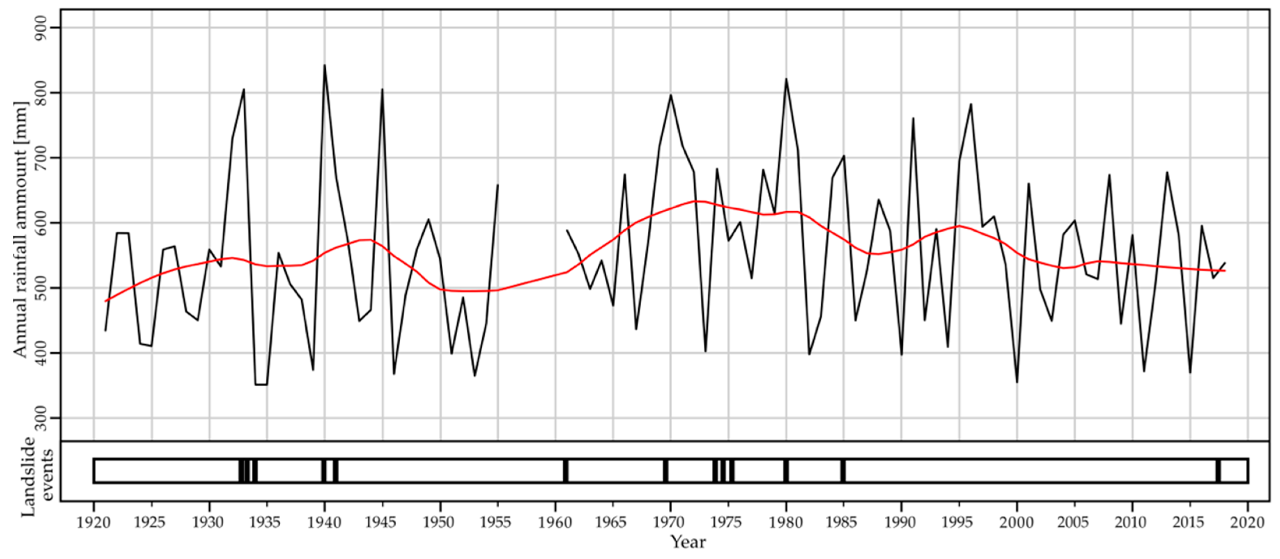
The dry climate is specific for the area and has mean annual rainfall values of 560 mm/year [76]. Rainy periods were recorded (Figure 2) in 1920–1950 and 1960–2000, a situation which might indicate a 30-40 years humid cycle separated by shorter dry periods [77]. These rainy periods caused the increase of the groundwater table, favoring the occurrence of landslides [77,78,79].
The slopes are shaped by landslides [80,81,82] which might reactivate after rainfall events, particularly during the spring season [62,77]. Many cases of landslide reactivations were reported by various authors [62,78,79,83,84] or by local authorities and mass media, as they repeatedly damaged the residential buildings, road network, and utility infrastructure.
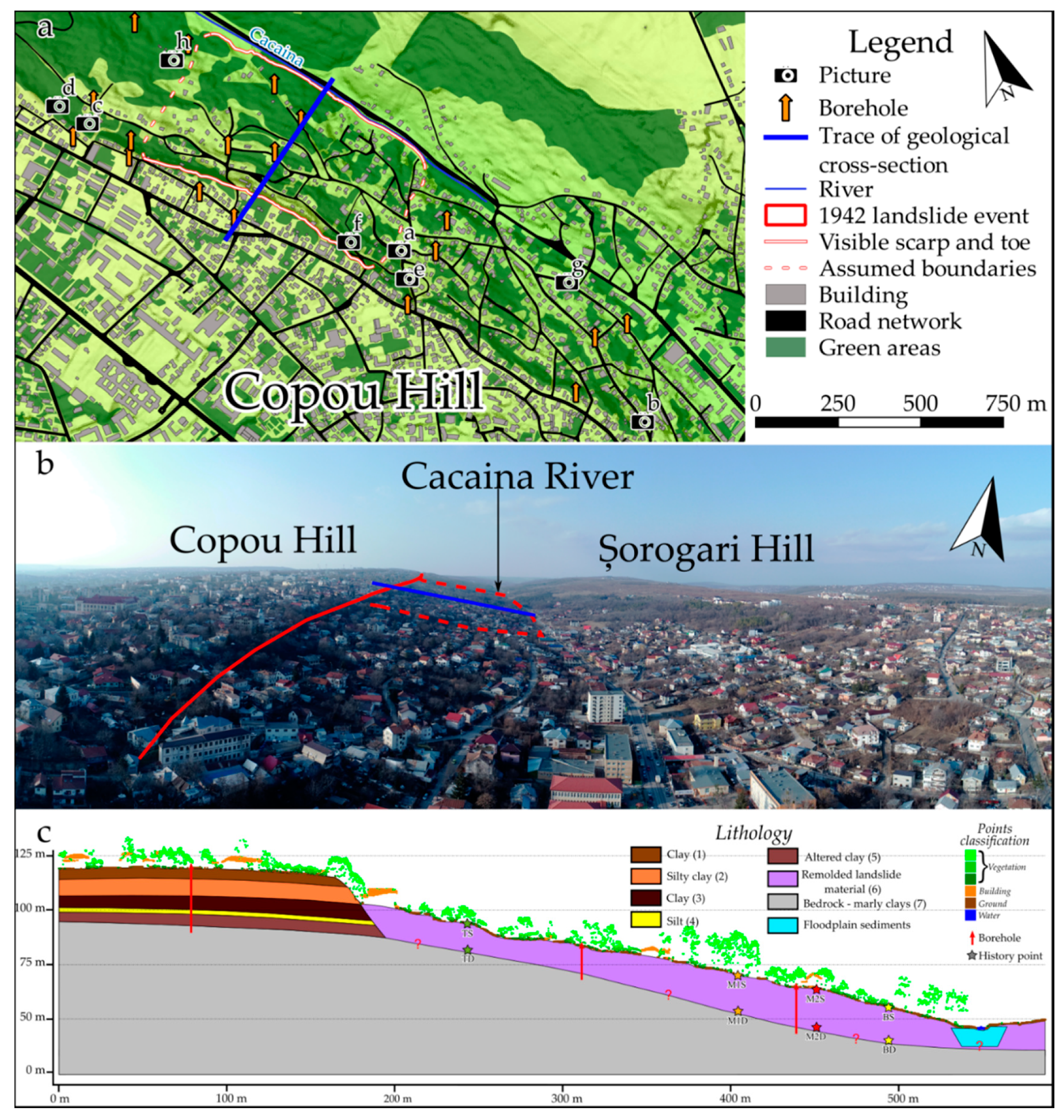
The slope investigated in detail (Figure 3) was affected by a relevant landslide reactivation in the spring of 1942. More than 350 houses were destroyed by the event, along with the road network. The event created the main scarp of 6–7 m in height and about 800 m in length [78]. Downslope, the material reached the Cacaina River floodplain and generated typical morphology with mounds and micro depressions of 1–2 m of height difference, out of which spring waters emerged more than one month after the event. The triggering factor was the prolonged rainfall, which started in the previous autumn, coupled with the snowmelt.
After the event, several remedial works, such as drainage systems and passive mechanic infrastructures, were carried out to drain the area and stabilize the sliding material. However, the passive stabilization infrastructure and drainage systems designed to prevent further displacements do not work anymore, probably due to degradation, and slope deformations are currently active.
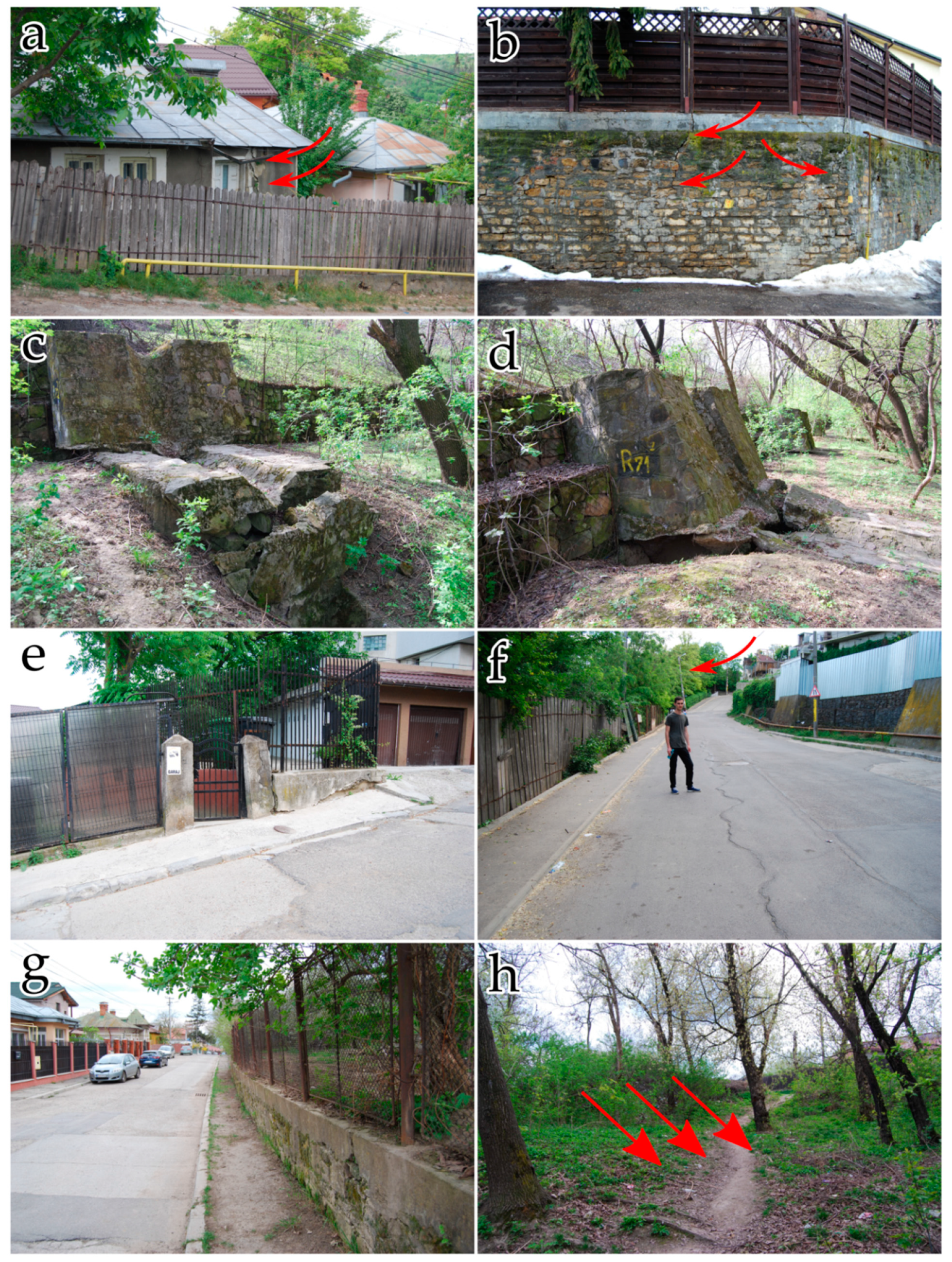
At the moment, the area is characterized by hummocky-like landforms and is affected by very slow-moving slides. Pieces of evidence of surface displacements were identified during in-situ surveys and manifest as wall cracks, wall bulging, cracks in the buildings’ outer walls, damages to passive stabilization infrastructures, tilted trees, leaned electric poles, road cracks, and bumps (Figure 4).

3. Materials and Methods

3.1. SAR Data and MT-InSAR Methods

The landslide deformations that affect the Municipality of Iași were investigated for more than 25 years, from 1992 to 2018, using C-band SAR data acquired by different sensors (Table 1). We processed the available ERS-1, ERS-2, ENVISAT, and Sentinel-1 SAR images provided by the European Space Agency (ESA). Both satellites acquisition geometries, ascending and descending, were used for our analysis to cross-validate our outputs and increase the spatial extent of information retrieval. Additionally, we used a 5 × 5 m high-resolution LiDAR DSM, provided by Prut-Bârlad Water Administration, to remove the topographic phase and geocode the results.
The data stacks were processed using the Interferometry Stacking tool of Sarscape v5.4. This tool includes Permanent Scatterers Interferometry (PSI) [17,22,23] and Small BAseline Subset (SBAS) [24,88] processing techniques. The use of one method or the other depends on the number of SAR images available and the ground conditions [21,89,90,91]. These advanced techniques employ different strategies to provide high accuracy results and have their pros and cons. Their development overcomes the limitations of DInSAR, such as the temporal and spatial decorrelations, the phase unwrapping errors, and the artifacts due to the atmospheric component [18,20,21].
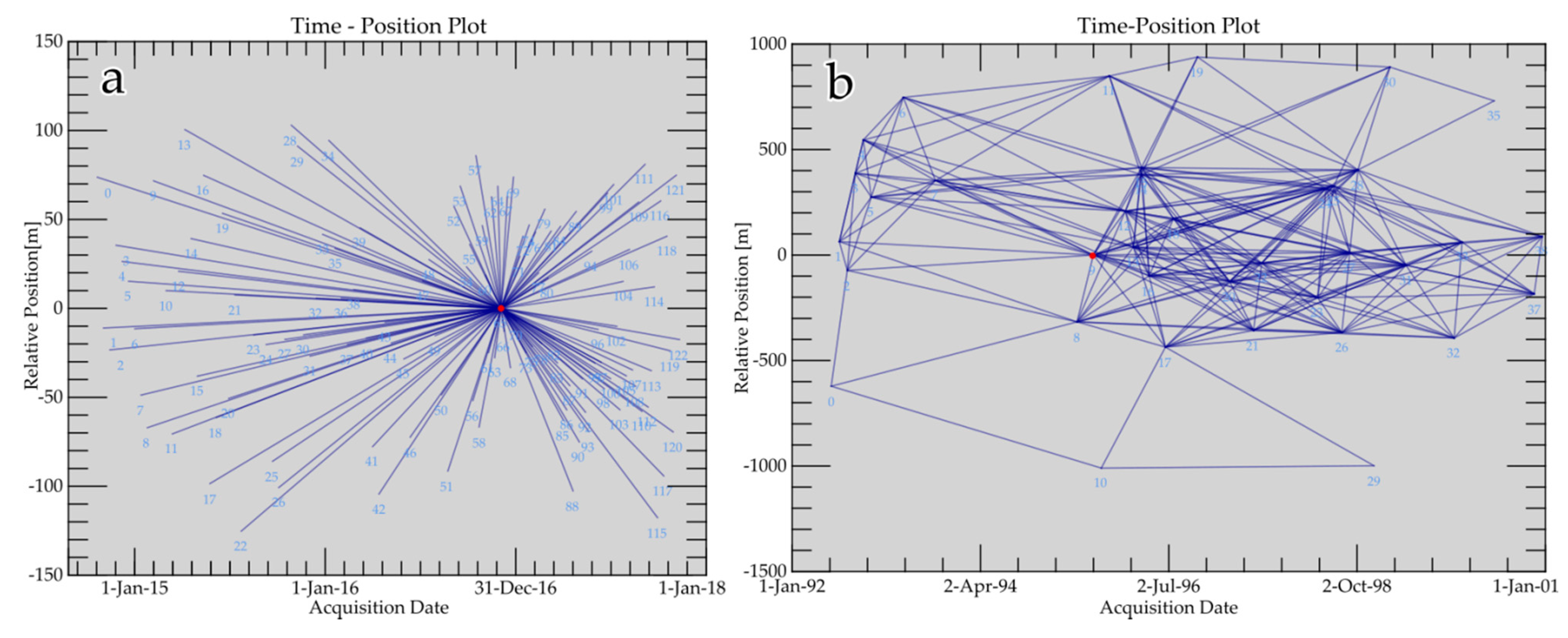
PSI is the first stacking interferometry algorithm developed to overcome some of DInSAR shortcomings [17,22,23]. It considers the entire dataset of SAR acquisitions to create interferograms between a so-called master image and all the other slaves with no restrictions in terms of temporal and spatial baselines (Figure 5a). After the connection graph generation, described in the previous sentence, the PS workflow implemented in Sarscape consists of the following steps: (i) interferometric process, which executes the following sequence automatically: coregistration, interferogram generation, flattening using the high-resolution DSM, and PSs selection by considering the Amplitude Dispersion Index (ADI); (ii) first inversion during which the topographic residuals and the displacement velocity are estimated by using a linear velocity model and removed from the complex interferograms; (iii) the second inversion uses the linear model products calculated previously to estimate the atmospheric components by using a low-pass filter (1000 m) and a high-pass filter (365 days), and fit the final displacement velocity model; (iv) geocoding of the final PS products.
The permanent scatterers (PS) are targets on the ground that are not affected by temporal decorrelation and maintain their signal phase-coherent throughout the analyzed period. Because of this, in Sarscape, the approach is limited to a certain number of sufficiently high coherent targets and requires a large number of images. This characteristic might be a constraint of technique for non-urban areas and areas dominated by vegetation. However, it is reliable in urbanized areas as the buildings maintain a coherent backscattering signal in time. In our case, we considered only the PS measurements with coherence greater than 0.75 and discarded those lower than this threshold. Thus, this approach is suitable for our study case, especially with Sentinel-1A/B datasets characterized by a short repeating cycle between acquisitions.
The SBAS implementation in Sarscape exploits the phase difference of spatially distributed scatterers to measure the ground deformation. Compared to the PSI approach, this technique is feasible to be used with a smaller stack of images as it pairs all the SAR images defined by user-specified temporal and spatial baselines (Figure 5b) to reduce the decorrelations and phase noise. The multilooking of data and the small subsets connection increase the spatial information achievable by analyzing a smaller stack of SAR images. However, as an effect of multilooking, this approach is not suitable to detect local deformation. In our case, we applied the SBAS technique to ERS 1/2 and ENVISAT datasets as the number of available images was limited.
The workflow for the SBAS module in Sarscape is: (i) connection graph generation, explained earlier; (ii) interferometric step, which generates a stack of interferograms, filters them using the Goldstein adaptive filter, and then the phase is unwrapped using the Delaunay Minimum Cost Flow method; (iii) refinement and re-flattening, which estimates and removes the topographic and constant phases as well as the possible phase ramps from the unwrapped stack; (iv) first inversion, the first estimate of the displacement rate and residual heights are calculated and used to re-flatten the interferograms. A second unwrapping is also performed; (v) the second inversion removes the atmospheric phase component to clean and calculate the final displacement velocity and time series; (vi) geocoding of the final products.
Since the LOS displacements are 1D, we used the method of [29] to project the velocity along the slope for the Sentinel-1 PS. To resolve the components of the velocity, we also used [29] approach to compute the E-W and vertical displacements, using the information from both orbits also for Sentinel-1 PS (points in 10-m vicinity were selected).

3.2. Statistical Post-Processing of PS Measurements

To objectively evaluate the areas that show a consistent deformation trend, we used the non-parametric Mann-Kendall test [92] to identify the PS points that show a displacement time series trend (which might be different from a linear trend, respectively monotonic) and the slope of the linear trend which assesses the magnitude of the deformation for automatic filtering purposes. We employed the Man-Kendall test (MK) in Rstat through the mk.test function of the trend package [93]. Each point’s resulting p-value is used to select those that have a significant trend (p-value smaller than 0.0000005). Further filtering is done using the linear regression slope, which should be higher/smaller than 0.15/−0.15 (depending on the satellite’s orbit) to eliminate the points that show a weaker trend. For the selection of the clusters characterized by high deformation rates, the kernel density (density function) of the PS points was estimated using velocity as a covariate (rhohat function) in the spatstat R package [94,95]. This approach can point out areas that show deformation rates over larger spatial extents and remove single or a few deformation points. That might be related to land-use change (in our study, this situation is related to new buildings constructed during the monitoring period) or particular topographic cases (new buildings constructed over disturbed material fillings that do not reflect the hillslope’s state).
To investigate the relationships between displacement and rainfall, we used the breakpoint and trend calculation R package greenbrown [96,97]. In our case, the breakpoints and trends were computed based on the quantile regression to the median, using the Trend function from the greenbrown R package. For the detection of the breakpoints, the approach uses iteratively the ordinary-least squares moving sum (MOSUM) test (if the test indicates a significant structural change at p ≤ 0.05), the number and location of the breakpoints are estimated by minimizing the Bayesian Information Criterion (BIC), and by reducing the residual sum of squares of this regression respectively [96,97,98,99]. The displacement rate trends are correlated with the precipitation of ECA&D data [86,87] for the Iaşi meteorological station to potentially identify the behavior of representative targets over the Țicău landslide after rainfall events.

3.3. Ground-Based Data, Model Setup, and Numerical Modeling

The investigated area faces many shortcomings in terms of geotechnical data and in-situ measurements. Currently, the landslide is not well assessed as there are no instruments installed over the site or monitoring surveys carried on. The available information consists of several exploratory borings drilled in 2006 and published in the Ph.D. thesis of [100]. Their description provides information about the lithological limits, the water table level measured during the drilling, the unit weight of materials, plasticity indices, and intrinsic strength parameters.
The slope stability analysis was done using the 2D Finite Difference code along the section crossing the landslide (Figure 2a). We subdivided the model into seven units of geo-materials (Figure 2c): a succession of five layers in the upper part of the slope, the landslide debris unit in the middle and lower sectors, and the geological bedrock. To these units of geo-materials, we assigned the properties available in the literature.
The model consists of elements, nodes, and zones, to which specific physical and mechanical parameters are attributed and used to compute the internal stresses and strains within the slope. To perform the simulation of the behavior of the slope, the initial state of the model is subjected to various parametric changes related to its geometrical and mechanical characteristics, cyclic stresses, and potential anthropic activities or the increase in rainfall intensity which might lead to landslides triggering. The typically achieved solution concludes when the internal stresses reach the state of equilibrium, and no more strains develop, or when the collapse occurs.
Due to the many parameters required to perform numerical simulations, we completed our database by making some assumptions and empirical correlations (Table 2). The mass-density of soil was easily derived through the formula:
ρ = γ   /   g
where ρ is mass density, γ is unit weight, and g is gravity.
Further on, we assumed the tensile strength of material high enough for the upper layers and the bedrock to create a relatively stable medium, as suggested by the PSI results. For the landslide unit, which we mostly stressed in our simulations, we took the tension as one-fifth of the cohesion. Based on the literature review and the authors’ knowledge, we empirically assigned the Poisson’s ratio (see Table 2). Young’s modulus was calculated as a relationship of oedometric modulus, available in the borings description, and Poisson’s ratio:
E = M   /   ( ( 1     2 ν ) 2   /   ( 1     ν ) )
where E isYoung’s modulus, M is oedometric modulus, and ν is Poisson’s ratio.
We employed the Finite Difference code in the FLAC (Fast Lagrangian Analysis of Continua) environment to carry out our modeling. We followed the general workflow starting with the grid generation, choice of the constitutive model and assignment of material properties, setting the boundary and initial conditions, sequential modeling, interpretation of results, and, if necessary, model refinement. We performed a static analysis using the simple elastoplastic Mohr-Coulomb model, which assumes that the maximum shear stress controls failure and that this failure shear stress depends on the normal stress. Hence, failure occurs when the applied shear stresses equal the available resistances:
τ   c + σ tan ϕ
where τ is shear stress, c is effective cohesion, σ is the normal effective stress, and ϕ is the effective friction angle.
Given the variability of the available indices and parameters observed in the log description of the wells, we performed various simulations with different values to reduce their uncertainty. As our most interest is related to the landslide unit, we considered a range of variables for the intrinsic parameters (Table 2) to identify corresponding changes in the dynamics and mechanics of the landslide. Specifically, we simulated the landslide mass behavior for different combinations of friction angle, cohesion, and tension. Moreover, we considered a possible worst-case scenario similar to the one that occurred during the 1942 reactivation. In this case, we raised the level of the water table close to the topographic surface.

4. Results

4.1. MT-InSAR Outputs

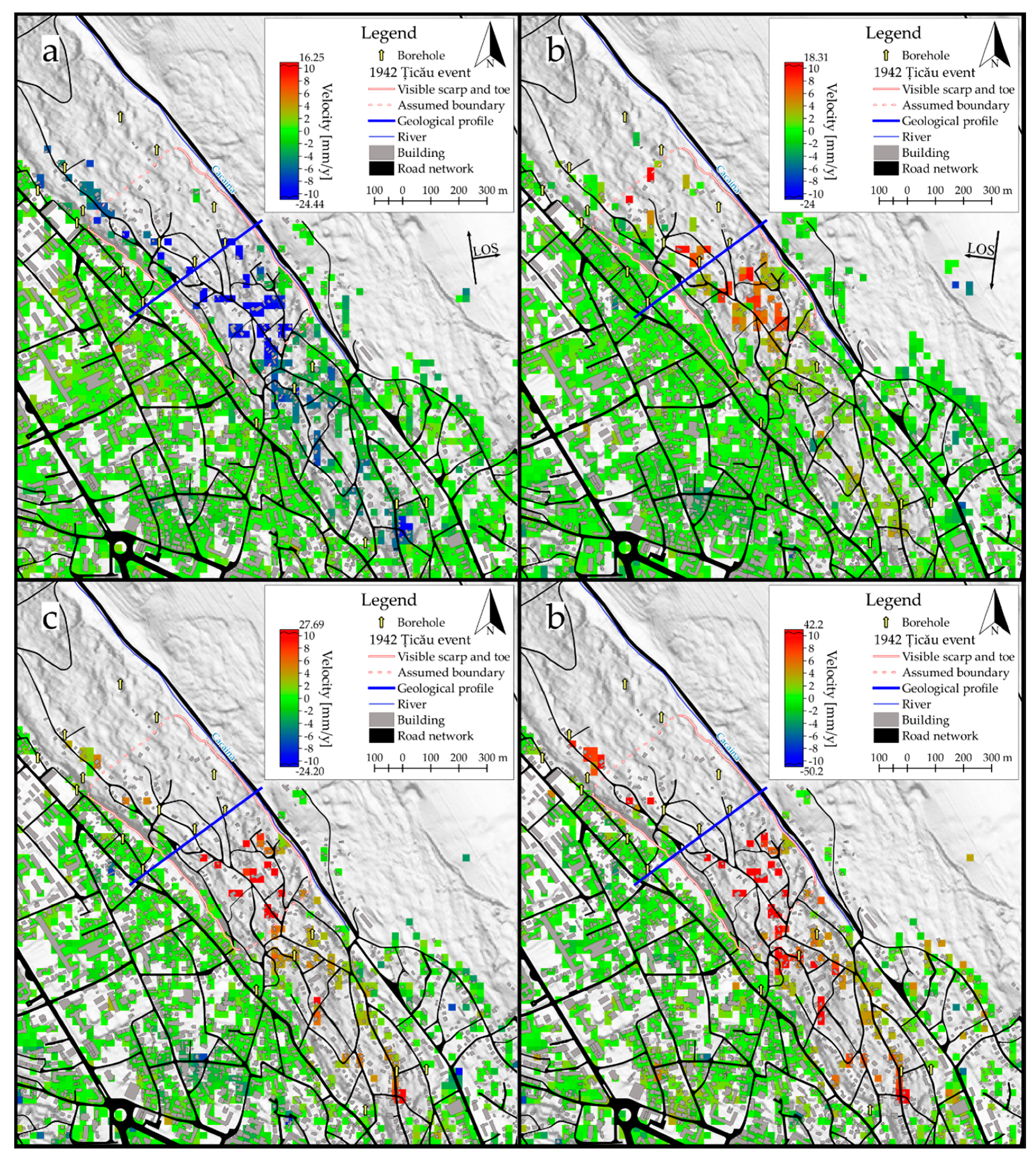
The results of Sentinel-1 SAR data analyzed with the PSI approach consist of mean velocity maps of single ground targets and time series of displacements. The velocities obtained over the entire study area range from −24.3 to +16.9 mm/year in the ascending orbit (Figure 6a) and from −24.2 to +12.9 mm/year in the descending one (Figure 6c). Positive values point out that the distance between target and sensor decreases over time, while the negative values suggest an increase of target-to-sensor distance as the target moves away from the satellite. The identified PSs in the descending orbit are 131,670, of which around 92.7% are stable points. In the ascending orbit were identified 125,022 PSs, of which 93.1% are stable. We consider as stable points those with a velocity between −2 and +2 mm/year in our analysis. This threshold was chosen based on the precision of MT-InSAR techniques [18,23,101] and on the specific observation on the PS results of Copou (stable plateaux) and Țicău area (instable hillslope) in [102].
The velocity of deformations recorded over the affected slopes ranges from ±7 mm/y to ±24 mm/y, measured along the satellite’s LOS, depending on the orbit’s geometry and the slope angle. North-eastern and eastern facing unstable slopes display positive changes in the descending orbit and negative values in the ascending orbit. Contrarily, south-western and western facing slopes show positive deformations in the ascending orbit or negative values in the descending one.
In the affected area of Țicău landslide, the mean velocities of the PSs have similar behavior with the above-described pattern, with high mean velocity values from ±7 mm/y up to ±24 mm/y (Figure 6b,d). The identified points are located mainly in the upper and the middle parts of the slope, as the lower part of the hillslope is covered by dense vegetation. Specifically, stable points are found at the top of the hill and above the landslide crown, while the unstable points are over the basal part of the landslide scarp and the depleted area.
The projected velocities along the slope show (Figure 7) similar patterns with the 1D velocities. The up and E-W components also confirm the conclusions obtained from the ascendent and descendent 1D velocities. Interestingly, these components are not as noisy as 1D data, the landslided hillslope being distinguishable from the adjacent stable hilltop. In the same time, coverage is lost because some points from the ascendent and descendent orbits are not in close proximity.
In the case of ENVISAT and ERS-1/2 SAR data, analyzed with the SBAS technique, the results are relatively poor compared to Sentinel 1 outputs, especially for the ERS-1/2 dataset where the low coherence of the signal significantly reduced the spatial information. The mean velocity map of the ENVISAT ascending dataset (Figure 6e,f) shows values ranging from −4 to −9 mm/year over the investigated event, and it confirms the continuous slow-moving state of the landslide. Due to the much better results of the Sentinel 1 datasets, we will focus our analysis on these results.
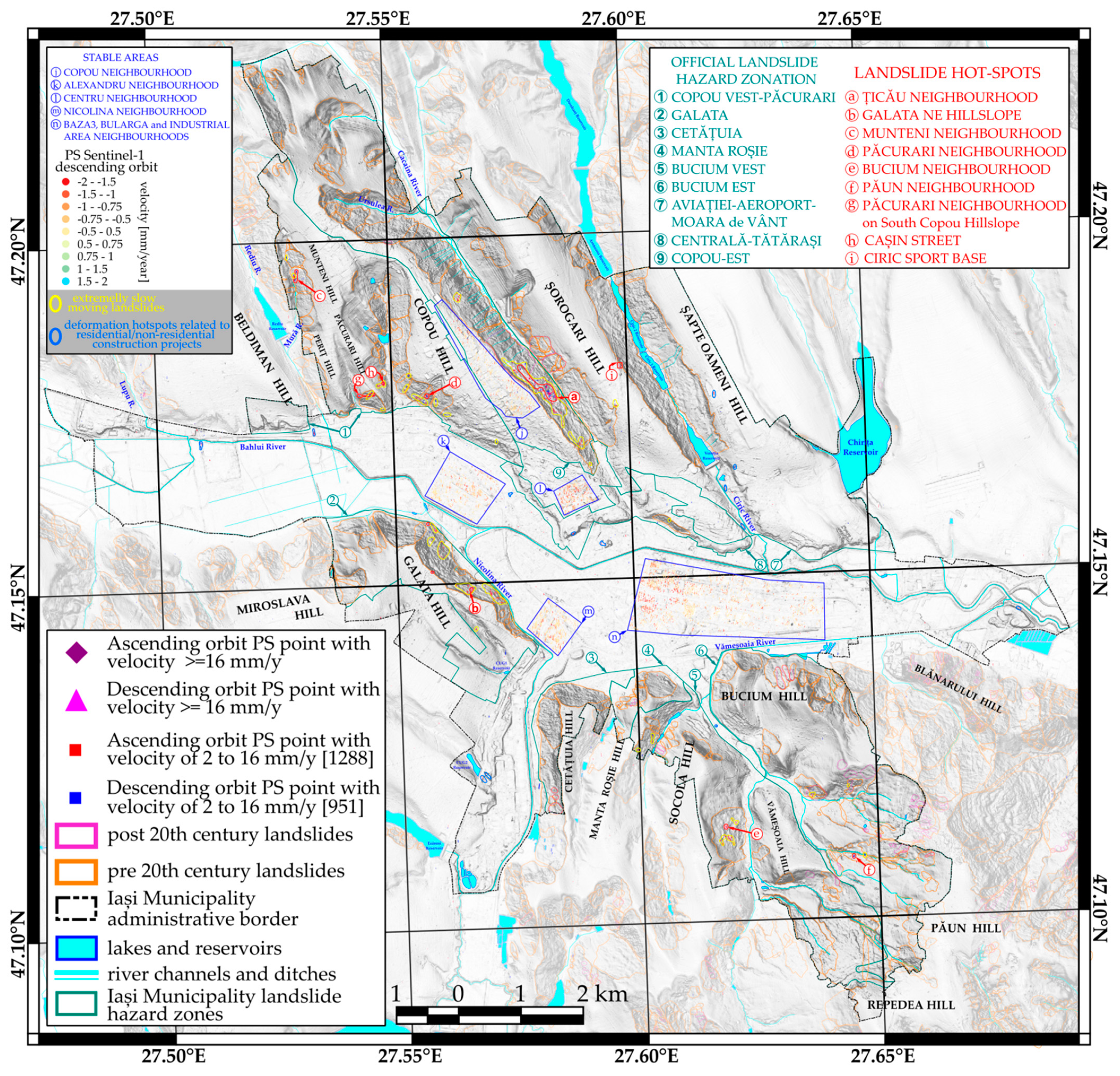
The Sentinel 1 SAR data processing allows the detection of landslides’ affected areas, updating and improving the available database, and monitoring the critical areas (Figure 6a,c). Most of the detected deformations overlay the landslide-affected areas within the landslide hazard zonation of Iași Municipality delineated by the Iași Municipality Administration (green polygons in Figure 8) and which cover 61.45% of the city surface. Seven out of the nine hazard zones delineated by the Iași Municipality Administration are affected by slope displacements.
The availability of both orbits, ascending and descending, improves our results’ reliability through cross-validation of the measurements obtained by the first geometry with the results of the second one and by the possibility to compute the components of the LOS displacement. Knowing that the Țicău landslide is sliding from southwest to northeast, we measure negative velocities in the ascending geometry while the descending records are positive (Figure 6).
The statistical post-processing of the SAR velocity pinpoints the present-day clusters of displacements related to active or dormant landslides mapped by [62,79] (Figure 8–orange and magenta polygons). We considered the empirical thresholds of [63,103] for landslide velocity to classify the rate of movement of the detected scatterers as follows: >16 mm/year are the velocities of very slow landslides that require maintenance, while in contrast, velocity <16 mm/year is characteristic of extremely slow landslides. Hence, two clusters of moving points with a velocity higher than 16 mm/year arguably classify as very slow-moving landslides located on hazard zones 9 and 2 of Figure 8.
Specifically, these clusters of displacement that we consider hot-spots of landslide activity are the red polygons in Figure 8 over the Țicău Neighborhood, in the North-Eastern side of Copou Hill and the NE hillslope of Galata Neighborhood. As highlighted in Figure 8, some other localized scatterers with similar velocities of the same class are associated with the construction of recent residential buildings over existing landslides. Such areas include the Munteni Neighborhood on the Western Copou Hillslope between Viticultori and Dealul Zorilor streets–hot-spot c; Păcurari Neighborhood on the S Copou Hill between Șipoțel and Cazărmilor streets–hot-spot d; Bucium Neighborhood on the E Socola hillslope between Mihail Galino and Margareta Baciu streets–hot-spot e; W Păun hillslope between Ciprian Porumbescu and Păun streets–hot-spot f. Other cases are associated with site-specific activities occurring over the hillslopes (e.g., Păcurari Neighborhood on S Copou hillslope, an area with intense activity due to the new houses built between Iancu Flondor, Nicolae Oblu and Bucovina streets–hot-spot g; Cașin street–hot-spot h; Ciric Sports Base built on an excavation site upslope the landslide scarp–hot-spot i).
The other areas that show ground deformations are classified as extremely slow-moving landslides. As the lower boundary of this class, we considered the 2 mm/year threshold representative for the investigated area. In our analysis, areas with velocities lower than 2 mm/year, classified as relatively stable, are located on the plateaus of the hills (Figure 8–stable areas j and l) and floodplains (Figure 8–stable areas k, m, and n).
The use of the Multi-temporal InSAR techniques enables the possibility to discriminate between the landslide-induced deformations over large areas from the isolated cases unrelated to the process. The former case is associated with the mapped landslide (Figure 8–the yellow polygons), while the latter relates to single or clusters of buildings located on slopes unaffected by landslides (red and blue squares not included in the yellow polygons in Figure 8). Other deformation hot-spots, usually on floodplains, are associated with residential or non-residential planning projects (blue polygons in Figure 8). We used the Mann-Kendall test to compute the trend for all the PS points in both ascending and descending orbit to discriminate between these hot-spots. Only the PS points with MK test p-value smaller than 0.0000005 (a trend is present) and a slope of the linear trend higher/smaller (depending on the orbit geometry) than 0.15/−0.15 were selected (trend present with a slope that indicates consistent deformation). Thus, were sorted out 1288 points in the ascending orbit and 951 points in the descending orbit (red and blue squares in Figure 8). The remaining points are classified as extremely slow-moving landslides delineated by the yellow boundary or isolated instabilities seen as single features in Figure 8.
The Bucium East Hazard Zone (hazard zone 6) is one of the city’s growing neighborhoods currently characterized by the expansion of the residential buildings. It has one very slow-moving landslide hot-spot and three extremely slow-moving landslides located over the previously mapped landslides. The Bucium West Hazard Zone (hazard zone 5) has one very slow-moving landslide hot-spot and four extremely slow-moving landslide hot-spots, similar to Bucium East Hazard Zone. The Galata Hazard Zone (hazard zone 2) has three hot-spots of very slow-moving landslides and six hot-spots of extremely slow-moving landslides. Most of them are on the NW hillslope of Galata Hill, where many residential buildings exist. The Copou West-Păcurari Hazard Zone (hazard zone 1) has four hot-spots of very slow-moving landslides and eleven hot-spots of extremely slow-moving landslides, known as recent landslides, and inhabited by the neighborhood’s community. The Copou East Hazard Zone (hazard zone 9) has the largest hot-spot identified within a slow-moving landslide and four hot-spots of extremely slow-moving landslide hot-spots. The Aviației-Airport-Moara de Vânt Hazard Zone (hazard zone 7) has one slow-moving deformation hot-spot and three hot-spots of extremely slow-moving landslides, the Central-Tătărași Hazard Zone (hazard zone 8) has only one hot-spot associated with extremely slow-moving landslides, and the other two hazard zones, namely the Cetățuia and Manta Roșie Hazard Zones (hazard zones 3 and 4) do not present landslide-related deformation hot-spots.
Based on the PS time series displacements, we can argue the sensitivity of slope dynamics to rainfall. The evolution pattern of the PS measurements over Țicău landslide is defined by trends associated with accelerating or decelerating periods (Figure 9). The displacements recorded during the investigated period confirm that Țicău landslide is active with rates of displacements that exhibit different trends separated by generalized breakpoints for the considered PS points.
The analysis of precipitation series indicates for the years 2014, 2016, and 2017 rainy springs and summers (both daily and as 30 days cumulative rainfall), while 2015 is drier during all seasons. In this context, the displacement trend decelerates from 2014 to 2015 and accelerates again during 2016. The location of the trend breakpoints (the rug plots from Figure 9) is consistent across all the PS for the spring 2015 and autumn 2016 trend changes. While there is no groundwater monitoring in the study area, and considering that groundwater response to rainfall is susceptible to a time delay [104], our interpretation of rainfall’s influence on displacement through groundwater recharge is the most probable. The complexity of the topography (roads, embankments, built surfaces) in the study area could explain the multiple breakpoints of the displacement trend during 2015 and 2016. That explains why some of the surface scatterers have a different sliding response in time.
The displacement behavior related to the distribution of the daily and the cumulative rainfall amount shows that prolonged rainfalls of medium intensity and two to three weeks long are much more significant for displacements initiation and acceleration compared to heavy rainfalls. Even though the short period of heavy rainfalls, of about one to two days, produces a more significant total amount of precipitation, it mainly occurs during drought periods, and due to the high intensity, the runoff of the water is more significant than the infiltration. In this context, PS displacements can be monitored together with the rainfall time series to search for increasing displacement trends that might indicate a possible reactivation event. The reactivation of 1942 is one such example that took place during the spring season. In that case, the landslide reactivation occurred due to the high accumulated amounts of precipitation. The rainy period started in the previous year’s autumn and continued in the spring of the year after coupled with the snow melting. These factors led to the soil’s complete saturation due to the water level increase and finally to the landslide triggering.

4.2. Numerical Simulations

We carried out a parametric study to verify the possible changes of landslide dynamics due to variations in the material properties and optimize our model. In this way, we reduce the uncertainty of the input data and minimize our assumptions to set up a more realistic model. In the simulations, we stressed the landslide unit (Layer 6—Landslide debris) because the displacements expected to occur are within this layer as they have been detected on the surface through MT-InSAR techniques and field evidence as well. We also took into account the water level measured during the execution of the boreholes even though it is susceptive to temporal depth variations. Thus, we performed several trial-and-error simulations to assess the response of the landslided material to the variation of parameter values. Although the properties are only slightly changed, the landslide behavior varies significantly.
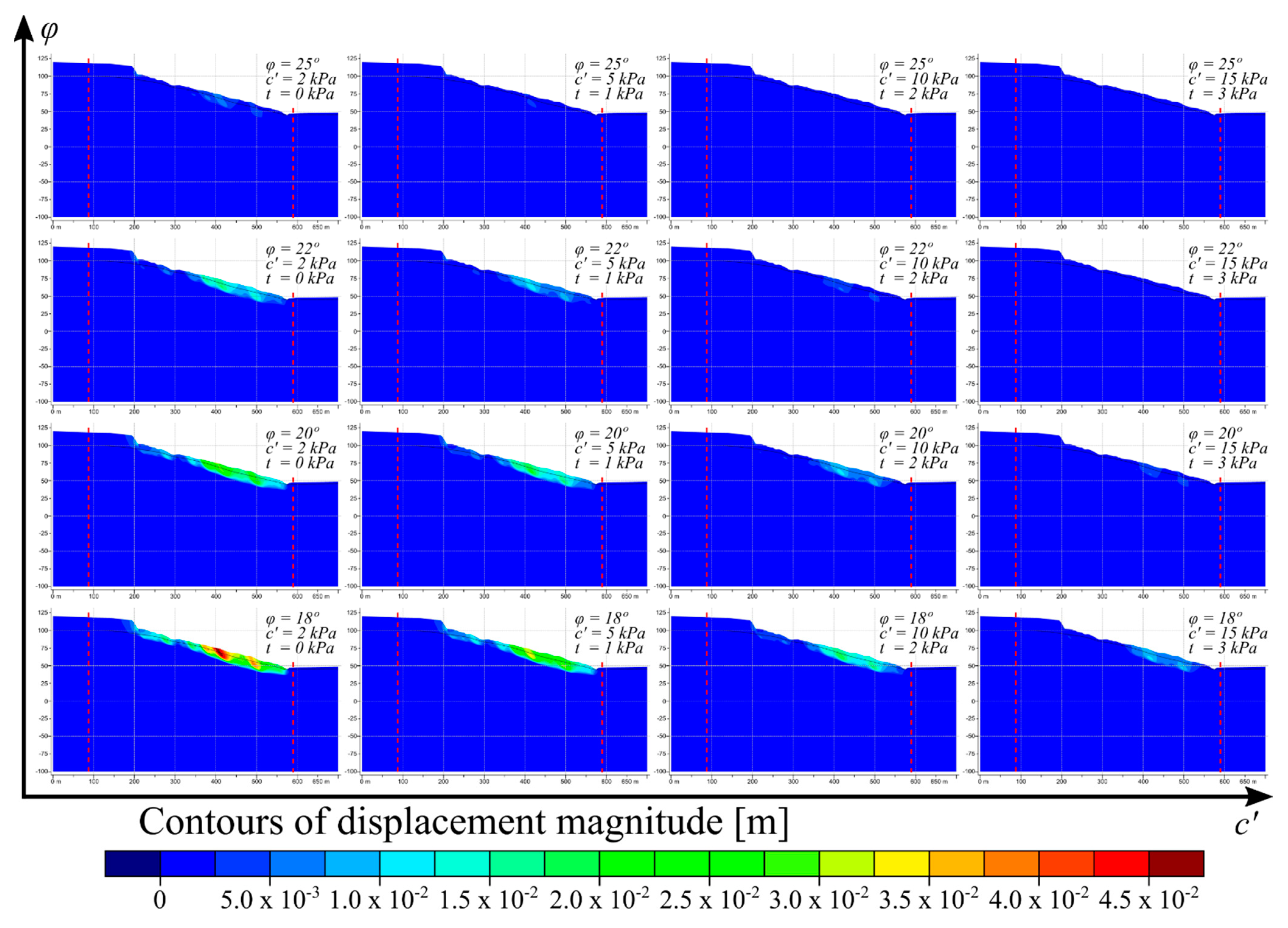
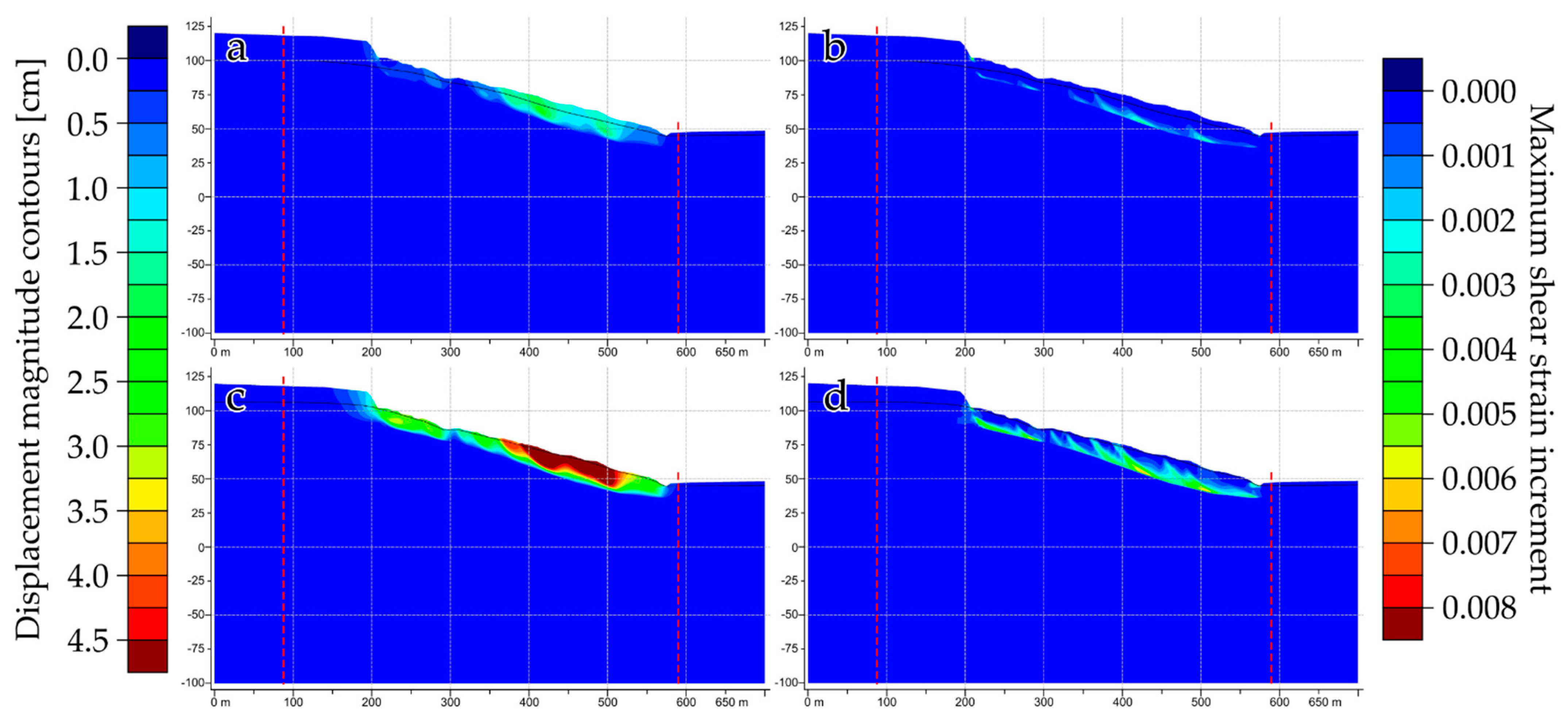
In terms of displacement magnitude (Figure 10), the model behaves consistently with the increment of material properties values. Specifically, by increasing the values of friction angle (ϕ) and the effective cohesion (c′) of material, the total displacements recorded by the model are decreasing. The simulation considered representative for the investigated landslide (ϕ = 20°, c′ = 5 kPa, t = 1 kPa) records displacements of a maximum of 2.5 cm and points out the middle sector of the slope as the most prone to deformations, compared to the upper and lower ones. These results significantly increase our understanding of the landslide in-depth behavior and sliding mechanism and can be used as prior information for future stabilization and development works.
Analyzing the displacement magnitude field, the middle sector of the slope results as the most active part of the landslide regardless of the scenario. The displacement magnitude history of some points distributed along the landslide body (Figure 11) supports the described behavior also. Moreover, the behavior of in-depth history points indicates higher displacements as we get closer to the surface.
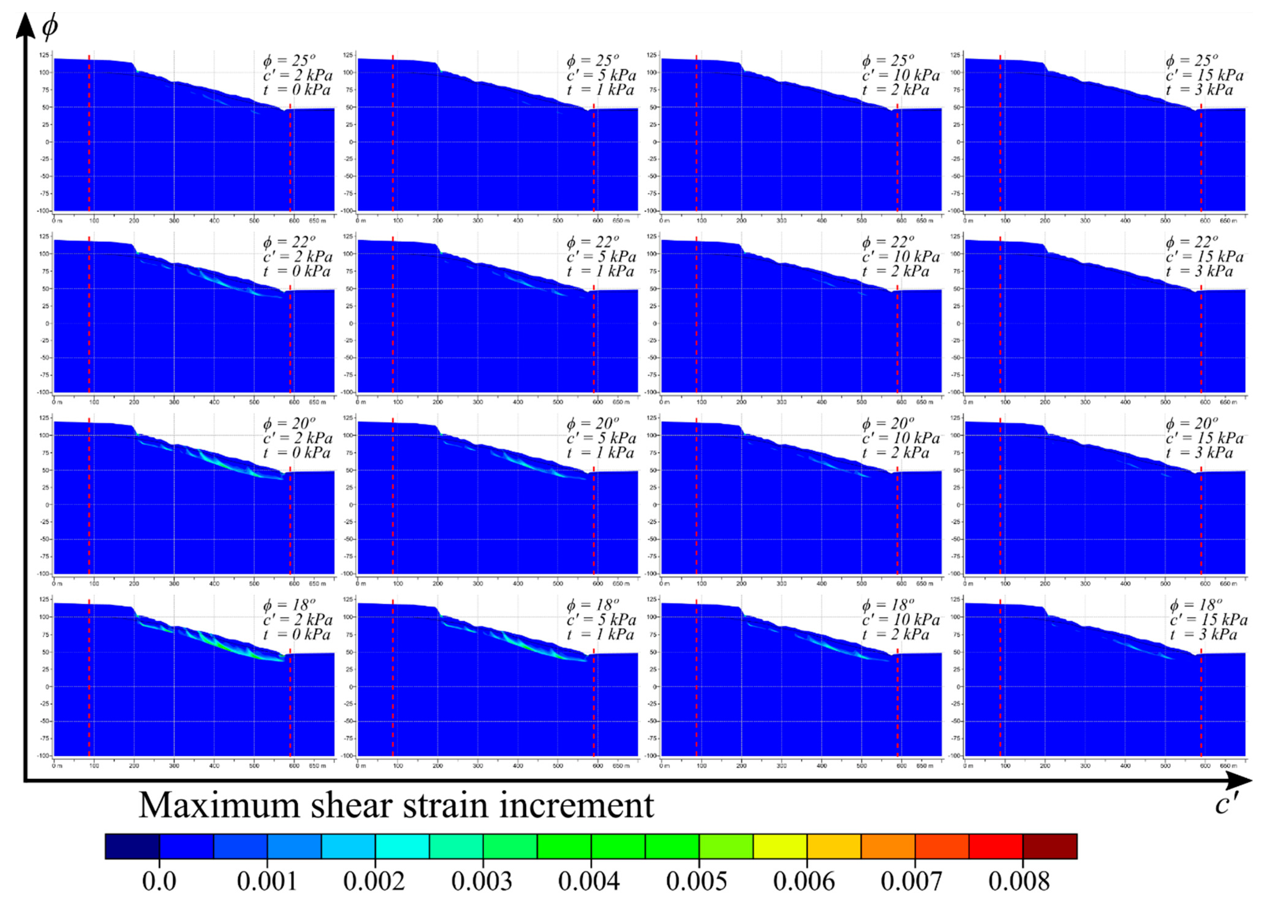
To determine the landslide typology and mechanism, we used the maximum shear strain increment, which is a good indicator of the failure mechanism [105]. The identified shearing zones are associated with the sliding surface, the main and secondary scarps along the landslide body (Figure 12). The secondary scarps increase in magnitude after they are subjected to the water level increase. In fact, in conditions of high-water level, similar to the 1942 reactivation, both magnitude of displacements and maximum shear strain increment significantly increased compared to the scenario where the water table was considered the one measured in the boreholes (Figure 13). In this“worst” scenario, the total displacements are much higher than 4.5 cm, reaching a maximum of 9 cm in the middle sector. Based on the maximum shear strain increment, the sliding surface and the secondary scarps aggravate, and the main scarp is susceptible to reactivation.
Although it is not possible to directly compare the velocities measured through interferometry techniques and the displacements obtained in the numerical simulations, we observe that the results of both methods point out the median part of the landslide as the most active sector.
The advantage of numerical modeling consists of the continuous displacements field that we obtain, while in the case of PS measurements, we get discontinuous data but are highly accurate. On the other hand, performing numerical modeling requires as many in-situ measurements as possible. The lack of such data limits the time-dependent modeling to observe the evolution of displacements, comparable to the temporal displacement series of MT-InSAR results. Because of this, we performed our simulations using the Mohr-Coulomb elastoplastic model. The results give us information about the displacements’ behavior, their magnitude, and the sliding mechanism.

5. Discussion

5.1. MT-InSAR Outputs and Numerical Simulations

The investigated Țicău landslide behaves as a very slow-moving translational slide from SW to NE direction. The typology of the landslide is concluded based on the simulations we carried out. The maximum shear strain increment reveals the failure surface and the presence of several minor scarps that accentuate as the water level increases. The mean annual velocities, depicted through the processing of SAR data, measure from 10 to 20 mm/year over the landslide body. Even though the measurements are in the Line of Sight of the satellite, it is a good indicator of the deformations that occur in the area, especially the ascending orbit case. Due to the satellite’s flight path and the sliding direction of the landslide, the measured displacement values are close to the actual displacements that occur over the landslide.
Simulations of slope displacements reveal the landslide mechanism and allow the investigation of multiple scenarios to assess the process’s dynamics properly. The pattern of displacements is consistent with the simulations we performed, intending to reduce the uncertainties related to the data we used.
The results of both used techniques are in agreement and reveal that the middle sector of the slope is the most active part of the landslide. The analysis of the displacement time series indicates that acceleration periods take place during long-term rainfalls. The simulations also enhance this aspect, as they clearly show an increase of total displacements of the landslide and a much more prominent sliding surface.
The numerical modeling results regarding the displacement pattern of the landslide argue the landslide typology as a shallow translational body. This outcome is contrasting to what previous studies suggest, a deep rotational landslide [100]. The borehole information on which these previous conclusions are based (i.e., granulometry, unit weight) is deficient and unconvincing. They are evaluated only from an uncomplete geotechnical point of view without considering the stratigraphic and geomorphologic data (bedrock, surficial deposits, and landslide sliding surface).
A better investigation of the subsurface is necessary to improve the model from a geophysical and geotechnical point of view and in-situ measurements by installing necessary instrumentations. These will allow the use of an advanced model that considers the materials’ viscosity characteristics and thus proceed to a time-dependent creep analysis.

5.2. Benefits and Limitations of the Analysis

To carry out our investigation, we exploited both the employed techniques at best by integrating their results to overcome the flaws of one method with the strengths of the other. Regarding the MT-InSAR analysis, the main problem encountered during the image processing is related to dense vegetation and loss of coherence for the analyzed period. When coupled with the lack of images, this leads to substantial loss of spatial information, as in the ERS and ENVISAT data stacks. The basal sector of the Țicău landslide is covered by forest, and we can notice that it was not possible to detect deformations over that area, not even with Sentinel-1. However, we overcame this problem using numerical simulations, which indicate that the slope’s basal sector is also moving even though it is not as active as the middle part.
Due to the lack of reliable in-situ data for our numerical modeling, we had to make some assumptions worth mentioning to complete our material properties database. We considered the landslide debris as a singular, homogenous entity. In reality, the remolded material most likely has lithological and implicitly geotechnical variations, both in-depth and laterally. To reduce the uncertainty of made assumptions, we performed trial-and-error simulations of various combinations of the intrinsic properties, showing that these assumptions are relevant and justified.
The groundwater level we employed in our modeling is the measured one during drilling, which might be at its lowest depths, considering that the boreholes were executed during the summer. We should keep in mind that it has seasonal fluctuations, manifesting as accelerations and decelerations of deformations, as suggested by the MT-InSAR measurements.
At the same time, in our analysis, we did not consider the anthropic implications such as the existence of the residential buildings that exert an additional load over the unstable body nor the already existing stabilization infrastructure, such as drainage system, retaining walls, and gabions at the base of the main scarp. About this aspect, it is necessary to get a detailed investigation about the type of building foundations, the year of construction, to evaluate the state of degradation, the height of buildings, the construction material.
However, the numerical modeling results are supported by MT-InSAR results and field information, indicating that the displacements obtained are consistent and validate our model. Further geophysical prospects will improve the geological model and will help to generate an improved numerical model that could better explain the spatial and temporal variations of the displacements patterns.
Nonetheless, our results prove that the use of MT-InSAR techniques and SAR data coupled with numerical simulations has the potential to deliver critical information about landslide processes in areas where the lack of in-situ data is the major shortcoming, not only in the well-investigated ones. The MT-InSAR provides data about the spatial extent and the displacements behavior in time, while the simulations give a better understanding of the landslide type and its mechanism and in-depth behavior. Their outcome is beneficial not only for the landslide monitoring and landslide hazard assessment but also as prior information for future planning and policy implementation.

6. Conclusions

The application of Multi-temporal SAR Interferometry techniques (MT-InSAR) and numerical modeling of slope failures in urban areas is a must in the current context of urban territorial expansion to successfully identify and monitor possible slope deformations that might threaten the infrastructure and people. For the case of Iași Municipality, the benefits of coupling MT-InSAR results (i.e., surface velocity maps) and slope numerical simulations allowed us: (1) to identify the potentially dangerous areas affected by slope instabilities; (2) to properly delimitate the extent of the active sector tampering the Țicău neighborhood’s integrity; (3) to monitor the landslide activity and its behavior related to the rainfall amount and water level changes; (4) to argue the landslide typology based on its velocity and failure mechanism.
The integration of InSAR and simulation results coupled with field surveys highly facilitates the characterization and improves our understanding of the landslide dynamics and evolution. Thus, we can say that Țicău landslide behaves as a very slow-moving landslide with a translational mechanism sliding from SW towards NE. The displacement pattern points out the middle sector of the slope as the most prone to deformations that are accelerating after extended periods of rainfall. The mean annual velocities over the landslide body vary from 10 mm/year to over 20 mm/year in the middle sector of the slope underlined by the material simulations. These outputs should be deemed as prospective and used as prior information to support the implementation of stabilization policies, as the local authorities recently approved funding for such strategies. Nonetheless, our results enhance the idea of integrating the results of MT-InSAR techniques and numerical modeling as it has the potential to be used in areas lacking ground measurements. Their capabilities to acquire and generate information about slope instabilities are valuable to assess the landslide hazard.
Future works include continuing the landslide monitoring using MT-InSAR techniques and, especially, improving the numerical model. To this end, we will consider the buildings and infrastructure that load the sliding material. There are plans to carry out shallow seismic surveys and electrical resistivity tomography (ERT) to increase the quality of in-situ data. The access to better data and knowledge will allow, in the long run, to model the entire slope and use an advanced viscous model to assess the time-dependent behavior of the landslide.

Author Contributions

Conceptualization, N.N., M.N. and M.F.; methodology, N.N.; software, N.N., M.F. and R.G.; validation, N.N., M.N., M.F., R.G., S.F. and P.R.; writing—original draft preparation, N.N.; writing—review and editing, N.N., M.N., M.F., R.G., S.F. and P.R. All authors have read and agreed to the published version of the manuscript.

Funding

In this work, Nicușor Necula was funded by the European Social Fund, through Operational Programme Human Capital 2014-2020, project number POCU/380/6/13/123623, project title “Ph.D. Students and Postdoctoral Researchers Prepared for the Labour Market” and Mihai Niculiță by the grant of Ministry of Research and Innovation CNCS-UEFISCDI, project number PN-III-P1-1.1-PD- 2016-0154, within PNCDI III.

Acknowledgments

We are grateful to Prut-Bârlad Water Administration, who provided us with the LIDAR data. We acknowledge the data providers in the ECA&D project (https://www.ecad.eu, accessed on 23 July 2021). Nicușor Necula and Mihai Niculiță have used the computational facilities given by the infrastructure provided through the POSCCE-O 2.2.1, SMIS-CSNR 13984-901, No. 257/28.09.2010 Project, CERNESIM (L4).

Conflicts of Interest

The authors declare no conflict of interest.

References

  1. Fastellini, G.; Radicioni, F.; Stoppini, A. The Assisi landslide monitoring: A multi-year activity based on geomatic techniques. Appl. Geomat. 2011, 3, 91–100. [Google Scholar] [CrossRef]
  2. Alexander, D. Urban landslides. Prog. Phys. Geogr. 1989, 13, 157–189. [Google Scholar] [CrossRef]
  3. Haque, U.; Blum, P.; da Silva, P.F.; Andersen, P.; Pilz, J.; Chalov, S.R.; Malet, J.P.; Auflič, M.J.; Andres, N.; Poyiadji, E.; et al. Fatal landslides in Europe. Landslides 2016, 13, 1545–1554. [Google Scholar] [CrossRef]
  4. Kjekstad, O.; Highland, L. Economic and Social Impacts of Landslides. In Landslides—Disaster Risk Reduction; Sassa, K., Canuti, P., Eds.; Springer: Berlin/Heidelberg, Germany, 2009; pp. 573–587. ISBN 978-3-540-69966-8. [Google Scholar]
  5. Schuster, R.L.; Fleming, R.W. Economic Losses and Fatalities Due to Landslides. Environ. Eng. Geosci. 1986, xxiii, 11–28. [Google Scholar] [CrossRef]
  6. Froude, M.J.; Petley, D.N. Global fatal landslide occurrence from 2004 to 2016. Nat. Hazards Earth Syst. Sci. 2018, 18, 2161–2181. [Google Scholar] [CrossRef] [Green Version]
  7. Petley, D.N. The global occurrence of fatal landslides in 2007. In Proceedings of the Geophysical Research Abstracts EGU General Assembly, Vienna, Austria, 13–18 April 2008; Volume 10, p. EGU2008-A-10487. [Google Scholar]
  8. Bamler, R.; Hartl, P. Synthetic aperture radar interferometry. Inverse Probl. 1998, 14, 54. [Google Scholar] [CrossRef]
  9. Rosen, P.A.; Hensley, S.; Joughin, I.R.; Li, F.K.; Madsen, S.N.; Rodriguez, E.; Goldstein, R.M. Synthetic aperture radar interferometry. Proc. IEEE 2000, 88, 333–382. [Google Scholar] [CrossRef]
  10. Bürgmann, R.; Rosen, P.A.; Fielding, E.J. Synthetic Aperture Radar Interferometry to Measure Earth’s Surface Topography and Its Deformation. Annu. Rev. Earth Planet. Sci. 2000, 28, 169–209. [Google Scholar] [CrossRef]
  11. Massonnet, D.; Feigl, K.L. Radar interferometry and its application to changes in the Earth’s surface. Rev. Geophys. 1998, 36, 441–500. [Google Scholar] [CrossRef] [Green Version]
  12. Lanari, R.; Fornaro, G.; Riccio, D.; Migliaccio, M.; Papathanassiou, K.P.; Moreira, J.R.; Schwäbisch, M.; Dutra, L.; Puglisi, G.; Franceschetti, G.; et al. Generation of digital elevation models by using SIR-C/X-SAR multifrequency two-pass interferometry: The etna case study. IEEE Trans. Geosci. Remote Sens. 1996, 34, 1097–1114. [Google Scholar] [CrossRef]
  13. Pizzi, A.; Pugliese, G. InSAR-DEM analyses integrated with geologic field methods for the study of long-term seismogenic fault behavior: Applications in the axial zone of the central Apennines (Italy). J. Seismol. 2004, 8, 313–329. [Google Scholar] [CrossRef]
  14. Krieger, G.; Moreira, A.; Fiedler, H.; Hajnsek, I.; Werner, M.; Younis, M.; Zink, M. TanDEM-X: A Satellite Formation for High-Resolution SAR Interferometry. IEEE Trans. Geosci. Remote. Sens. 2007, 45, 3317–3340. [Google Scholar] [CrossRef] [Green Version]
  15. Massonnet, D.; Rossi, M.; Carmona, C.; Adragna, F.; Peltzer, G.; Feigl, K.L.; Rabaute, T. The displacement field of the Landers earthquake mapped by radar interferometry. Nature 1993, 364, 138–142. [Google Scholar] [CrossRef]
  16. Tomiyama, N.; Koike, K.; Omura, M. Detection of topographic changes associated with volcanic activities of Mt. Hossho using D-InSAR. Adv. Sp. Res. 2004, 33, 279–283. [Google Scholar] [CrossRef]
  17. Kampes, B.M. Radar Interferometry: Persistent Scatterer Technique, 1st ed.; Springer: Dordrecht, The Netherlands, 2006; ISBN 978-1-4020-4576-9. [Google Scholar]
  18. Colesanti, C.; Wasowski, J. Investigating landslides with space-borne Synthetic Aperture Radar (SAR) interferometry. Eng. Geol. 2006, 88, 173–199. [Google Scholar] [CrossRef]
  19. Hanssen, R.F. Radar Interferometry, Data Interpretation and Error Analysis, 1st ed.; Springer: Dordrecht, The Netherlands, 2001; ISBN 978-0-7923-6945-5. [Google Scholar]
  20. Crosetto, M.; Monserrat, O.; Cuevas-González, M.; Devanthéry, N.; Crippa, B. Persistent Scatterer Interferometry: A review. ISPRS J. Photogramm. Remote Sens. 2016, 115, 78–89. [Google Scholar] [CrossRef] [Green Version]
  21. Wasowski, J.; Bovenga, F. Investigating landslides and unstable slopes with satellite Multi Temporal Interferometry: Current issues and future perspectives. Eng. Geol. 2014, 174, 103–138. [Google Scholar] [CrossRef]
  22. Ferretti, A.; Prati, C.; Rocca, F. Nonlinear Subsidence Rate Estimation Using Permanent Scatterers in Differential SAR Interferometry. IEEE Trans. Geosci. Remote Sens. 2000, 38, 2202–2212. [Google Scholar] [CrossRef] [Green Version]
  23. Ferretti, A.; Prati, C.; Rocca, F. Permanent scatterers in SAR interferometry. IEEE Trans. Geosci. Remote Sens. 2001, 39, 8–20. [Google Scholar] [CrossRef]
  24. Berardino, P.; Fornaro, G.; Lanari, R.; Sansosti, E. A New Algorithm for Surface Deformation Monitoring based on Small Baseline Differential SAR Interferograms. IEEE Trans. Geosci. Remote Sens. 2002, 40, 2375–2383. [Google Scholar] [CrossRef] [Green Version]
  25. Cascini, L.; Fornaro, G.; Peduto, D. Advanced low- and full-resolution DInSAR map generation for slow-moving landslide analysis at different scales. Eng. Geol. 2010, 112, 29–42. [Google Scholar] [CrossRef]
  26. Kalia, A.C. Classification of Landslide Activity on a Regional Scale Using Persistent Scatterer Interferometry at the Moselle Valley (Germany). Remote Sens. 2018, 10, 1880. [Google Scholar] [CrossRef] [Green Version]
  27. Zhao, F.; Mallorqui, J.J.; Iglesias, R.; Gili, J.A.; Corominas, J. Landslide Monitoring Using Multi-Temporal SAR Interferometry with Advanced Persistent Scatterers Identification Methods and Super High-Spatial Resolution TerraSAR-X Images. Remote Sens. 2018, 10, 921. [Google Scholar] [CrossRef] [Green Version]
  28. Béjar-Pizarro, M.; Notti, D.; Mateos, R.M.; Ezquerro, P.; Centolanza, G.; Herrera, G.; Bru, G.; Sanabria, M.; Solari, L.; Duro, J.; et al. Mapping Vulnerable Urban Areas Affected by Slow-Moving Landslides Using Sentinel-1 InSAR Data. Remote Sens. 2017, 9, 876. [Google Scholar] [CrossRef] [Green Version]
  29. Notti, D.; Herrera, G.; Bianchini, S.; Meisina, C.; García-Davalillo, J.C.; Zucca, F. A methodology for improving landslide PSI data analysis. Int. J. Remote Sens. 2014, 35, 2186–2214. [Google Scholar] [CrossRef]
  30. Del Ventisette, C.; Righini, G.; Moretti, S.; Casagli, N. Multitemporal landslides inventory map updating using spaceborne SAR analysis. Int. J. Appl. Earth Obs. Geoinf. 2014, 30, 238–246. [Google Scholar] [CrossRef] [Green Version]
  31. Dong, J.; Zhang, L.; Li, M.; Yu, Y.; Liao, M.; Gong, J.; Luo, H. Measuring precursory movements of the recent Xinmo landslide in Mao County, China with Sentinel-1 and ALOS-2 PALSAR-2 datasets. Landslides 2018, 15, 135–144. [Google Scholar] [CrossRef]
  32. Moretto, S.; Bozzano, F.; Esposito, C.; Mazzanti, P.; Rocca, A. Assessment of Landslide Pre-Failure Monitoring and Forecasting Using Satellite SAR Interferometry. Geosciences 2017, 7, 36. [Google Scholar] [CrossRef] [Green Version]
  33. Shirani, K.; Pasandi, M. Detecting and monitoring of landslides using persistent scattering synthetic aperture radar interferometry. Environ. Earth Sci. 2019, 78, 42. [Google Scholar] [CrossRef]
  34. Kang, Y.; Zhao, C.; Zhang, Q.; Lu, Z.; Li, B. Application of InSAR Techniques to an Analysis of the Guanling Landslide. Remote Sens. 2017, 9, 1046. [Google Scholar] [CrossRef] [Green Version]
  35. Bonì, R.; Bordoni, M.; Colombo, A.; Lanteri, L.; Meisina, C. Landslide state of activity maps by combining multi-temporal A-DInSAR (LAMBDA). Remote Sens. Environ. 2018, 217, 172–190. [Google Scholar] [CrossRef]
  36. Fiaschi, S.; Mantovani, M.; Frigerio, S.; Pasuto, A.; Floris, M. Testing the potential of Sentinel-1A TOPS interferometry for the detection and monitoring of landslides at local scale (Veneto Region, Italy). Environ. Earth Sci. 2017, 76, 492. [Google Scholar] [CrossRef]
  37. Tessari, G.; Floris, M.; Pasquali, P. Phase and amplitude analyses of SAR data for landslide detection and monitoring in non-urban areas located in the North-Eastern Italian pre-Alps. Environ. Earth Sci. 2017, 76, 1–11. [Google Scholar] [CrossRef]
  38. Esposito, G.; Marchesini, I.; Mondini, A.C.; Reichenbach, P.; Rossi, M.; Sterlacchini, S. A spaceborne SAR-based procedure to support the detection of landslides. Nat. Hazards Earth Syst. Sci. 2020, 20, 2379–2395. [Google Scholar] [CrossRef]
  39. Liu, S.; Segoni, S.; Raspini, F.; Yin, K.; Zhou, C.; Zhang, Y.; Casagli, N. Satellite InSAR as a New Tool for the Verification of Landslide Engineering Remedial Works at the Regional Scale: A Case Study in the Three Gorges Resevoir Area, China. Appl. Sci. 2020, 10, 6435. [Google Scholar] [CrossRef]
  40. Reyes-Carmona, C.; Barra, A.; Galve, J.; Monserrat, O.; Pérez-Peña, J.; Mateos, R.; Notti, D.; Ruano, P.; Millares, A.; López-Vinielles, J.; et al. Sentinel-1 DInSAR for Monitoring Active Landslides in Critical Infrastructures: The Case of the Rules Reservoir (Southern Spain). Remote Sens. 2020, 12, 809. [Google Scholar] [CrossRef] [Green Version]
  41. Intrieri, E.; Raspini, F.; Fumagalli, A.; Lu, P.; Del Conte, S.; Farina, P.; Allievi, J.; Ferretti, A.; Casagli, N. The Maoxian landslide as seen from space: Detecting precursors of failure with Sentinel-1 data. Landslides 2018, 15, 123–133. [Google Scholar] [CrossRef] [Green Version]
  42. Sun, Q.; Hu, J.; Zhang, L.; Ding, X. Towards Slow-Moving Landslide Monitoring by Integrating Multi-Sensor InSAR Time Series Datasets: The Zhouqu Case Study, China. Remote Sens. 2016, 8, 908. [Google Scholar] [CrossRef] [Green Version]
  43. Frattini, P.; Crosta, G.B.; Rossini, M.; Allievi, J. Activity and kinematic behaviour of deep-seated landslides from PS-InSAR displacement rate measurements. Landslides 2018, 15, 1053–1070. [Google Scholar] [CrossRef]
  44. Dong, J.; Zhang, L.; Tang, M.; Liao, M.; Xu, Q.; Gong, J.; Ao, M. Mapping landslide surface displacements with time series SAR interferometry by combining persistent and distributed scatterers: A case study of Jiaju landslide in Danba, China. Remote Sens. Environ. 2018, 205, 180–198. [Google Scholar] [CrossRef]
  45. Bovenga, F.; Wasowski, J.; Nitti, D.O.; Nutricato, R.; Chiaradia, M.T. Using COSMO/SkyMed X-band and ENVISAT C-band SAR interferometry for landslides analysis. Remote Sens. Environ. 2012, 119, 272–285. [Google Scholar] [CrossRef]
  46. Calò, F.; Ardizzone, F.; Castaldo, R.; Lollino, P.; Tizzani, P.; Guzzetti, F.; Lanari, R.; Angeli, M.-G.; Pontoni, F.; Manunta, M. Enhanced landslide investigations through advanced DInSAR techniques: The Ivancich case study, Assisi, Italy. Remote Sens. Environ. 2014, 142, 69–82. [Google Scholar] [CrossRef] [Green Version]
  47. Bovenga, F.; Nutricato, R.; Refice, A.; Wasowski, J. Application of multi-temporal differential interferometry to slope instability detection in urban/peri-urban areas. Eng. Geol. 2006, 88, 218–239. [Google Scholar] [CrossRef]
  48. Duncan, J.M. State of the Art: Limit Equilibrium and Finite-Element Analysis of Slopes. J. Geotech. Eng. 1996, 122, 577–596. [Google Scholar] [CrossRef]
  49. Abramson, L.W.; Lee, T.S.; Sharma, S.; Boyce, G.M. Slope Stability and Stabilization Methods, 2nd ed.; John Wiley & Sons, Inc.: New York, NY, USA, 2002; ISBN 0-471-38493-3. [Google Scholar]
  50. Wei, Z.L.; Wang, D.F.; Xu, H.D.; Sun, H.Y. Clarifying the effectiveness of drainage tunnels in landslide controls based on high-frequency in-site monitoring. Bull. Eng. Geol. Environ. 2020, 79, 3289–3305. [Google Scholar] [CrossRef]
  51. Troncone, A.; Pugliese, L.; Lamanna, G.; Conte, E. Prediction of rainfall-induced landslide movements in the presence of stabilizing piles. Eng. Geol. 2021, 288, 106143. [Google Scholar] [CrossRef]
  52. Castaldo, R.; Tizzani, P.; Lollino, P.; Calò, F.; Ardizzone, F.; Lanari, R.; Guzzetti, F.; Manunta, M. Landslide Kinematical Analysis through Inverse Numerical Modelling and Differential SAR Interferometry. Pure Appl. Geophys. 2015, 172, 3067–3080. [Google Scholar] [CrossRef]
  53. De Novellis, V.; Castaldo, R.; Lollino, P.; Manunta, M.; Tizzani, P. Advanced Three-Dimensional Finite Element Modeling of a Slow Landslide through the Exploitation of DInSAR Measurements and in Situ Surveys. Remote Sens. 2016, 8, 670. [Google Scholar] [CrossRef] [Green Version]
  54. Cevasco, A.; Termini, F.; Valentino, R.; Meisina, C.; Bonì, R.; Bordoni, M.; Chella, G.P.; De Vita, P. Residual mechanisms and kinematics of the relict Lemeglio coastal landslide (Liguria, northwestern Italy). Geomorphology 2018, 320, 64–81. [Google Scholar] [CrossRef]
  55. Zhou, W.; Li, S.; Zhou, Z.; Chang, X. InSAR Observation and Numerical Modeling of the Earth-Dam Displacement of Shuibuya Dam (China). Remote Sens. 2016, 8, 877. [Google Scholar] [CrossRef] [Green Version]
  56. Zhang, F.; Yang, T.; Li, L.; Wang, Z.; Xiao, P. Cooperative monitoring and numerical investigation on the stability of the south slope of the Fushun west open-pit mine. Bull. Eng. Geol. Environ. 2019, 78, 2409–2429. [Google Scholar] [CrossRef]
  57. López-Vinielles, J.; Fernández-Merodo, J.A.; Ezquerro, P.; García-Davalillo, J.C.; Sarro, R.; Reyes-Carmona, C.; Barra, A.; Navarro, J.A.; Krishnakumar, V.; Alvioli, M.; et al. Combining Satellite InSAR, Slope Units and Finite Element Modeling for Stability Analysis in Mining Waste Disposal Areas. Remote Sens. 2021, 13, 2008. [Google Scholar] [CrossRef]
  58. Notti, D.; Wrzesniak, A.; Dematteis, N.; Lollino, P.; Fazio, N.L.; Zucca, F.; Giordan, D. A multidisciplinary investigation of deep-seated landslide reactivation triggered by an extreme rainfall event: A case study of the Monesi di Mendatica landslide, Ligurian Alps. Landslides 2021, 18, 2341–2365. [Google Scholar] [CrossRef]
  59. Hu, X.; Bürgmann, R.; Schulz, W.H.; Fielding, E.J. Four-dimensional surface motions of the Slumgullion landslide and quantification of hydrometeorological forcing. Nat. Commun. 2020, 11, 2792. [Google Scholar] [CrossRef] [PubMed]
  60. Bălteanu, D.; Micu, M.; Jurchescu, M.; Malet, J.; Sima, M.; Kucsicsa, G.; Dumitrică, C.; Petrea, D.; Mărgărint, M.C.; Bilaşco, Ş.; et al. National-scale landslide susceptibility map of Romania in a European methodological framework. Geomorphology 2020, 371, 107432. [Google Scholar] [CrossRef]
  61. Jaedicke, C.; Van Den Eeckhaut, M.; Nadim, F.; Hervás, J.; Kalsnes, B.; Vangelsten, B.V.; Smith, J.T.; Tofani, V.; Ciurean, R.; Winter, M.G.; et al. Identification of landslide hazard and risk ‘hot-spots’ in Europe. Bull. Eng. Geol. Environ. 2014, 73, 325–339. [Google Scholar] [CrossRef] [Green Version]
  62. Necula, N.; Niculiță, M. Landslide reactivation susceptibility modeling in Iași Municipality. Revista de Geomorfologie 2017, 19, 101–117. [Google Scholar] [CrossRef]
  63. Hungr, O.; Leroueil, S.; Picarelli, L. The Varnes classification of landslide types, an update. Landslides 2014, 11, 167–194. [Google Scholar] [CrossRef]
  64. Ionesi, L. Geologia Unităților de Platformă și a Orogenului Nord-Dobrogean; Editura Tehnică: Bucharest, Romania, 1994; ISBN 973-31-0531-7. [Google Scholar]
  65. Brânzila, M. Geologia Părții Sudice a Câmpiei Moldovei, 1st ed.; Corson: Iași, Romania, 1999; ISBN 973-99043-3-X. [Google Scholar]
  66. Mutihac, V.; Mutihac, G. The Geology of Romania within the Central East-European Geostructural Context, 1st ed.; Editura Didactică și Pedagogică, R.A.: Bucharest, Romania, 2010; ISBN 978-973-30-2686-0. [Google Scholar]
  67. Băcăuanu, V. Evoluția văilor din Podișul Moldovenesc. In Realizări în Geografia României; Editura Științifică: Bucharest, Romania, 1973; pp. 227–235. [Google Scholar]
  68. Niculiță, M. A classification schema for structural landforms of the Moldavian platform (Romania). In Proceedings of the Geomorphometry 2011: Five days of Digital Terrain Analysis, University of Southern California, Redlands, CA, USA, 7–11 September 2011; pp. 129–132. [Google Scholar]
  69. Ioniță, I. Relieful de Cueste din Podișul Moldovei; Editura Corson: Iași, Romania, 2000; ISBN 9739825931. [Google Scholar]
  70. Schram, M.; Pantazică, M.; Martiniuc, C. Aspecte hidrogeologice din zona Municipiului Iași și împrejurimi. An. Științifice Ale Univ. Al. I. Cuza Din Iași (Ser. Nouă) Secțiunea II b Geol. 1977, 23, 107–113. [Google Scholar]
  71. Ionesi, L.; Ionesi, B.; Roşca, V.; Lungu, A.; Ionesi, V. Sarmaţianul Mediu şi Superior de pe Platforma Moldovenească; Editura Academiei Române: Bucharest, Romania, 2005; ISBN 973-27-1202-3. [Google Scholar]
  72. Dill, H.G.; Iancu, G.O.; Ionesi, V.; Sârbu, S.; Balintoni, I.; Botz, R. Petrography and mineral chemistry of Bessarabian siliciclastic rocks in the Eastern Carpathians Foreland Basin (Romania and Republic of Moldova). Neues Jahrb. Geol. Palaontol.-Abh. 2012, 263, 199–226. [Google Scholar] [CrossRef]
  73. Jeanrenaud, P.; Saraiman, A. Geologia Moldovei Centrale Dintre Siret și Prut; Editura Universității Alexandru Ioan Cuza: Iași, Romania, 1995; ISBN 973914957X. [Google Scholar]
  74. Martiniuc, C.; Băcăuanu, V. Harta geomorfologică a orașului Iași. An. Științifice Ale Univ. Al. I. Cuza Din Iași (Ser. Nouă) Secțiunea II Științe Nat. 1959, 5, 183–190. [Google Scholar]
  75. Băcăuanu, V.; Martiniuc, C. Cercetări geomorfologice asupra teraselor din Bazinul Bahluiului. An. Științifice Ale Univ. Al. I. Cuza Din Iași (Ser. Nouă) Secțiunea II b Geol. 1966, 12, 147–156. [Google Scholar]
  76. Croitoru, A.-E.; Minea, I. The impact of climate changes on rivers discharge in Eastern Romania. Theor. Appl. Climatol. 2015, 120, 563–573. [Google Scholar] [CrossRef]
  77. Niculiţă, M. Landslide Hazard Induced by Climate Changes in North-Eastern Romania. In Climate Change, Hazards and Adaptation Options; Filho, W.L., Nagy, G.J., Borga, M., Chávez Muñoz, P.D., Magnuszewski, A., Eds.; Springer: Cham, Switzerland, 2020; pp. 245–265. ISBN 978-3-030-37424-2. [Google Scholar]
  78. Macarovici, N. Observații asupra alunecării de teren dela Iași din primăvara anului 1942. Rev. Științifică V. Adamachi 1942, XXVIII, 185–188. [Google Scholar]
  79. Niculiță, M.; Stoilov-Linu, V.; Necula, N. Recent landslides from Iași Metropolitan Area. Rev. Geomorfol. 2018, 20, 90–101. [Google Scholar] [CrossRef]
  80. Niculiţă, M.; Mărgărint, M.C.; Santangelo, M. Archaeological evidence for Holocene landslide activity in the Eastern Carpathian lowland. Quat. Int. 2016, 415, 175–189. [Google Scholar] [CrossRef]
  81. Mărgarint, M.C.; Niculiţă, M. Landslide Type and Pattern in Moldavian Plateau, NE Romania. In Landform Dynamics and Evolution in Romania; Springer Geography; Radoane, M., Vespremeanu-Stroe, A., Eds.; Springer International Publishing: Cham, Switzerland, 2017; pp. 271–304. ISBN 978-3-319-32587-3. [Google Scholar]
  82. Niculiță, M.; Mărgărint, M.C.; Cristea, A.I. Using archaeological and geomorphological evidence for the establishment of a relative chronology and evolution pattern for Holocene landslides. PLoS ONE 2019, 14, e0227335. [Google Scholar] [CrossRef] [PubMed]
  83. Martiniuc, C.; Băcăuanu, V. Deplasările de teren din Municipiul Iași și împrejurimi. Bul. Soc. Științe Geogr. 1982, 6, 152–158. [Google Scholar]
  84. Băcăuanu, V. Alunecările de teren din partea nord-estică a Dealului Copou-Iași. An. Științifice Ale Univ. Al. I. Cuza Din Iași (Ser. Nouă) Secțiunea II c Geogr. 1970, 16, 143–146. [Google Scholar]
  85. Gugiuman, I.; Erhan, E. Regimul precipitațiilor atmosferice la Iași în perioada 1921–1955. An. Științifice Ale Univ. Al. I. Cuza Din Iași 1960, 6, 211–222. [Google Scholar]
  86. Klein Tank, A.M.G.; Wijngaard, J.B.; Können, G.P.; Böhm, R.; Demarée, G.; Gocheva, A.; Mileta, M.; Pashiardis, S.; Hejkrlik, L.; Kern-Hansen, C.; et al. Daily dataset of 20th-century surface air temperature and precipitation series for the European Climate Assessment. Int. J. Climatol. J. R. Meteorol. Soc. 2002, 22, 1441–1453. [Google Scholar] [CrossRef]
  87. Haylock, M.R.; Hofstra, N.; Klein Tank, A.M.G.; Klok, E.J.; Jones, P.D.; New, M.G. A European daily high-resolution gridded data set of surface temperature and precipitation for 1950–2006. J. Geophys. Res. 2008, 113, 12. [Google Scholar] [CrossRef] [Green Version]
  88. Lanari, R.; Casu, F.; Manzo, M.; Zeni, G.; Berardino, P.; Manunta, M.; Pepe, A. An Overview of the Small BAseline Subset Algorithm: A DInSAR Technique for Surface Deformation Analysis. Pure Appl. Geophys. 2007, 164, 637–661. [Google Scholar] [CrossRef]
  89. Colesanti, C.; Ferretti, A.; Prati, C.; Rocca, F. Monitoring landslides and tectonic motions with the Permanent Scatterers Technique. Eng. Geol. 2003, 68, 3–14. [Google Scholar] [CrossRef]
  90. Hilley, G.E.; Bürgmann, R.; Ferretti, A.; Novali, F.; Rocca, F. Dynamics of Slow-Moving Landslides from Permanent Scatterer Analysis. Science 2004, 304, 1952–1955. [Google Scholar] [CrossRef] [PubMed] [Green Version]
  91. Fan, H.; Lu, L.; Yao, Y. Method Combining Probability Integration Model and a Small Baseline Subset for Time Series Monitoring of Mining Subsidence. Remote Sens. 2018, 10, 1444. [Google Scholar] [CrossRef] [Green Version]
  92. Hipel, K.W.; Mcleod, A.I.; Hipel, K.W. Time Series Modelling of Water Resources and Environmental Systems; Hipel, K.W., Mcleod, A.I., Eds.; Elsevier Science: Amsterdam, The Netherlands, 1994; ISBN 044489270-2. [Google Scholar]
  93. Pohlert, T. Trend: Non-Parametric Trend Tests and Change-Point Detection (R Package Version 1.1.4). 2020. Available online: https://CRAN.R-project.org/package=trend (accessed on 23 July 2021).
  94. Baddeley, A.; Turner, R. Spatstat: An R Package for Analyzing Spatial Point Patterns. J. Stat. Softw. 2005, 12, 1–42. [Google Scholar] [CrossRef] [Green Version]
  95. Baddeley, A.; Rubak, E.; Turner, R. (Eds.) Spatial Point Patterns: Methodology and Applications with R; Chapman & Hall/CRC Press: London, UK, 2016; ISBN 9781482210217. [Google Scholar]
  96. Forkel, M.; Carvalhais, N.; Verbesselt, J.; Mahecha, M.; Neigh, C.; Reichstein, M. Trend Change Detection in NDVI Time Series: Effects of Inter-Annual Variability and Methodology. Remote Sens. 2013, 5, 2113–2144. [Google Scholar] [CrossRef] [Green Version]
  97. Forkel, M.; Migliavacca, M.; Thonicke, K.; Reichstein, M.; Schaphoff, S.; Webber, U.; Carvalhais, N. Codominant water control on global interannual variability and trends in land surface phenology and greenness. Glob. Chang. Biol. 2015, 21, 3414–3435. [Google Scholar] [CrossRef]
  98. Bai, J.; Perron, P. Computation and analysis of multiple structural change models. J. Appl. Econom. 2003, 18, 1–22. [Google Scholar] [CrossRef] [Green Version]
  99. Zeileis, A.; Kleiber, C.; Krämer, W.; Hornik, K. Testing and dating of structural changes in practice. Comput. Stat. Data Anal. 2003, 44, 109–123. [Google Scholar] [CrossRef] [Green Version]
  100. Purice, D.-A. Studiul Alunecărilor de Teren din Partea de Nord-Est a Municipiului Iași. Ph.D. Dissertation, Alexandru Ioan Cuza University of Iași, Iași, Romania, 2013. [Google Scholar]
  101. Crosetto, M.; Monserrat, O.; Bremmer, C.; Hanssen, R.; Capes, R.; Marsh, S. Ground motion moitoring using SAR interferometry: Quality assessment. Eur. Geol. 2008, 26, 12–15. [Google Scholar]
  102. Necula, N.; Niculiță, M.; Tessari, G.; Floris, M. InSAR analysis of Sentinel-1 data for monitoring landslide displacement of the north-eastern Copou hillslope, Iaşi city, Romania. In Proceedings of the 33rd Romanian Geomorphology Symposium, Iași, Romania, 11–14 May 2017; Volume 1, pp. 85–88. [Google Scholar] [CrossRef]
  103. Cruden, D.M.; Varnes, D.J. Landslide Types and Processes. In Landslides: Investigation and Mitigation, Transportation Research Board, Special Report; Turner, A.K., Shuster, R., Eds.; National Academy of Sciences: Washington, DC, USA, 1996; pp. 36–75. ISBN 0-309-06208-X. [Google Scholar]
  104. Conte, E.; Donato, A.; Troncone, A. A simplified method for predicting rainfall-induced mobility of active landslides. Landslides 2017, 14, 35–45. [Google Scholar] [CrossRef]
  105. Tschuchnigg, F.; Schweiger, H.F.; Sloan, S.W. Slope stability analysis by means of finite element limit analysis and finite element strength reduction techniques. Part II: Back analyses of a case history. Comput. Geotech. 2015, 70, 178–189. [Google Scholar] [CrossRef]
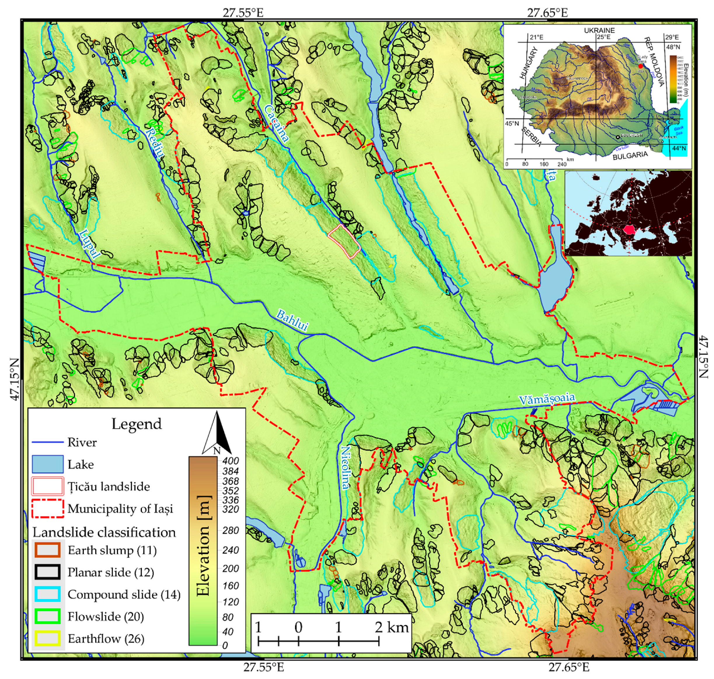
Figure 1. Location of Iași Municipality (Northeastern Romania) and its terrain morphology. The landslide inventory is from [62], and the numbers in parentheses represent the landslide type based on the classification of [63]. (high-resolution image is available at https://doi.org/10.6084/m9.figshare.14915103.v2).
Remotesensing 13 03862 g001
Figure 2. Mean annual rainfall measured at the Iaşi meteorological station (1921-1955 data from [85], and 1961-2018 data from ECA&D [86,87]). The red line indicates the polynomial loess smooth trend with a 0.5 span. At the bottom are represented the landslide events in the Municipality of Iaşi as reported by [77,79]. (high-resolution image available at https://doi.org/10.6084/m9.figshare.14915148.v1).
Remotesensing 13 03862 g002
Figure 3. Țicău landslide location within Iași Municipality. (a) Detailed view of the landslide. Solid red lines are the scarp and toe of landslide, according to [78]. Dashed red lines are the approximate boundaries of the 1942 event, according to the same source. The photos are in Figure 4. (b) Aerial photography of Țicău neighborhood. The solid red line represents the scarp affected by multiple reactivation events in the past. The red dashed line describes the location of the sector investigated in this study. The blue line represents the trace of the geological cross-section over the landslide. (c) The lithological section for the Țicău landslide. The question marks are placed because of the uncertainty between the displaced material and the bedrock. (high-resolution image available at https://doi.org/10.6084/m9.figshare.14915220.v1).
Remotesensing 13 03862 g003
Figure 4. Evidence of surface displacements occurring over the Țicău landslide affected area. (a) Centimeter cracks in the outer wall of a house; (b) wall cracks; (c,d) damage to stabilizing infrastructure; (e) damaged fence; (f) roadway cracks and leaned electric pole (red arrow); (g) wall bulging; (h) tilted trees, red arrows indicate the direction of displacement. (high-resolution image available at https://doi.org/10.6084/m9.figshare.14915250.v1).
Remotesensing 13 03862 g004
Figure 5. Example of connection graph for the interferogram generation: (a) Sentinel-1 ascending dataset with PSI technique, and (b) ERS ascending dataset with the SBAS algorithm. (high-resolution image available at https://doi.org/10.6084/m9.figshare.14915259.v1).
Remotesensing 13 03862 g005
Figure 6. Velocity maps derived by processing the SAR data stacks: (a,b) Sentinel-1 ascending orbit, (c,d) Sentinel-1 descending orbit, and (e,f) ENVISAT ascending orbit. Images on the right are focused on the investigated Țicău landslide. (high-resolution image available at https://doi.org/10.6084/m9.figshare.14915292.v1).
Remotesensing 13 03862 g006
Figure 7. The components of the 3D velocity: (a) along the slope for the ascendent orbit, (b) along the slope for the descendent orbit, (c) vertical, (d) E-W. (high-resolution image available at https://doi.org/10.6084/m9.figshare.16649611.v1).
Remotesensing 13 03862 g007
Figure 8. The official landslide hazard zonation, the landslide velocity hot-spots identified in the present study, and the mapped landslides by [62,79] in Iasi Municipality. (high-resolution image available at https://doi.org/10.6084/m9.figshare.14916003.v2).
Remotesensing 13 03862 g008
Figure 9. Displacement time series trend of representative PS measurements for Țicău landslide and the rainfall time Scheme 0. while for the descending orbit, PSs bigger than 0.2. The trend is derived with the methodology presented in Section 3.2, and the trend lines have 10% transparency. The trend breakpoints are plotted as points rug plots with 10% transparency. (high-resolution image available at https://doi.org/10.6084/m9.figshare.14920113.v1).
Remotesensing 13 03862 g009
Figure 10. The magnitude of the displacement field from the numerical modeling with different parameters values combinations. The red dashed line in the model represents the point from which we artificially enlarged the model to reduce the boundary effect, thus not reflecting the actual topography. (high-resolution image available at https://doi.org/10.6084/m9.figshare.14920119.v2).
Remotesensing 13 03862 g010
Figure 11. History points of displacement magnitude (for the location of the points, see Figure 3). (high-resolution image available at https://doi.org/10.6084/m9.figshare.14920125.v2).
Remotesensing 13 03862 g011
Figure 12. Sliding surface depicted based on the maximum shear strain increments distribution. (high-resolution image available at https://doi.org/10.6084/m9.figshare.14920128.v2).
Remotesensing 13 03862 g012
Figure 13. Influence of the water level in the dynamics and mechanism of the landslide–Contours of displacement magnitude (left) and maximum shear strain increment (right) for the low level of the water table (a,b, respectively) and the high level of the water table (c,d, respectively). (high-resolution image available at https://doi.org/10.6084/m9.figshare.14920137.v2).
Remotesensing 13 03862 g013
Table 1. Specific parameters of SAR image datasets that were used in this study.
SensorParameters
Orbit DirectionTrack No.Time IntervalRepeat Cycle (days)No. of ImagesProduct TypeLocal Incidence AnglePolarizationAzimuth res. (m)Range res. (m)Technique
ERS-1Descending1931992–19963511SAR~22°VV624SBAS
ERS-21931995–20003531SAR~22°VV624
ENVI
SAT
Ascending4292002–20093519ASAR IM~23.5°VV624
Descending1932003–20103520ASAR IM~22°VV624
Sentinel-1 A/BAscending582014–201712, 6 1123Wide Swath~39°VV520PS
Descending1092014–201712, 6 1127Wide Swath~37°VV520
1 12 days repeat cycle until October 2016 when the second satellite was launched, and 6 days afterward.
Table 2. The geotechnical properties that are assigned to the materials in the numerical modeling.
LayerUnit Weight [kN/m3] Friction   Angle   ( ϕ ) Effective Cohesion
c’ [kPa]
Oedometric Module [kPa]Tension
t [kPa]
Young’s Modulus (E) [kPa]Poisson’s Ratio (ν)
1. Clay17.424º259243207886.530.3
2. Silty clay19.225º206590105622.870.3
3. Clay18.724º2516,4341514,504.850.4
4. Silt2027º1012,520510,682.600.3
5. Clay19.524º309522208404.230.4
6. Landslide debris19.718º
20º
22º
25º
2
5
10
15
9000 *0
1
2
3
15,000.00.4
7. Bedrock20.538º10014,00010060,000.00.28
* Mean value based on data from boreholes. Values in bold were assumed or empirically calculated.
Publisher’s Note: MDPI stays neutral with regard to jurisdictional claims in published maps and institutional affiliations.