Article

Soil Salinization Level Monitoring and Classifying by Mixed Chaotic Systems

1
College of Information Engineering, Qujing Normal University, Qujing 655011, China
2
Faculty of Land Resource Engineering, Kunming University of Science and Technology, Kunming 650093, China
3
Department of Mechanical Engineering, National Chung Cheng University, Chiayi 621301, Taiwan
4
Advanced Institute of Manufacturing with High-Tech Innovations, National Chung Cheng University, Chiayi 621301, Taiwan
5
Graduate Institute of Automation Technology, National Taipei University of Technology, Taipei 10608, Taiwan
6
College of Applied Arts and Science, Beijing Union University, Beijing 100083, China
7
College of Resource and Environment Sciences, Xinjiang University, Urumqi 830046, China
*
Author to whom correspondence should be addressed.
Remote Sens. 2021, 13(19), 3819; https://doi.org/10.3390/rs13193819
Submission received: 25 August 2021 / Revised: 14 September 2021 / Accepted: 17 September 2021 / Published: 24 September 2021
(This article belongs to the Section Environmental Remote Sensing)

Abstract

:
Soil salinization process is a complex non-linear dynamic evolution. To classify a system with this type of non-linear characteristic, this study proposed a mixed master/slave chaotic system based on Chua’s circuit and a fractional-order Chen-Lee chaotic system to classify soil salinization level. The subject is the soil in Xinjiang with different levels of human interference. A fractional-order Chen-Lee chaotic system was constructed, and the spectral signal processed by the Chua’s non-linear circuit was substituted into the master/slave chaotic system. The chaotic dynamic errors with different fractional orders were calculated. The comparative analysis showed that 0.1-order has the largest chaotic dynamic error change, which produced two distinct and divergent results. Thus, this study converted the chaotic dynamic errors of fractional 0.1-order into chaotic attractors to build an extension matter-element model. Finally, we compared the soil salt contents (SSC) from the laboratory chemical analysis with the results of the extension theory classification. The comparison showed that the combination of fractional order mixed master/slave chaotic system and extension theory has high classification accuracy for soil salinization level. The results of this system match the result of the chemical analysis. The classification accuracy of the calibration set data was 100%, and the classification accuracy of the validation set data was 90%. This method is the first use of the mixed master/slave chaotic system in this field and can satisfy certain soil salinization monitoring needs as well as promote the application of the chaotic system in soil salinization monitoring.

Graphical Abstract

1. Introduction

Soil is made up of a complex mix of minerals, organic matter, living organisms, moisture, and air [1,2]. One of the global soil problems is soil salinization, especially in arid and semi-arid regions where evaporation is strong, rainfall is scarce, and soil salinization is particularly serious. Soil salinization leads to serious consequences such as soil fertility decline, soil compaction, and reduced crop productivity. Therefore, a timely, fast, and accurate grasp of the soil salinization status is essential to regional ecological stability [3,4,5,6,7,8]. At the same time, the salt content of saline soil is related to multiple components of the soil sample, and there is a complicated nonlinear relationship between the salt content and the hyperspectral reflectance curve. Therefore, it is difficult to reveal the nonlinear dynamic evolution process of soil salinization.
Xinjiang is located in an arid/semi-arid area rich in land and resources that is currently an important agricultural backup resource area for China [9,10,11]. However, the soil salinization in Xinjiang mainly refers to the salt in underground water rising to the soil surface through capillaries. After the water evaporates, the salt accumulates on the soil surface. Saline soil is also called saline-alkaline soil and mainly occurs in soil with high evaporation levels in arid/semi-arid areas and areas with high dissolved salt content in underground water [12,13]. Salinization not only damages resources and causes huge losses in agricultural production [14,15,16] but also threatens the environment and ecology. As a result, salinization has become a global problem [17,18]. Changes in soil salt content (SSC) are affected by the natural environment and human activities. A better soil salinization assessment requires spatial complexity and law of change that sufficiently describe salt content.
Soil salinization development is a complex non-linear dynamic evolutionary process that is closely related to factors such as geology, geomorphology, hydrology, climate, and human activities [19,20]. These dynamic change features and laws have always been popular research topics. Some studies have concentrated on predicting the salt content or nutritional content of saline soils. Farifteh et al. [21] prepared six types of soil with different MgCl2, NaCl, KCl, K2SO4, MgSO4, and Na2SO4 concentrations. The salts are irrigated into three types of soil samples, silty clay loam, sandy loam, and sand texture soil. The relationship between the soil spectrum features and salt content was then analyzed. The result shows that as salt concentration decreases, the number and clarity of the diagnostic absorption waveband also decrease. The spectrum has the highest prediction accuracy towards MgCl2 and MgSO4 but has the lowest prediction accuracy towards KCl and Na2SO4. The absorption feature of wavebands above 1300 nm became wider. Srivastava et al. [22] used visible-near infrared (VNIR) spectrum technology to evaluate the soil salt content of saline soil in the Indo-Gangetic plains (IGP). It found that the area’s soil salt content is sensitive to wavebands in the 1390–2400 nm range. The model proposed in this study can explain 80% or more of the electrical conductivity (EC), Na+, Cl, Mg2+, sodium adsorption ratio (SAR), and Ca2+ changes in the validation set. Wang et al. [23] collected saline soil spectrums in the Yellow River Delta region of China and found that the correlation coefficient between salinity spectral index (SSI) and SSC reached 0.91. Estimation with SSI indicated that the SSC single variable regression model’s coefficient of determination was 0.873, and the root-mean-square deviation was 0.986. Mouazen et al. [24] studied soil samples in Belgium and Northern France and used three types of model building methods to predict phosphorus, sodium, magnesium, and potassium content. The results showed that by using the partial least squares regression’s (PLSR) latent variables as a back-propagation neural network (BPNN), the predictive capability of the BPNN-LV model was the best. The RPD (ratio of the performance to deviation) value for organic carbon (OC(g/kg)) and magnesium was 2.54, and the RPD values for phosphorus, sodium, and potassium were between 1.77 to 1.94. Wang et al. [25] used Xinjiang’s saline soil as their subject and analyzed the relationship between main salt ions and spectrums of fresh, air dried, and dried soil samples. The results show that the smaller the diameter of soil particles, the better the spectrum predictive result towards soil ion content. The inversed ion content of the fitted model built for dried soil was the most precise, and the RPD for K+, Na+, Ca2+, and SO42− reached above 2.
Small changes in soil parameters or the environment can cause differences in spectral reflectance, and such subtle differences are difficult to distinguish. At present, few studies have been conducted on the classification of soil salinization degree, and there is currently no report of chaos theory being used for salinization study. However, chaos theory has pseudo-randomness, ergodicity, regularity, and sensitivity towards initial conditions; thus, it is often applied to non-linear systems [26,27,28,29,30]. This paper is the first to use mixed chaos theory to describe the spectrum dynamic change law of soil with different salt content. The objective is to explore the feasibility of using chaos in the spectrum field. In this study, we analyzed saline soil from areas with different levels of human interference in Fukang City (Xinjiang) with a mixed fractional-order master/slave chaotic system (combination of Chua’s chaotic circuit and fractional order Chen-Lee master/slave chaotic system). We used chaotic dynamic error, chaotic attractor, and extension theory to classify spectrum data from the soil with different salinization levels, which allowed us to determine the study area’s soil salinization level. This research is divided into five sections, the first content is the Introduction, the second is Materials and Methods, the third is Simulation results, the fourth is Discussion, and the fifth is Conclusions. The aims of this research are: (1) Explain the feasibility of the application for the Chen-lee chaotic system in the field of soil hyperspectral sensing. (2) Propose a new intelligent classification system architecture to classify the degree of soil salinization. (3) Provide a scientific basis for soil salinization management in the study area, as well as provide a time and labor-saving soil salinization data extraction method.

2. Materials and Methods

2.1. Soil Sample Collection

There is a severe soil salinization problem in the agricultural development of Xinjiang. The total saline-alkaline soil area is approximately 8.476 million hm2, including cultivated land. Overall, 31.1% of the area is jeopardized by saline-alkaline conditions, making it the largest saline-alkaline soil area in China. Salinization and development have long been important factors that limit sustainable development of agriculture, resources, environment, and social economics in Xinjiang. The soil samples used in this study were collected in the desert area of Fukang in May 2017. The Fukang desert area is located in Fukang City, Xinjiang Provence, its geographic coordinates are 87°44′–88°46′E, 43°29′–45°45′N, which is a typical temperate continental desert climate [31], where the winter is cold, summer is hot, sunlight is sufficient, annual average temperature is 6.6 °C, annual and daily temperature differences are large, precipitation is sparse, annual average precipitation is 145 mm, evaporation is strong, and the average annual evaporation potential is 2292 mm. The soil types include gray desert soil, cracked soil, and sandy soil. The soil texture in this area is sandy soil, and the soil salinization is serious, which is represented in the arid area of northwestern China.
In order to arrange the sampling points reasonably, it is necessary to conduct a field investigation to determine the scope of the research area; in this paper, the research is divided into Areas A and B. Area A is an area without human activities, which is far away from human settlements, and the soil basically maintains the original ecological features. Area B is an area affected by human activities, which is located near Xinjiang’s 102 Production and Construction Army Corp and has had heavier human activity in recent years. Most of the land has been developed into elm forests and growing areas.
Five sampling lines were laid out in Area A, with the spacing of the sampling lines is about 500 to 700 m, and five representative sampling points were set on each sampling line. Six sampling lines were arranged in Area B. The interval between the sampling lines was about 400 to 600 m, and five representative sampling points were set on each sampling line. The soil is mainly collected from the top 0–10 cm of soil, 25 sampling points are taken from Area A, and 30 sampling points are taken from Area B. Approximately 1 kg of soil was taken from each sampling point. In this way, a grid that can cover different areas is formed in the entire study area. The sampling points can not only better reflect the soil properties of each area but can also better control the uniformity of the sampling points in each area.
The samples were taken back to the laboratory and air-dried naturally. Pebbles, animal, and vegetation remains were removed. The remaining soil was grounded, put through a 1 mm sieve, and sent to Xinjiang Institute of Ecology and Geography. Chemical analysis was used to determine the SSC; the salt content of the soil sample was measured in the soil clear liquid using the Multi 3420 SET B portable multi-parameter analyzer, and the salt content was converted from the salinity data measured by this instrument. The location of the study area and the soil sampling points are shown in Figure 1.

2.2. Soil Hyperspectral Measurement

The field hyperspectral of the soil samples was measured by FieldSpec® 3Hi-Res spectrometer, manufactured by an ASD (Analytical spectral device) company, which is affiliated to PANalytical, the Netherlands. The measurement range of all bands was 350–2500 nm, and the number of output bands was 2151. The wavelength range of 350–1000 nm is in the visible light with a spectral resolution of 3 nm, and the sampling interval is 1.4 nm. The range of 1001–2500 nm is near-infrared with a spectral resolution of 8 nm and a sampling interval of 1.1 nm. The re-sampling interval was 1 nm. The spectrometer is widely used in remote sensing, geology, agriculture, environment, surveying, mapping, and other fields. The measurement objects can be soil, ice and snow, cultural relics, minerals, plants, rocks, metals, and so on. The relevant technical parameters are shown in Table 1.
The requirement for field spectrum measurement is a clear day with no cloud and wind. The probe is placed 15 cm vertically above the soil sample to collect the spectrum. Before each measurement, a white board is used for calibration to remove dark current effects. To make the spectrum data representative, five locations near each sampling point were used to collect the spectrums. Each location was measured 10 times to obtain 50 spectrum reflectance curves. The curves are averaged to obtain the final sample spectrum reflectance data.

2.3. Spectrum Data Pre-Processing

Because the spectrometer itself has a margin of error and there is noise in the measuring environment, the spectral reflectance can experience baseline drift and multiple scattering effects. These factors can affect the reliability of the final model. Thus, before building the model, it is necessary to pre-process the spectrum data. First, the Savitzky-Golay smoothing is used to treat the spectrum and remove errors that may be caused by spectrum curve noise. However, the 350–399 nm and 2401–2500 nm waveband has a lower spectrum. Thus, the spectral reflectance data we chose to use in this study is the 400–2400 nm wave band with higher signal noise and does not include the wavebands on the two ends. Because of the effects from the moisture absorption belt, the 1400 nm, 1800 nm, and 2200 nm spectrum reflectance curves show clear fluctuation. Therefore, the wavebands near the moisture absorption belt, 1355–1410 nm, and 1820–1942 nm were also removed.

2.4. Classification of Soil Salinization Level

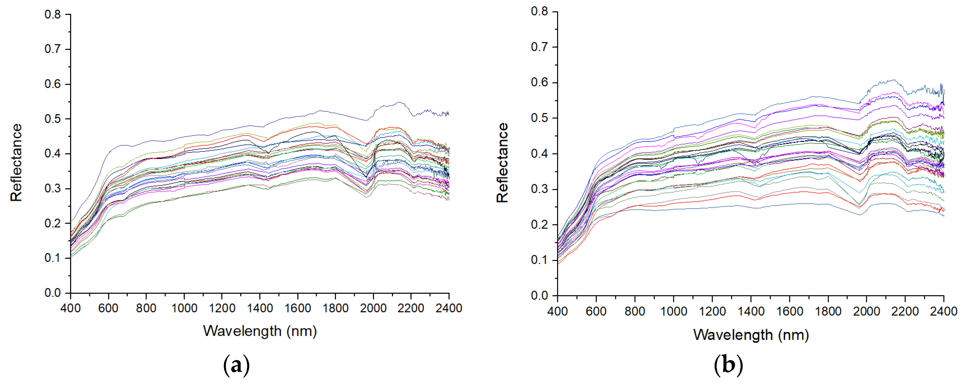
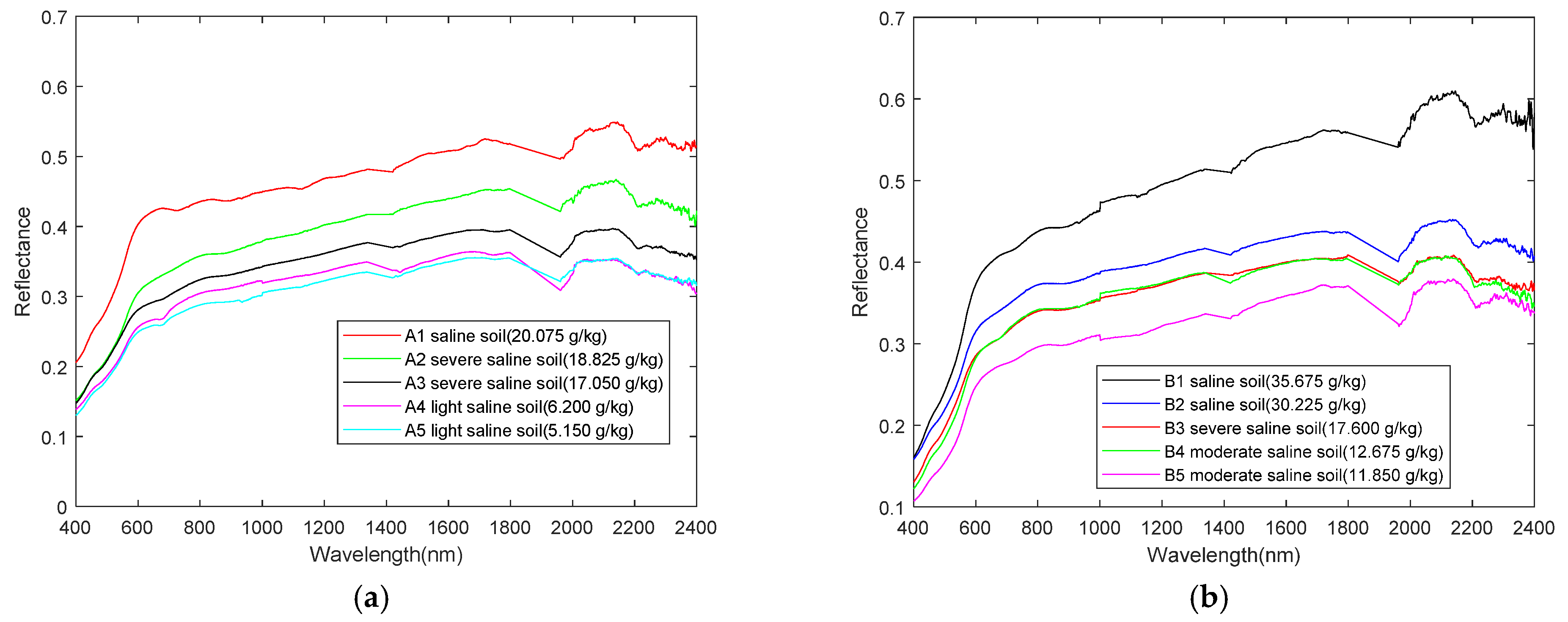
Figure 2 shows the spectral reflectance curves collected in Area A and B sampling points. Near the 1430, 1950, and 2180 nm bands, there is a deeper absorption valley, and at the 700, 900, 1100, 1750, and 2300 nm, there is a shallower absorption valley. As the sampling points change, the 600–1700 nm and 2200–2400 nm spectrum reflectance curves have a higher soil spectrum curve overlap, which makes it difficult to directly identify the objective. Thus, the soil salinization level is divided into five major categories based on the soil salinization level determination standards [32], as shown in Table 2. This study screened the spectral reflectance of sampling points with different salinization levels in Area A and B, as shown in Figure 3. Figure 3 shows that the change in spectral reflectance curve for different salinization levels is basically consistent. However, differences in soil salt content cause changes in spectrum reflectance. As the soil salt content increases, the spectrum reflectance also increases. This phenomenon is consistent with the result of previous studies [33].

2.5. Chua’s Circuit

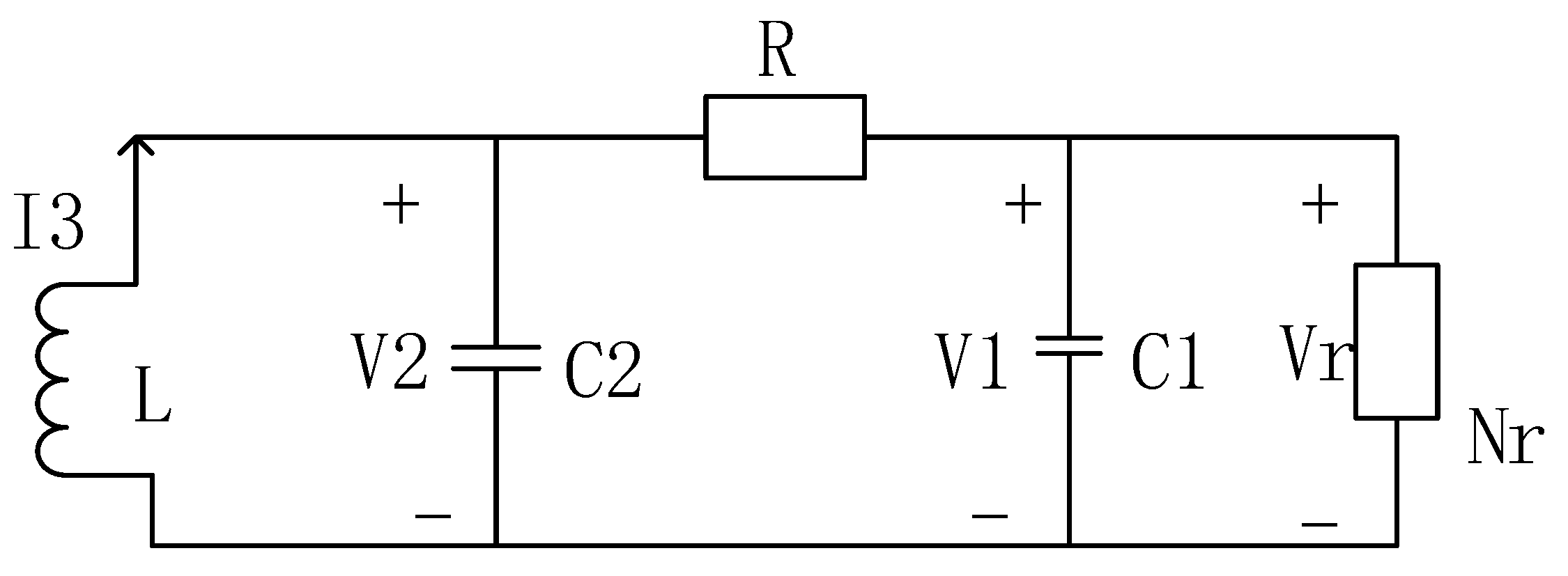
Chua’s circuit is a type of simple non-linear electronic circuit design [34,35], as shown in Figure 4. It is formed by four linear components, the inductor L, resistor R, capacitor C 1 , C 2 , and non-linear Chua’s diode N r .
According to Kirchhoff’s Law, Chua’s circuit status equation is shown as Equation (1).
{ d V C 1 d t = 1 C 1 [ 1 R ( V 2 V 1 ) f ( V 1 ) ] d V c 2 d t = 1 C 1 [ 1 R ( V 1 V 2 ) + I 3 ] d I 3 d t = 1 L V 2 }
where, V 1 , V 2 , and I 3 are the voltage on the two ends of the capacitor and the current that passes the inductor, respectively; f ( V 1 ) is the non-linear resistor; N r is the non-linear Chua’s diode.
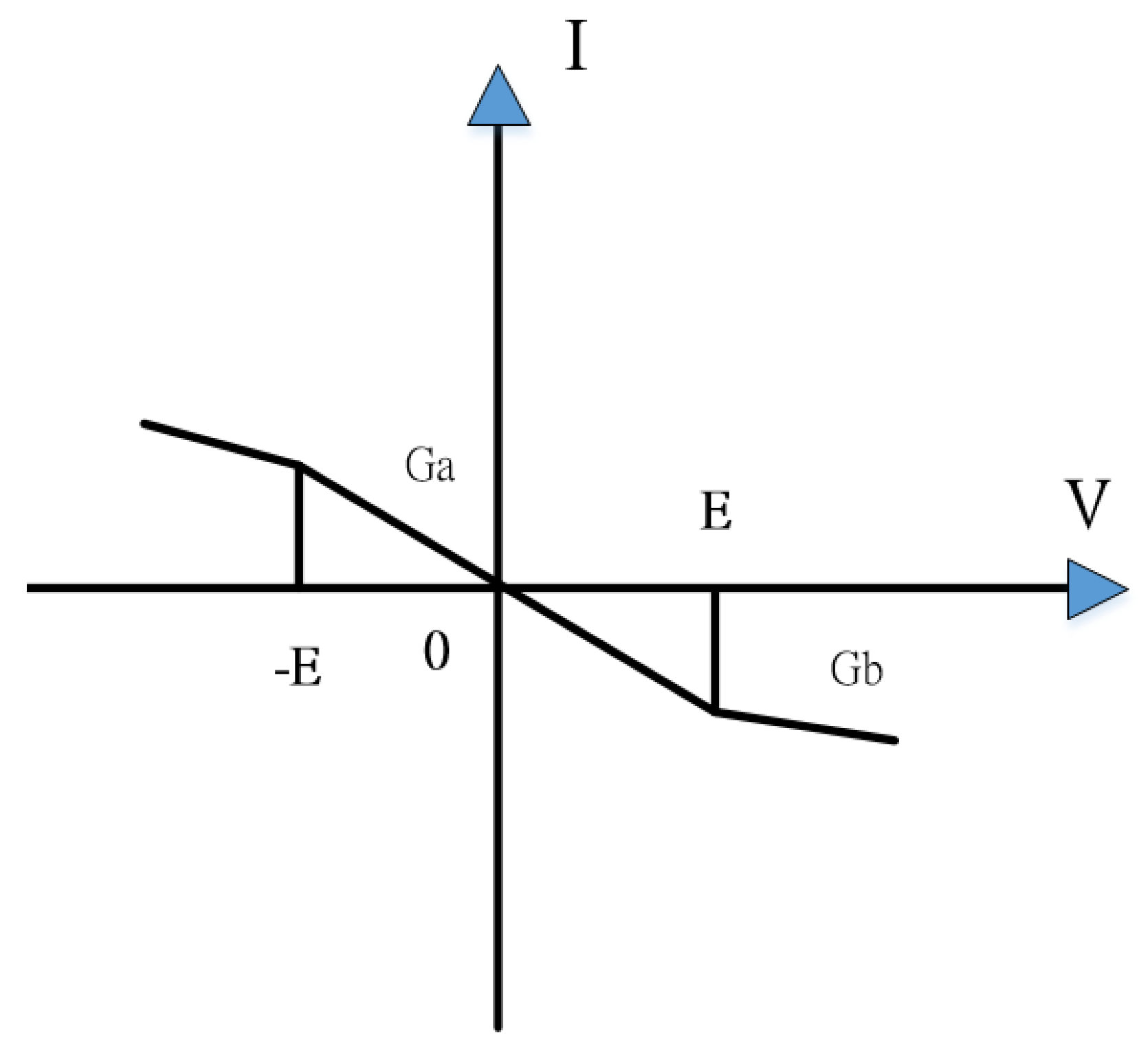
The characteristic curve of the non-linear Chua’s diode N r is as shown in Figure 5.
The polynomial reported in Figure 2 is, as shown in Equation (2):
f ( V 1 ) = G b V 1 + 1 2 ( G a G b ) [ | V 1 + E | | V 1 E | ]
where, G a and G b are the slopes of the inside and outside line turn segment, E is the turning point voltage, I is current, and V is voltage.

2.6. Chen-Lee Chaotic System

Chaos theory is a type of non-linear system theory. Every chaotic system has chaotic attractors, and the signal outputted by the attractors displays an orderly but non-periodic motion trajectory. Every tiny change inputted can significantly affect the outputted motion track and chaotic attractor pattern. This is the butterfly effect. The chaotic self-synchronization system is composed of the master system (MS) and slave system (SS) and can be separately expressed as Equations (3) and (4).
X ˙ = A X + f ( X )  
Y ˙ = A Y + f ( Y ) + U    
where, X R N and Y R N are the state vectors, X represents the master system states, Y represents slave system states. A is an N × M matrix, f(X) and f(Y) are non-linear vectors, and U is the designed non-linear control component. By making the master/slave mutually pursue each other and produce dynamic errors, we can determine system feature changes. When the master/slave receives a signal, subtraction of the master/slave can obtain the dynamic error status.
This study uses a fractional-order master/slave Chen-Lee chaotic system [36,37,38,39], and its dynamic equation can be expressed as Equation (5):
{ x ˙ = y z + α x y ˙ = x z + β y z ˙ = ( 1 / 3 ) x y + γ z
where, α , β , and γ are the system parameters. When they are 5, −10, and −3.8, the system is guaranteed to have a chaotic attractor [40]. x, y, and z represent state variables of the Chen-Lee chaotic system.
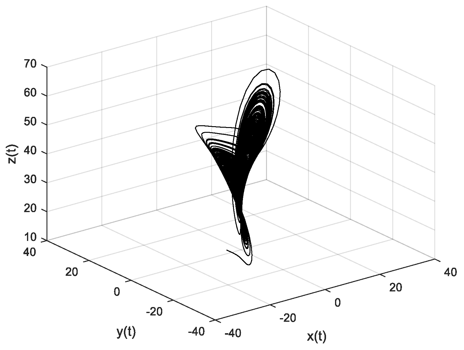
The Chen-Lee chaotic system track is as shown in Figure 6.
According to the master/slave chaotic dynamic error produced by the Chen-Lee chaotic system, if X = [ x 1 , x 2 , x 3 ] T , Y = [ y 1 , y 2 , y 3 ] T , U = [ u 1 , u 2 , u 3 ] T , T denotes the transpose of a matrix, then X is the MS, and Y is the SS. Equations (3) and (4) can be revised as Equations (6) and (7).
X ˙ = A X + f ( X ) = [ α x 3 0 x 3 β 0 1 3 x 2 0 γ ] [ x 1 x 2 x 3 ]
Y ˙ = A Y + f ( Y ) + U = [ α y 3 0 y 3 β 0 1 3 y 2 0 γ ] [ y 1 y 2 y 3 ] + U
To make the master/slave pursue each other and produce dynamic errors, which we can use to determine system feature changes, we defined the errors e 1 = x 1 y 1 , e 2 = x 2 y 2 , e 3 = x 3 y 3 . Thus, the dynamic error can be expressed as Equation (8).
{ e 1 ˙ = ( α e 1 e 2 e 3 ) + ( y 2 e 3 y 3 e 2 ) u 1   e 2 ˙ = ( β e 2 + e 1 e 3 ) + ( y 1 e 3 + y 3 e 1 ) u 2   e 3 ˙ = ( γ e 3 + 1 3 e 1 e 2 ) + 1 3 ( y 1 e 2 + y 2 e 1 ) u 3
In order to guarantee that the error dynamics also demonstrate a chaotic behavior, we set the control component U = [ u 1 , u 2 , u 3 ] T as Equation (9), and the controlled error dynamic equation is shown in Equation (10).
{ u 1 = y 2 e 3 y 3 e 2   u 2 = y 1 e 3 + y 3 e 1   u 3 = 1 3 ( y 1 e 2 + y 2 e 1 )
{ e 1 ˙ = ( α e 1 e 2 e 3 )   e 2 ˙ = ( β e 2 + e 1 e 3 )   e 3 ˙ = ( γ e 3 + 1 3 e 1 e 2 )
It shows that the dynamic error Equation (10) has the same structure as Equation (5). Therefore, we can guarantee the dynamic error Equation (10) will also show a stranger attractor with the same system parameter. We can reform Equation (10) to a matrix form as in Equation (11).
[ e ˙ 1 e ˙ 2 e ˙ 3 ] = [ α e 3 0 e 3 β 0 1 3 e 2 0 γ ] [ e 1 e 2 e 3 ]
After organizing to let its parameter satisfy α > 0   , β < 0   ,   0 < α < ( β + γ ) , we obtain Equation (12).
[ e ˙ 1 e ˙ 2 e ˙ 3 ] = [ α 0 0 0 β 0 0 0 γ ] [ e 1 e 2 e 3 ] + [ e 3 e 2 e 3 e 1 1 3 e 2 e 1 ]
To make the dynamic error produced by the Chen-Lee chaotic system be clearer and conform more to non-linearity, this study used the fractional order differential theory proposed by Grünwald-Letnikov [41,42]. Its relative dynamic error e can be expressed as Equation (13).
D e ± α e m Γ ( m + 1 ) Γ ( m + 1 ± α ) e m α
To be able to clearly express spectrum signal features, Equation (13) is re-written as Equation (14).
d α d t α [ e ˙ 1 e ˙ 2 e ˙ 3 ] [ α 0 0 0 β 0 0 0 γ ] d α d t α [ e 1 1 e 2 1 e 3 1 ] + d α d t α [ e 3 e 2 e 1 0 e 3 e 1 e 2 0 1 3 e 2 e 1 e 3 0 ]
After the fractional order differential theory’s Equation (14) differential is calculated, we obtained Equation (15)
[ D q e 1 D q e 2 D q e 3 ] = [ α 0 0 0 β 0 0 0 γ ] [ e 1 1 + ρ e 2 1 + ρ e 3 1 + ρ ] + [ Γ ( 1 ) e 2 e 3 e 1 ρ Γ ( 1 + ρ ) Γ ( 1 ) e 1 e 3 e 2 ρ Γ ( 1 + ρ ) Γ ( 1 ) e 1 e 2 e 3 ρ 3 Γ ( 1 + ρ ) ]
where q = ( 1 ρ ) is used to satisfy 0 < q < 1 . Γ(x) is the Gamma function, and its parameters α , β , γ are non-zero constants, which can be separately expressed as Equations (16)–(18).
α = α Γ ( 2 ) Γ ( 2 + ρ ) > 0
β = β Γ ( 2 ) Γ ( 2 + ρ ) < 0
γ = γ Γ ( 2 ) Γ ( 2 + ρ ) < 0
To realize the dynamic errors with a digital system, its dynamic errors can be set as e 1 [ i ] = x 1 [ i ] y 1 [ i ] , e 2 [ i ] = x 2 [ i ] y 2 [ i ] , e 3 [ i ] = x 3 [ i ] y 3 [ i ] . In view of this, the dynamic self-synchronization error system mapping can be revised as in Equation (19), below:
[ φ 1 [ i ] φ 2 [ i ] φ 3 [ i ] ] [ α 0 0 0 β 0 0 0 γ ] [ e 1 [ i ] 1 + ρ e 2 [ i ] 1 + ρ e 3 [ i ] 1 + ρ ] + [ Γ ( 1 ) e 2 [ i ] e 3 [ i ] e 1 [ i ] ρ Γ ( 1 + ρ ) Γ ( 1 ) e 1 [ i ] e 3 [ i ] e 2 [ i ] ρ Γ ( 1 + ρ ) Γ ( 1 ) e 1 [ i ] e 2 [ i ] e 3 [ i ] ρ 3 Γ ( 1 + ρ ) ]
In this study, we will use the Self-Synchronization Error System Mapping to extract the feature differences in spectral reflectance of soil salinization level.

2.7. Extension Theory

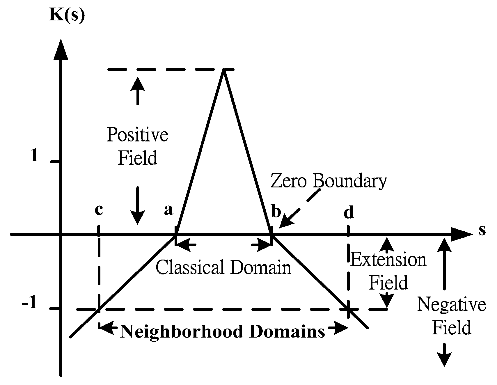
Extension theory studies the possibility of extending events and pioneer innovative laws and methods; it is also used to solve contradictions [43,44]. Extension theory can be divided into two parts, the first part is the matter-element theory, and the second part is the extension set. Matter-element theory mainly studies the extendibility of matter-element and the nature of matter-element transformations. The extension set quantifies during the contradiction solving process. Finally, we build a corresponding quantifying tool and plan according to the correlation level. The fuzzy set range is extended from <0, 1> to <−∞, ∞>. The extension set is as shown in Figure 7.
Extension theory uses the matter-element model to describe an event. The extension theory builds a matter-element model for specific items/events. The matter-element model can be expressed as Equation (20).
R = ( N , c , v )
where R represents an event, N is the name of the event, c is the characteristic of the event, and v is the event measurement.
The equation of extension theory can be seen in a previous study [45].

2.8. Intelligent Classification System Architecture

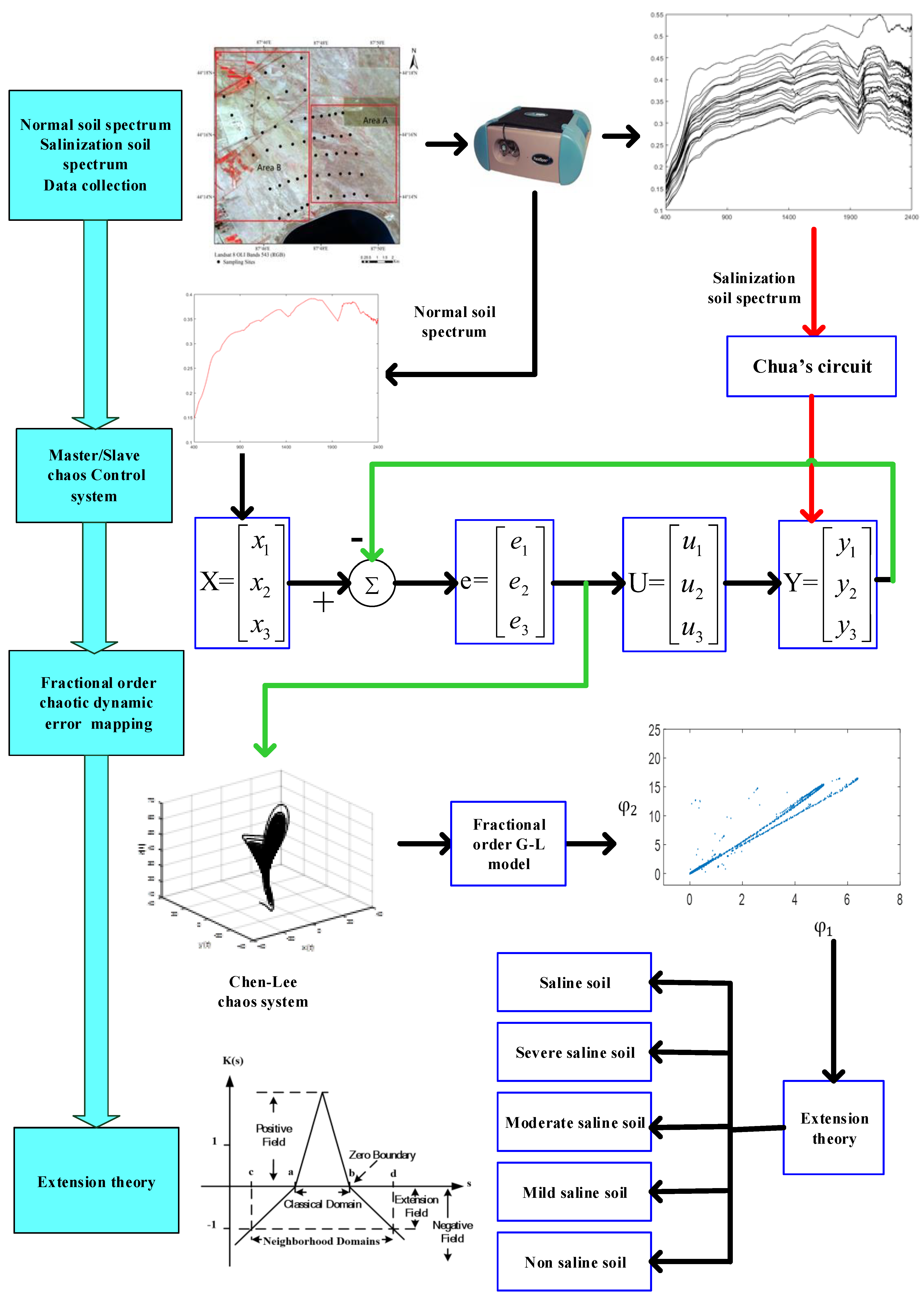
The spectrum of saline soil is an extremely complex evolution process, which is affected by many inter-influencing factors, and the process exhibits strong nonlinear characteristics. Small changes in soil parameters or the environment will cause differences in spectral reflectance, making such subtle spectral differences difficult to identify. The Chen-Lee chaotic system is used as a signal analysis tool. The intelligent classification system architecture can be shown in Figure 8. The specific eight steps can be described as follows:
One, we use an ASD spectrometer to collect the spectral signal of the soil in the study area and observe the hyperspectral signal of the non-saline soil, which is used as a part of the input signal of the X variable.
Two, the hyperspectral signal of the saline soil is decomposed by Chua’s circuit, and the Chua’s circuit status equation is shown as Equation (1). The spectral sequence processed by Chua’s circuit is used as a part of the input signal of the Y variable.
Three, it generates the main system signal and the slave system signal with the self-synchronization of the chaotic system. The hyperspectral signal is substituted into the master-slave chaotic system, and the slave system can be synchronized with the master system under nonlinear control; the chaotic self-synchronization system can be separately expressed as Equation (3) and (4).
Four, the hyperspectral signal and salinity information of the saline soil are substituted into the constructed fractional-order Chen-Lee chaotic system, further subtraction is performed, and the dynamic equation of fractional order master/slave Chen-Lee chaotic system can be expressed as Equation (5).
Five, we further obtained the dynamic error of the master-servant chaotic system, and the dynamic self-synchronization error system mapping can be revised as in Equation (19). Spectrum signals from the soil with different salinization levels are introduced into different fractional-order mixed master/slave chaotic systems to produce chaotic dynamic error distribution.
Six, the hyperspectral signal and salinity information of the saline soil are substituted into the constructed fractional-order chaotic system, its dynamic behavior characteristics are analyzed, and the chaotic dynamic error and attractor difference of different sampling points under different fractional orders are discussed.
Seven, the fractional-order chaotic system with the largest dynamic error is extracted, and the extension matter-element model is established based on its chaotic attractor features. The extension theory is used to intelligently classify the system. The matter-element model can be expressed as Equation (20).
Eight, we can draw a phase-plane distribution map based on the state phasors to achieve the purpose of classifying salinization.

3. Simulation results

3.1. Mixed Fractional Order Master/Slave Chaotic System Dynamic Error Distribution

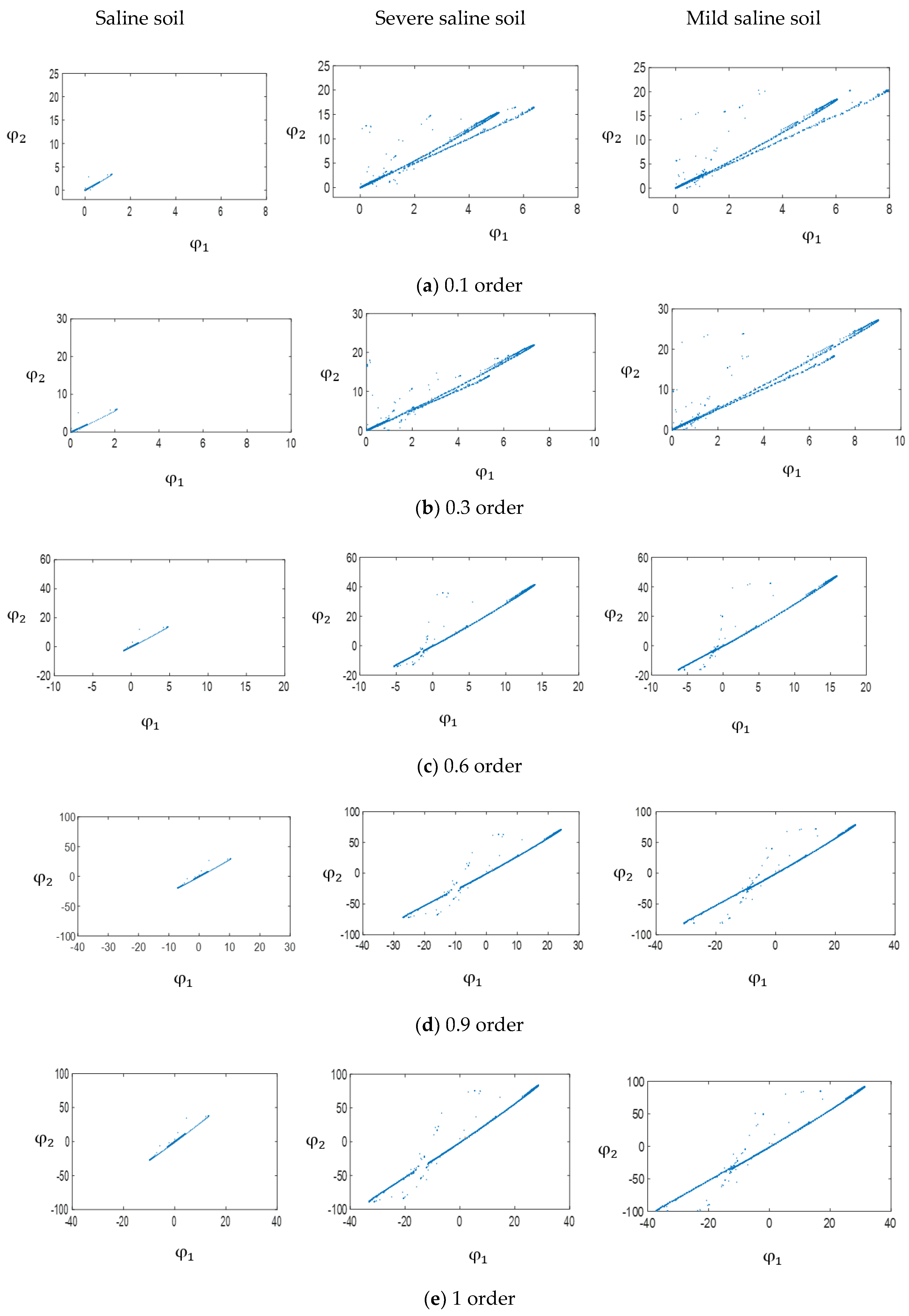
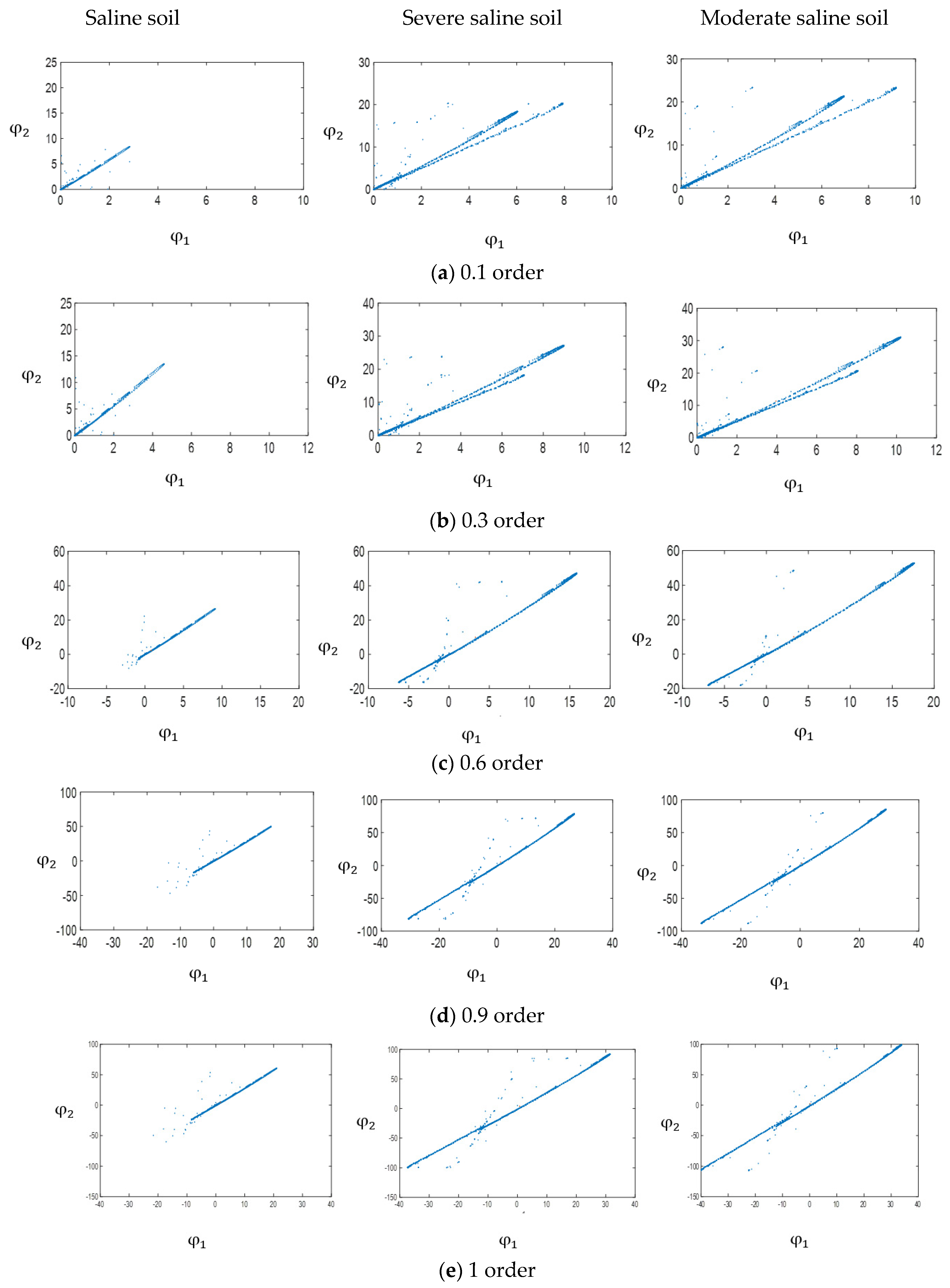
This study combined the Chua’s circuit with the fractional order Chen-Lee master/slave chaotic system to analyze saline soil, severe saline soil, moderate saline soil, mild saline soil, and non-saline soil. Distribution change trend in a different order number is used to search for status change features. Each fractional-order difference is compared, and order numbers with greater dynamic error changes were chosen. Saline soil, severe saline soil, and mild saline soil were chosen for Area A. The chaotic dynamic error distributions for non-integer orders 0.1, 0.3, 0.6, 0.9, and integer-order 1 are shown in Figure 9. Saline soil, severe saline soil, and moderate saline soil were chosen for Area B. The chaotic dynamic error distribution for non-integer orders 0.1, 0.3, 0.6, 0.9, and integer-order 1 are shown in Figure 10. Figure 9 and Figure 10 show that the chaotic dynamic error distribution change trend of the integer and non-integer orders generally form a line. Soil samples with lower salinization had greater X- and Y-axis component changes in chaotic dynamic error distributions and vice versa. Observations also show that of all the fractional orders, the chaotic dynamic error of orders 0.1 and 0.3 shows two divergent lines. However, the change in order 0.1 is more obvious, so we chose non-integer order 0.1 for follow-up analysis.

3.2. Mixed Fractional Order Master/Slave Chaotic Attractor

To make the building of an extension matter-element model easier, this study used the extension theory as a smart classification tool. The chaotic dynamic error distribution is converted to the chaotic attractor pattern for easier extension matter-element model building. Simulations in Section 3.1 show that the dynamic error change in the non-integer order 0.1 mixed fractional-order chaotic system is larger. Thus, we chose the chaotic attractor produced by order 0.1 mixed fractional-order chaotic system for analysis. The chaotic attractor distribution for five sampling points in Area A and B is shown in Figure 11.
Figure 11 shows that the chaotic attractor coordinate distribution exhibits a linear trend because of the different salt contents. The bottom left corners of Areas A and B have sampling points with the highest salt content. The top right corners have sampling points with the lowest salt content. The salt content going from the bottom left to the top right corner exhibits a decrement status. By using this chaotic attractor coordinate distribution map, we can easily identify soil with different salinization levels.

3.3. Building an Extension Matter-Element Model and Extension Classic Domain

To build a smart classification system, this study used the extension theory as the backend classification system. Chaotic attractors are introduced into the extension theory. After building a matter-element model, this study established the extension classic domain range and calculated the correlation level to determine the accuracy of salinization level classification.
Based on the order 0.1 chaotic attractor coordinates shown in Figure 11, the matter-element model vectors from Area A and B are expressed as Equations (21) and (22).
[ s a l i n e s o i l s c 1 [ 0.060561 , 0.170552 ] c 2 [ 0.070561 , 0.180552 ] ] [ s e v e r e s o i l s c 1 [ 2.848537 , 8.187878 ] c 2 [ 3.061576 , 8.789999 ] ] [ l i g h t s o i l s c 1 [ 3.395429 , 9.739077 ] c 2 [ 3.600449 , 10.33127 ] ]
[ s a l i n e s o i l s c 1 [ 0.431058 , 1.2418 c 2 [ 0.855306 , 2.7416 ] ] [ s e v e r e s o i l s c 1 [ 3.603826 , 10.34131 ] c 2 [ 3.613826 , 10.35131 ] ] [ m o d e r a t e s o i l s c 1 [ 3.742886 , 10.73124 c 2 [ 3.95409 , 11.338 ] ]
After building the matter-element model, the extension classic domain and section domain can be established based on the model. The interval range defined by the extension classic domain and section domain is used as the basis for determining soil salinization. The extension classic domain range is shown in Figure 12. The yellow area in Figure 12 is the saline soil classic domain, the orange area is the severe saline soil classic domain, the green area is the moderate salinization classic domain, the red area is the mild saline soil classic domain, and the blue is the section domain of all the saline soil.

3.4. Calculating Correlation Level

After the classic domain is established, we can calculate the correlation level. Table 3 and Table 4 show the soil sample extension correlation levels for Areas A and B. Extension correlation calculation results in Table 3 and Table 4 show that A1, B1, and B2 is saline soil, A2, A3, and B3 are severe saline soil, B4 and B5 are moderate saline soil, and A4 and A5 are mild saline soil. If the correlation level is 1, it is the indicated status; if the reverse, then it is not the indicated status.

3.5. Extension Classification Results

To verify the accuracy of the extension theory classification, we compared the laboratory chemical analysis results to the computer-calculated extension correlation level results. Results for Areas A and B are shown in Table 5 and Table 6, respectively. Simulations show that the extension correlation classification results are consistent with the laboratory chemical analysis results; the classification accuracy of calibration set data is 100%. This study used a combination of Chua’s chaotic circuit and a fractional-order Chen-Lee master/slave chaotic system to analyze soil sample spectrums. The extension theory is used to make classification smarter. The results obtained in this study matched the soil salinization standard proposed by Qifei Li [42]. This shows that the chaotic system can be applied to spectrum analysis. The mixed chaotic system matched with the extension theory proposed in this study can rapidly and intuitively identify soil salinization levels.

3.6. Classification Result of Validation Set

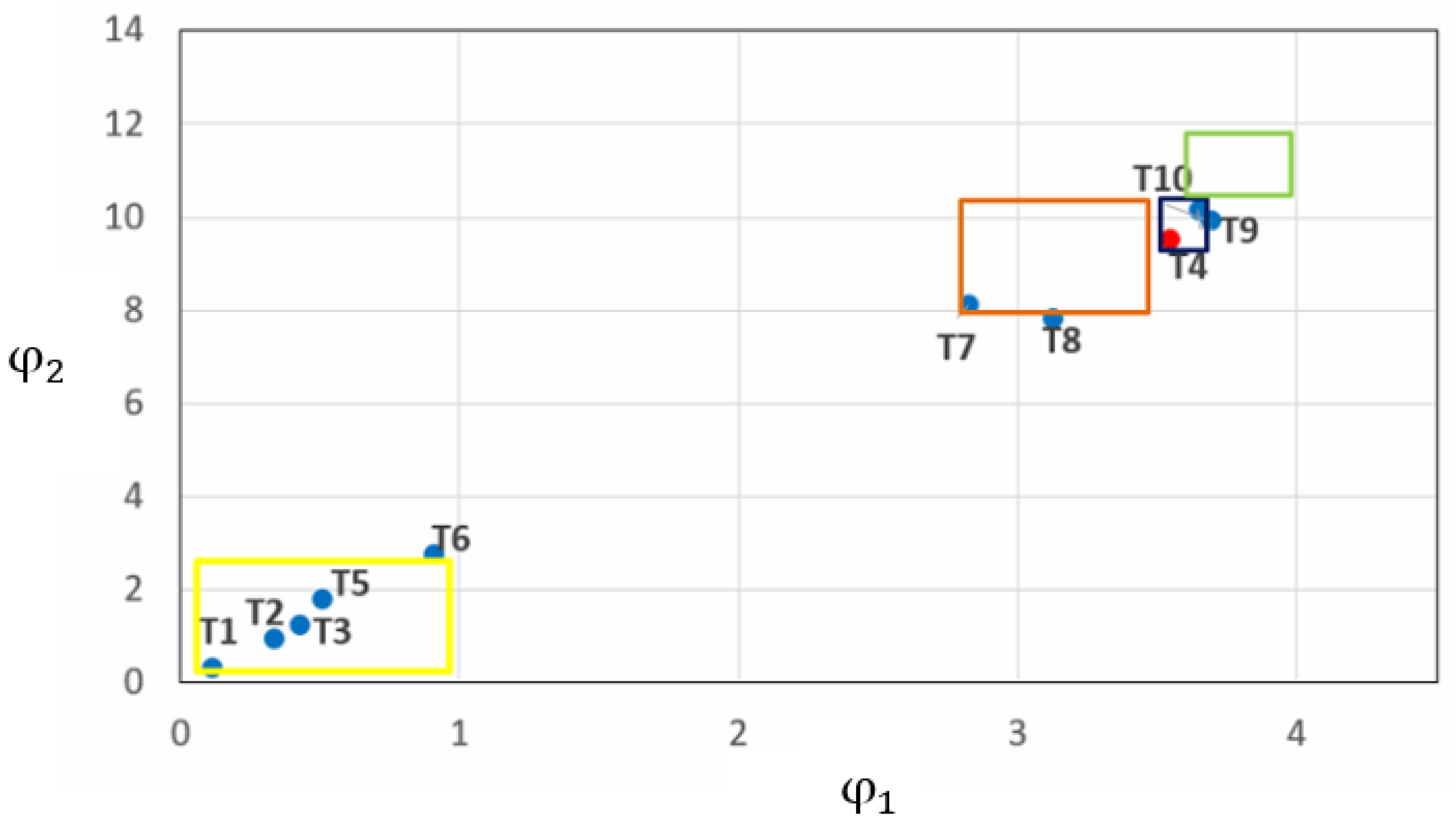
In order to verify the robustness of the system, this paper randomly selected 10 samples from the research areas as the validation set data, substituted the spectral reflectance data into the master/slave chaotic system, and extracted the chaotic attractor into the extension classification system established in this paper. The extension classic domain range of the validation set is shown in Figure 13. The yellow area in Figure 13 is the saline soil extension classic domain; the orange area is the severe saline soil extension classic domain; the blue area is the moderate salinization extension classic domain; the green area is the mild saline soil extension classic domain.
The extension correlation degree value and salt content value of 10 soil samples are shown in Table 7. In Table 7, the correlation degree value is one as the corresponding state. It can be noted that the correlation degrees of T6, T8, T9, and T10 are 0.985, 0.973, 0.987, and 0.964, respectively. Thus, indicating that the attractor phase coordinates of the four samples do not fall within the classical domain. However, the extension distance is very close to the classical domain of soil. This article can consider these four samples as the saline soil state. The attractor phase coordinates of sample T4 fall within the classical domain of moderate saline, but the actual salt content is 20.4 g/kg, which belongs to the saline soil state, so the sample T4 is a misclassified chaotic attractor.
According to the above validation results, the system randomly extracts the spectral reflectance of 10 soil samples for chaotic analysis and extension classification, and the classification accuracy is 90%, which proves that the system is very robust. In the future, the state phasor of the master/servant chaotic dynamic error can be extracted in the way of machine learning for learning classification, or the convolutional neural network can be used to directly identify the coordinate map of the master/servant chaotic dynamic error to achieve a more accurate and robust classification.

4. Discussion

Some scholars use Chen-Lee chaotic systems to study wind power systems. Ying-Che Kuo et al. [46] used the Chen-Lee chaotic system to load the normal and fault signals of the bearings into the chaos synchronization error dynamics system. Results showed that the proposed chaos synchronization method could separate the characteristics completely, which had a better fault diagnosis rate than the methods. Chih-Jer Lin et al. adopted [47] the Chen-Lee chaotic system for analysis and took its chaotic attractor as the feature of the ball bearing malfunction recognition, the method combing Chen-Lee chaotic system, and BPNN (Back Propagation Neural Network) had a high identification rate and overall efficiency for the ball bearing malfunction. Ying-Che Kuo et al. used [48] the unified chaotic system-based design to study the wind turbine blade fault diagnostic system, Lorenz system, the Lu system, and the Chen system was used to identify which one responds best to this system. The experimental results showed that the unified chaotic system had a significant effect on the vibration signal analysis. However, all the researchers did not use a fractional-order Chen-Lee chaotic system. At the same time, there have not yet been reports on the Chen-Lee chaotic system in the field of soil hyperspectral. However, in our paper, we proposed a new method of classifying the degree of soil salinization to achieve a higher-precision classification using the fractional Chen-Lee chaotic system and coupled it with Chua’s circuit and control theory.
Fractional chaotic systems can not only accurately describe the physical model of the system due to the use of fractional orders but also accurately distinguish small differences in signals due to their high sensitivity to initial values. In this paper, the fractional-order chaos system is used to improve the resolution between the peaks of hyperspectral signals, and the effect of the fractional-order chaos system to improve the pretreatment of soil hyperspectral signals is discussed, which provides a new idea for the pretreatment of hyperspectral soil data. Based on the spectrum and salt content information of different sampling points, this paper analyzes the mathematical model and dynamic behavior characteristics of the fractional chaotic system and compares the corresponding chaotic motion trajectories under different fractional orders and identifies the characteristics of the hyperspectral signal. Thereby, the resolution between the peaks of the hyperspectral signal is enhanced, and the best fractional chaotic system is found.
Typical fractional-order chaotic systems include Chen, Lorenz, Sprott, etc. The dynamic behavior characteristics of different combination systems varies. This research proposes a mixed master/slave chaotic system based on the Chua’s circuit and fractional order Chen-Lee chaotic system for classifying saline soil salinization level. It is found that the 0.1-order chaotic dynamic error change is the most obvious, and the fractional order was further analyzed. Based on the characteristics of the 0.1-order chaotic attractor, an extension matter-element model was established, the correlation degree was calculated, and the calculated extension classification result was compared with the salt content data, and the accuracy rate was high. The simulation results show that the method proposed in this research can accurately classify the degree of salinization. However, the classification of saline soil based on other combinations of chaotic systems requires further research and discussion.

5. Conclusions

This study proposes a soil spectrum data analysis method based on fractional order mixed master/slave chaotic system. This is the first time this new method is used to analyze large amount of spectrum data. Soil salinization is a very complex dynamic evolution process that exhibits a very strong non-linear characteristic. Chaos theory can completely and accurately describe this type of very complex non-linear process. The salinization classification method proposed by this study is simple, fast, and highly expandability. In the future, this research method can combine UAV (Unmanned Aerial Vehicle/Drones) hyperspectral images and hyperspectral satellite remote sensing images to further analyze the classification accuracy of soil salinization in a large area. We can extract the fractional-order with the largest dynamic error to improve the classification accuracy by analyzing the chaotic attractor characteristics of the soil hyperspectral at different fractional orders. The results of this paper can be transplanted to embedded devices and used to develop intelligent system processing software for predicting soil elements, so that the entire set of smart classification systems can be portable and faster. It can integrate hyperspectral data collection, storage, analysis, modeling, and other modules, and automatically realize the feature extraction and model prediction of hyperspectral data in batches. This has important application prospects for the development of resource and environmental remote sensing, and creates certain economic benefits.

Author Contributions

A.T. and H.-T.Y. designed the research. A.T. and H.X. performed the experiments. X.-Y.S. and C.F. participated in the data analyses. A.T., C.F. and H.-T.Y. were involved in drafting and revising the manuscript. All authors have read and agreed to the published version of the manuscript.

Funding

The authors would like to thank the National Natural Science Foundation of China under 41901065, 42067029, and 41671198. This work was also supported in part by the National Science Council of the Republic of China, Taiwan, for financially supporting this research under Contract No. MOST 104-2221-E-167-001. The Ministry of Education Industry-University Cooperation Collaborative Education Project under 201802156014. Special Project of Teacher Education Research of Qujing Normal University under 2019JZ001.

Institutional Review Board Statement

Not applicable.

Informed Consent Statement

Not applicable.

Data Availability Statement

Not applicable.

Acknowledgments

We would like to thank the chemical analysis results of soil salt contents by Xinjiang Institute of Ecology and Geography.

Conflicts of Interest

The authors declare no conflict of interest.

References

  1. Dai, J.; Roberts, D.; Dennison, P.; Stow, D. Spectral-radiometric differentiation of non-photosynthetic vegetation and soil within Landsat and Sentinel 2 wavebands. Remote Sens. Lett. 2018, 9, 733–742. [Google Scholar] [CrossRef]
  2. Chen, C.; Dong, D.M.; Li, Z.W.; Wang, X.K. A novel soil nutrient detection method based on combined ATR and DRIFT mid-infrared spectra. Anal. Methods 2017, 9, 528–533. [Google Scholar] [CrossRef]
  3. Tian, A.H.; Xiong, H.G.; Zhao, J.Z.; Fu, C.B. Mechanism improvement for pretreatment accuracy of field spectra if saline soil using fractional differential algorithm. Spectrosc. Spectr. Anal. 2019, 39, 2495–2500. [Google Scholar]
  4. Wang, N.; Xue, J.; Peng, J.; Biswas, A.; He, Y.; Shi, Z. Integrating remote sensing and landscape characteristics to estimate soil salinity using machine learning methods: A case study from southern xinjiang, China. Remote Sens. 2020, 12, 4118. [Google Scholar] [CrossRef]
  5. Tang, B.H.; Zhan, C.; Li, Z.L.; Wu, H.; Tang, R.L. Estimation of land surface temperature from MODIS data for the atmosphere with air temperature inversion profile. IEEE J. Sel. Top. Appl. Earth Obs. Remote Sens. 2017, 10, 2976–2983. [Google Scholar] [CrossRef]
  6. Pan, B.; Shi, Z.W.; Xu, X. Analysis for the Weakly Pareto Optimum in Multiobjective-Based Hyperspectral Band Selection. IEEE Trans. Geosci. Remote Sens. 2019, 57, 3729–3740. [Google Scholar] [CrossRef]
  7. Kumar, S.; Gautam, G.; Saha, S.K. Hyperspectral remote sensing data derived spectral indices in characterizing salt-affected soils: A case study of Indo-Gangetic plains of India. Environ. Earth Sci. 2015, 73, 3299–3308. [Google Scholar] [CrossRef]
  8. Cheng, H.; Shen, R.L.; Chen, Y.Y.; Wan, Q.J.; Shi, T.Z.; Wang, J.J.; Wan, Y.; Hong, Y.S.; Li, X.C. Estimating heavy metal concentrations in suburban soils with reflectance Spectroscopy. Geoderma 2019, 336, 59–67. [Google Scholar] [CrossRef]
  9. Ilyas, N.; Abduwasit, G.; Tashpolat, T.; Racha, E.; Ding, J.L.; Matthew, M.; Abdulla, A.; Mamat, S.; Zhang, F.; Abdugheni, A.; et al. Monitoring soil salinization in Keriya River Basin, Northwestern China using passive reflective and active microwave remote sensing data. Remote Sens. 2015, 7, 8803–8829. [Google Scholar]
  10. Zhang, F.; Tiyip, T.; Ding, J.L.; Kung, H.; Johnson, V.C.; Sawut, M.; Tashpolat, N.; Gui, D.W. Studies on the reflectance spectral features of saline soil along the middle reaches of Tarim River: A case study in Xinjiang Autonomous Region, China. Environ. Earth Sci. 2013, 69, 2743–2761. [Google Scholar] [CrossRef]
  11. Gong, L.; Ran, Q.Y.; He, G.X.; Tiyip, T. A soil quality assessment under different land use types in Keriya river basin, Southern Xinjiang, China. Soil Tillage Res. 2015, 146, 223–229. [Google Scholar] [CrossRef]
  12. Sidike, A.; Zhao, S.H.; Wen, Y.M. Estimating soil salinity in Pingluo County of China using QuickBird data and soil reflectance spectra. Int. J. Appl. Earth Obs. Geoinf. 2014, 26, 156–175. [Google Scholar] [CrossRef]
  13. Nutmemet, I.; Tiyip, T.; Ding, J.L.; Sawut, M.; Zhang, F.; Sun, Q. Monitoring soil salinization in arid area using PolSAR data and polarimetric decomposition method. Trans. Chin. Soc. Agric. Eng. 2015, 31, 145–153. [Google Scholar]
  14. IMetternicht, G.; AZinck, J. Remote sensing of soil salinity: Potentials and constraints. Remote Sens. Environ. 2003, 85, 1–20. [Google Scholar] [CrossRef]
  15. Zhu, Y.; Shen, G.R.; Wang, Z.J.; Lu, S.M.; Zhi, T.; Xiang, Q.Q. Soil salt content and its spectral characteristics during microbial remediation processes. Spectrosc. Spectr. Anal. 2017, 37, 1507–1513. [Google Scholar]
  16. Li, X.M.; Han, J.C.; Li, J. Research on Hyperspectral Inversion of Soil Salinity in Typical Semiarid Area. Spectrosc. Spectr. Anal. 2014, 34, 1081–1084. [Google Scholar]
  17. Ding, F.L.; Wu, M.C.; Tiyip, T. Study on soil salinization information in Arid Region using remote sensing technique. Agric. Sci. China 2011, 10, 404–411. [Google Scholar] [CrossRef]
  18. Li, J.G.; Pu, L.J.; Han, M.F.; Zhu, M.; Zhang, R.S.; Xiang, Y.Z. Soil salinization research in China: Advances and prospects. J. Geogr. Sci. 2014, 24, 943–960. [Google Scholar] [CrossRef]
  19. Xu, C.D.; Chen, H.; Wang, Y.; Wang, R.R.; Liu, L.Y.; Zhang, R. Improved multi-level fuzzy evaluation model based on cloud theory for evaluation of soil salinization degree. Trans. Chin. Soc. Agric. Eng. 2017, 33, 88–95. [Google Scholar]
  20. Feng, X.L.; Liu, Q.M. Regional soil salinity monitoring based on multi-source collaborative remote sensing data. Trans. Chin. Soc. Agric. Mach. 2018, 49, 127–133. [Google Scholar]
  21. Farifteh, J.; Meer, F.V.D.; Meijde, M.V.D.; Atzberger, C. Spectral characteristics of salt-affected soils: A laboratory experiment. Geoderma 2008, 145, 196–206. [Google Scholar] [CrossRef]
  22. Srivastava, R.; Sethi, M.; Yadav, R.K.; Bundela, D.S.; Singh, M.; Chattaraj, S.; Singh, S.K.; Nasre, R.A.; Bishnoi, S.R.; Dhale, S.; et al. Visible-near infrared reflectance spectroscopy for rapid characterization of salt-affected soil in the Indo-Gangetic Plains of Haryana, India. J. Indian Soc. Remote Sens. 2017, 45, 307–315. [Google Scholar] [CrossRef]
  23. Wang, Y.L.; Gong, P.; Zhu, Z.L. A Spectral Index for Estimating Soil Salinity in the Yellow River Delta Region of China Using EO-1 Hyperion Data. Pedosphere 2010, 20, 378–388. [Google Scholar] [CrossRef]
  24. Mouazen, A.M.; Kuang, B.; Baerdemaeker, J.D.; Ramonb, H. Comparison among principal component, partial least squares and back propagation neural network analyses for accuracy of measurement of selected soil properties with visible and near infrared spectroscopy. Geoderma 2010, 158, 23–31. [Google Scholar] [CrossRef]
  25. Wang, H.J.; Jiang, T.C.; Yunger, J.A.; Li, Y.L.; Wang, J.G. Hyperspectral Inverse Model for Soil Salt Ions Based on Support Vector Machine. Trans. Chin. Soc. Agric. Mach. 2018, 49, 263–270. [Google Scholar]
  26. Madhok, V.; Dogra, S.; Lakshminarayan, A. Quantum correlations as probes of chaos and ergodicity. Opt. Commun. 2018, 420, 189–193. [Google Scholar] [CrossRef] [Green Version]
  27. Xu, Q.; Zhang, Q.L.; Bao, B.C.; Hu, Y.H. Non-Autonomous Second-Order Memristive Chaotic Circuit. IEEE Access 2017, 5, 21039–21045. [Google Scholar] [CrossRef]
  28. Abolhassan, R.; Delfim, F.M.T. Control of a novel chaotic fractional order system using a state feedback technique. Mechatronics 2013, 23, 755–763. [Google Scholar]
  29. Mahmoud, M.; Norihan, M.A. Synchronization of two different fractional-order chaotic systems with unknown parameters using a robust adaptive nonlinear controller. Nonlinear Dyn. 2016, 85, 1–14. [Google Scholar]
  30. Wang, X.; Pham, V.T.; Jafari, S.; Volos, C.; Jesus, M.M.P.; Esteban, T.C. A New Chaotic System with Stable Equilibrium from Theoretical Model to Circuit Implementation. IEEE Access 2017, 5, 8851–8858. [Google Scholar] [CrossRef]
  31. Tian, A.; Zhao, J.; Xiong, H.; Fu, C. Application of Fractional Differential Calculation in Pretreatment of Saline Soil Hyperspectral Reflectance Data. J. Sens. 2018, 2018, 8017614. [Google Scholar] [CrossRef]
  32. Li, Q.F.; Xi, M.; Wang, Q.G.; Kong, F.L.; Li, Y. Characterization of soil salinization in typical estuarine area of the Jiaozhou Bay, China. Phys. Chem. Earth Parts A/B/C 2018, 103, 51–61. [Google Scholar] [CrossRef]
  33. El Harti, A.; Lhissou, R.; Chokmani, K.; Ouzemou, J.E.; Hassouna, M.; Bachaoui, E.M.; El Ghmari, A. Spatiotemporal monitoring of soil salinization in irrigated Tadla Plain (Morocco) using satellite spectral indices. Int. J. Appl. Earth Obs. Geoinf. 2016, 50, 64–73. [Google Scholar] [CrossRef]
  34. Li, G.Z.; Zhang, B. A Novel Weak Signal Detection Method via Chaotic Synchronization Using Chua’s Circuit. IEEE Trans. Ind. Electron. 2017, 64, 2255–2265. [Google Scholar] [CrossRef]
  35. Savaci, F.A.; Yilmaz, S. Bayesian Stable Mixture Model of State Densities of Generalized Chua’s Circuit. Int. J. Bifurc. Chaos 2015, 25, 1550038. [Google Scholar] [CrossRef]
  36. Chang, C.M.; Chen, H.K. Chaos and hybrid projective synchronization of commensurate and incommensurate fractional-order Chen-Lee systems. Nonlinear Dyn. 2010, 62, 851–858. [Google Scholar] [CrossRef]
  37. Chen, H.K.; Sheu, L.J.; Tam, L.M.; Lao, S.K. A new finding of the existence of Feigenbaum’s constants in the fractional-order Chen-Lee system. Nonlinear Dyn. 2012, 68, 589–599. [Google Scholar] [CrossRef]
  38. Liu, L.X.; Guo, R.W. Control problems of Chen-Lee system by adaptive control method. Nonlinear Dyn. 2017, 87, 503–510. [Google Scholar] [CrossRef]
  39. Li, Y.; Li, B. Chaos Control and Projective Synchronization of a Chaotic Chen-Lee System. Chin. J. Phys. 2009, 47, 261–270. [Google Scholar]
  40. Chen, H.K.; I Lee, C.I. Anti-control of chaos in rigid body motion. Chaos Solitons Fractals 2004, 21, 957–965. [Google Scholar] [CrossRef]
  41. Yau, H.T.; Wu, S.Y.; Chen, C.L.; Li, Y.C. Fractional-Order Chaotic Self-Synchronization-Based Tracking Faults Diagnosis of Ball Bearing Systems. IEEE Trans. Ind. Electron. 2016, 63, 3824–3833. [Google Scholar] [CrossRef]
  42. Du, Y.C.; Chen, W.L.; Lin, C.H.; Kan, C.D.; Wu, M.J. Residual Stenosis Estimation of Arteriovenous Grafts Using a Dual-Channel Phonoangiography with Fractional-Order Features. IEEE J. Biomed. Health Inform. 2015, 19, 590–600. [Google Scholar] [CrossRef] [PubMed]
  43. Zhang, Y.W.; Li, S.C.; Meng, F.Q. Application of extenics theory for evaluating effect degree of damaged mountains based on analytic hierarchy process. Environ. Earth Sci. 2014, 71, 4463–4471. [Google Scholar] [CrossRef]
  44. Jia, C.; Zhang, Y.W.; Han, J.M.; Xu, X.Q. Susceptibility area regionalization of land subsidence based on extenics theory. Clust. Comput.—J. Netw. Softw. Tools Appl. 2017, 20, 53–66. [Google Scholar] [CrossRef]
  45. Li, X.S.; Zhang, H.L.; Zhu, Z.X.; Xiang, Z.B.; Chen, Z.X.; Shi, Y. An Intelligent Transformation Knowledge Mining Method Based on Extenics. J. Internet Technol. 2013, 14, 315–325. [Google Scholar]
  46. Kuo, Y.C.; Hsieh, C.T.; Yau, H.T.; Li, Y.C. Research and Development of a Chaotic Signal Synchronization Error Dynamics-Based Ball Bearing Fault Diagnostor. Entropy 2014, 16, 5358–5376. [Google Scholar] [CrossRef] [Green Version]
  47. Lin, C.J.; Su, X.Y.; Yu, K.T.; Jian, B.L.; Yau, H.T. Inspection on Ball Bearing Malfunction by Chen-Lee Chaos System. IEEE Access 2020, 8, 28267–28275. [Google Scholar] [CrossRef]
  48. Kuo, Y.C.; Hsieh, C.T.; Yau, H.T.; Li, Y.C. Study on Unified Chaotic System-Based Wind Turbine Blade Fault Diagnostic System. Int. J. Bifurc. Chaos 2015, 25, 1550042. [Google Scholar] [CrossRef]
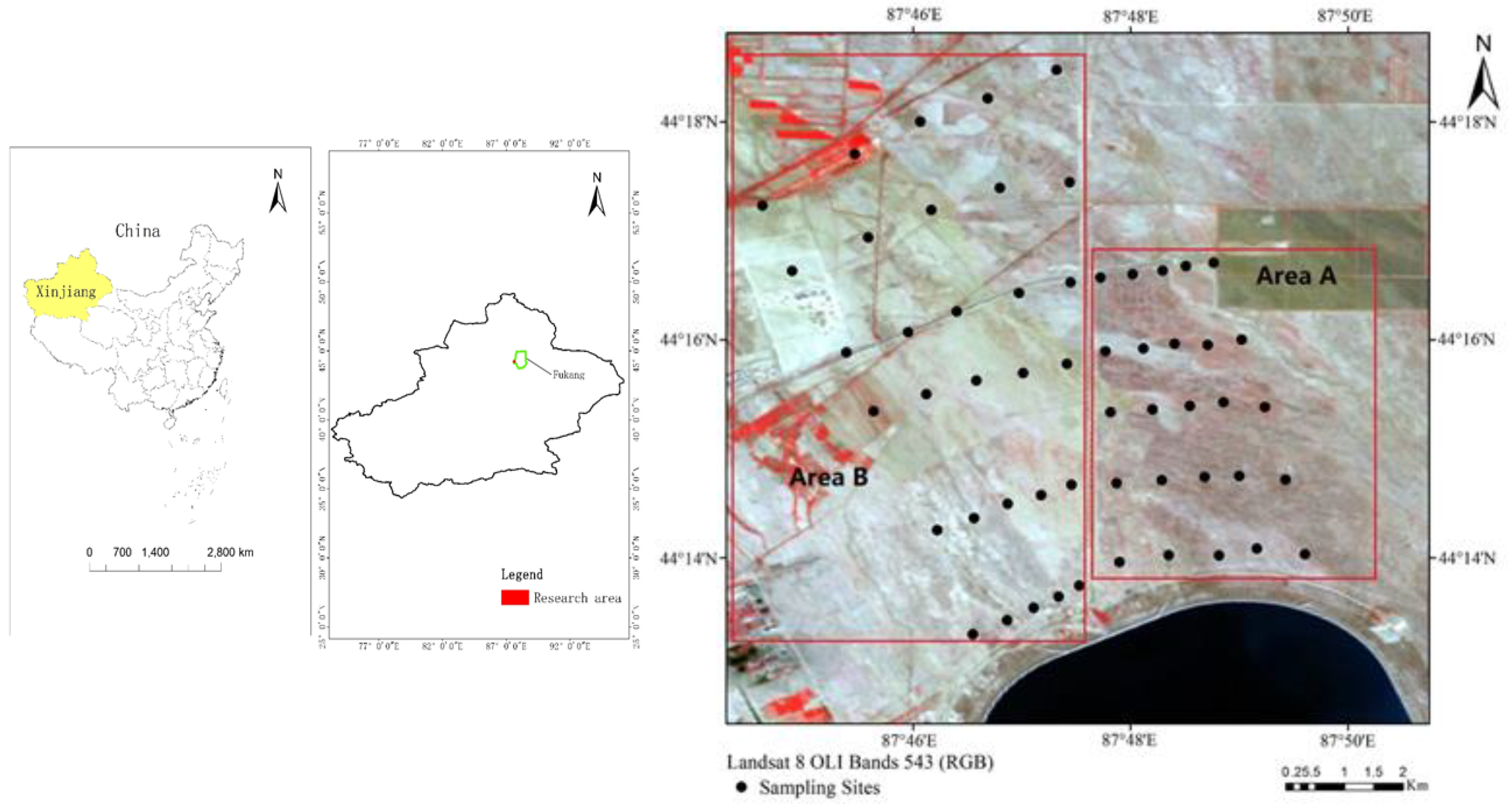
Figure 1. Research location and soil sampling point distribution.
Remotesensing 13 03819 g001
Figure 2. Area A and B spectrum reflectance. (a) Area A. (b) Area B.
Remotesensing 13 03819 g002
Figure 3. Area A and B spectrum reflectance. (a) Area A. (b) Area B.
Remotesensing 13 03819 g003
Figure 4. Chua’s circuit.
Remotesensing 13 03819 g004
Figure 5. Non-linear resistor’s characteristic curve.
Remotesensing 13 03819 g005
Figure 6. Chen−Lee chaotic system track.
Remotesensing 13 03819 g006
Figure 7. Extension set.
Remotesensing 13 03819 g007
Figure 8. Intelligent classification system architecture.
Remotesensing 13 03819 g008
Figure 9. Area A mixed chaotic system dynamic error. (a) 0.1 order; (b) 0.3 order; (c) 0.6 order; (d) 0.9 order; (e) 1 order.
Remotesensing 13 03819 g009
Figure 10. Area B mixed chaotic system dynamic error. (a) 0.1 order; (b) 0.3 order; (c) 0.6 order; (d) 0.9 order; (e) 1 order.
Remotesensing 13 03819 g010
Figure 11. Non-integer order 0.1 chaotic attractor coordinate distribution. (a) Area A. (b) Area B.
Remotesensing 13 03819 g011
Figure 12. Extension classic domain range. (a) Area A. (b) Area B.
Remotesensing 13 03819 g012
Figure 13. Extension classic domain range of the validation set.
Remotesensing 13 03819 g013
Table 1. Performance parameters of FieldSpec® 3Hi-Res.
Spectrometer ModelFieldSpec® 3Hi-Res
Spectral range350–2500 nm
Spectral resolution3 nm@700 nm
8 nm@1400/2100 nm
sampling interval1.4 nm@350–1000 nm
1.1 nm@1001–2500 nm
Equivalent noise radiationVNIR 1.0 × 10⁻⁹ W/cm2/sr@700 nm
SWIR 1.4 × 10⁻⁹ W/cm2/nm/sr/@1400 nm
SWIR 2.2 × 10⁻⁹ W/cm2/nm/sr@2100 nm
Band accuracy0.5 nm
Number of output bands2151
Detector350–1100 nm, Low-noise 512-element PDA
1000–1800 nm and 1700–2500 nm, two InGaAs detector units
In1.5 m optical fiber (25° field of view)
Table 2. Salinization classification standards.
Degree of Soil SalinizationSoil Salt Content (g/kg)
Non-saline soil<5.0
Mild saline soil5.0–10.0
Moderate saline soil10.0–15.0
Severe saline soil15.0–20.0
Saline soil>20.0
Table 3. Area A correlation level.
Sample ASaline SoilsSevere SalineMild Saline
A11−1−1
A2−11−0.06729
A3−110.099209
A4−1−0.311681
A5−1−11
Table 4. Area B correlation level.
Sample BSaline SoilsSevere SalineModerate Saline
B11−1−1
B21−0.9872−1
B3−110.3628
B4−10.17691
B5−1−11
Table 5. Comparison of soil sample chemical analysis data and extension correlation level in Area A.
Sample ASalt Content (g/kg)State
A120.075Saline soils
A218.825Severe saline
A317.050Severe saline
A46.200Mild saline
A55.150Mild saline
Table 6. Comparison of soil sample chemical analysis data and extension correlation level in Area B.
Sample ASalt Content (g/kg)State
A135.675Saline soils
A231.925Saline soils
A317.600Severe saline
A412.675Moderate saline
A511.850Moderate saline
Table 7. Comparison of extension correlation degree and salt content of the validation set.
Sample TSalt Content (g/kg)Saline SoilsSevere SalineModerate SalineMild Saline
T121.6251−1−1−1
T221.151−1−1−1
T335.6751−1−1−1
T420.4−1−1−11
T547.851−1−1−1
T628.2750.985−0.015−1−1
T719−11−1−0.0448
T816.625−10.973−1−0.027
T97.125−1−10.12560.9875
T108.425−10.036−10.964
Publisher’s Note: MDPI stays neutral with regard to jurisdictional claims in published maps and institutional affiliations.