Abstract
Ground-based synthetic aperture radar (GB-SAR) is a useful tool to simulate advanced SAR systems with its flexibility on RF system and SAR configuration. This paper reports an indoor experiment of bistatic/multistatic GB-SAR operated in Ku-band with two antennae: one antenna was stationary on the ground and the other was moving along a linear rail. Multiple bistatic GB-SAR images were taken with various stationary antenna positions, and then averaged to simulate a multistatic GB-SAR configuration composed of a moving Tx antenna along a rail and multiple stationary Rx antennae with various viewing angles. This configuration simulates the use of a spaceborne/airborne SAR system as a transmitting antenna and multiple ground-based stationary antennae as receiving antennae to obtain omni-directional scattering images. This SAR geometry with one-stationary and one-moving antennae configuration was analyzed and a time-domain SAR focusing algorithm was adjusted to this geometry. Being stationary for one antenna, the Doppler rate was analyzed to be half of the monostatic case, and the azimuth resolution was doubled. Image quality was enhanced by identifying and reducing azimuth ambiguity. By averaging multiple bistatic images from various stationary antenna positions, a multistatic GB-SAR image was achieved to have better image swath and reduced speckle noise.
1. Introduction
Conceptualization of next generation of synthetic aperture radar (SAR) often includes the use of multiple satellites for transmitting and/or receiving antennas to increase the system performance in resolution, image swath, signal-to-noise ratio, and repeated coverage [1,2,3,4,5,6,7]. One can use a satellite/airborne SAR system as a transmitter and set up multiple stationary receivers on the ground to image the surface with limited swath. Alternatively broadcasting geo-stationary satellites or GPS satellites can be used as a microwave source to image the ground nearby the stationary antenna continuously [8].
Ground-based synthetic aperture radar (GB-SAR) systems have been widely used to simulate various satellite/airborne SAR configurations for the next generation as well as its own use for ground imaging and surface change detection. Various interferometric [9,10,11,12] and tomographic SAR [13,14,15,16] have been successfully tested in GB-SAR systems owing to the highly accurate repeatability and versatile system operability. Krysik et al. [17] tested a bistatic GB-SAR configuration as a combination of GB-SAR and satellite. Pieraccini et al. [18] obtained displacement vectors of a target by redirecting the transmitted signal using a ground-based transponder. Recently, Lee and Moon [19] have tested a bistatic GB-SAR configuration where two antennae separated by a baseline are moving on a linear rail simultaneously.
In this paper, a bistatic GB-SAR system was operated in a lecture room with one antenna moving along a linear rail while the other was stationary on the ground. The RF and rail systems used in this paper were similar to [19] except for the antenna configuration. Multiple bistatic images were obtained with different positions and viewing angles of the stationary antenna in order to have SAR images with omni-directional scattering properties of a target. Those images were averaged together to simulate a multistatic GB-SAR with one-moving Tx antenna and multiple Rx antennae stationary at various locations. This configuration is quite different from other multistatic configurations such as tomographic GB-SAR that places antenna arrays in vertical directions to the SAR image plane. The system configuration and SAR geometry was analyzed in Section 2 and the resulting images were shown in Section 3. The findings and limits were discussed in Section 4 while Section 5 concludes this paper.
2. Materials and Methods
2.1. GB-SAR System with One-Stationary and One-Moving Antennae
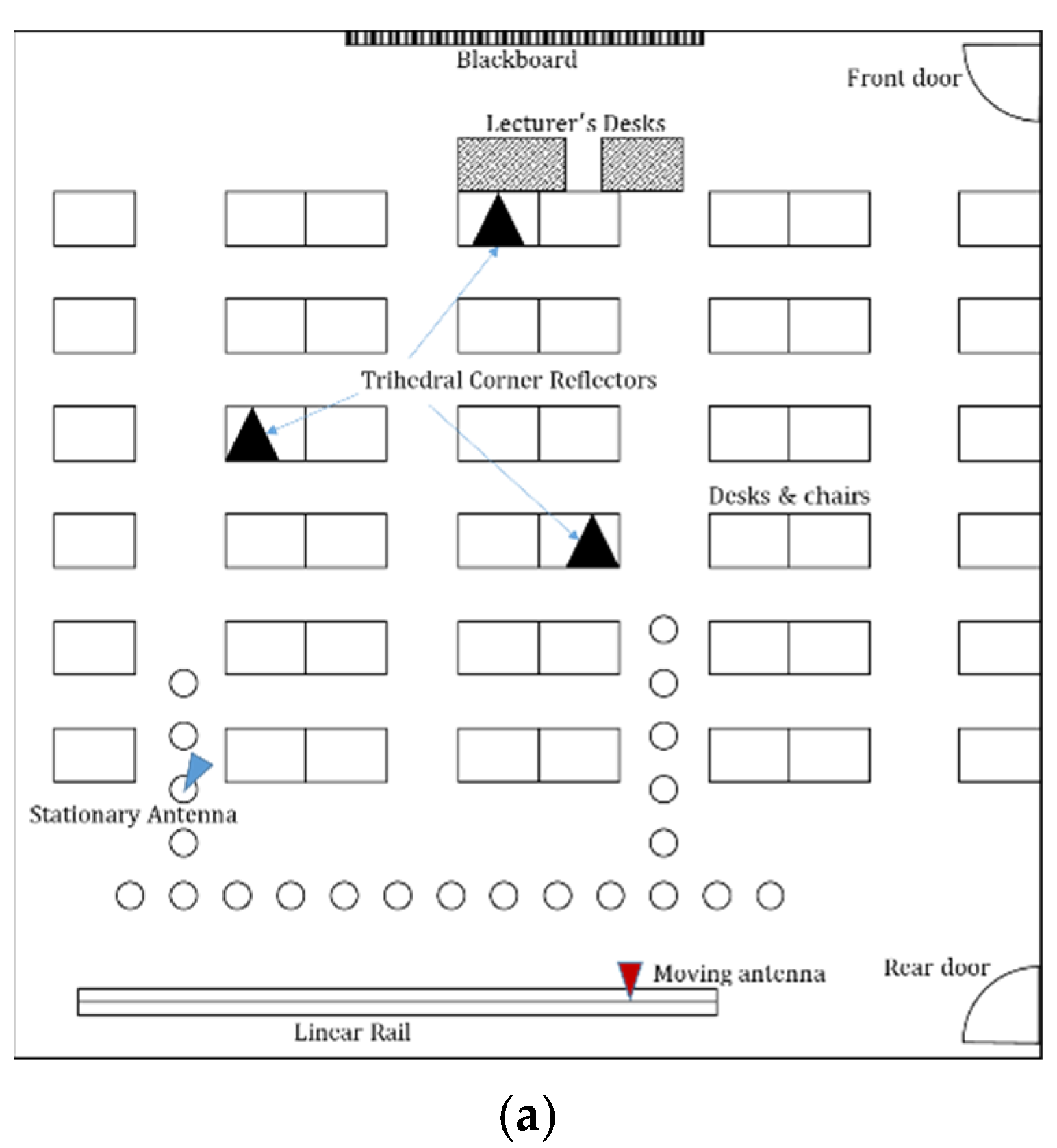
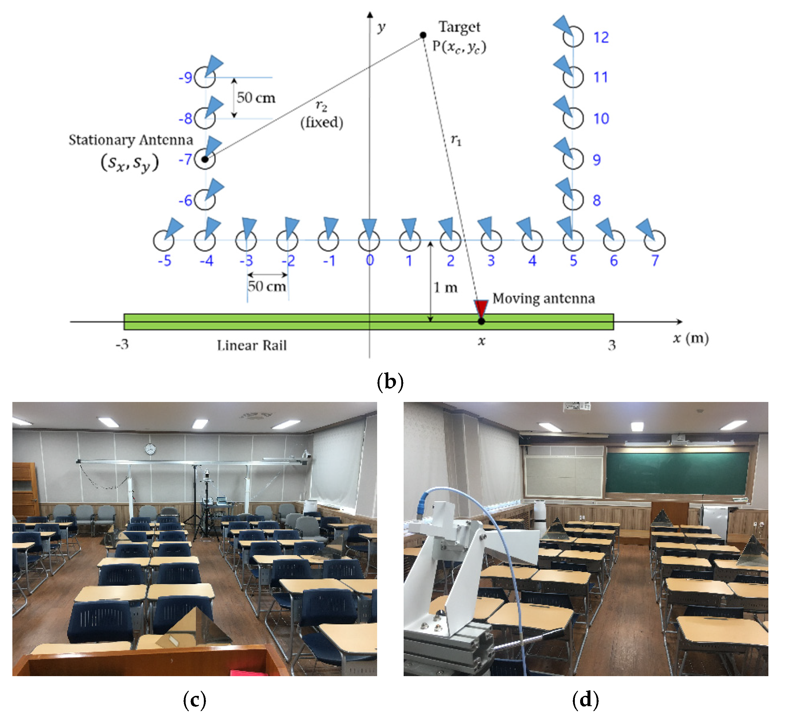
The location of the experiment and the GB-SAR system used for the one-stationary and one-moving antennae configuration in this paper was almost identical to [19]. A lecture room measured 8 m × 10 m was equipped with the array of desks and chairs, lecturer’s desks and a blackboard. Three trihedral corner reflectors (TCR) were put on the desks, as shown in Figure 1a. A linear rail system was installed at the back of the room which ensured the maximum scan length of 6 m. The rail was supported by three poles to have a height of 1.8 m from the ground. A Ku-band square horn antenna was installed on a moving platform on top of the rail. The motion of the antenna was precisely controlled by a stepping motor connected with a conveyor belt system, which provided a cumulative positional error of less than 0.1 mm. The stationary antenna that has identical specifications to the moving antenna was installed on a marked place as shown in Figure 1b. A total of 22 locations for the stationary antenna were marked on the ground. The location of the stationary antenna changed for each GB-SAR image acquisition in order to provide different viewing angles. They were separated by 50 cm with each other either in range or azimuth direction, and named from #−9 to #12, as shown in Figure 1b.
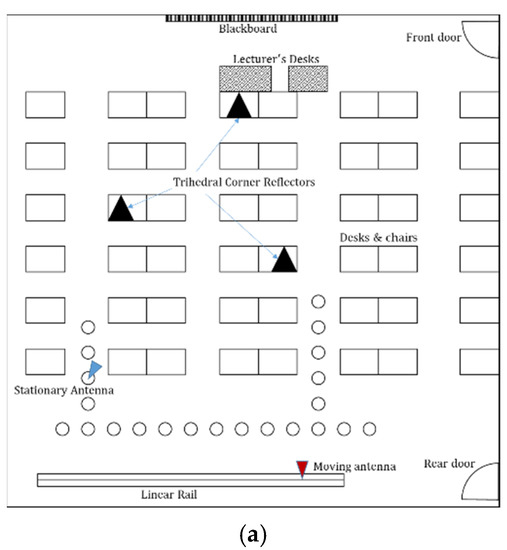
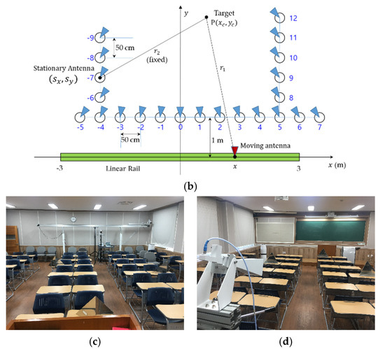
Figure 1.
A ground-based synthetic aperture radar (GB-SAR) experiment with one stationary and one moving antennae inside a lecture room. (a) a diagram of the indoor targets and system, (b) a schematic geometry of the GB-SAR configuration, (c) a photo of the system and the targets, and (d) a photo of the lecture room seen from a stationary antenna with chairs and three trihedral corner reflectors.
An Anritsu MS2028B vector network analyzer (VNA) was used for the RF system. As shown in Table 1, The VNA transmits microwave in a stepped-frequency mode with a center frequency of 15.95 GHz and bandwidth of 1.6 GHz to have a nominal range resolution of 9.4 cm in the case of monostatic radar. The azimuth scanning step is 3 cm to have 201 azimuth samples, providing azimuth resolution of 4.5 cm in the case of monostatic GB-SAR. The range and azimuth resolutions for the one stationary and one moving antenna configuration were different from monostatic GB-SAR, which will be analyzed in the following section. All the system components were lined to and controlled by a notebook computer and with data acquisition software.

Table 1.
System parameters for a bistatic/multistatic GB-SAR experiment.
2.2. SAR Image Formation
2.2.1. Range Resolution
The VNA obtains a radar signal by sweeping the frequency within the bandwidth. The returned signal is sampled as a function of frequency with a center frequency of and bandwidth . Range compression is performed by the inverse Fourier transform of the returned signal to composite a radar in time domain:
which is represented as a convolution () of the impulse response of the radar system and the radar scattering coefficient of targets . The range time resolution can be defined to be assuming a point target with a scattering coefficient of a delta function, . The (slant) range resolution is then for a monostatic radar [19].
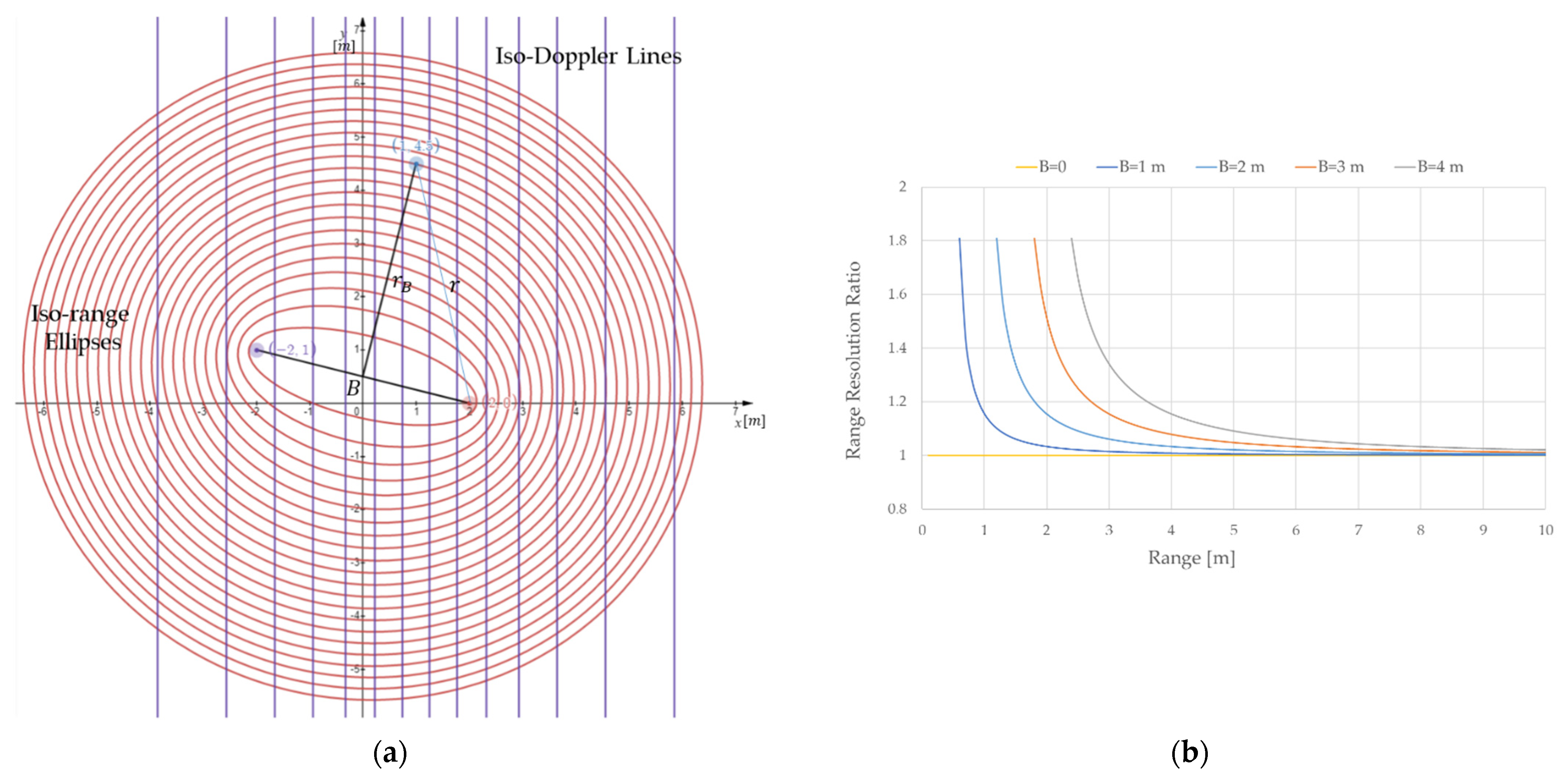
For one stationary and one moving antennae configuration in this study, the range resolution can be expressed as a bistatic case where two antennae are separated by a baseline of B as shown in Figure 2a. The iso-range planes are ellipsoids with two focal points located at each antenna position. As in [19], a bistatic range, , can be defined as a coordinate with the origin at the center of an iso-range ellipse and the direction of the semi-minor axis, so that where the monostatic range r is the distance from the antenna to a target in the direction of . The ratio of the two resolutions can be defined by [19]
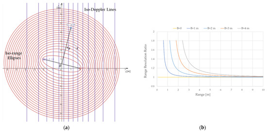
Figure 2.
Bistatic SAR geometry with one stationary and one moving antennae. (a) Iso-range ellipses with two antennae separated by B, and iso-Doppler lines for a target at (1, 4.5). (b) the ratios of range resolution for a bistatic radar over a monostatic radar () with different baselines.
As shown in Figure 2b, the bistatic range resolution is always larger than that of the monostatic case [19], and converges to the monostatic radar if or is at far range. In this experiment, the baseline is up to 6.5 m, as shown in Figure 1b. However, due to the antenna direction, the most significant contribution to the radar-returned signal happened with the baseline smaller than 4 m. Figure 2b shows that degradation of range resolution is limited within the near range of 2 m, which ensures good image quality at far range for this one stationary and one moving antennae configuration.
2.2.2. Azimuth Resolution
For a point target in Figure 1a, the received signal with a stationary antenna positioned at and a moving antenna at ( is:
where
Here, is the coherent integration length. Note that is a constant with respect to the scanning antenna position .
Azimuth focusing is performed by the following matched filtering:
where , and * is a conjugate operator. Taylor expansion of the phase in Equation (3) at gives the approximate estimation of the Equation (5).
where and are the Doppler centroid and Doppler rate. To evaluate the azimuth resolution, we need to find the Doppler parameters of this experiment. By definition, Doppler is a wavenumber defined by the change of phase with respect to .
Here, the result is only from the first derivative for the moving antenna, as for the stationary antenna. Figure 2a shows the iso-Doppler lines in (x, y) plane given by:
Note that the iso-Doppler lines are vertical lines. It is at zero-Doppler and the gaps between two iso-Doppler lines increases with both and . The Doppler centroid is then , which is the same case for other GB-SAR systems [9,14].
The derivative of Doppler is:
Doppler rate is then defined by
which is exactly half of the monostatic case in [19]. The azimuth resolution is also double the monostatic case [9], as is given by the following expression:
The coherent integration length depends on the beam width of the moving antenna, which is given as follows.
Inserting Equation (12) into (11) gives the azimuth resolution as follows.
In this experiment, we have the following resolution:
As the maximum range of the lecture room in this experiment is 10 m, the azimuth resolution in this experiment is 9 cm which is the same as the size of the real aperture of the antenna in azimuth direction. The angular azimuth resolution is 0.18° at the far range (>28.72 m) which is double the monostatic case (0.09°).
Azimuth ambiguity can arise with a separation angle of the azimuth image width, (in radian). It can be defined as a multiplication of the angular azimuth resolution at far range, , as derived by Equation (13), and the number of azimuth sampling so that:
which should be larger than the beam width of the antenna () to avoid multiples due to azimuth ambiguity. Therefore, we have
which indicates that the azimuth sampling step should be several times smaller than the antenna aperture length (L). The azimuth ambiguity and the multiples will be shown in the following results.
3. Results
Figure 3 shows the focused images of the bistatic GB-SAR experiments with one stationary and one moving antennae. The scene number in each image is the same as in Figure 1b. The location and the viewing direction of the stationary horn antenna is depicted as a triangle in each image. Note that the viewing direction of the moving antenna is fixed to the forward direction, which makes a right angle with the rail. Generally speaking, the amplitude is bright over the area where the footprints of the two antennae overlap. The overlapping area becomes wider when the stationary antenna is located near the center of the rail, such as the scenes from #−2 to #2. The image is dark at a range between the stationary antenna and the rail due to the lack of overlapping footprint of the antenna beams.
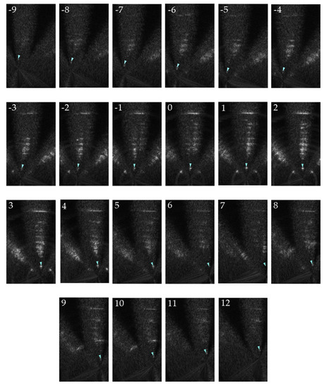
Figure 3.
Bistatic GB-SAR images with one stationary and one moving antennae. Numbers correspond to the locations of the stationary antenna in Figure 1a. The position and viewing direction of the stationary antenna is depicted in each image.
Multiples can be seen in azimuth direction due to azimuth ambiguity. This happened because we have not imposed the restriction of the coherent integration length due to the beam width, as shown in Equation (12). This was done intentionally to check if the azimuth step interval is small enough to avoid azimuth ambiguity in the image area of interest. For this experiment, the 3 dB-beam width of the horn antenna with 9 cm aperture is 11.97°. The sampling step is set to be cm, thus ° as of Equation (15), which is wide enough to avoid azimuth ambiguity. The separation angles between multiples can be widened by reducing the sampling step along the rail.
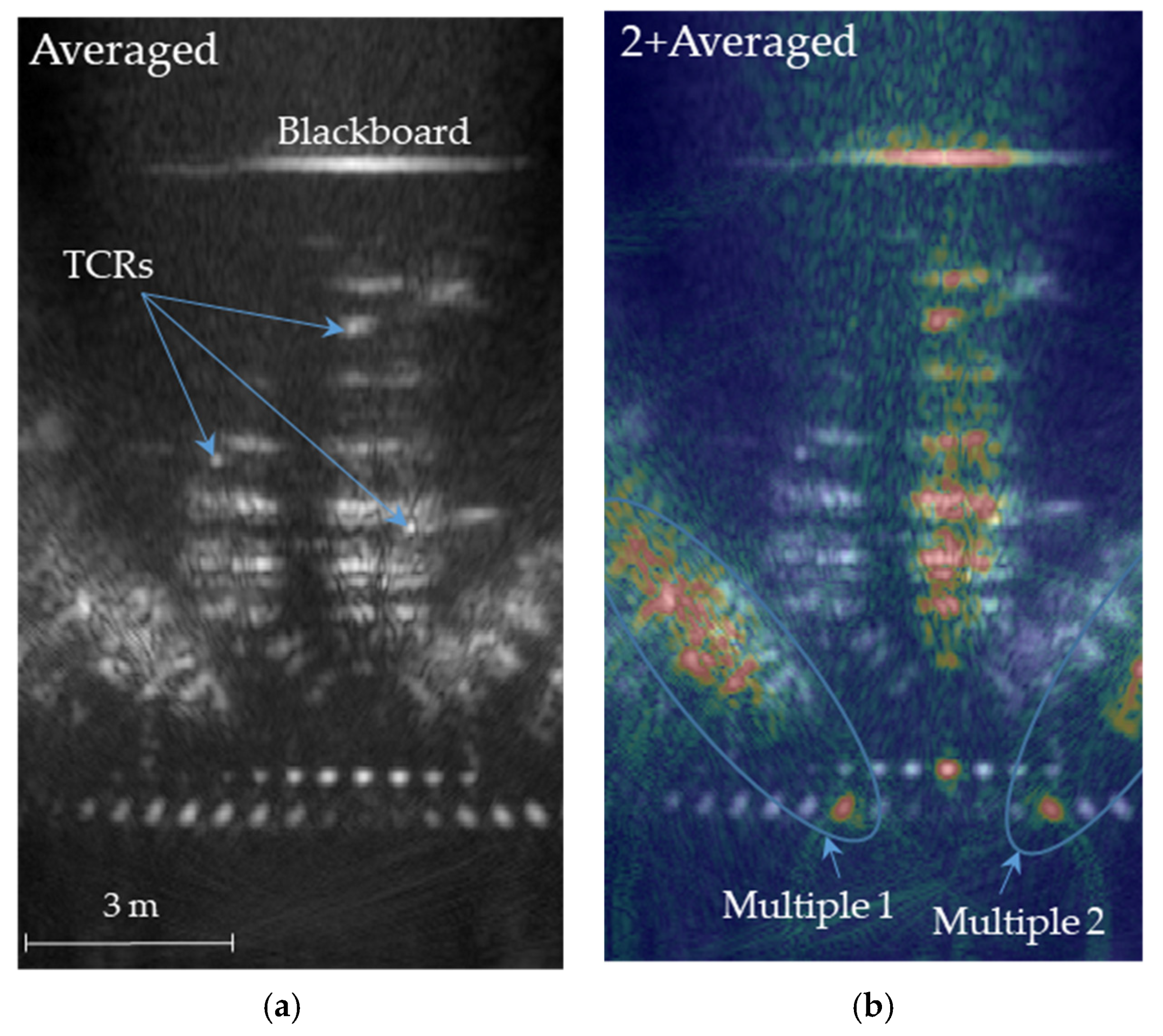
Figure 4 shows an averaged image of all the images of Figure 3 to simulate the multistatic GB-SAR configuration where multiple stationary antennae are positioned in various locations simultaneously. The moving antenna on a rail should be a transmitter while stationary antennae act as receivers when operated simultaneously. However, we have no such restriction in this simulation using bistatic GB-SAR. Figure 4a shows the average image where blackboard, desks, chairs, and three corner reflectors are clearly imaged. Figure 4b is the overlay of scene #2 over the averaged image, in which multiples can be found very easily. The angle of multiples matches with the predicted value of .

Figure 4.
Multistatic GB-SAR images: (a) An averaged image of all the images with various stationary antennae in Figure 3. (b) The scene #2 image in RGB color overlying the averaged image, showing two azimuth multiples.
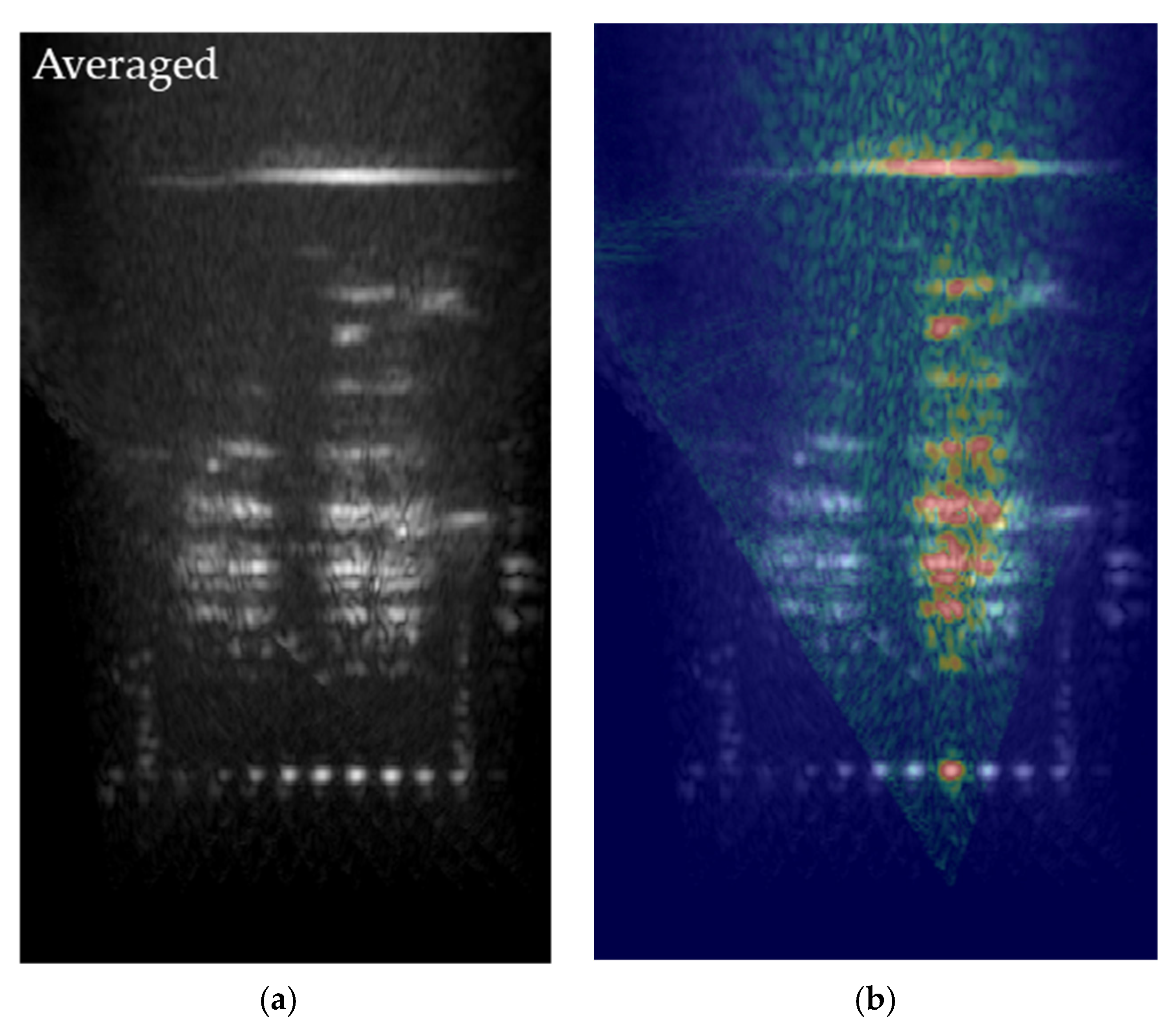
Figure 5a is the averaged image after reducing azimuth ambiguity by applying coherent integration length in Equation (12). Most of the multiples have disappeared, especially at near range where the stationary antennae were imaged without multiples.
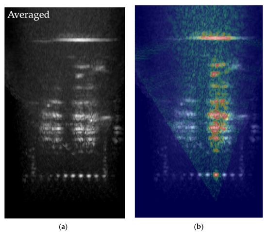
Figure 5.
Multistatic GB-SAR after removing azimuth multiples. (a) An averaged image of all the images with various stationary antennae. (b) The scene #2 image in RGB color overlying the averaged image. Note that multiples were removed successfully.
4. Discussion
This indoor experiment of bistatic GB-SAR with one stationary and one moving antennae configuration can be a good simulation of an airborne/spaceborne application where one of the two antennae needs to be a passive receiver. Range resolution of a bistatic situation with two antennae separated by a baseline is the same as the bistatic GB-SAR in [19]. Range resolution is poorer at near range and as the baseline increases, but converges to the monostatic case at far range. Azimuth resolution is twice that of monostatic GB-SAR regardless of the range. A longer rail scanning length would have resulted in better azimuth resolution while a smaller stepping step is necessary to avoid multiples from azimuth ambiguity. The imaging area is limited to the overlapping footprint of the radar beam. The proper use of the coherent integration length that corresponds to the overlapping footprint of antenna beams will reduce multiples caused by azimuth ambiguity during SAR focusing. The squint operation of the moving antenna to aim the footprint of the stationary antenna would have increased the coherent integration time of a target and improved the quality.
The averaging of the resulting images can be a simulation of multistatic GB-SAR with one moving antenna and multiple stationary antennae simultaneously. This is a good simulation of using an airborne/spaceborne satellite as a transmitter, while multiple ground antennae are located simultaneously in many locations to cover multiple areas. By averaging the images from multiple stationary receivers on the ground, one can extend the coverage of the image extensively. The reduction of speckle noise is another advantage of averaging. Moreover, a wider variation of angle between Tx, a target, and Rx would provide smoother scattering properties, not just a backscattering property of a monostatic case.
Due to the reciprocity of the radar signal, the resulting image would be the same for a bistatic GB-SAR configuration regardless of the choice of transmitting or receiving for the stationary or moving antennae. For a realistic situation of multistatic GB-SAR, however, a moving antenna needs to be a transmitter and multiple stationary antennae should be receivers to obtain an image simultaneously. This experiment is carefully designed to reduce the sidelobe effect of the antenna. Multiples from the wall in both the sides and the front have been placed so that they do not overlap with the main imaging area by adjusting sampling steps in range and azimuth. In terms of future research, an outdoor experiment is being designed where the situation would be much better in terms of ambiguities in range and azimuth.
In the case of outdoor experiments with an airborne/spaceborne vehicle, the flying vehicle will act as the transmitter and the multiple ground receivers will be placed with different look directions. The azimuth sampling step will be determined by the flying SAR settings, which should be small enough to avoid azimuth ambiguity. As analyzed in Eq. (2), range resolution will be similar to the monostatic SAR case as the range will be much larger than that of the indoor experiment. The azimuth resolution will be twice that of the monostatic case, as discussed in Equation (14). The target area will be clearly detected if the Tx and Rx beams overlap sufficiently to have coherent integration length () in Equation (13).
5. Conclusions
An indoor experiment with a bistatic GB-SAR configuration with one stationary and one moving antennae in the Ku-band was successfully performed in a conventional lecture room. The images with a stationary antenna positioned at various locations were obtained over the area that corresponds to the overlapping part of the footprints of the antennae. Averaging those images produced a high quality image with a wider imaging area and reduced speckle noise. The azimuth ambiguity was analyzed and reduced by applying the coherence integration time of the system configuration.
This experiment simulated an airborne/spaceborne bistatic/multistatic SAR configuration where only one antenna is used as a transmitter and multiple antennae can be used as receivers in passive mode. The transmitting antenna can be either stationary on the ground or moving onboard an aircraft or satellite. Multiple receiving antennae, stationary or moving, can reduce the detectability during operation.
Author Contributions
Conceptualization, H.L. and J.M.; methodology, H.L.; software, H.L.; validation, J.M.; formal analysis, H.L. and J.M.; investigation, H.L. and J.M.; resources, J.M.; data curation, J.M.; writing—original draft preparation, H.L.; writing—review and editing, H.L.; visualization, H.L. and J.M.; supervision, H.L.; project administration, H.L.; funding acquisition, H.L. All authors have read and agreed to the published version of the manuscript.
Funding
This research was supported by the Next Generation SAR Laboratory funded by Defense Acquisition Program Administration (DAPA) and Agency for Defense Development (ADD).
Institutional Review Board Statement
Not applicable.
Informed Consent Statement
Not applicable.
Data Availability Statement
The data presented in this study are available on request from the corresponding author.
Conflicts of Interest
The authors declare no conflict of interest.
References
- Krieger, G.; Moreira, A. Spaceborne bi- and multistatic SAR: Potential and challenges. IEEE Proc. Radar Sonar Navig. 2006, 153, 184–198. [Google Scholar] [CrossRef] [Green Version]
- Krieger, G.; Moreira, A.; Fiedler, H.; Hajnsek, I.; Werner, M.; Younis, M.; Zink, M. TanDEM-X: A satellite formation for high-resolution SAR interferometry. IEEE Trans. Geosci. Remote Sens. 2007, 45, 3317–3341. [Google Scholar] [CrossRef] [Green Version]
- Nies, H.; Loffeld, O.; Natroshvili, K. Analysis and focusing of bistatic SAR data. IEEE Trans. Geosci. Remote Sens. 2007, 45, 3342–3349. [Google Scholar] [CrossRef]
- Lazarov, A.; Kostadinov, T. Analytical Geometrical Determination of BSAR Resolution. In Bistatic SAR/GISAR/FISAR Geometry, Signal Models and Imaging Algorithms; John Wiley & Sons, Inc.: Hoboken, NJ, USA, 2014; pp. 65–75. [Google Scholar]
- Wang, R.; Loffeld, O.; Neo, Y.L.; Nies, H.; Dai, Z. Extending Loffeld’s bistatic formula for the general bistatic SAR configuration. IET Radar Sonar Navig. 2010, 4, 74–84. [Google Scholar] [CrossRef]
- Rodriguez-Cassola, M.; Baumgartner, S.V.; Krieger, G. Bistatic TerraSAR-X/F-SAR Spaceborne-Airborne SAR Experiment: Description, Data Processing, and Results. IEEE Trans. Geosci. Remote Sens. 2010, 48, 781–794. [Google Scholar] [CrossRef] [Green Version]
- Dubois-Fernandez, P.; Cantalloube, H.; Vaizan, B.; Krieger, G.; Horn, R.; Wendler, M.; Giroux, V. ONERA-DLR bistatic SAR campaign: Planning, data acquisition, and first analysis of bistatic scattering behaviour of natural and urban targets. IEE Proc. Radar Sonar Navig. 2006, 153, 214–223. [Google Scholar] [CrossRef] [Green Version]
- Bárcena-Humanes, J.L.; Gómez-Hoyo, P.J.; Jarabo-Amores, M.P.; Mata-Moya, D.; Del-Rey-Maestre, N. Feasibility study of EO SARs as opportunity illuminators in passive radars: PAZ-based case study. Sensors 2015, 15, 29079–29106. [Google Scholar] [CrossRef] [PubMed] [Green Version]
- Lee, H.; Cho, S.J.; Sung, N.H.; Kim, J.H. Development of a GB-SAR system (I): System configuration and interferometry. Korean J. Remote Sens. 2007, 23, 237–245. [Google Scholar]
- Lee, H.; Cho, S.J.; Sung, N.H.; Kim, J.H. Development of a GB-SAR (II): Focusing algorithms. Korean J. Remote Sens. 2007, 23, 247–256. [Google Scholar]
- Lee, H.; Lee, J.-H.; Kim, K.-E.; Sung, N.-H.; Cho, S.-J. Development of a Truck-Mounted Arc-Scanning Synthetic Aperture Radar. IEEE Trans. Geosci. Remote Sens. 2014, 52, 2773–2779. [Google Scholar] [CrossRef]
- Feng, W.; Friedt, J.; Nico, G.; Wang, S.; Martin, G.; Sato, M. Passive Bistatic Ground-Based Synthetic Aperture Radar: Concept, System, and Experiment Results. Remote Sens. 2019, 11, 1753. [Google Scholar] [CrossRef] [Green Version]
- Lee, H.; Ji, Y.; Han, H. Experiments on a Ground-Based Tomographic Synthetic Aperture Radar. Remote Sens. 2016, 8, 667. [Google Scholar] [CrossRef] [Green Version]
- Yitayew, T.G.; Ferro-Famil, L.; Eltoft, T.; Tebaldini, S. Tomographic Imaging of Fjord Ice Using a Very High Resolution Ground-Based SAR System. IEEE Trans. Geosci. Remote Sens. 2017, 55, 698–714. [Google Scholar] [CrossRef]
- Albinet, C.; Borderies, P.; Koleck, T.; Rocca, F.; Tebaldini, S.; Villard, L.; Le Toan, T.; Hamadi, A.; Ho Tong Minh, D. TropiSCAT: A ground based polarimetric scatterometer experiment in tropical forests. IEEE J. Sel. Topics Appl. Earth Obs. Remote Sens. 2012, 3, 1060–1066. [Google Scholar] [CrossRef]
- Monteith, A.R.; Ulander, L.M.H. Temporal Characteristics of P-Band Tomographic Radar Backscatter of a Boreal Forest. IEEE J. Sel. Topics Appl. Earth Obs. Remote Sens. 2021, 14, 1967–1984. [Google Scholar] [CrossRef]
- Krysik, P.; Maslikowski, L.; Samczynski, P.; Kurowska, A. Bistatic ground-based passive SAR imaging using TerraSAR-X as an illuminator of opportunity. In Proceedings of the 2013 International Conference on Radar, Adelaide, SA, USA, 9–12 September 2013; pp. 39–42. [Google Scholar]
- Pieraccini, M.; Miccinesi, L.; Rojhani, N. A GBSAR Operating in Monostatic and Bistatic Modalities for Retrieving the Displacement Vector. IEEE Geosci. Remote Sens. Lett. 2017, 14, 1494–1498. [Google Scholar] [CrossRef]
- Lee, H.; Moon, J. Analysis of a Bistatic Ground-Based Synthetic Aperture Radar System and Indoor Experiments. Remote Sens. 2021, 13, 63. [Google Scholar] [CrossRef]

Publisher’s Note: MDPI stays neutral with regard to jurisdictional claims in published maps and institutional affiliations. |
© 2021 by the authors. Licensee MDPI, Basel, Switzerland. This article is an open access article distributed under the terms and conditions of the Creative Commons Attribution (CC BY) license (https://creativecommons.org/licenses/by/4.0/).