Abstract
In this work, we propose a geodetic model for the March 2021 Thessaly seismic sequence (TSS). We used the interferometric synthetic aperture radar (InSAR) technique and exploited a dataset of Sentinel-1 images to successfully detect the surface deformation caused by three major events of the sequence and constrain their kinematics, further strengthened by seismic data analysis. Our geodetic inversions are consistent with the activation of distinct blind faults previously unknown in this region: three belonging to the NE-dipping normal fault associated with the Mw 6.3 and Mw 6.0 events, and one belonging to the SW-dipping normal fault associated with the Mw 5.6, the last TSS major event. We performed a Coulomb stress transfer analysis and a 1D pore pressure diffusivity modeling to investigate the space–time evolution of the sequence; our results indicate that the seismic sequence developed in a sort of domino effect. The combination of the lack of historical records of large earthquakes in this area and the absence of mapped surface features produced by past faulting make seismic hazard estimation difficult for this area: InSAR data analysis and modeling have proven to be an extremely useful tool in helping to constrain the rupture characteristics.
1. Introduction
The Thessaly seismic sequence (TSS), Central Greece, started on 3 March 2021 (10:16:08 UTC) with a Mw 6.3 event and struck an area about 25 km WNW of the town of Larissa (Figure 1). Fortunately, it caused no fatalities, while only three people were slightly injured due to the partial collapse of buildings with load-bearing masonry walls in the village of Damasi; moreover, widespread liquefaction phenomena were observed in the fields located close to local rivers [1]. Based on various seismological observatories and institutes (AUTH, NOA, GCMT, USGS, OCA, INGV, GFZ), the first event was characterized by a normal fault mechanism (Figure 1a). Several aftershocks (Mw > 5) concentrated to the southeast during the first few hours after the event within a distance of 10 km (Figure 1a).
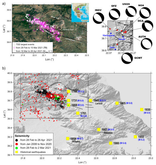
Figure 1.
Study area and seismological data. (a; left) Main tectonic lineaments redrawn after [2] and represented by black lines; relocated earthquakes from 28 February 2021 to 15 March 2021 and from 16 March 2021 to 26 April 2021, represented by magenta and white circles, respectively. (a; right) Mw 6.3 epicentral area with focal mechanisms provided by various institutes; most damaged villages are also shown. (b) Recent recorded earthquakes in the Tyrnavos area. Historical earthquakes that occurred in Thessaly area are also shown (data by [3]). Recent earthquakes occurred in an area not covered by past events, thus filling a seismic gap.
In the following days, TSS was characterized by other two major events: a Mw 6.0 on March 4 (18:38:19 UTC), which has been localized about 7 km northwest from the first event; and a Mw 5.6 on March 12 (12:57:50 UTC), localized 12 km further toward the NW. A large number of smaller events have also been recorded until mid-April when the sequence decreased in frequency and magnitude.
The Thessaly region is located at the back-arc area of the Aegean microplate and is one of the most seismically active areas of Greece [2,4]. Since 1 January 2008, more than 320 revised events have been detected from the Institute of Geodynamics—National Observatory of Athens database (IG-NOA) in the extended fault area near Tyrnavos: this background seismicity at the end of 2020 had a magnitude value ranging between 0.7 to 3.6. The seismic activity resumed on 9 January 2021, with events with a magnitude ranging between 1.5 to 2. A comprehensive description of the historical and instrumental seismicity of the area is provided in detail in [3,5].
This region is mainly characterized by NW–SE-striking normal faults, testifying an extensional stress regime with low strain rate. Several active fault zones have been detected into the central and northern part of Greece and some of them have been associated with past destructive earthquakes [6] (Figure 1b). In particular, the seismicity of the Thessaly Basin originates mainly along two fault zones: the northern one, concentrated in the Larissa plain, and a southern fault zone [7]. These two zones suggest that there has been a seismic gap in the Larissa plain [8]. Overall, the 2021 TSS sequence affected the area surrounded by past events, thus filling the gap between previous ruptures.
Concerning the structures involved in TSS, a sporadic series of NW–SE striking surface breaks were found on the mountains to the north of Zarko village [1]. Unfortunately, no tectonic ruptures were found corresponding to the Mw 6.0 and Mw 5.6 events. Therefore, the geodetic data play a crucial role in locating the faults and in better constraining their geometry.
Here, we exploit the complete dataset of Sentinel-1 (S1) InSAR measurements from both ascending and descending orbits to investigate the ground displacement field. The S1 short repeat time made it possible to isolate the three major events that characterized the sequence (Figure 2a). In addition, given the rather low magnitude of the aftershocks (Mw ≤ 5.0) compared to the main events, we assumed that they only marginally contributed to the overall surface deformation. We modeled the available InSAR deformation maps to retrieve the parameters characterizing some finite dislocation sources. Then we performed a Coulomb stress transfer and a 1D diffusivity analysis in order to investigate possible fault interactions. Finally, we highlight the key role played by the configuration of the Thessaly Basin characterized by blind faults interconnected at depth, particularly interesting from both the neotectonic and active tectonics points of view.
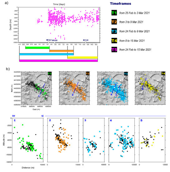
Figure 2.
Seismicity evolution. (a) Depth vs. time plot of the seismicity occurred between 28 February 2021 and 15 March 2021; some timeframes used in the subsequent discussion are also shown in different colors (T). (b) Maps and sections of the relocated seismicity plotted according to their origin time. Black dots are the relocated earthquakes recorded until 26 April 2021; subsequent earthquakes are shown with colors reflecting the introduced timeframes (from green to yellow circles). The three largest events are represented by white stars in the upper panels.
2. Exploited Data
2.1. Seismological Data
In order to constrain the geometry and location of the main fault structures involved during the TSS, we considered 1853 earthquakes that occurred in the area from 28 February 2021 to 26 April 2021 with magnitudes ranging between 0.2 and 6.3 (Figure 2). The analyzed data were collected by the Hellenic Seismic Network operated by the Institute of Geodynamics of the National Observatory of Athens (NOA-IG). For the absolute earthquake location, we used the phase readings provided by NOA-IG at 116 seismic stations (Figure S2). Our database is composed of 23,371 P- and 21,455 S-arrival times. Phase arrival times were re-weighted according to the epicentral distance provided by a preliminary location. As a result, most of the data (about 69% of P-waves and about 71% S-wave) used for absolute earthquake locations were recorded by stations located within an epicentral distance of 100 km.
Absolute earthquake locations were calculated according to a probabilistic approach using the NonLinLoc code [9] and a local 1-D velocity model [10] (see Table 1).

Table 1.
Structural model used to relocate the TSS sequence and to compute Coulomb stress change. VP = P-wave velocity, VS = S-wave velocity, ρ = density. The density was computed from vs. assuming a shear modulus of 33 GPa.
The VP/VS ratio used for the analysis was 1.78: this choice corresponds to the best value that allows to minimize the rms and location errors obtained after re-locating the data subset of the main earthquakes (MW ≥ 5.0). We obtained the mean error values, vertical, and horizontal equal to 0.67 km, 0.81 km, and a mean rms of 0.26 s, respectively. Then, we applied a double difference earthquake location technique (HypoDD [11]) to compute the earthquake relative locations that minimize the residuals between the observed and theoretical travel time differences (or double differences) for pairs of earthquakes at each station. We obtained the relative locations of 1760 earthquakes with mean errors, vertical, and horizontal, equal to 242 m and 246 m, respectively. The mean rms was 0.08 s (Figure S3). To achieve proper least squares error estimates, we followed the method proposed in [11]. The double difference earthquake locations showed a clustered seismicity, tighter along the NE–SW direction with clear earthquake alignments in vertical sections, which was not evident in the absolute catalog locations. For more details about the use of double difference technique (see the Supplementary Materials).
Earthquake locations (Figure 1 and Figure S4) suggest a 40 km NW–SE alignment, which is consistent with the regional trend of the mapped surface faults, although the earthquake clusters of 5–10 km length revealed secondary fault structures. This result is supported by the vertical section plots, which clearly show NE-dipping planes, in agreement with the retrieved focal mechanism solutions (Figure 2b). We pointed out that the continuity of these alignments seems to be interrupted laterally. As shown in Section 2 and Section 4, earthquake locations seem to show NE- and SW-dipping planes, replicating an antithetic-synthetic fault set, typical of areas involved in normal faulting. In the northern area, the earthquake location highlights a S-dipping fault plane (Section 5). Our results show a segmented fault zone with predominantly NE-trending structures and complex geometries, typical of normal fault systems as those activated by Mw 6.1 L’Aquila and Mw 6.5 Central Italy earthquakes [12,13].
2.2. InSAR Measurements
The TSS was imaged by Sentinel-1 (S1) with a regular six day repeat interval along two ascending (tracks 102 and 175) and two descending (tracks 7 and 80) orbits; we considered the interval from 24 February 2021 to 15 March 2021, which spanned the whole seismic sequence and included four acquisitions per track. The complete list of Sentinel-1 images used in this study is reported in Table S1 and are shown graphically in Figure S1, Supplementary Materials. Sentinel-1 data were processed by using our own internally developed InSAR processing chain [14,15,16].
Notably, almost simultaneous acquisitions from ascending and descending orbits were available, which may support the joint inversion of these two components of the displacement vector. A peculiarity of this S1 dataset is that the second image of track 102 was acquired just in between the first two largest earthquakes (Mw 6.3 and Mw 6.0); in this way, although they occurred only 32 h apart, we could separate the two contributions. This was not the case for the other three orbits, of which the interferograms between the first and second acquisition contained no signal and, therefore, were useless for the following analysis.
To ease the discussion, we defined several “timeframes” according to the Sentinel-1 passes and to the events they include (see colored bars in Figure 2a and Figure S1). In particular, we defined T1 and T2 as the two intervals covering the sole Mw 6.3 and Mw 6.0, respectively (Figures S5 and S6). In addition, each interferogram was uniquely labelled with a letter according to Table S1 and Figure S1.
Furthermore, we defined T3 as the timeframe interval including both the first and second main events; in this case, we had seven interferograms (blue bars in Figure 2a and Figure S1): four “long” (from end of February to 8–9 March) and three “short” interferograms (from 2–3 to 8–9 March); clearly, the short ones did not include track 102 since it covered one event only. Figure 2 shows the four T3 “long” interferograms (wrapped and unwrapped) coupled by the same acquisition times. In particular, track 102 (ascending, IW1) and track 07 (descending, IW3) are shown in the first row, while track 175 (ascending, IW3) and track 80 (descending, IW1) in the second one. These maps show three NNW–SSE striking deformation lobes located in the Larissa Basin; to the south, the two largest lobes, associated with the Mw 6.3, were evident, particularly on the descending data; this displacement pattern reached a maximum value of ~−38 cm in LOS (line-of-sight) on ascending data (negative LOS values represent increasing distances from the satellite). To the NW of this pattern, a smaller lobe relevant to the Mw 6.0 was observed. We also note that the T3 ascending pattern was quite consistent with the superimposition of T1 and T2 (Figures S5 and S6) once the different look angles were taken into account. The corresponding descending interferograms presented similar characteristics, considering the effect of opposite side views and possible horizontal components. Furthermore, we defined T4 as the interval covering the Mw 5.6 only, which was imaged once by all four tracks (yellow bars in Figure 2a and Figure S1). The corresponding wrapped and unwrapped interferograms are presented in Figure 2, showing a prevalent negative LOS displacement pattern extending along the EW direction, with a minimum of ~−10 cm, consistent with the lower energy of this event with respect to the previous ones.
Finally, we introduce T5 as the overall timeframe that includes all three main events; similarly to T3, this was formed by seven interferograms (magenta bars in Figure 2a and Figure S1), which are presented in Figures S5 and S6. Note that multiple interferograms within a single timeframe (Figure 3, Figures S5 and S6) basically comprise the same displacement signal since the four considered tracks were shifted in time by no more than one day and there was no significant activity between the end of February and the beginning of the sequence.
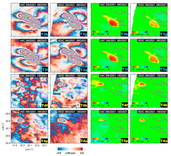
Figure 3.
InSAR interferograms. A selection of Sentinel-1 InSAR interferograms used in this study (first two columns) and corresponding unwrapped data (last two columns). Fault lineaments and epicenters of the three largest events are indicated with magenta lines and white stars, respectively. Displacements are in satellite line-of-sight (LOS).
As a further element for the interpretation, we also estimated the vertical and east–west (EW) components of the displacement [17] for each of the considered timeframes; for brevity, they are reported in Figure S7.
3. Modeling and Results
3.1. Analytical Modeling
We jointly modeled the LOS displacements retrieved from both ascending and descending InSAR data with a finite dislocation fault in an elastic and homogeneous half-space [18,19]. Our source modeling approach was based on a consolidated two-step approach, also implemented in SARscape® software, capable of computing the distribution of the (non-uniform) slip over the fault plan. The first step was implemented by fitting (via a non-linear inversion) a uniform slip model to the data to constrain the geometry of the faulting plane; in particular, it found the east, north, and depth position of the plane center, along with its strike (azimuth) and dip angles.
Clearly, this first step also provides us with an average slip value (and its rake) and with the fault plane dimensions (length and width); however, these parameters are refined afterward. In fact, the second step computes (via a linear inversion) the distribution of the slip values over the defined fault plane by partitioning it into a number of small patches; at this point, the distribution of the patches showing a significant nonzero slip defines the extension of the actual faulting portion of the plane.
We started with a non-linear inversion scheme [20,21] to identify the fault parameters and mechanism (strike, dip, rake, slip, fault location, length, depth, width) using some of the results derived from the seismic waveform analysis (e.g., strike direction or fault depth) for some inversion cases (see Figures S8, S9, S11 and S12). The optimization starts from a random fault configuration within the given parameter ranges and keeps minimizing the cost function , based on the weighted squares of the residuals between the observed and the predicted data:
where and are the observed and modeled displacements of the i-th data point, respectively; is the weighting parameter (here we assume to be the same for all points); and is the total number of points used for the inversion. The downhill algorithm is implemented with multiple restarts to guarantee the convergence to the global cost function absolute minimum.
In order to refer the source depth to the actual ground surface, we also applied a topography compensation [22] and assessed possible residual offsets and ramps in the InSAR measurements caused, for instance, by residual orbital signals [23]. Moreover, to reduce the computation load of the inversion process, the InSAR data were preliminarily down-sampled to a 140 m regular grid.
After defining the fault geometry, we applied a linear inversion to obtain the slip distribution, extending the fault length and width to let the slip vanish to zero and subdividing the fault plane into sub-faults of 0.5 × 0.5 km2. To avoid back-slip, we used a trial-and-error approach to define the system damping, which is the empirical parameter balancing the data fit and the slip distribution roughness.
The adopted linear inversion scheme is described by the equation [24,25]:
where is the InSAR data vector; is the Green’s functions matrix; and is the Laplacian operator, which is tuned with the damping factor obtained by trial-and-error [26] to obtain a reliable slip distribution, described with the m vector of parameters. A further constrain of parameter positivity was adopted to prevent back-slip.
The two timeframes that minimize the number of included events while allowing us to study the TSS deformation jointly from both ascending and descending orbits are clearly T3 and T4. We inverted for the two events (Mw 6.3 and Mw 6.0) included in T3 and, separately, for the one (Mw 5.6) included in T4 (Figures S8–S10).
The best-fitting fault model with uniform slip for T3 consists of three distinct ~58°, ~33°, and ~42° NE-dipping fault segments located beneath the three observed lobes of deformation shown in Figure 4 (say Figure 1a,b and Figure 2, respectively). They both extend to a maximum depth of 10 km, the F1a showing a small, left lateral strike-slip component (rake: −118°). Although we cannot exclude some effects on the first event, the F2 fault is interpreted as associated with the second event, as confirmed also by modeling the second event (T2) alone (see Figure S11); this showed a 13 × 3.7 km2 source plain. Conversely, data in T4 were best-fitted by a uniform slip model with a single ~47° SE-dipping fault (say F3).
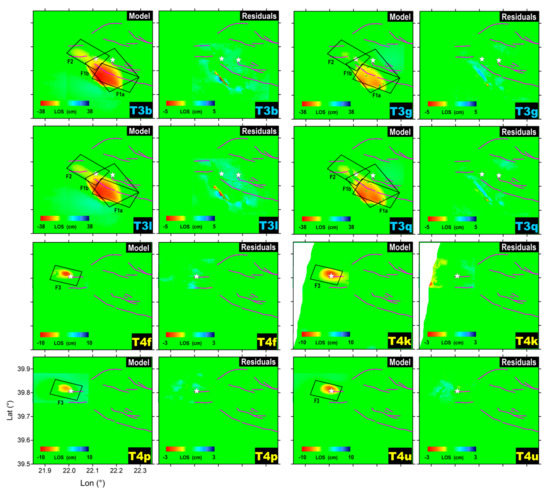
Figure 4.
Line-of-sight projected displacement maps computed from the distributed slip modeling (T3 and T4 timeframes) and corresponding residual maps for the S1 interferograms shown in Figure 3. Fault lineaments and the retrieved plain faults are indicated by magenta and black lines, respectively; white stars indicate the epicenters of the three largest events. All the uniform slip modeling results are presented in the Supplementary Materials as Figures S8–S12.
We performed uniform slip modeling for all the timeframes defined earlier; for sake of completeness, we report all these results in the Supplementary Materials in Figures S8–S12 (including inversion parameters and statistics). Our final result was achieved by constraining a small number of the model parameters either to a preliminary geodetic model or to seismic data, as explained in the following.
First, to explore the sources responsible for Mw 6.3, we chose to invert the InSAR data for the shortest allowed timeframe (i.e., T1). We noted that a single rectangular fault cannot reproduce the observed bi-lobed fringe pattern associated with this event; as a test, we performed a free inversion of T1 and found that a good fit with the data was reached only when using a two-fault model (Figure S11).
Second, we note that, while the LOS displacement profiles for the Mw 6.3 and Mw 5.6 events were very abrupt, thus clearly indicating the corresponding dipping directions, this was not the case for the Mw 6.0 event, as shown in Figure 5.
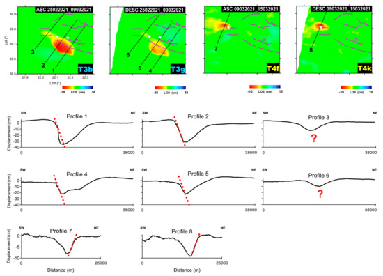
Figure 5.
Displacement maps and profiles. (Upper panels) LOS displacement maps for the indicated timeframes together with the selected profiles. (Lower panels) Displacement profiles for Mw 6.3, 6.0, and 5.6 InSAR measurement for T3 and T4; dashed red lines indicate their dipping direction. The question marks in right panels indicate that the displacement in the corresponding profiles did not allow us to discriminate the dipping of the fault plane (Mw 6.0) (see main text for the details).
It is clear, therefore, that the use of the displacement information alone makes it difficult to resolve for the F2 strike value. To overcome this problem, we thus inverted T2, constraining its depth and limiting the strike search interval according to the seismic analysis (Figure S11). Among the dislocation model parameters, the seismological analysis can provide strike and dip values, along with information about the depth. Here, we only used seismic-derived strike and depth information to guide the inversion of T2, while all the other inversions were kept free; therefore, seismic analysis data were used to independently validate the location and mechanism of the retrieved faults other than F2 (Figure 2b).
As an additional analysis, we also inverted for T5, which contained the whole sequence, by applying the same constraints used for T3 and T4; basically, we obtained the same source parameters when using a different combination of all the available interferograms covering the period (Figure S13). Subsequently, we selected the geometric settings derived from our preferred non-linear inversions (Figure S8) for the slip distribution calculation. To this end, we subdivided the fault planes into small patches (0.5 × 0.5 km2) and solved for the slip values on each patch (Figure 6).
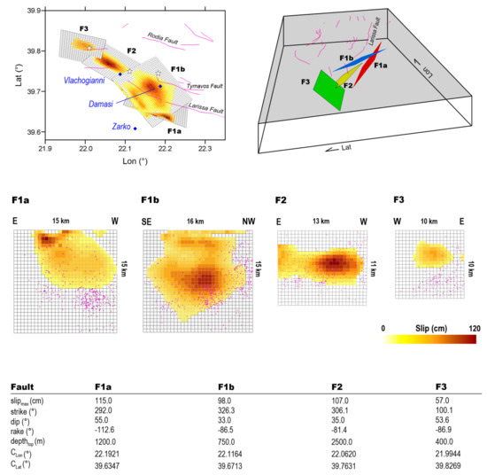
Figure 6.
Linear Inversion results. The four sources and relative retrieved parameters of the linear solutions for T3 + T4 in 2-D and 3-D views. Fault lineaments and epicenter of the three largest events are represented by magenta lines and white stars, respectively. The purple points represent all the events occurring on the fault planes.
For the Mw 6.3, the slip was concentrated between 2 km and 4 km depth: the maximum slip for F1a and F1b faults was about 1.1 m at 2 km and 4 km depths, respectively. Both fault plains present small portions of slip at shallow depths, in the area where ruptures are observed on the ground (Figure 1a). The Mw 6.0 event ruptured a western ~15 km-long segment of the F2 fault system with a maximum slip value reaching ~1.0 m at 5 km depth. Finally, the MW 5.6 ruptured the ~10 km-long segment that had remained unbroken after the previous events. We found a main patch of slip (with maximum of 0.57 m) located at the center of the fault plane at a 2.5 km depth. The overall geodetic moment of the F1 fault system was 2.88·1018 Nm corresponding to a Mw 6.3 earthquake, while for F2 and F3, we obtained 1.1·1018 Nm and 3.1·1017 Nm, corresponding to Mw 6.0 and 5.6 events, respectively. Looking at Figure 6, most of the earthquakes occurred outside or at the borders of the slipped areas on each of the fault planes. This feature suggests that some of the shear stress was redistributed outside the main patches of the slip after each event.
3.2. Coulomb Stress Transfer Analysis
To study the interaction between the three main events of the sequence, we calculated the change in the stress field on each fault plane in terms of Coulomb failure function (ΔCFF) by using an approach similar to that proposed in [27]. We calculated the co- and post-seismic deformation and the associated Coulomb stress change , where and are the shear and normal stress change, respectively; is the friction coefficient; and is the pore pressure change. We used a computer code based on the viscoelastic-gravitational dislocation theory [28] and assumed that , corresponding to drained conditions, and used . The method allowed for the use of finite source fault models with heterogeneous slip distribution. It uses the standard linear solid rheology defined by three parameters: the unrelaxed shear modulus , the viscosity , and the parameter , which is the ratio of the fully relaxed modulus to the unrelaxed modulus. As a point of difference with usual analyses that consider the location of the nucleation of the following earthquakes relative to the induced stress variation, here, we investigated the heterogeneity of the stress field on the whole fault plane and the time evolution of the earthquake preparatory process.
As undertaken for the earthquake location, we also used here the layered model proposed in [10] (see Table 1), while the detailed slip distributions and the fault geometry were those inferred from the InSAR modeling. We computed Green functions for a 10-day time window to include the effect of three main events contributing to the stress field. We used 60 equally spaced horizontal points at a distance range of 0–60 km, and 40 points in depth, ranging between 0 and 20 km. Stress field variation was computed on 16 different layers with depths ranging between 0 and 15 km.
We first considered the effect of the Mw 6.3 event on the fault planes of Mw 6.0 and Mw 5.6. Next, we considered the additional effect of the Mw 6.0 event on the fault plane of the Mw 5.6 earthquake. The first interaction is shown in Figure 7a,b while the second is shown in Figure 7c. The results reported in Figure 7a indicate that the Mw 6.3 earthquake strongly affected the Mw 6.0 by producing a significant ΔCFF increase both east and west of the hypocenter and a slighter increase in the upper right corner that likely promoted its next breaking. Similarly, the Mw 6.3 also increased the ΔCFF in the lower part of the fault plane of the Mw 5.6. The occurrence of the Mw 6.0 increased the ΔCFF in the central part of the fault, leading to the following breaking; notably, the earthquakes that occurred before the Mw 6.0 (reported as square in Figure 7a) seemed to encircle the patches that will slip. Moreover, all the aftershocks (reported as crosses in Figure 7a) occurred in the area that was initially inhibited by the ΔCFF and where remaining stress was released after the main event. Although less evident, a similar picture is depicted in Figure 7c for the Mw 5.6.
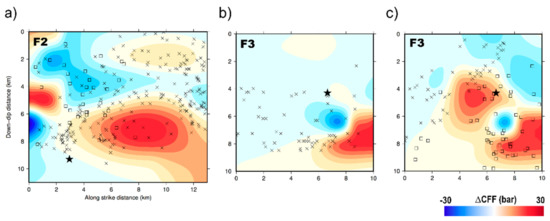
Figure 7.
Coulomb stress transfer analysis. (a) ΔCFF on the fault plane of the Mw 6.0 caused by the Mw 6.3. The squares represent all the events occurring on the fault plane (at distance of 1 km) of the Mw 6.0 before its origin time; the crosses represent all the events following its origin time. (b) ΔCFF contribution of the Mw 6.3 on the fault plane of the Mw 5.6. (c) Cumulative ΔCFF of both the Mw 6.3 and the Mw 6.0 earthquakes on the fault plane of the Mw 5.6. In each panel, the star identifies the hypocenter of the corresponding earthquake.
3.3. Diffusivity Analysis
The results reported in the previous section suggest a clear static stress contribution to the evolution of the seismic sequence. However, in order to further investigate the delayed triggering of the main events, we tested the hypothesis of pore pressure diffusion from the region enclosing the TSS. To this aim, we modeled the pore pressure perturbation caused by a point source in an isotropic fluid saturated medium. We considered the Mw 6.3 as the source and retrieved the best 1D isotropic diffusivity value (Diso) following the approach proposed in [29]. According to [30], the triggering front was modeled as , where is the scalar diffusivity corresponding to Diso/4. We only analyzed events with magnitude larger than the minimum magnitude of completeness that corresponds to Mc 1.6 ± 0.2 and was obtained by using the maximum curvature approach [31].
The resulting plot is shown in Figure 8 and the inferred best Diso was 60 ± 37 m2/s. A similar value has been obtained for the 2009 L’Aquila sequence in Italy [32].
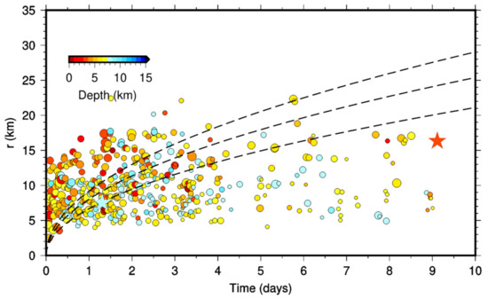
Figure 8.
r-t plot for the relocated TSS seismic sequence. Only earthquakes with magnitude larger than the minimum magnitude of completeness (Mc 1.6) were considered. The dashed lines correspond to the triggering front evaluated by using the inferred diffusivity value 60 ± 37 m2/s and plus/minus one standard deviation. Symbols dimension is proportional to the event magnitude and color coded according to the depth. The two stars indicate the Mw 6.3 (light blue) and Mw 5.6 (orange), respectively.
We note that, except for the very early days after the main event where aftershocks are expected to occur mainly due a redistribution of the stress on the fault planes, the evolution of the whole sequence is compatible with a pore pressure diffusion mechanism likely due to the volume deformation produced by the two main events. In particular, the Mw 6.0 and the Mw 5.6 occurred in correspondence with a triggering front characterized by the lower limit of the inferred diffusivity values (Figure 8).
4. Discussion
The TSS represents the largest seismic sequence affecting a continental extensional domain in Greece that has been widely monitored by modern geodetic techniques; thanks to the short satellite revisit time, InSAR measurements allowed for isolating the contribution from the major earthquakes of the sequence to study their interaction. Available geological data indicate that the northern sector of Thessaly represents a large seismic gap. This may be a direct consequence of the limited size of the faults (less than 20 km) and their intrinsic capability to originate earthquakes of small-to-moderate magnitude only [8]. TSS, which finally filled the gap, confirmed this hypothesis.
Our model shows that the seismic activity distributed along distinct segments of a previously unknown fault system composed of three fault plains (F1a, F1b, and F2) dipping NE for the Mw 6.3 and Mw 6.0 earthquakes, and of a small fault (F3) dipping SW for the Mw 5.6 (Figure 6). However, the activation of some portion of the known Tyrnavos and Larissa fault during the aftershocks cannot be completely ruled out. The orientation of the retrieved fault plains is in good agreement with the published focal mechanisms by Greek and other international Institutes (Figure 1a), and is in accordance with the extensional tectonic regime of the area.
For the first two events, the vertical deformation component highlights strong subsidence phenomena reaching more than ~40 cm. Moreover, to make the whole picture more complicated, the E–W component showed significant westward motion (~20 cm) (Figure S7). This latter motion can be related to the movement of the F1a fault, which features a slight left lateral strike-slip component.
Extensive and deep ground cracks generated by the Mw 6.3 were observed close to river beds along with ejected liquefied material; other cracks were parallel to the Vlachogianni fault. Some field reports showed scattered surface alignments only in the Zarko region [1], which can hardly be associated with faults. However, the inferred slip distribution showed that the highest values were confined in the S–E area (Vlachogianni, Damasi, Zarko villages) and this could explain the observed damage distribution (Figure 1a and Figure 6).
Our ΔCFF results (Figure 7) indicate that the seismic sequence developed in a sort of domino effect. Regarding the temporal evolution of the sequence, the delayed triggering of the Mw 6.0 earthquake can be explained by the distribution of the events that occurred earlier; indeed, that distribution envelops the patches of the fault that will break a feature, described in [33] as the encircling maneuver. A discrimination between the three main conceptual models—cascade-up, pre-slip and progressive localization [34,35]—for earthquake initiation would require a specific spatial-temporal analysis of the earthquakes sequence and stress perturbations between different events, which is beyond the scope of the present manuscript. We thus suggest that the most plausible initiation mechanism could be the recently proposed mixed stress loading process involving the cascade-triggering and aseismic-slip transient mechanisms [36].
As for the Mw 5.6 earthquake, the results depicted in Figure 7b,c show that the most relevant effect, in terms of static stress contribution, was due to the Mw 6.0 event. Furthermore, the delay in the triggering (about eight days from the Mw 6.3 and Mw 6.0 events) suggests that mechanisms other than the static stress change—in addition to a dynamic triggering contribution—took place. This is the case, for example, of pore fluid pressure diffusion as observed in other seismic sequences [37,38,39]. Indeed, a pore pressure increase can reduce the normal stress promoting the rupture. Moreover, fluids can also contribute to decreasing the fault friction [40]. The performed 1D diffusivity analysis indicates that almost all the sequence, and in particular the occurrence of the Mw 6.0 and Mw 5.6, are indeed compatible with a mechanism of pore pressure diffusion that was triggered by the deformation pattern produced by the previous events.
The combination of the lack of historical records of large earthquakes in this area, and the absence of mapped surface features produced by past faulting, make seismic hazard estimation difficult. Therefore, the identification of blind faults may significantly contribute to improve the seismic hazard analysis, particularly when dealing with moderate dip angles. In this context, the InSAR products have proven to be an extremely useful tool in helping to constrain the rupture characteristics.
Considering the possible presence of a multi-fault rupturing structure and the complexity of the tectonic framework of the studied area, we believe that the study of the seismogenic mechanism of the blind faulting deserves further investigation through additional data.
5. Conclusions
In this work, we studied the seismic sequence occurred in Thessaly (Greece) during the early days of March 2021. To this end, we used seismic and InSAR data to set up a geodetic model of the causative faulting system. Moreover, we performed Coulomb stress transfer and 1D pore pressure diffusivity analyses to investigate the space–time evolution of the sequence.
Our main findings are summarized as follows:
- the Thessaly seismic sequence nucleated at shallow depths (<12 km) and is related to the activation of several blind, previously unknown faults;
- the seismic sequence developed in a sort of domino effect involving a complex interaction among the normal faults within the activated crustal volume;
- InSAR data and modeling are also extremely useful to constrain the rupture characteristics in the case of blind faults; and
- the used approach can help improve our knowledge of the seismic potential of the Thessaly region and refine the associated seismic hazard.
Supplementary Materials
The following are available online at https://www.mdpi.com/article/10.3390/rs13173410/s1, Table S1: InSAR data parameters, Figure S1: Magnitude and time span for seismic activity and coseismic InSAR data pairs, Figure S2: Seismic stations used for earthquake locations, Figure S3: Error histograms for earthquake relocations, Figure S4: Map of the relocated epicenters, Figure S5: Additional Sentinel-1 interferograms (wrapped), Figure S6: Additional Sentinel-1 interferograms (unwrapped), Figure S7: E–W and vertical displacement maps computed from InSAR data, Figure S8: Uniform slip modeling for T3 (b + g + l + q, jointly) and T4 (f + k + p + u, jointly); Figure S9: Uniform slip modeling for T3 (b + g and l + q); Figure S10: Uniform slip modeling for T4 (f + k and p + u); Figure S11: Uniform slip modeling for T1 (a) and T2 (d); Figure S12: Uniform slip modeling for T5 (c + h and m + r).
Author Contributions
V.D.N., V.C. and E.S. conceived the paper; D.R. and E.S. processed InSAR data; G.M.A. processed the seismological data; V.D.N. performed the geodetic modeling; V.C. performed the Coulomb stress transfer and diffusivity analyses; V.D.N., V.C. and E.S. wrote the manuscript. All authors have read and agreed to the published version of the manuscript.
Funding
This study was partially funded by Pianeta Dinamico—Working Earth INGV-MUR Project.
Institutional Review Board Statement
Not applicable.
Informed Consent Statement
Not applicable.
Data Availability Statement
All the datasets generated and/or analyzed during the present study are available in the Zenodo repository (doi:10.5281/zenodo.5016812).
Acknowledgments
Sentinel-1 data were provided through the Copernicus Program of the European Union. We used the SRTM 1 arc-second DEM. Figure 7a–c were generated with Generic Mapping Tools [41].
Conflicts of Interest
The authors declare no conflict of interest.
References
- Lekkas, E.; Agorastos, K.; Mavroulis, S.; Kranis, C.; Skourtsos, E.; Carydis, P.; Gogou, M.; Katsetsiadou, K.-N.; Papadopoulos, G. The early March 2021 Thessaly earthquake sequence. In Newsletter of Environmental, Disaster and Crises Management Strategies; National and Kapodistrian University of Athens: Athens, Greece, 2021; p. 195. [Google Scholar] [CrossRef]
- Caputo, R.; Pavlides, S. Late Cainozoic geodynamic evolution of Thessaly and surroundings (central-northern Greece). Tectonophys 1993, 223, 339–362. [Google Scholar] [CrossRef]
- Caputo, R.; Helly, B.; Pavlides, S.; Papadopoulos, G. Archaeo- and palaeoseismological investigationsin Northern Thessaly (Greece): Insights for the seismic potential of the region. Nat. Haz. 2006, 39, 195–212. [Google Scholar] [CrossRef]
- Caputo, R.; Bravard, J.-P.; Helly, B. The Pliocene-quaternary tecto-sedimentary evolution of the Larissa Plain (Eastern Thessaly, Greece). Geodin. Acta 1994, 7, 57–85. [Google Scholar] [CrossRef]
- Caputo, R.; Helly, B. The Holocene activity of the Rodià Fault, Central Greece. J. Geodyn. 2005, 40, 153–169. [Google Scholar] [CrossRef]
- Caputo, R.; Pavlides, S. The Greek Database of Seismogenic Sources (GreDaSS), Version 2.0.0: A Compilation of Potential Seismogenic Sources (Mw > 5.5) in the Aegean Region; CINECA IRIS: Bologna, Italy, 2013. [Google Scholar] [CrossRef]
- Caputo, R.; Piscitelli, S.; Oliveto, A.; Rizzo, E.; Lapenna, V. The use of electrical resistivity tomography in active tectonics. Examples from the Tyrnavos Basin, Greece. J. Geodyn. 2003, 36, 19–35. [Google Scholar] [CrossRef]
- Caputo, R. Inference of a seismic gap from geological data: Thessaly (Central Greece) as a case study. Ann. Geofis. 1995, 38. [Google Scholar] [CrossRef]
- Lomax, A.; Virieux, J.; Volant, P.; Berge-Thierry, C. Probabilistic earthquake location in 3D and layered models. In Advances in Seismic Event Location; Springer: Dordrecht, The Netherlands, 2000; pp. 101–134. [Google Scholar]
- Papadimitriou, P.; Kaviris, G.; Makropoulos, K. The Cornet seismological network: 10 years of operation, recorded seismicity and significant applications. Hell. J. Geosci. 2010, 45, 193–208. [Google Scholar]
- Waldhauser, F.; Ellsworth, W.L. A double-difference earthquake location algorithm: Method and application to the northern Hayward fault, California. Bull. Seismol. Soc. Am. 2000, 90, 1353–1368. [Google Scholar] [CrossRef]
- Chiaraluce, L.; Valoroso, L.; Piccinini, D.; Di Stefano, R.; De Gori, P. The anatomy of the 2009 L’Aquila normal fault system (central Italy) imaged by high resolution foreshock and aftershock locations. J. Geophys. Res. Solid Earth 2011, 116. [Google Scholar] [CrossRef]
- Chiaraluce, L.; Di Stefano, R.; Tinti, E.; Scognamiglio, L.; Michele, M.; Casarotti, E.; Marzorati, S. The 2016 central Italy seismic sequence: A first look at the mainshocks, aftershocks, and source models. Seismol. Res. Lett. 2017, 88, 757–771. [Google Scholar] [CrossRef]
- Sansosti, E.; Berardino, P.; Manunta, M.; Serafino, F.; Fornaro, G. Geometrical SAR image registration. IEEE Trans. Geosci. Remote Sens. 2006, 44, 2861–2870. [Google Scholar] [CrossRef]
- Fornaro, G.; Sansosti, E. A two-dimensional region growing least squares phase unwrapping algorithm for interferometric SAR processing. IEEE Trans. Geosci. Remote Sens. 1999, 37, 2215–2226. [Google Scholar] [CrossRef]
- Fornaro, G.; Pauciullo, A.; Reale, D. A Null-Space Method for the Phase Unwrapping of Multitemporal SAR Interferometric Stacks. IEEE Trans. Geosci. Remote Sens. 2011, 49, 2323–2334. [Google Scholar] [CrossRef]
- Wright, T.J.; Parsons, B.E.; Lu, Z. Toward mapping surface deformation in three dimensions using InSAR. Geophys. Res. Lett. 2004, 31, L01607. [Google Scholar] [CrossRef] [Green Version]
- Okada, Y. Surface deformation due to shear and tensile faults in a half-space. Bull. Seismol. Soc. Am. 1985, 75, 1135–1154. [Google Scholar] [CrossRef]
- Okada, Y. Internal deformation due to shear and tensile faults in a half-space. Bull. Seismol. Soc. Am. 1992, 82, 1018–1040. [Google Scholar]
- Levenberg, K. A method for the solution of certain problems in least squares. Q. Appl. Math. 1944, 2, 164–168. [Google Scholar] [CrossRef] [Green Version]
- Marquardt, D. An algorithm for least-squares estimation of nonlinear parameters. SIAM J. Soc. Ind. Appl. Math. 1963, 11, 431–441. [Google Scholar] [CrossRef]
- Williams, C.A.; Wadge, G. An accurate and efficient method for including the effects of topography in three-dimensional elastic models of ground deformation with applications to radar interferometry. J. Geophys. Res. 2000, 105, 8103–8120. [Google Scholar] [CrossRef]
- Pepe, A.; Berardino, P.; Bonano, M.; Euillades, L.D.; Lanari, R.; Sansosti, E. SBAS-based satellite orbit correction for the generation of DInSAR time-series: Application to RADARSAT-1 data. IEEE Trans. Geosci. Remote Sens. 2011, 49, 5150–5165. [Google Scholar] [CrossRef]
- Atzori, S.; Hunstad, I.; Chini, M.; Salvi, S.; Tolomei, C.; Bignami, C.; Stramondo, S.; Trasatti, E.; Antonioli, A.; Boschi, E. Finite fault inversionof DInSAR coseismic displacement of the 2009 L’Aquila earthquake (central Italy). Geophys. Res. Lett. 2009, 36, L15305. [Google Scholar] [CrossRef]
- De Novellis, V.; Atzori, S.; De Luca, C.; Manzo, M.; Valerio, E.; Bonano, M.; Cardaci, C.; Castaldo, R.; Di Bucci, D.; Manunta, M.; et al. DInSAR analysis and analytical modeling of Mount Etna displacements: The December 2018 volcano-tectonic crisis. Geophys. Res. Lett. 2019, 46, 5817–5827. [Google Scholar] [CrossRef] [Green Version]
- Menke, W. Geophysical Data Analysis: Discrete Inverse Theory; Academic Press: Cambridge, MA, USA, 1989. [Google Scholar]
- Pino, N.A.; Convertito, V.; Madariaga, R. Clock advance and magnitude limitation through fault interaction: The case of the 2016 central Italy earthquake sequence. Sci. Rep. 2019, 9, 5005. [Google Scholar] [CrossRef] [PubMed] [Green Version]
- Wang, R.; Lorenzo-Martin, F.; Roth, F. PSGRN/PSCMP—A new code for calculating co- and post-seismic deformation, geoid and gravity changes based on the viscoelastic-gravitational dislocation theory. Comput. Geosci. 2006, 32, 527–541. [Google Scholar] [CrossRef] [Green Version]
- Noir, J.; Jacques, E.; Bekri, S.; Adler, P.M.; Tapponier, P.; King, G.C.P. Fluid flow triggered migration of events in the 1989 Dobi earthquake sequence of central Afar. Geophys. Res. Lett. 1997, 24, 2335–2338. [Google Scholar] [CrossRef]
- Shapiro, S.; Patzig, R.; Rothert, E.; Rindschwentner, J. Triggering of Seismicity by Pore-pressure Perturbations: Permeability-related Signatures of the Phenomenon. Pure Appl. Geophys. 2003, 456, 1051–1066. [Google Scholar] [CrossRef]
- Wiemer, S.; Wyss, M. Minimum magnitude of complete reporting in earthquake catalogs: Examples from Alaska, the western United States, and Japan. Bull. Seismol. Soc. Am. 2000, 90, 859–869. [Google Scholar] [CrossRef]
- Malagnini, L.; Lucente, F.P.; De Gori, P.; Akinci, A.; Munafo’, I. Control of pore fluid pressure diffusion on fault failure mode: Insights from the 2009 L’Aquila seismic sequence. J. Geophys. Res. 2012, 117, B05302. [Google Scholar] [CrossRef]
- Das, S.; Kostrov, B.V. Breaking of a single asperity: Rupture process and seismic radiation. J. Geophys. Res. 1983, 88, 4277–4288. [Google Scholar] [CrossRef]
- Gomberg, J. Unsettled earthquake nucleation. Nat. Geosci. 2018, 11, 463–464. [Google Scholar] [CrossRef]
- Abercrombie, R.E. Similar starts for small and large earthquakes. Nature 2019, 573, 42–43. [Google Scholar] [CrossRef] [PubMed] [Green Version]
- Kato, A.; Ben-Zion, Y. The generation of large earthquakes. Nat. Rev. Earth Environ. 2021, 2, 26–39. [Google Scholar] [CrossRef]
- Gavrilenko, P. Hydromechanical coupling in response to earthquakes: On the possible consequences for aftershocks. Geophys. J. Int. 2005, 161, 113–129. [Google Scholar] [CrossRef] [Green Version]
- Tung, S.; Masterlark, T. Delayed poroelastic triggering of the 2016 October Visso earthquake by the August Amatrice earthquake, Italy. Geophys. Res. Lett. 2018, 45, 2221–2229. [Google Scholar] [CrossRef]
- Convertito, V.; De Matteis, R.; Improta, L.; Pino, N.A. Fluid-Triggered Aftershocks in an Anisotropic Hydraulic Conductivity Geological Complex: The Case of the 2016 Amatrice Sequence, Italy. Front. Earth Sci. 2020, 8, 541323. [Google Scholar] [CrossRef]
- Scholz, C.H. The Mechanics of Earthquakes and Faulting, 2nd ed.; Cambridge University Press: Cambridge, UK, 2002. [Google Scholar]
- Wessel, P.; Smith, W.H.F. Free software helps map and display data. EOS Trans. AGU 1991, 72, 445–446. [Google Scholar] [CrossRef]
Publisher’s Note: MDPI stays neutral with regard to jurisdictional claims in published maps and institutional affiliations. |
© 2021 by the authors. Licensee MDPI, Basel, Switzerland. This article is an open access article distributed under the terms and conditions of the Creative Commons Attribution (CC BY) license (https://creativecommons.org/licenses/by/4.0/).