
Calibration Method of Array Errors for Wideband MIMO Imaging Radar Based on Multiple Prominent Targets


Abstract
:1. Introduction
2. Modeling and Analysis of Array Errors
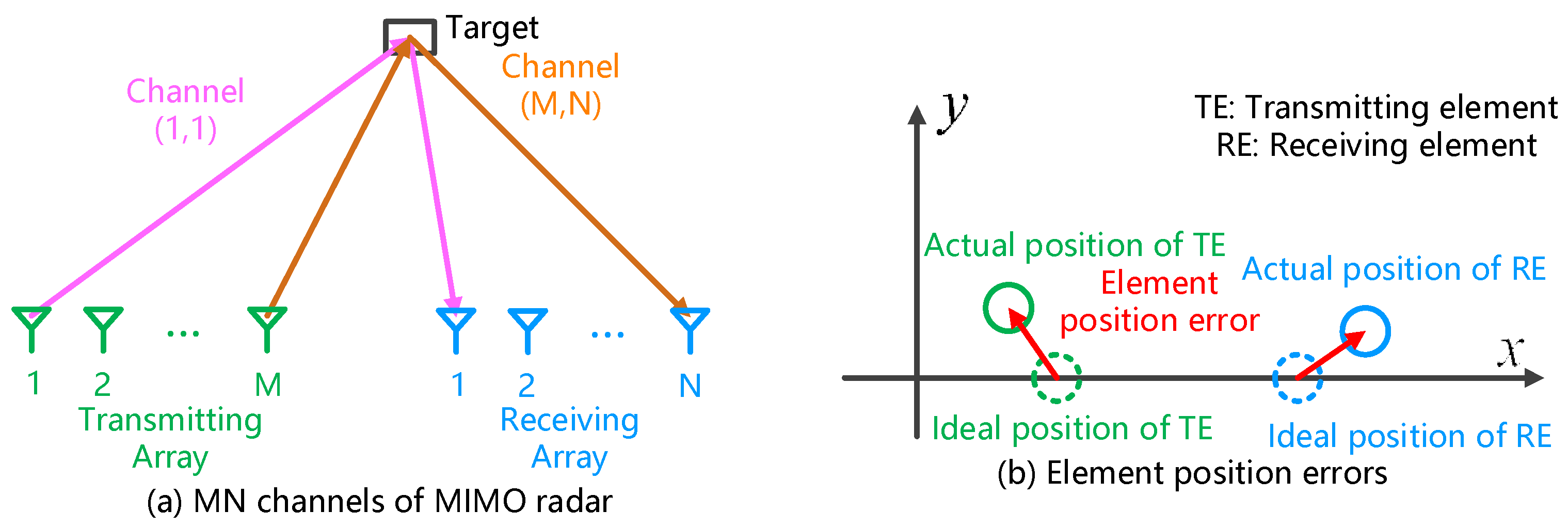
2.1. Error Classification and Echo Modeling
2.2. Characteristics of Element Position Error
3. Array Errors Calibration Based on Multiple Prominent Targets
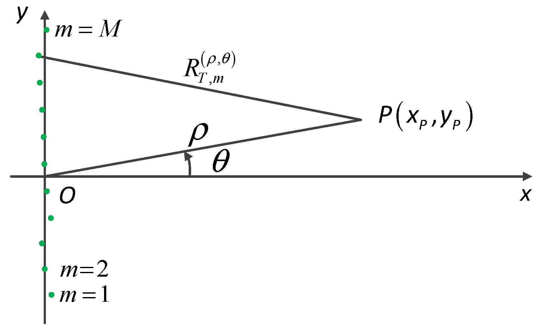
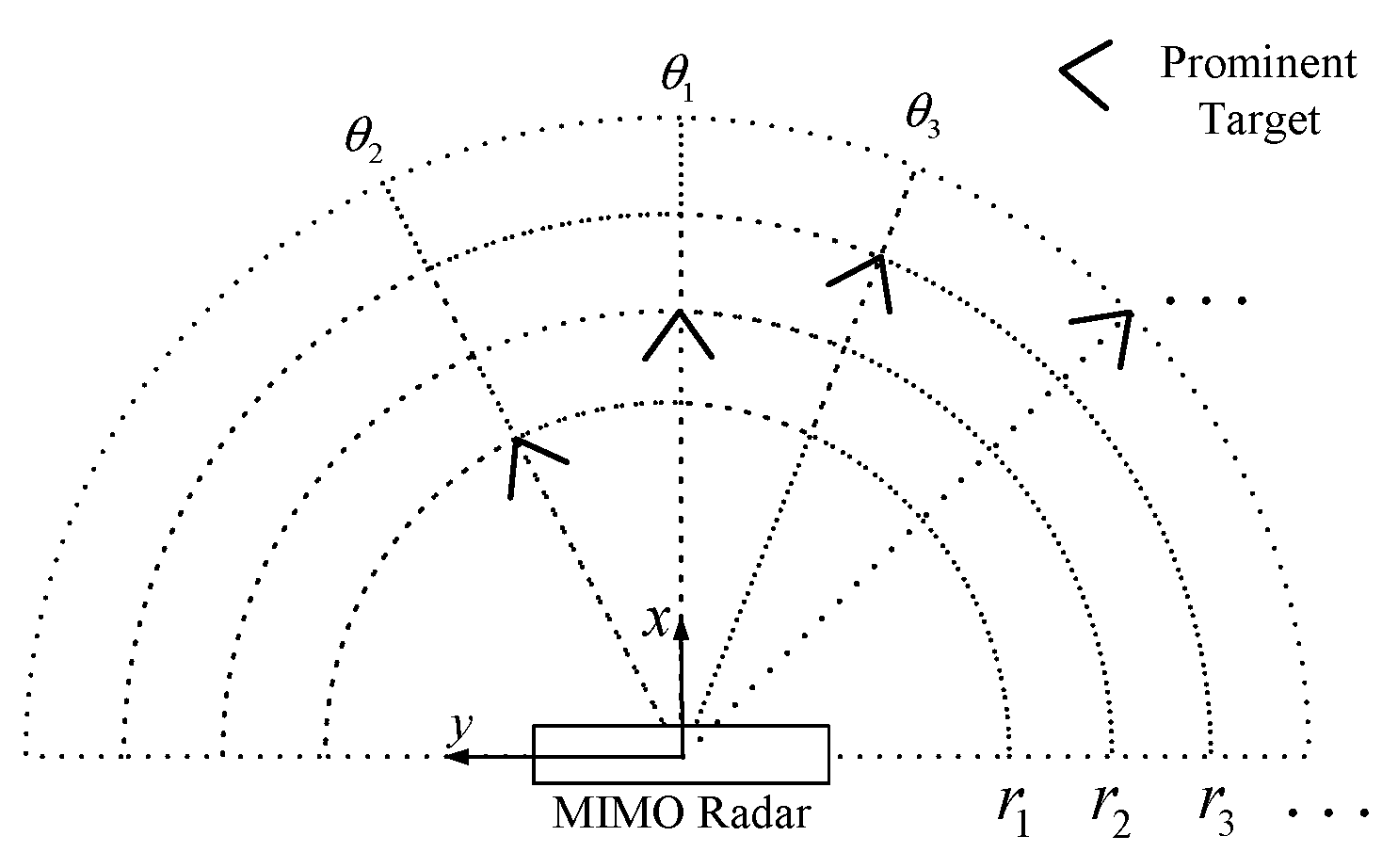
3.1. Position Estimation of Prominent Targets
3.2. Amplitude and Delay Error Estimation
3.2.1. Amplitude Error Estimation
3.2.2. Delay Error Estimation
3.3. Estimation of Element Position Errors
4. Simulation and Experiment
4.1. Simulation Analysis
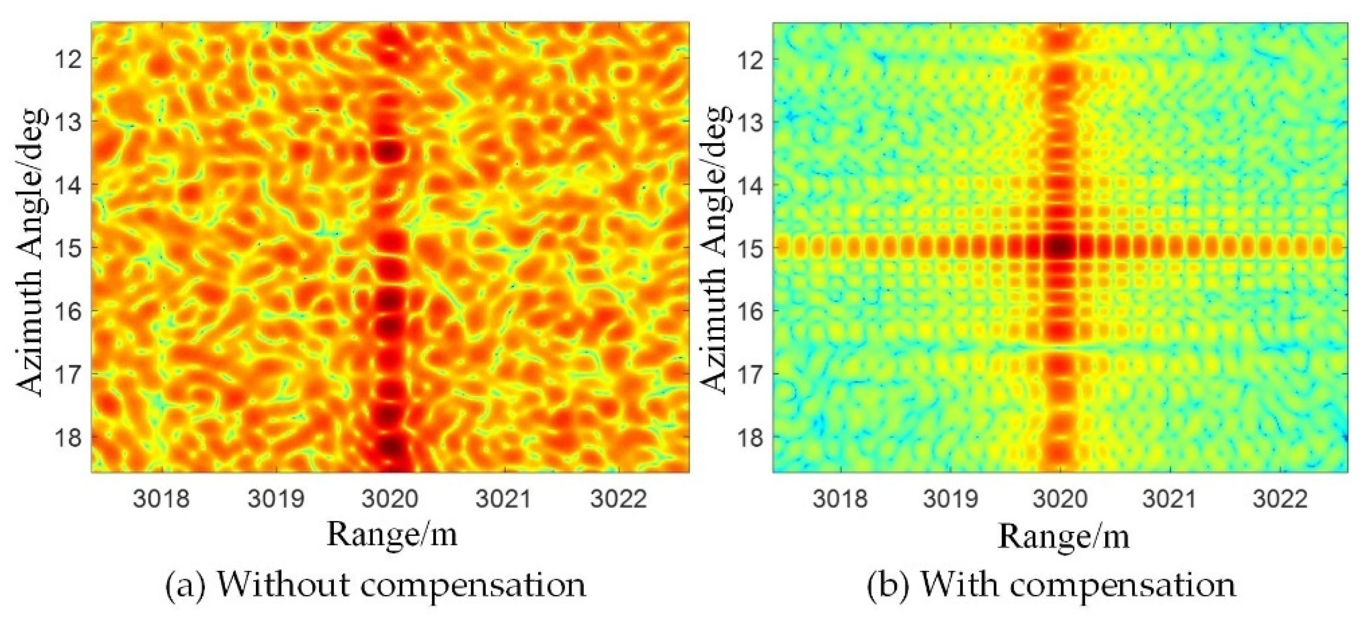
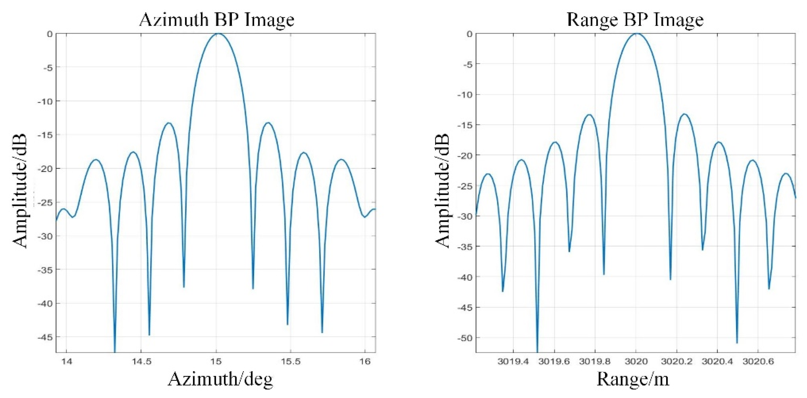
4.2. Experiment Analysis
5. Discussion
6. Conclusions
Author Contributions
Funding
Institutional Review Board Statement
Informed Consent Statement
Conflicts of Interest
References
- Pieraccini, M.; Miccinesi, L. Ground-based radar interferometry: A bibliographic review. Remote Sens. 2019, 11, 1029. [Google Scholar] [CrossRef] [Green Version]
- Hu, C.; Zhu, M. High-Precision deformation monitoring algorithm for GBSAR system: Rail de-termination phase error compensation. Sci. China Inf. Sci. 2015, 58, 082307. [Google Scholar] [CrossRef] [Green Version]
- Tian, W.; Li, Y. Vibration Measurement Method for Artificial Structure Based on MIMO Imaging Radar. IEEE Trans. Aerosp. Electron. Syst. 2020, 56, 748–760. [Google Scholar] [CrossRef]
- Deng, Y.; Hu, C. A Grid Partition Method for Atmospheric Phase Compensation in GB-SAR. IEEE Trans. Geosci. Remote Sens. 2021, 1–13. [Google Scholar] [CrossRef]
- Tarchi, D.; Oliveri, F. MIMO Radar and Ground-Based SAR Imaging Systems: Equivalent Approaches for Remote Sensing. IEEE Trans. Geosci. Remote Sens. 2013, 51, 425–435. [Google Scholar] [CrossRef]
- Wang, H. MIMO Radar Imaging Algorithms; National University of Defence Technology: Changsha, China, 2010. [Google Scholar]
- Jia, Y.; Bao, Z. A new calibration technique with signal sources for position, gain and phase uncertainty of sensor array. Acta Electron. Sin. 1996, 24, 47–52. [Google Scholar]
- Sheng, G.; Wang, H. Fast Angle Estimation and Sensor Self-Calibration in Bistatic MIMO Radar with Gain-Phase Errors and Spatially Colored Noise. IEEE Access 2020, 8, 123701–123710. [Google Scholar] [CrossRef]
- Xu, X.; Zhou, X. Radar coincidence imaging with array position error. In Proceedings of the IEEE International Conference on Signal Processing, Communications and Computing (ICSPCC), Ningbo, China, 19–22 September 2015; Institute of Electrical and Electronics Engineers: Piscataway, NJ, USA, 2015; pp. 1–4. [Google Scholar]
- Yang, J.; Huang, X. Compressed Sensing Radar Imaging with Compensation of Observation Position Error. IEEE Trans. Geosci. Remote Sens. 2014, 52, 4608–4620. [Google Scholar] [CrossRef]
- Gumbmann, F.; Schmidt, L.P. Millimeter-Wave Imaging with Optimized Sparse Periodic Array for Short-Range Applications. IEEE Trans. Geosci. Remote Sens. 2011, 49, 3629–3638. [Google Scholar] [CrossRef]
- Solomon, I.; Gray, D. Receiver Array Calibration Using Disparate Sources. IEEE Trans. Antennas Propag. 1999, 47, 496–505. [Google Scholar] [CrossRef]
- Liu, C.; Yan, J. Sparse self-calibration by map method for MIMO radar imaging. In Proceedings of the IEEE International Conference on Acoustics, Speech and Signal Processing (ICASSP), Kyoto, Japan, 25–30 March 2012; Institute of Electrical and Electronics Engineers: Piscataway, NJ, USA, 2012; pp. 2469–2472. [Google Scholar]
- Sammartin, P.; Tarchi, D. Phase compensation and processing in multiple-input–multiple-output radars. IET Radar Sonar Navig. 2012, 6, 222–232. [Google Scholar] [CrossRef]
- Ma, Z.; Liu, Y. Sparse recovery-based space-time adaptive processing with array error self-calibration. Electron. Lett. 2014, 50, 952–954. [Google Scholar] [CrossRef]
- Kim, J.; Yang, H. Blind Calibration for a Linear Array with Gain and Phase Error Using Independent Component Analysis. IEEE Antennas Wirel. Propag. Lett. 2010, 9, 1259–1262. [Google Scholar] [CrossRef]
- Wylie, M.; Roy, S. Joint DOA estimation and phase calibration of linear equispaced (LES) arrays. IEEE Trans. Signal Process. 1994, 42, 3449–3459. [Google Scholar] [CrossRef]
- Huo, R.; Tian, W. A compensation method of multiple-channel amplitude and phase errors for MIMO imaging radar. J. Eng. 2019, 19, 5901–5904. [Google Scholar] [CrossRef]
- Schmid, C.; Pfeffer, C. An FMCW MIMO radar calibration and mutual coupling compensation approach. In Proceedings of the 2013 European Radar Conference, Nuremberg, Germany, 9–11 October 2013; Institute of Electrical and Electronics Engineers: Piscataway, NJ, USA, 2013; pp. 13–16. [Google Scholar]
- Liu, Y.; Xu, X. MIMO Radar Calibration and Imagery for Near-Field Scattering Diagnosis. IEEE Trans. Aerosp. Electron. Syst. 2018, 54, 442–452. [Google Scholar] [CrossRef]
- Zeng, T.; Mao, C. Ground-based SAR wide view angle full field imaging algorithm based on keystone formatting. IEEE JSTARS 2016, 9, 2160–2170. [Google Scholar] [CrossRef]
- Hu, C.; Wang, J. Generalized Ambiguity Function Properties of Ground-Based Wideband MIMO Imaging Radar. IEEE Trans. Aerosp. Electron. Syst. 2019, 55, 578–591. [Google Scholar] [CrossRef]
- Hu, C.; Wang, J. Design and Imaging of Ground-Based Multiple-Input Multiple-Output Synthetic Aperture Radar with Non-Collinear Arrays. Sensors 2017, 17, 598. [Google Scholar] [CrossRef] [PubMed]
- Wei, M. Theory and Calculation of Generalized Least Squares Problem; Science Press: Beijing, China, 2006. [Google Scholar]
- Koza, J. Genetic Programming; MIT Press: Cambridge, MA, USA, 1992. [Google Scholar]
- Zeng, T.; Wang, R. SAR image autofocus utilizing minimum-entropy criterion. IEEE GRSL 2013, 10, 1552–1556. [Google Scholar] [CrossRef]


| Parameter | Value | Parameter | Value |
|---|---|---|---|
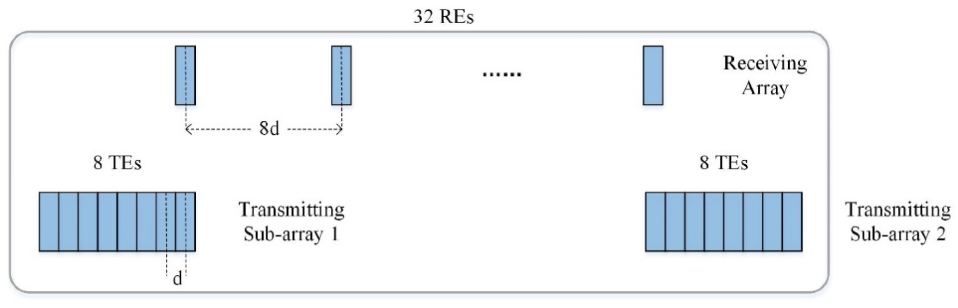
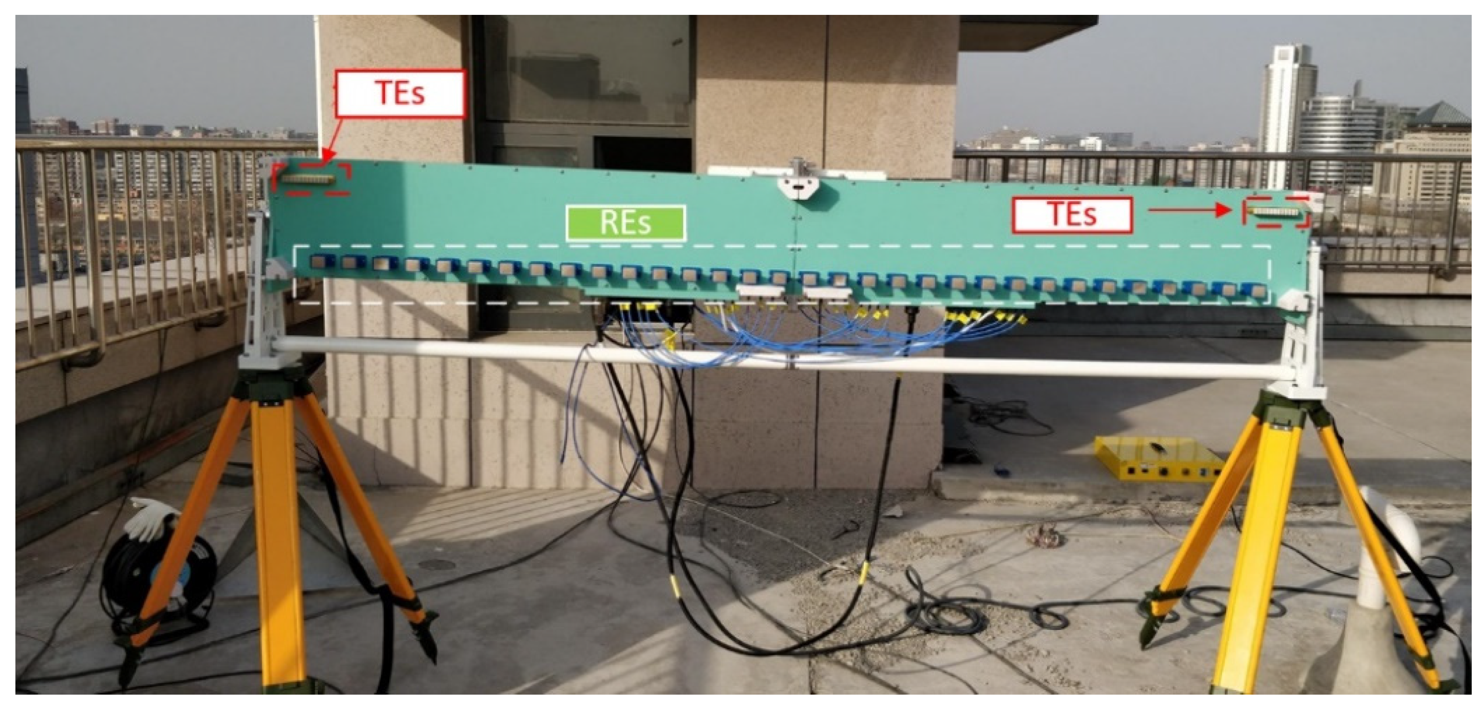
| Central Freq. | 16.2 GHz | TEs Num. | 16 |
| Pulse Width | 0.5 ms | REs Num. | 32 |
| Bandwidth | 1 GHz | TEs interval | 9.3 mm |
| Sample rate | 100 MHz 1 | REs interval | 74.4 mm |
| Index | Range/m | Azimuth/deg |
|---|---|---|
| T1 | 2990 | −30 |
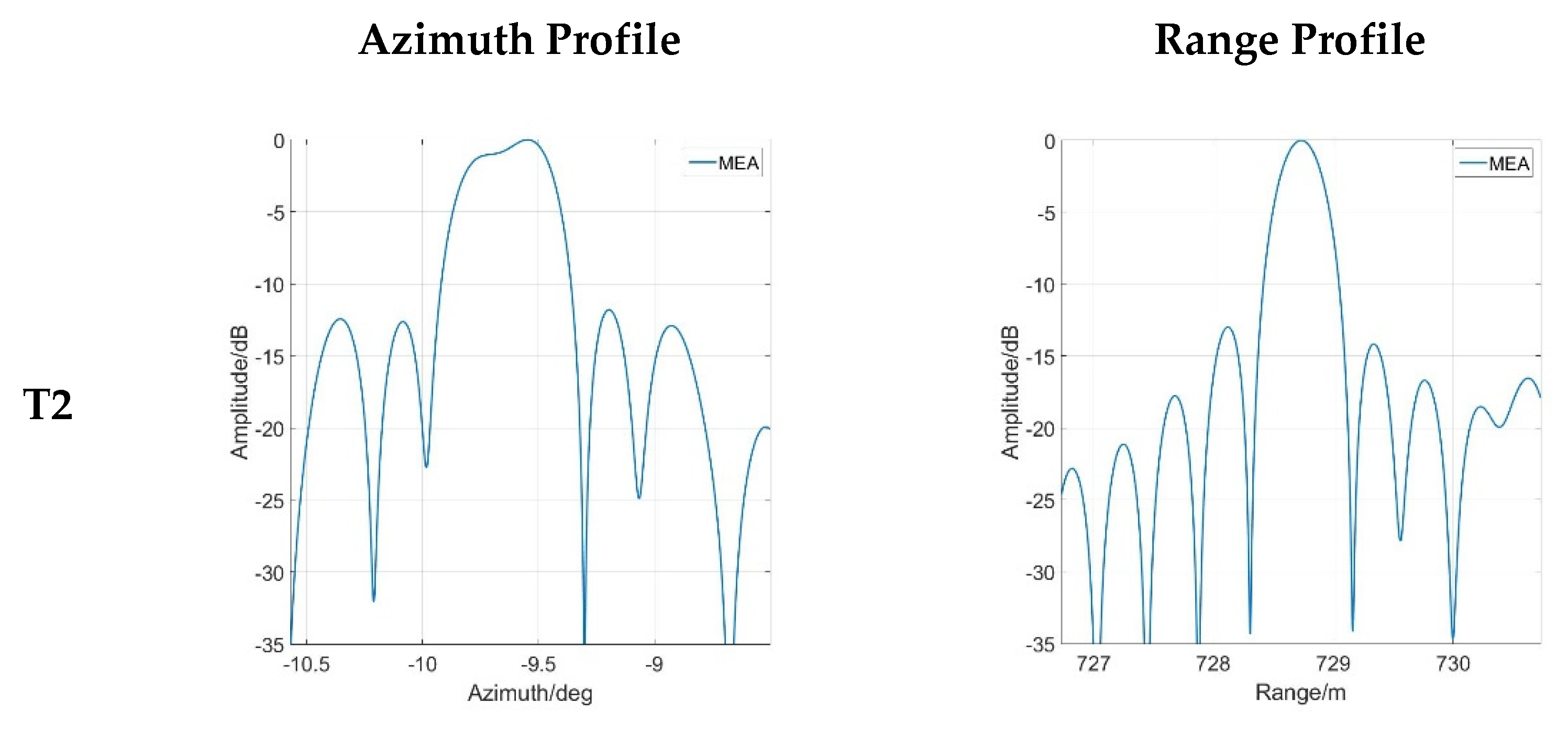
| T2 | 3000 | 0 |
| T3 | 3010 | 30 |
| T4 | 3020 | 15 |
| Parameter | Value | Parameter | Value |
|---|---|---|---|
| Central Freq. | 16.2 GHz | TEs Num. | 16 |
| Pulse Width | 2 ms | REs Num. | 32 |
| Bandwidth | 400 MHz | TEs interval | 9.3 mm |
| Sample rate | 12.5 MHz | REs interval | 74.4 mm |
| SPM | MPM | MEA | |
|---|---|---|---|
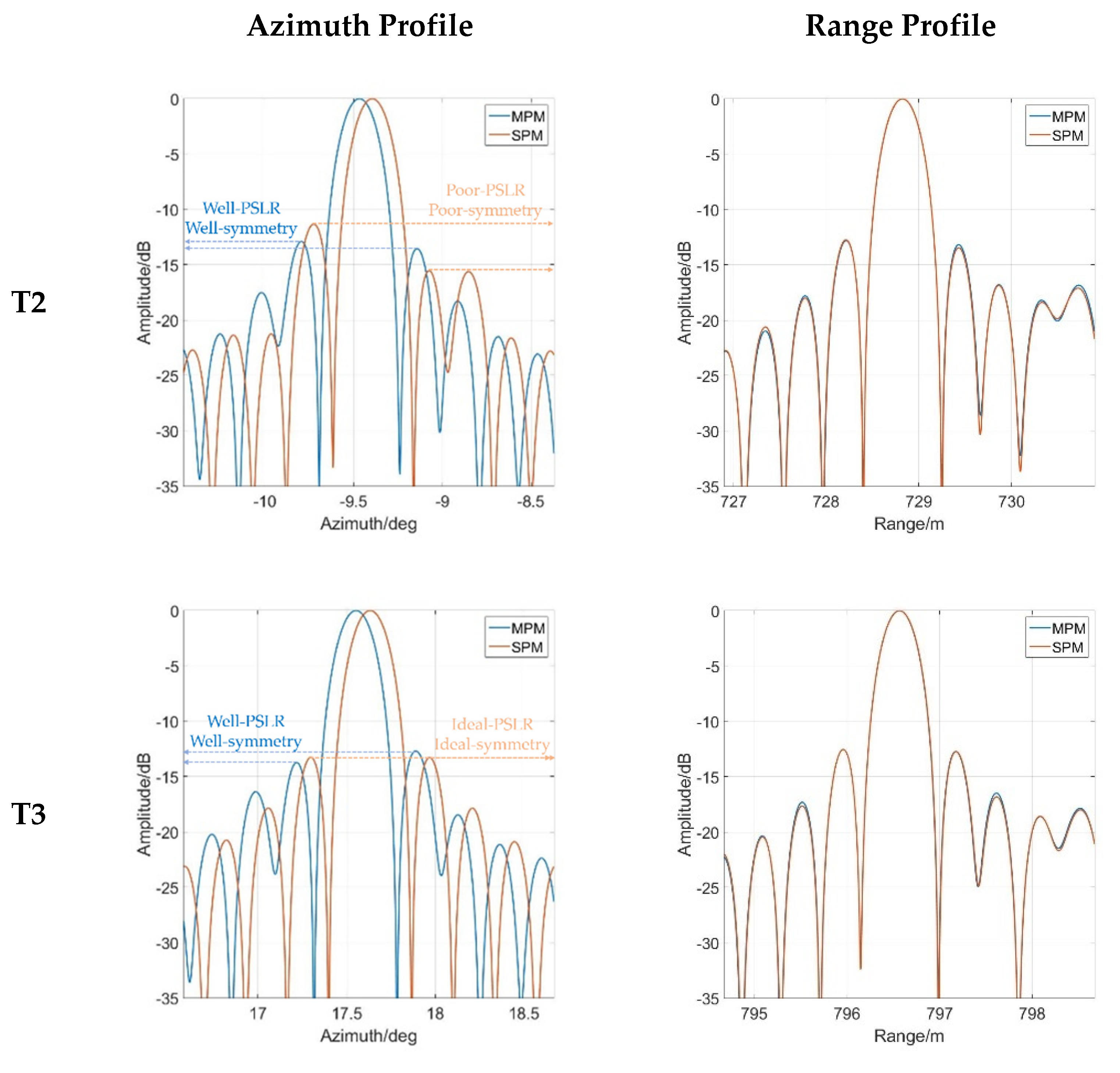
| Azimuth PSLR | −11.33 dB | −12.99 dB | −11.80 dB |
| Image Entropy | 11.80 | 11.77 | 11.95 (Ori. 13.13) |
| Calibration Time | 20 s | 10 min | >5 h |
| Pros. | Easy & Fast | Spatial-variant Elimination | Without Reference |
Publisher’s Note: MDPI stays neutral with regard to jurisdictional claims in published maps and institutional affiliations. |
© 2021 by the authors. Licensee MDPI, Basel, Switzerland. This article is an open access article distributed under the terms and conditions of the Creative Commons Attribution (CC BY) license (https://creativecommons.org/licenses/by/4.0/).
Share and Cite
Zhao, Z.; Tian, W.; Deng, Y.; Hu, C.; Zeng, T. Calibration Method of Array Errors for Wideband MIMO Imaging Radar Based on Multiple Prominent Targets. Remote Sens. 2021, 13, 2997. https://doi.org/10.3390/rs13152997
Zhao Z, Tian W, Deng Y, Hu C, Zeng T. Calibration Method of Array Errors for Wideband MIMO Imaging Radar Based on Multiple Prominent Targets. Remote Sensing. 2021; 13(15):2997. https://doi.org/10.3390/rs13152997
Chicago/Turabian StyleZhao, Zheng, Weiming Tian, Yunkai Deng, Cheng Hu, and Tao Zeng. 2021. "Calibration Method of Array Errors for Wideband MIMO Imaging Radar Based on Multiple Prominent Targets" Remote Sensing 13, no. 15: 2997. https://doi.org/10.3390/rs13152997
APA StyleZhao, Z., Tian, W., Deng, Y., Hu, C., & Zeng, T. (2021). Calibration Method of Array Errors for Wideband MIMO Imaging Radar Based on Multiple Prominent Targets. Remote Sensing, 13(15), 2997. https://doi.org/10.3390/rs13152997