Abstract
Antenna is one of the key payloads of the GNSS-R system, and the gain is an important performance parameter. The signal-to-noise ratio (SNR) of the received signal can be improved by increasing the gain of the GNSS-R antenna, therefore the measurement accuracy is improved. However, the antenna gain and its beam width, these two performance parameters, are contradictory. If the gain of the antenna is increased, its beam width will inevitably become narrower. This narrowed beam width will affect the width of the survey strip for the GNSS-R system, which cannot meet the requirement of the high-precision and high-spatial resolution spaceborne GNSS-R sea surface altimetry in the future. In this paper, a novel dual circularly polarized phased array antenna (NDCPPA) is proposed and investigated. First, the GNSS-R satellites currently operating in orbit are all cGNSS-R systems, which use the traditional element antenna (TEA) method for measurement. The antenna used in this method is with low gain, which limits the improvement of sea surface measurement accuracy. In response to this problem, this paper establishes an NDCPPA model of iGNSS-R measurement system based on the theory of coherent signal processing on the sea surface. This model uses the high-gain scanning beam to increase the gain of the iGNSS-R antenna without affecting its coverage area, thereby improving the sea surface altimetry precision. Second, in order to verify the gain improvement effect brought by adopting the NDCPPA model, an NDCPPA model verification prototype for iGNSS-R sea surface altimetry was designed and fabricated, and then measured in a microwave anechoic chamber. The measurement results show that, compared with the TEA method, the antenna gain of our proposed verification prototype is enhanced by 9.5 dB. And the measured and designed value of the gain of the verification prototype matches well. Third, based on the GPS L1 signal, the NDCPPA model is used to analyze the effect of improving the precision of sea surface altimetry. Compared with the TEA method, the proposed model can increase the altimetric precision of the nadir point from 7.27 m to 0.21 m, which effectively improves the performance of the iGNSS-R altimetry. The NDCPPA model proposed in this article can provide the theoretical method basis and the crucial technical support for the future high-precision and high-spatial-resolution GNSS-R sea surface altimetry verification satellite.
1. Introduction
As a novel remote sensing technology by microwave, there are many advantages of the global navigation satellite system reflectometry (GNSS-R), such as the plentiful amount of signal sources available, low cost, low power consumption, and ability to be measured at all times and all-weather [1,2]. In 1993, the passive reflectometry and interferometric system (PARIS) [3] was first proposed by Martin-Neira. From then, a large number of theoretical and experimental studies have verified the feasibility of GNSS-R measurement technology. Katzberg et al. (2005) and Carreno-Luengo et al. (2015) conducted GNSS-R research on airborne platforms and obtained corresponding remote sensing information [4,5]. Beyerle et al. (2001, 2002), Lowe et al. (2002), and Gleason et al. (2005), successively detected GPS reflection signals in the Low Earth Orbit (LEO) platform, which further verified the spaceborne GNSS-R feasibility [6,7,8,9]. In recent years, sea surface altimetry has become a hotspot of GNSS-R research. In 1997 and 2002, Martin-Neira successively proposed the theory and method of using a GNSS-R code phase and carrier phase for sea surface altimetry [10,11]. In 2011, Martin-Neira et al. proposed the GNSS-R carrier interferometric altimetry technology, which proved that obtained sea surface height information is suitable for mesoscale ocean observation technology [12]. In 2011, Semmling and Larson successively used GNSS-R observation data to measure the sea surface height [13,14]. At present, the feasibility of GNSS-R sea surface altimetry technology has been verified, and the key to its application is improving its precision. The high-precision GNSS-R sea surface altimetry data can effectively promote the accuracy of its inverted ocean physical model, which is the vital factor for the refined research of ocean motion [15]. In recent years, prospective research of theoretical methods and key technologies on the acquisition of high-precision ocean gravity field was conducted based on spaceborne GNSS-R measurement methods to improve the accuracy of underwater gravity matching navigation [16,17,18]. One of the key technologies among these studies was obtaining high-precision sea surface height based on the spaceborne GNSS-R technology.
According to different signal processing methods to obtain the delay, GNSS-R code altimetry mainly includes conventional GNSS-R (cGNSS-R) [19] and interferometric GNSS-R (iGNSS-R) [3]. All of the current in-orbit GNSS-R satellites are conducted with cGNSS-R technology and adopt the TEA method corresponding to this technology. The reflected signal is compensated by Doppler shift with the locally generated transmission signal copy (only C/A code) having a time delay after a certain time (typically 1 ms) of correlation. For cGNSS-R technology, as the low-gain antenna adopted by the TEA method, the SNR of the received signal is low. Moreover, the bandwidth of the C/A code (2.046 MHz) is relatively narrow. These two factors limit the cGNSS-R altimetric performance. Tasks using the cGNSS-R technology include: United Kingdom Disaster Monitoring Constellation (UK-DMC) [20], TechDemoSat-1 (TDS-1) [21], 3Cat-2 [22], Cyclone Global Navigation Satellite System (CYGNSS) [23], and Catching Wind No.1 Constellation [24]. However, since the above satellite missions are not designed for sea surface altimetry, the error of using TDS-1 and CYGNSS to measure sea surface height is more than 2.5 m (1 Hz) [25,26], which is difficult to meet the centimeter-level requirements of inverting high-precision ocean gravity field to sea surface height. In order to conquer the limitation mentioned above on the altimetric precision, Martin-Neira et al. successively proposed the concept of the iGNSS-R and its related models [3,14]. The iGNSS-R does not need to understand the structure of the GNSS code, and directly correlates the reflected signal with the direct signal to obtain the time delay information. Therefore, the iGNSS-R technology can extract all the spectral components in the GNSS transmitted signal, which can improve the clarity of the autocorrelation function, and thus improve the measurement precision [27]. The altimetric performance of the iGNSS-R is proportional to the SNR. As the direct signal is correlated with the reflected signal and the wider signal bandwidth will bring higher thermal noise, it is necessary to use a higher gain direct and reflected signal receiving antenna to improve SNR. Compared with the cGNSS-R, the iGNSS-R can effectively promote the altimetric precision. Until now, there is no iGNSS-R satellite operating in orbit, and the key to realize this technology is the phased array antenna. For this purpose, research on the NDCPPA model is continued in this paper for iGNSS-R technology.
The typical model of the spaceborne cGNSS-R system and the iGNSS-R system is shown in Figure 1. For the cGNSS-R system, its receiver only receives the reflected GNSS signals; while for the iGNSS-R system, its receiver receives both the GNSS direct signal and the reflected signal from the sea surface at the same time, and measures the altitude by integrating the direct signal and the reflected signal. The polarization of the direct signal and reflected signal are right-hand circularly polarization (RHCP) and left-hand circularly polarization (LHCP), respectively. Two antennas are generally mounted on the GNSS-R receiver: one for RHCP to measure the direct signal and another for LHCP to measure the reflected signals [28,29]. Therefore, it is necessary to conduct research on dual circularly polarized GNSS-R phased array antennas.
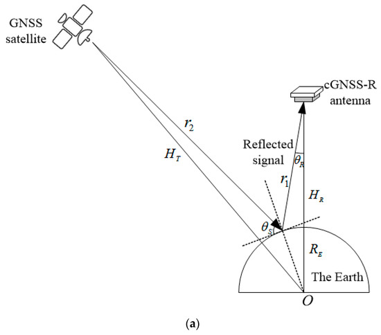
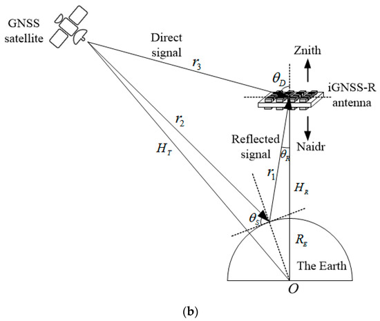
Figure 1.
The basic structure and geometric relationship of the (a) cGNSS-R system and (b) iGNSS-R system, where indicates the Earth’s core, indicates the elevation angle, indicates the Earth radius, and indicates the orbital height of the transmit and receive antenna, respectively, indicates the distance between the specular point and the GNSS-R antenna, indicates the distance between the GNSS satellite and the specular point, and indicates the distance between the GNSS satellite and the GNSS-R antenna.
However, the current dual-polarized antennas are mainly dual linear polarization performance [29,30,31], rather than dual circular polarization. Although these linear antennas can receive direct and reflected circularly polarized signals from GNSS satellites, there is a 3 dB polarization mismatch loss, which affects further improvement of the system SNR. Zhou et al. (2006, 2007) and Popugaev et al. (2007) proposed stacked patch antennas that work in mono circular polarization [28,29,30]. Although this circularly polarized antenna is used to receive direct and reflected circular GNSS satellites without polarization mismatch loss, they cannot be matched with the direct and reflected signals of RHCP and LHCP polarization modes at the same time. The dual-polarized antenna proposed by Jia et al. (2016, 2017) cannot achieve the same miniaturization and lightweight performance as the patch antenna [32,33]. In order to improve the performance of the GNSS-R altimetry, this paper uses a dual circularly polarized antenna to receive the direct and reflected signal. In addition, in order to reduce the cost and scale of GNSS-R systems, especially the airborne and spaceborne GNSS-R altimetry antennas, this paper designs an NDCPPA.
According to Figure 1, the power of the GNSS reflected signal is weak, and this performance limits the measurement precision of the iGNSS-R. As the measurement precision of the iGNSS-R is related to SNR, the correlation with direct signal and reflected signal will bring more thermal noise; thus, it is necessary to use a higher gain direct and reflected signal receiving antenna to improve SNR. However, there is a natural contradiction between high gain and wide beam, which makes the instantaneous coverage area of the high-gain antenna smaller than that of the low-gain antenna. Fortunately, the phased array antenna with scanning performance can simultaneously meet the requirements of the GNSS-R sea surface altimetry for high gain and wide coverage. Therefore, the GNSS-R sea surface altimetry needs a high-gain antenna with beam scanning performance to improve SNR without affecting its coverage area, thereby improving the measurement precision.
Differing from previous studies, this paper establishes an NDCPPA model of the iGNSS-R altimeter based on the theory of coherent signal processing of the sea surface. This model adopts a novel dual circular polarized phased array antenna to generate a high-gain beam with scanning performance. Compared with the TEA method, the novel dual circular polarized phased array antenna model proposed in this paper effectively improves the sea surface altimetric precision without affecting its coverage, with a view to provide antenna design theoretical methods and crucial technical support for the high-precision and high-spatial resolution GNSS-R sea surface altimetry verification satellite in the future.
2. Construction of the NDCPPA Model
Given the satellite’s incident signal (RHCP), from the bi-static radar equation, the scattered coherent power by the sea surface is given by [34]:
where is the power of the GNSS satellite’s transmitting signal, and are the gain values of GNSS satellite’s transmitting antenna and that of GNSS-R satellite’s receiving antenna, respectively, is the wavelength of GPS L1 signal ( = 19.042 cm), is the length of the signal chain from the sea surface specular point to the GNSS-R satellite’s nadir receiving antenna, is the length of the signal chain from the GNSS satellite’s transmitting antenna to the sea surface specular point, is the length of the signal chain from the GNSS satellite’s transmitting antenna to the GNSS-R satellite’s zenith receiving antenna, and is the power reflectivity, which is determined as [35]:
where is the probability density function at altitude , which depends on the surface roughness. For this paper, we assume that the sea surface is a perfectly flat surface, and equals 1 for this condition, and is the Fresnel reflection coefficient.
The geometric relationship between the elements of the iGNSS-R system is marked in Figure 1b. Where and which are the elevation angles of the GNSS-R satellite’s nadir antenna relative to the specular reflection point and that of the zenith antenna relative to the GNSS satellite, respectively. When calculating SNR at the specular reflection point, the value of and can be determined by , which is GNSS satellite’s elevation angle at the sea surface specular reflection point [36]:
where is the radius of the Earth, and are the orbital height of the GNSS satellite and the GNSS-R satellite, respectively. In addition, , , and can be obtained by [36]:
Combining Equations (1) and (2), the processed SNR of reflected signal can be written as [35]:
where is the noise power, is Boltzmann constant, is the equivalent noise temperature of the reflected signal receiving channel of the GNSS-R satellite, is the minimum value between band width of GNSS signal and receiver. The SNR of the direct signal is [29]:
where is the distance between transmitter and receiver. For direct signal in Equation (6) and reflected signal in Equation (5), the receiving antenna gain and the noise power are different.
According to Equations (5) and (6), the gain of the receiving antenna is proportional to SNR of the direct and reflected signal received by GNSS-R satellite. Therefore, the SNR of these signals can be promoted by increasing the gain of the GNSS-R zenith and nadir antenna. In the cGNSS-R system which adopting the TEA method, the element antenna’s aperture electric field components for and direction can be expressed as [37]:
where is the aperture size of the antenna applied by the TEA method, and is the radial and circumferential coordinate component within the aperture of the element antenna, respectively. is the Bessel function and is the first zero of . Moreover, [37]:
According to [37]:
The gain can be obtained as:
where is the aperture size of the element antenna, which value is equal to the diameter of the antenna’s radiator, is the wavelength of the antenna, and is the efficiency of the antenna. Substituting Equation (11) into Equations (5) and (6), the SNR model for cGNSS-R altimetry, which adopts the TEA method can be obtained as:
where is aperture diameter of nadir cGNSS-R element antenna.
Figure 2 shows the structure of the NDCPPA model adopted by iGNSS-R system, which is composed of multiple antenna elements distributed on a plane, and each antenna element is equipped with a phase shifter to change the phase of the signal fed on it. All the phase shifters are controlled by a beam controller. Therefore, the expected electric field distribution function within antenna aperture can be obtained by changing the phase relationship between antenna elements. As the phase relationship between antenna elements changes, the required antenna radiation pattern and beam orientation is obtained. Each unit of the phased array antenna is fed with equal amplitude, and its adjacent elements are fed with the same phase difference . Therefore, the radiation pattern of the NDCPPA can be expressed as [38]:
where is the radiation pattern of antenna element, its and components are determined by Equations (7) and (8). In addition, the specific values of the phase difference between adjacent antenna elements are as follows [38]:
where (,) is the beam orientation, which means that the electric field strength of is at maximum in the direction of this angle. The two-dimensional coordinates of each element of the NDCPPA are [38]:
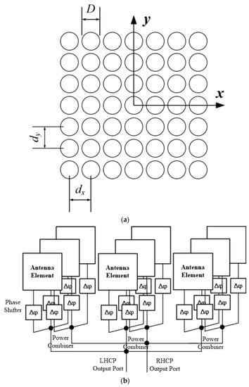
Figure 2.
Structure of the NDCPPA’s (a) element distribution and (b) circuit topology.
Substituting Equation (13) into Equation (10), the gain model of the NDCPPA can be obtained as:
Comparing Equations (11) and (17), the gain of the NDCPPA model is increased by dB compared with the TEA method. Thus, it is conducive to improving the SNR of the iGNSS-R system by adopting the NDCPPA model. Substituting Equation (17) into Equations (5) and (6), the NDCPPA model can be obtained as:
where and are element apertures of the zenith antenna and nadir antenna for the NDCPPA model, respectively. And and for the NDCPPA model, corresponding to the directed RHCP signal and reflected LHCP signal, respectively.
Comparing Equations (12) and (18) with the TEA method, as the gain increases, the SNR of the NDCPPA model increases by dB.
For the iGNSS-R altimetry technology, the uncertainty of altimetry is mainly reflected in the uncertainty of the waveform. And the main factor affecting the altimetric precision is the randomness of the received signal caused by thermal noise and speckle noise [26]. Among them, the influence of speckle noise can be reduced by a certain number of incoherent accumulations. The specific method is to directly cross-correlate the reflected signal with the direct signal to obtain the time delay information. When calculating the received SNR, additional considerations need to be given to the thermal noise of the reflected-signal receiving channel and the noise generated when direct and reflected signals are correlated [14]. Then the iGNSS-R SNR after cross-correlation with the direct signal and the reflected signal can be indicated as [14]:
Among them, and are the SNR of the GNSS satellite’s direct signal and the signal reflected by the sea surface before cross-correlation, respectively. Substituting the direct signal and reflected signal of the new dual circularly polarized phased array antenna model in Equation (18) into Equation (19), the iGNSS-R SNR model based on the NDCPPA model can be obtained:
In order to analyze the improvement effect of the NDCPPA model on the precision of iGNSS-R altimetry relative to the TEA method, based on the accuracy model provided in the article [14], the altimetric precision of the TEA method and the NDCPPA model is established:
Among them, is the average incoherent coefficient of the signal sample, and are the altitude measurement sensitivity of the TEA method and the NDCPPA model, which can be considered to depend on the autocorrelation characteristics of the signal in a spaceborne scene [39], and can be defined as . and are the mean powers at the specular reflection point () of the sea surface and the leading-edge derivative (DER) of the power waveform, is the light velocity. In addition, the elevation obtained in this paper is the WGS-84 elevation, that is, the elevation reference datum is the datum ellipsoid defined by WGS-84, while the orthometric reference datum is the geoid. By obtaining the distance between the WGS-84 datum ellipsoid and the geoid at a certain point difference, we can realize the conversion between WGS-84 height and ortho height.
3. Model Verification and Application of the NDCPPA
According to Equation (18), it can be known that the main factor of gain improvement by adopting the NDCPPA model is antenna elements M and N for two dimensions, respectively. In order to verify the NDCPPA model, we proposed a verification prototype of the NDCPPA model. The proposed NDCPPA model verification prototype was designed, manufactured, and measured. Then, the simulated and measured results of the NDCPPA model were compared.
In order to verify the effect of gain promotion by adopting the NDCPPA model, this paper designed an NDCPPA verification prototype for GNSS-R system. First, the NDCPPA’s element that matched the GPS L1 band of the iGNSS-R was designed, and then this NDCPPA’s element was used as the array element of the NDCPPA. Then, in order to verify the performances of the NDCPPA model, including the gain and the SNR performance, an NDCPPA model verification prototype was fabricated, and was measured in a microwave anechoic chamber using AgilentTM E8361A Network Analyzer. The verification and application of the proposed NDCPPA model is introduced in detail below.
3.1. Design of NDCPPA Model Verification Prototype
The structure of the NDCPPA model’s element is shown in Figure 3. The NDCPPA model’s element was based on the dielectric substrate, and the conductive radiating patch and the ground plate were attached on the front and back side of the dielectric substrate. The parameters of the NDCPPA model’s element are particularized in Table 1. As seen in Figure 3, the feed position at point resulted in RHCP radiation, while point was for LHCP radiation.
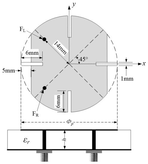
Figure 3.
Geometry of the NDCPPA model’s element.

Table 1.
Design parameters of the element of NDCPPA model verification prototype.
Figure 4 and Figure 5 show the main electrical properties of the NDCPPA model’s element. As shown in Figure 4, in the frequency band from 1.54 to 1.62 GHz, the reflection coefficient of the NDCPPA model’s element was better than −10 dB, which indicates its impedance bandwidth. Figure 5 shows the simulated radiation pattern and axial ratio of the NDCPPA model’s element. The bandwidth of 3 dB axial ratio with the NDCPPA model’s element was 61 MHz (1.54–1.61 GHz). Within this frequency bandwidth, the good impedance matching characteristic and circular polarization characteristic could be achieved. In Figure 4 and Figure 5, LHCP was the performance of the antenna array’s element fed by defined in Figure 3, and RHCP was the performance fed by .
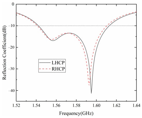
Figure 4.
Simulated reflection coefficient of the NDCPPA model’s element.
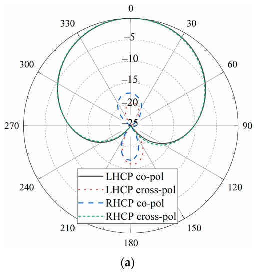
Figure 5.
The simulated (a) radiation pattern and (b) axial ratio of the NDCPPA model’s element.
The proposed NDCPPA model verification prototype was composed of 3 3 elements introduced above, and the element spacing was 100 mm (0.5 ). The overall volume of the 3 3 array was 300 mm 300 mm 2 mm (1.5 1.5 0.01). The configuration shown in Figure 2b consisted of positioning a phase shifter in front of the LHCP port and another phase shifter in front of the RHCP port of each antenna array’s element illustrated in Figure 3. As shown in Figure 2b, nine phase shifters and a two-stage 3-in-1 power combiner together formed a beam forming network for one polarization. Therefore, the proposed verification prototype had a set of LHCP and RHCP beam forming networks respectively, which could simultaneously form LHCP and RHCP beams. As for the beam mentioned above, each element was equipped with a phase shifter to control its fed-phase, thus the beam orientation of the NDCPPA could be shifted by tuning the phase shifters. The elements in the array were fed by currents with uniform amplitude and progressive phase shift , and the specific value of the phase difference was determined by Equation (14). For this paper, M = N = 3, and = = 100 mm.
According to the Equation (13), and the total radiated electric field was equal to the sum of the radiated electric fields of each feeding element. The linear gain value of NDCPPA model was times of its element, which could be converted into dB.
3.2. Verification of NDCPPA Model
After the design and fabrication, the NDCPPA model verification prototype was realized as shown in Figure 6 and was measured in an anechoic chamber. As mentioned above, the NDCPPA model verification prototype formed LHCP and RHCP beams simultaneously. The patterns of these two beams were the same shape, and the two beam forming networks were independent of each other. Therefore, manufacturing and measuring a mono-polarized beam was sufficient to verify the performance of the NDCPPA model verification prototype. Based on these considerations, this paper verifies the LHCP beam of the NDCPPA model verification prototype. In recent years, due to the wide application of printed antennas in GNSS precision technology [40,41], the cost of equipment in this field has been greatly reduced, and the equipment has been widely spread. The NDCPPA model verification prototype proposed in this paper used the same type of printed antenna; thus, it can also greatly reduce the cost of GNSS-R equipment, thereby speeding up the popularization of GNSS-R equipment.
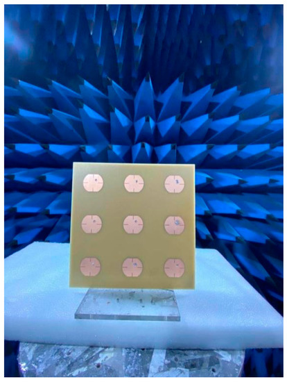
Figure 6.
NDCPPA model verification prototype.
The NDCPPA model verification prototype was measured in the anechoic chamber using the AgilentTM E8361A Network Analyzer. Figure 7 shows the measured scanning radiation patterns of the NDCPPA model verification prototype. The measured results show that the main beam scans from 0° to 40° within 1.3 dB peak gained fluctuation, which was acceptable for the iGNSS-R sea surface altimetry. Table 2 is the statistic of beam performance during scanning. The table shows that the beam scanning angle θ changed from 0° to 40°, the equivalent aperture of the antenna changes according to the cosθ rule, which is in line with the general phased array antenna law. Correspondingly, the gain decreased from 14.0 dB to 12.7 dB, and the beamwidth increased from 31° to 50°.
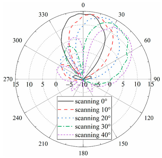
Figure 7.
Measured scanning radiation patterns of the NDCPPA model verification prototype.
Table 2.
Beam performances during scanning of the NDCPPA model verification prototype.
Figure 8 shows the comparison of the measurement gain between the novel dual circular polarization phased array model verification prototype and the traditional element antenna. The figure shows that the measured antenna peak gain was 4.5 dB for the TEA model, while the peak gain was 14.0 dB for the NDCPPA model verification prototype. Compared with the TEA method, antenna gain was promoted by 9.5 dB by adopting the NDCPPA model verification prototype. In addition, from Equations (5) and (6), as the gain of the zenith antenna and nadir antenna was promoted by 9.5 dB, the SNR of the direct and reflected signal of the iGNSS-R sea surface altimetry was also promoted by 9.5 dB.
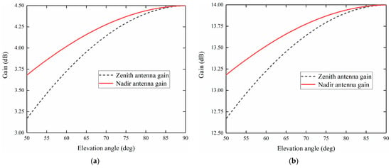
Figure 8.
(a) TEA and Comparison of measured gain between (b) NDCPPA model verification prototype.
3.3. Application of NDCPPA Model
In this study, the observation scenario of the TDS-1 satellite was used to evaluate the SNR of iGNSS-R. Therefore, the system parameters of the iGNSS-R altimeter were as consistent with TDS-1 as possible. The specific parameter settings are shown in Table 3. Figure 9 shows the calculated SNR when the NDCPPA model verification prototype was used as zenith antenna and nadir antenna. When calculating, use the simulated value and measured antenna gain into the simulation environment listed in Table 3 to obtain the comparison of SNR. According to Figure 9, the SNR calculated from the simulated and the measured gain in the simulated environment is in good agreement, and the difference between them is less than 0.1 dB.
Table 3.
Parameters of the simulation environment for SNR calculation.
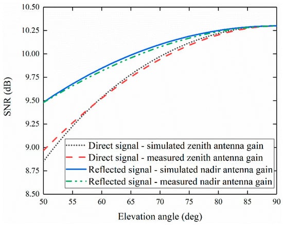
Figure 9.
SNR by adopting the NDCPPA verification prototype: the comparison of simulated antenna gain and measured antenna gain brought into the simulation environment.
Next, this study evaluated the altimetric precision of the NDCPPA model verification prototype applied in the spaceborne iGNSS-R sea surface altimetry scenario. Figure 10 shows the calculated altimetric precision when the NDCPPA model verification prototype was used as a zenith antenna and nadir antenna. When calculating, use the simulated and measured antenna gain into the simulation environment. According to Figure 10, due to the SNR calculated from the simulated and measured gain brought into the simulated environment in good agreement, the altimetric precision difference between the two situations is less than 0.01 m.
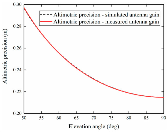
Figure 10.
Altimetric precision of the NDCPPA verification prototype: the comparison of simulated antenna gain and measured antenna gain brought into the simulation environment.
Figure 11 shows the comparison of the calculated altimetric precision of the NDCPPA model verification prototype and the TEA gain measured values used in the simulation environment. According to Figure 11, compared with the TEA method, the NDCPPA model verification prototype promotes the iGNSS-R’s nadir altimetric precision from 7.27 m to 0.21 m, thereby effectively improving the performance of the iGNSS-R altimetry.

Figure 11.
The altimetric precision improvement of the NDCPPA model verification prototype compared to the TEA method.
4. Conclusions
The antenna gain is an important indicator of the GNSS-R sea surface altimetry. By increasing the antenna gain, the SNR of the received signal can be improved, thereby improving the precision of the GNSS-R sea surface altimetry. The adoption of an NDCPPA model is an effective way to improve the antenna gain.
First, for the NDCPPA model, the increase of gain is proportional to its antenna elements number, which is dB. In addition, the overall coverage of the NDCPPS can be expanded by beam scanning.
Second, the NDCPPA model verification prototype in this paper adopts a 3 by 3 scale, and the gain is increased by 9.5 dB compared with the TEA method, which verifies the correctness of the theoretical model. The altimetric precision of the nadir point therefore enhances from 7.27 m to 0.21 m, correspondingly. For the actual projects, the gain of the NDCPPA can be further improved by increasing the elements number.
Third, the measurement results of the NDCPPA model verification prototype proposed in this paper show that the method can improve the antenna gain of GNSS-R satellites, thereby improving the iGNSS-R altimetric precision. The NDCPPA model proposed in this paper can provide a theoretical method basis and crucial technical support for the antenna design of the GNSS-R sea surface altimetry verification satellite with high precision and high spatial resolution in the future.
Author Contributions
Writing–original draft, Z.C.; Writing–review & editing, W.Z., F.W., X.L., C.Z., Z.L. and X.M. All authors have read and agreed to the published version of the manuscript.
Funding
This research was funded by the National Nature Science Foundation of China (41774014, 41574014), the Liaoning Revitalization Talents Program under grant (XLYC2002082), the Frontier Science and Technology Innovation Project and the Innovation Workstation Project of Science and Technology Commission of the Central Military Commission under grant (085015), and the Outstanding Youth Foundation of the China Academy of Space Technology, and the Independent Research and Development Start-up Fund of Qian Xuesen Laboratory of Space Technology (Y-KC-WY-99-ZY-000-025).
Institutional Review Board Statement
Not applicable.
Informed Consent Statement
Not applicable.
Data Availability Statement
Not applicable.
Acknowledgments
This work was supported by the National Nature Science Foundation of China (41774014, 41574014), the Liaoning Revitalization Talents Program under grant (XLYC2002082), the Frontier Science and Technology Innovation Project and the Innovation Workstation Project of Science and Technology Commission of the Central Military Commission under grant (085015), and the Outstanding Youth Foundation of the China Academy of Space Technology, and the Independent Research and Development Start-up Fund of Qian Xuesen Laboratory of Space Technology (Y-KC-WY-99-ZY-000-025). Zhen Cui, Wei Zheng and Fan Wu contributed equally to this paper.
Conflicts of Interest
The authors declare no conflict of interest.
References
- Jin, S.G.; Cardellach, E.; Xie, F. GNSS Remote Sensing, Theory, Methods and Applications; Springer Publishing Company, Incorporated: Heidelberg/Berlin, Germany, 2014. [Google Scholar]
- Rodriguez-Alvarez, N.; Camps, A.; Vall-llossera, M.; Bosch-Lluis, X.; Monerris, A.; Ramos-Perez, I.; Valencia, E.; Marchan-Hernandez, J.F.; Martinez-Fernandez, J.; Baroncini-Turricchia, G.; et al. Land geophysical parameters retrieval using the interference pattern GNSS-R technique. IEEE Trans. GEOsci. Remote Sens. 2011, 49, 71–84. [Google Scholar] [CrossRef]
- Martin-Neira, M. A Passive Reflectometry and Interferometry System (PARIS): Application to ocean altimetry. ESA J. 1993, 17, 331–355. [Google Scholar]
- Katzberg, S.J.; Torres, O.; Grant, M.S.; Masters, D. Utilizing calibrated GPS reflected signals to estimate soil reflectivity and dielectric constant: Results from SMEX02. Remote Sens. Environ. 2006, 100, 17–28. [Google Scholar] [CrossRef] [Green Version]
- Carreno-Luengo, H.; Amezaga, A.; Vidal, D.; Olive, R.; Munoz, J.F.; Camps, A. First polarimetric GNSS-R measurements from a stratospheric flight over Boreal forests. Remote Sens. 2015, 7, 13120–13138. [Google Scholar] [CrossRef] [Green Version]
- Beyerle, G.; Hocke, K. Observation and simulation of direct and reflected GPS signals in radio occultation experiment. Geophys. Res. Lett. 2001, 28, 1895–1898. [Google Scholar] [CrossRef]
- Beyerle, G.; Hocke, K.; Wickert, J.; Schmidt, T.; Marquardt, C.; Reigber, C. GPS radio occultations with CHAMP: A radio holographic analysis of GPS signal propagation in the troposphere and surface reflections. J. Geophys. Res. Atmos. 2002, 107, 1–14. [Google Scholar] [CrossRef] [Green Version]
- Lowe, S.T.; LaBrecque, J.L.; Zuffada, C.; Romans, L.J.; Young, L.E.; Hajj, G.A. First spaceborne observation of an earth-reflected GPS signal. Radio Sci. 2002, 37, 7-1–7-28. [Google Scholar] [CrossRef]
- Gleason, S.; Hodgart, S.; Sun, Y.; Gommenginger, C.; Mackin, S.; Adjrad, M.; Unwin, M. Detection and processing of bistatically reflected GPS signals from low earth orbit for the purpose of ocean remote sensing. IEEE Trans. Geosci. Remote Sens. 2005, 43, 1229–1241. [Google Scholar] [CrossRef] [Green Version]
- Martín-Neira, M.; Caparrini, M.; Font-Rossello, J.; Lannelongue, S.; Vallmitjana, C.S. The PARIS concept: An experimental demonstration of sea surface altimetry using GPS reflected signals. IEEE Trans. Geosci. Remote Sens. 2001, 39, 142–150. [Google Scholar] [CrossRef] [Green Version]
- Martín-Neira, M.; Colmenarejo, P.; Ruffini, G.; Serra, C. Altimetry precision of 1 cm over a pond using the wide-lane carrier phase of GPS reflected signals. Can. J. Remote Sens. 2002, 28, 394–403. [Google Scholar] [CrossRef]
- Martín-Neira, M.; Addio, S.D.; Buck, C.; Floury, N.; Prieto-Cerdeira, R. The PARIS ocean altimeter in-orbit demonstrator. IEEE Trans. Geosci. Remote Sens. 2011, 49, 2209–2237. [Google Scholar] [CrossRef]
- Semmling, A.M.; Beyerle, G.; Stosius, R.; Dick, G.; Wickert, J.; Fabra, F. Detection of Arctic Ocean tides using interferometric GNSS-R signals. Geophys. Res. Lett. 2011, 38, 155–170. [Google Scholar] [CrossRef] [Green Version]
- Johan, L.; Rüdiger, H. The GPS tide gauge problem revisited. In Proceedings of the American Geophysical Union Fall Meeting, San Francisco, CA, USA, 5–9 December 2011. [Google Scholar]
- Zheng, W.; Xu, H.; Zhong, M.; Yun, M. Improvement in the recovery accuracy of the lunar gravity field based on the future Moon-ILRS spacecraft gravity mission. Surv. Geophys. 2015, 36, 587–619. [Google Scholar] [CrossRef]
- Wu, F.; Zheng, W.; Li, Z.; Liu, Z. Improving the GNSS-R specular reflection point positioning accuracy using the gravity field normal projection reflection reference surface combination correction method. Remote Sens. 2019, 11, 33. [Google Scholar] [CrossRef] [Green Version]
- Wu, F.; Zheng, W.; Li, Z.; Liu, Z. Improving the positioning accuracy of satellite-borne GNSS-R specular reflection point on sea surface based on the ocean tidal time-varying elevation correction positioning method. Remote Sens. 2019, 11, 1626. [Google Scholar] [CrossRef] [Green Version]
- Liu, Z.Q.; Zheng, W.; Wu, F.; Kang, G.H.; Li, Z.W.; Wang, Q.Q.; Cui, Z. Improving the number of sea surface altimetry reflected signals received by GNSS-R satellite based on the new satellite-borne nadia antenna receiving signal-to-noise ratio model. Remote Sens. 2019, 11, 2473-1–2473-16. [Google Scholar]
- Zavorotny, V.; Gleason, S.; Cardellach, E.; Camps, A. Tutorial on Remote Sensing Using GNSS Bistatic Radar of Opportunity. IEEE Geosci. Remote Sens. Lett. 2014, 2, 8–45. [Google Scholar] [CrossRef] [Green Version]
- Unwin, M.J.; Gleason, S.; Brennan, M. The space GPS reflectometry experiment on the UK disaster monitoring constellation satellite. In Proceedings of the ION-GPS/GNSS, Portland, OR, USA, 1 January 2003. [Google Scholar]
- Jales, P.; Unwin, M. MERRByS Product Manual—GNSS Reflectometry on TDS-1 with the SGR-ReSI; Surrey Satellite Technology Ltd.: Guilford, UK, 2017; Available online: http://www.merrbys.co.uk (accessed on 14 July 2017).
- Carreno-Luengo, H.; Camps, A.; Via, P.; Munoz, J.F.; Cortiella, A.; Vidal, D.; Jané, J.; Catarino, N.; Hagenfeldt, M.; Palomo, P. 3Cat-2—An Experimental Nanosatellite for GNSS-R Earth Observation: Mission Concept and Analysis. IEEE J. Sel. Top. Appl. Earth Obs. Remote Sens. 2016, 9, 4540–4551. [Google Scholar] [CrossRef] [Green Version]
- Ruf, C.; Chang, P.; Clarizia, M.P.; Gleason, S.; Jelenak, Z.; Murray, J.; Morris, M.; Musko, S.; Posselt, D.; Provost, D.; et al. CYGNSS Handbook; Michigan Publishing: Ann Arbor, MI, USA, 2016. [Google Scholar]
- Han, W.W. China Successfully Launches Fengfeng-1 A/B Satellite. Available online: https://china.huanqiu.com/article/9CaKrnKkO1r (accessed on 12 July 2019).
- Clarizia, M.P.; Ruf, C.; Cipollini, P.; Zuffada, C. First spaceborne observation of sea surface height using GPS-Reflectometry. Geophys. Res. Lett. 2016, 43, 767–774. [Google Scholar] [CrossRef] [Green Version]
- Li, W.; Cardellach, E.; Fabra, F.; Ribo, S.; Rius, A. Assessment of Spaceborne GNSS-R Ocean Altimetry Performance Using CYGNSS Mission Raw Data. IEEE Trans. Geosci. Remote Sens. 2020, 58, 238–250. [Google Scholar] [CrossRef]
- Li, W.; Rius, A.; Fabr, F.; Martín-Neira, M.; Cardellach, E.; Ribó, S.; Yang, D. The Impact of Inter-Modulation Components on Interferometric GNSS-Reflectometry. Remote Sens. 2016, 8, 1013. [Google Scholar] [CrossRef] [Green Version]
- Zhou, Y.; Koulouridis, S.; Kizitas, G.; Volakis, J.L. A novel 1.5 quadruple antenna for tri-band GPS applications. IEEE Antennas Wirel. Propag. Lett. 2006, 5, 224–227. [Google Scholar] [CrossRef] [Green Version]
- Zhou, Y.; Chen, C.C.; Volakis, J.L. Dual band proximity-fed stacked patch antenna for tri-band GPS applications. IEEE Trans. Antennas Propag. 2007, 55, 220–223. [Google Scholar] [CrossRef]
- Popugaev, A.E.; Wanch, R.; Urquijo, S. A novel high performance antenna for GNSS applications. In Proceedings of the 2nd European Conference on Antennas and Propagation, Edinburgh, UK, 11–16 November 2007; pp. 1–5. [Google Scholar]
- Jin, S.; Feng, G.P.; Gleason, S. Remote sensing using GNSS signals: Current status and future directions. Adv. Space Res. 2011, 47, 1645–1653. [Google Scholar] [CrossRef]
- Jia, Y.; Savi, P.; Canone, D.; Notarpietro, R. Estimation of surface characteristics using GNSS LH-reflected signals: Land versus water. IEEE J. Remote Sens. 2016, 9, 4752–4758. [Google Scholar] [CrossRef]
- Jia, Y.; Savi, P. Sensing soil moisture and vegetation using GNSS-R polarimetric measurement. Adv. Space Res. 2017, 59, 858–869. [Google Scholar] [CrossRef]
- Pei, Y.; Notarpietro, R.; Savi, P.; Dovis, F. A fully software GNSS-R receiver for soil monitoring. Int. J. Remote Sens. 2014, 35, 2378–2391. [Google Scholar] [CrossRef]
- Jia, Y.; Dassano, G.; Savi, P. Dual circularly polarized antennas with low cross-polarization for GNSS-R applications. In Proceedings of the 12th European Conference on Antennas and Propagation, London, UK, 9–13 April 2018; pp. 1–5. [Google Scholar]
- Liu, Z.Q.; Zheng, W.; Wu, F.; Cui, Z.; Kang, G.H. A Necessary Model to Quantify the Scanning Loss Effect in Spaceborne iGNSS-R Ocean Altimetry. IEEE J. Sel. Top. Appl. Earth Obs. Remote Sens. 2021, 14, 1619–1627. [Google Scholar] [CrossRef]
- Milligan, T.A. Modern Antenna Design, 2nd ed.; John Wiley & Sons Inc. Publication: Hoboken, NJ, USA, 2005. [Google Scholar]
- Rius, A.; Cardellach, E.; Martin-Neira, M. Altimetric analysis of the sea-surface GPS-Reflected signals. IEEE Trans. Geosci. Remote Sens. 2010, 48, 2119–2127. [Google Scholar] [CrossRef]
- Li, W.; Rius, A.; Fabra, F.; Cardellach, E.; Ribó, S.; Martín-Neira, M. Revisiting the GNSS-R waveform statistics and its impact on altimetric retrievals. IEEE Trans. Geosci. Remote Sens. 2018, 56, 2854–2871. [Google Scholar] [CrossRef]
- Robustelli, U.; Baiocchi, V.; Pugliano, G. Assessment of Dual Frequency GNSS Observations from a Xiaomi Mi 8 Android Smartphone and Positioning Performance Analysis. Electronics 2019, 8, 91. [Google Scholar] [CrossRef] [Green Version]
- Jiménez-Martínez, M.J.; Farjas-Abadia, M.; Quesada-Olmo, N. An Approach to Improving GNSS Positioning Accuracy Using Several GNSS Devices. Remote Sens. 2021, 13, 1149. [Google Scholar] [CrossRef]
Publisher’s Note: MDPI stays neutral with regard to jurisdictional claims in published maps and institutional affiliations. |
© 2021 by the authors. Licensee MDPI, Basel, Switzerland. This article is an open access article distributed under the terms and conditions of the Creative Commons Attribution (CC BY) license (https://creativecommons.org/licenses/by/4.0/).