Article

Improved the Accuracy of Seafloor Topography from Altimetry-Derived Gravity by the Topography Constraint Factor Weight Optimization Method

1
School of Electronics and Information Engineering, Harbin Institute of Technology, Harbin 150001, China
2
Qian Xuesen Laboratory of Space Technology, China Academy of Space Technology, Beijing 100094, China
3
School of Geomatics, Liaoning Technical University, Fuxin 123000, China
4
School of Aeronautics and Astronautics, Taiyuan University of Technology, Jinzhong 030600, China
5
School of Information Science and Engineering, Harbin Institute of Technology, Weihai 264209, China
*
Author to whom correspondence should be addressed.
Those authors contributed equally to this paper.
Remote Sens. 2021, 13(12), 2277; https://doi.org/10.3390/rs13122277
Submission received: 4 May 2021 / Revised: 1 June 2021 / Accepted: 4 June 2021 / Published: 10 June 2021

Abstract

:
Gravity geologic method is one of the important to derive seafloor topography by using altimetry-gravity, and its committed step is gridding of regional gravity anomaly. Hence, we proposed a topography constraint factor weight optimization (TCFWO) method based on ordinary kriging method. This method fully considers the influence of topography factors on the construction of regional gravity grid besides horizontal distance. The results of regional gravity anomaly models constructed in the Markus-Wake seamount area show that the TCFWO method is better than ordinary kriging method. Then, the above two regional gravity models were applied to invert the seafloor topography. The accuracy of derived topographic models was evaluated by using the shipborne depth data and existing seafloor topography models, including ETOPO1 and V19.1 model. The experimental results show that the accuracy of ST_TCFWO (seafloor topography model inverted by TCFWO method) is better than ST_KR (seafloor topography model inverted by kriging method) and ETOPO1 model. Compared with the ST_KR, the accuracy of the ST_TCFWO has improved about 26%. In addition, the accuracy of seafloor topography is affected by the variation of depth, the distribution of control points and the type of terrain. In different depth layers, the ST_TCFWO has better advantages than ST_KR. In the sparse shipborne measurements area, the accuracy of ST_TCFWO is better than that of V19.1, ETOPO1 and ST_KR. Moreover, compared to other models, ST_TCFWO performs better in flat submarine plain or rugged seamount area.

Graphical Abstract

1. Introduction

The oceans account for about 71% of the world’s total area and are rich in natural resources. Comprehensive seafloor topographic information, on one hand, can provide support for proper development of resources. On the other hand, the topographic information combined with gravity anomaly information ensures navigation safety [1]. Generally, shipborne sounding technology is one of the methods to obtain seafloor topography, which has high accuracy but is time-consuming for large areas. Fortunately, the satellite altimetry can quickly derive global marine gravity information [2], and the topography can be constructed based on the correlation between seafloor topography and gravity information [3]. The method of inversion of seafloor topography by satellite altimetry makes up for the deficiency of traditional sounding technology. Therefore, the exploration of using gravity information to invert seafloor topography has never stopped. With the development of space technology, there are more and more altimetry satellites [4,5,6,7], such as, Geo-sat, ERS-1/2, Jason-1/2/3, Envisat, Cryosat-1/2, HY-2, etc. The accuracy of marine gravity constructed by satellite altimetry has reached 2–3 mGal in most areas [8,9,10,11,12]. Consequently, it promotes the research of seafloor topography inversion [13,14,15,16,17]. Many methods have been proposed for inversion of seabed topography using gravity information, for example, linear response function technique [18], gravity geologic method (GGM) [19], least square configuration method [20] and linear regression analysis [21]. One of them, the GGM was originally proposed to predict the depth of bedrock by Ibrahim and Hinze [22], and then applied to the inversion of seafloor topography. According to the control points of shipborne sounding measurements, the free air gravity anomaly is divided into regional and residual gravity, and then the terrain is inverted based on the correlation between residual gravity anomaly and seafloor topography. The method is carried out in the space domain, which is simple and has high inversion accuracy. Therefore, it has been applied and improved in many references. In 2011, Kim, J.W. et al. [23] proposed the tuning density difference GGM which solved the problem of determining the density contrast. In 2017, Xiang et al. [24] proposed an adaptive triangulated finite element approximation method for non-uniform control points which solved the long wavelength accuracy difference is too large because of the uneven distribution of depth control points. In 2018, Kim and Yun [25] verified the effectiveness of the GGM in the shallow water area. In 2020, Xing [26] used a three-dimensional rectangular model to replace horizontal thin plate model to construct short wavelength gravity anomaly, and integrated prior terrain information by regularization method to improve the accuracy of seafloor topography inversion.
According to GGM principle, grid processing of discrete regional gravity anomaly data is crucial for seafloor topography inversion. However, there are few studies on how to improve the grid accuracy of regional gravity field. Moreover, there are many grid methods [27,28,29,30], so it is necessary to select them. Among them, kriging algorithm has advantages in space prediction and uncertainty analysis. It is widely used in geophysics, geology, aerospace, meteorology, image processing and other fields [31,32,33,34,35]. Hence, we try to improve this method to optimize the regional gravity anomaly model.
Due to the limitation of shipborne sounding technology, the distribution of depth control points is relatively sparse especially in the Southern Ocean [14], which has a great impact on the grid construction of regional gravity anomaly model. Compared with other interpolation methods, the kriging algorithm is based on spatial autocorrelation analysis and the spatial variation analysis of data to obtain the unbiased optimal estimate [36], it has advantages for sparse data interpolation. Moreover, the GGM assumes that the residual gravity anomaly has an approximate linear correlation with the seafloor topography, the non-linear influence is ignored [
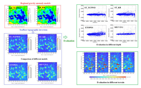
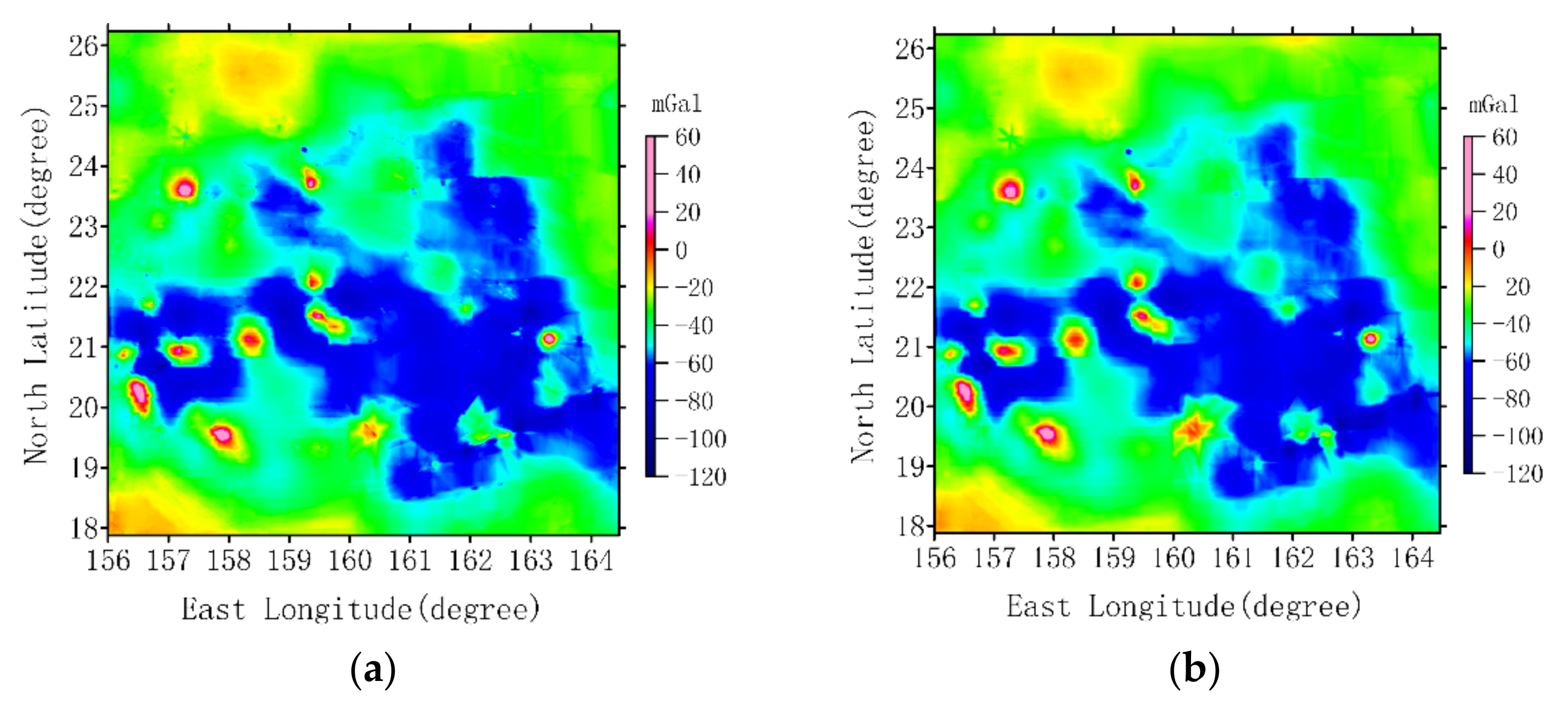
37]. This leads to the existence of some topographic information in the regional gravity anomalies. Hence, we proposed the topography constraint factor weight optimization (TCFWO) method by introducing a topographic factor to optimize the weight of kriging algorithm for regional gravity data interpolation. In the TCFWO method, the horizontal and vertical variogram models of regional gravity data were constructed, and the anisotropic effect of the horizontal variogram was considered. Subsequently, we used the TCFWO method to carry out relevant experiments on Marcus-Wake seamount area to verify the effectiveness and practicability of the method.

2. Construction of TCFWO Method

The free air gravity anomaly, g f x , y , obtained by satellite altimetry, which is assumed to divided into two parts regional and residual anomaly according to the shipborne depth measurements in GGM [38]:
g f x , y = g r e g x , y + g r e s x , y
where x and y represent the latitude and longitude, respectively. g r e g x , y and g r e s x , y denote as the regional and residual gravity anomalies. In the area of relatively flat terrain change, the relationship between topography and the residual gravity can be assumed by a simple Bouguer plate formula [37]:
E x , y = g r e s x , y / 2 p i G ρ + D
where E x , y is the depth value at point x , y . G represents the universal gravitational constant (=6.672 × 10⁻¹¹ N·m2/kg2).   D is the deepest depth of the control points within the study area. Both the value of E x , y and D are negative from the sea level down. ρ is the difference between bedrock density and seawater density. However, in GGM, ρ needs to be optimized as a parameter to adjust the relationship between residual gravity and topography, its analytical significance exceeds the actual physical meaning [19]. The common methods to determine the density contrast include downward continuation method [38] and iterative method [23], in this paper, the latter method was used. By rearranging the Equation (2), the residual gravity anomalies at the control points, x i , y i , i = 1 , 2 , , n , can be calculated:
Δ g r e s C P x i , y i = 2 p i G ρ E C P x i , y i D
where Δ g r e s C P x i , y i are residual gravity anomalies. E C P x i , y i are the depth of control points. Therefore, the corresponding regional gravity anomalies g r e g C P x i , y i can be calculated.
g r e g C P x i , y i = Δ g f C P x i , y i Δ g r e s C P x i , y i
where Δ g f C P x i , y i are the free air gravity anomalies at control points, which can be obtained by bilinear interpolation from the satellite altimetry derived gravity model. Once the residual gravity anomaly model is acquired, the seafloor topography model can be estimated according to Equation (2). However, the regional gravity anomaly model should be constructed first.
Evidentially, the regional gravity anomalies are discrete distribution, hence, it is necessary to grid it. According to the TCFWO method, the construction process of regional gravity field is as follows.
The g r e g C P x i , y i at the control points can be calculated according to Equation (4). Then, the unknown value of regional gravity anomaly, g r e g P P x 0 , y 0 , at the predicted position can be estimated [30] by:
g r e g P P x 0 , y 0 = i = 1 n λ i Δ g l C P x i , y i
where n is the number of control points. x 0 , y 0 is the predicted position coordinate of unknown attribute value. λ i i = 1 , 2 , , n are weight values assigned to the known points, which determine the results of gridding. Hence, the step to determine weight values is crucial.
The estimation of TCFWO method is unbiased and optimal, just like kriging algorithm. Therefore, the estimated value g r e g P P x 0 , y 0 satisfies the following conditions.
E g r e g P P x 0 , y 0 g r e g P P * x 0 , y 0 = 0 , V a r g r e g P P x 0 , y 0 g r e g P P * x 0 , y 0 = m i n
where g r e g P P * x 0 , y 0 is the real value at x 0 , y 0 point. E[·] is the mathematical expectation symbol. Var[·] represents the variance solution symbol. In addition, based on the second-order stationary hypothesis, the variable data satisfies the following two conditions [39]:
E Δ g r e g C P x i , y i = K , K D
Cov Δ g r e g C P x i , y i , Δ g r e g C P x j , y j = E Δ g r e g C P x i , y i · Δ g r e g C P x j , y j K 2 = f h
where K is any constant. Cov · is the covariance calculation symbol of the variable. Δ g r e g C P x i , y i   and   Δ g r e g C P x j , y j are the attribute value of two arbitrary points.   f h is a function only related to the distance h between two variables.
According to the unbiased and error optimal characteristics of TCFWO method for estimation value, a new objective function F λ , ϕ is constructed by combining Equations (5)–(8) and using Lagrange multiplier method. Hence, the problem of determining weight values, λ i , is transformed into the calculation of equation optimization with constraints of i = 1 n λ i 1 = 0 .
F λ , ϕ = Var i = 1 n λ i Δ g r e g C P x i , y i g r e g P P * x 0 , y 0 + 2 ϕ ( i = 1 n λ i 1 ) = 2 i = 1 n λ i γ i 0 d i = 1 n j = 1 n λ i λ j γ i j d γ 00 d + 2 ϕ ( i = 1 n λ i 1 )
where ϕ is the Lagrange coefficient. γ i 0 d is the variogram value between the control point x i , y i and the predicted point x 0 , y 0 . γ i j d is the variogram value between x i , y i and x j , y j . The value of variogram is a statistic describing the spatial correlation of data, which is defined as the variance of the difference between two points. Hence, the γ i 0 d and γ i j d can be calculated by the experimental variogram Equation (10) [30]:
γ d = 1 2 E Δ g r e g C P m Δ g r e g C P m + d 2
where Δ g r e g C P m and Δ g r e g C P m + d are the regional gravity anomaly at position m and m + d .   d is the Euclidean distance between two points namely the lag distance.
Then, the partial derivative of F λ , ϕ with respect to λ i and ϕ are calculated, and the results after derivation are zero. Finally, the equations for determining the weight value are as follows [31]:
i = 1 n λ i = 1 , i = 0 n λ i γ i j d + ϕ = γ i 0 d ,   i , j = 1 , 2 , , n
From the Equation (11), the values of variogram are important for weight determination. However, the ordinary kriging algorithm only considers the influence of two-dimensional factors on variogram values. In order to calculate and optimize the weight values λ i , this paper introduced the topographic factors, z i i = 1 , 2 , n , as the third variable factor based on longitude and latitude coordinates. Thus, the variogram models of gravity anomaly in horizontal and vertical directions could be constructed, respectively, and added by equivalence weight:
γ i j L i j , Z i j = 1 2 γ L i j + γ Z i j γ L i j = 1 2 E Δ g r e g C P x i , y i Δ g r e g C P x j , y j 2 γ Z i j = 1 2 E Δ g r e g C P z i Δ g r e g C P z j 2 , i , j = 1 , 2 , , n
where γ L i j and γ Z i j are the experimental variograms in horizontal and vertical directions, respectively. γ L i j , Z i j is the optimized experimental variogram. The L i j and Z i j are the lag distance in horizontal direction and vertical direction, respectively [40]:
L i j = x i x j 2 + y i y j 2 Z i j = z i z j ,   i , j = 1 , 2 , , n
where x i , y i , z i and x j , y j , z j denote the coordinates of two shipborne measurements control points with known attributes, respectively.
The values calculated by Equation (12) are experimental variogram, which are discrete points. Generally, it is necessary to use the least square algorithm to fit the variogram models based on the theoretical variogram function [41] and determine the better models according to the fitting results. Then, using the determined theoretical function model, the variogram values between the corresponding points are calculated. Finally, the formula of TCFWO method for gridding regional gravity anomaly is expressed as follows:
i = 1 n λ ^ i = 1 , i = 0 n λ ^ i γ i j ¯ L i j , Z i j + ϕ = γ i 0 ¯ L i j , Z i j , g r e g P P x 0 , y 0 = i = 1 n λ ^ i Δ g r e g C P x i , y i , i , j = 1 , 2 , , n
where λ ^ i are the optimized weight values. γ i j ¯ L i j , Z i j are the best fitting variograms of γ L i j , Z i j . Other symbols have the same meaning as above.
Therefore, based on the above analysis, the process of gridding regional gravity anomaly model and inversion of seafloor topography using TCFWO method is as follows.
Firstly, satellite altimetry derived gravity anomaly at the control points, Δ g f C P x , y , are divided into two parts residual information, Δ g r e s C P x , y , and regional information Δ g r e g C P x , y . There the Δ g r e s C P x , y is determined based on the Equation (3).
Secondly, the experimental variogram models of regional gravity anomaly data, Δ g r e g C P x , y , in horizontal and vertical directions are calculated, respectively, according to Equation (12). Based on the theoretical variogram model, the least square algorithm is used to fit the experiment variogram model.
Then, the values of best fitting theoretical variogram are substituted into the TCFWO Equation (14), to realize the grid processing of regional gravity anomaly and construct a model in the region.
Finally, the gridding of regional gravity anomaly model is subtracted from the satellite altimetry derived gravity anomaly model to obtain the residual gravity anomaly model. According to the Equation (2), the topographic model is calculated.

3. Verification of TCFWO Method

3.1. Overview of the Experimental Area and Data Preparation

The Marcus-Wake seamount group in the Western Pacific Ocean (156.00° E–164.47° E, 17.88° N–26.26° N) was selected as the study area. This area has experienced strong volcanic activity, with complex topography and rich natural resources [42]. The high precision seafloor topography is of great significance to the exploitation and utilization of natural resources and marine geological research in the region. The experimental data sources include the shipborne depth measurements data and the satellite altimetry gravity anomaly model, and existing seafloor topographic models.

3.1.1. Shipborne Depth Measurements Data

The distribution depth measurements provided by the National Geophysical Data Center (NGDC) (http://www.ngdc.noaa.gov/mgg, accessed on 2 September 2020) are shown in Figure 1a, there are 53,863 shipborne measurements. One of every five points was selected to form the check data set. There are 10,777 check points, as shown by the blue star dots. The check data set was used to determine the density contrast and evaluate the results of seafloor topography. There are 43,086 remaining points used as control data set for seafloor topography inversion, as shown in red dots. Among them, the maximum depth is −6190.00 m, the minimum depth is −1038.00 m, and the average is −4782.68 m, which suggests the region’s terrain fluctuates sharply.

3.1.2. Satellite Altimetry Derived Gravity Anomaly Data

The satellite altimetry derived gravity anomaly model was provided by the Scripps Institution of Oceanography (SIO) (https://topex.ucsd.edu, accessed on 12 July 2020). As shown in Figure 1b, the version is V28.1 with a resolution of 1′ × 1′. The maximum gravity value in the area is 254.80 mGal, the minimum is −63.00 mGal, and the average is −4.69 mGal. In addition, it also includes the seafloor topography model ETOPO1 (https://www.ngdc.noaa.gov, accessed on 2 November 2020) and V19.1 (https://topex.ucsd.edu, accessed on 12 July 2020) for accuracy comparison, which were analyzed in Section 4.2 below.

3.2. Geostatistical Analysis of Regional Gravity Anomaly Data

Using TCFWO method to grid gravity anomaly model, geostatistical analysis is necessary to master the spatial stationarity and variability of variables comprehensively. Quantile-quantile graphs and variogram models are generally better methods.

3.2.1. Second-Order Stationary Analysis

The TCFWO method is based on kriging algorithm, so the experimental data should satisfy the second-order stationary hypothesis. However, in practice, such data is difficult to exist, and there is no good method to judge the second-order stability. Generally, If the data approximately satisfies the normal distribution, we consider that the data is second-order stationary. Therefore, before gridding the regional gravity anomaly data, it is necessary to test the approximate normality of the data.
The normal distribution test is often analyzed by quantile-quantile diagram, and the regional gravity anomaly data distribution drawn with blue solid dots based on the idea of quantile diagram is shown in Figure 2. According to the figure, the sample data are basically distributed near the red straight line which is normal distribution line. Therefore, we considered that the regional gravity anomaly data approximately satisfies the normal distribution. Indeed, if the data does not normal distribution, it needs to be transformed, such as Box-cox and logarithmic transformation.

3.2.2. Analysis of Spatial Variability Characteristics

It is crucial to master the variability characteristics of data spatial distribution for grid processing. In geo-statistics, the variogram model is used to analyze it, which mainly involves the calculation and fitting of the variogram model and the anisotropic analysis of data. The anisotropy of data means that its variogram is not identical in different directions, that is, the value of range and sill of variogram model are not identical. Instead, if the variogram is the same in different directions, it satisfies isotropy.
  • Construction of variogram model in the horizontal direction
According to the distribution of the regional gravity anomaly data in the horizontal direction, the Equation (13) was used to calculate the distance of points in the horizontal direction as the lag distance. In the calculation of variogram, the east-west direction is represented by 0 and 180 degrees. Therefore, in order to comprehensively analyze the variation properties in different directions, the variogram values in the four directions of 0°, 45°, 90° and 135° were calculated by Equation (12), respectively. The experimental variograms are shown in Figure 3a. From the curve, the range and sill value are different in different directions. Hence, the regional gravity anomaly data is anisotropic in the horizontal direction.
In this paper, the experimental variogram of horizontal direction was established by using the mean values of variogram models in the four directions. The distribution of experimental samples is shown as the black star in Figure 3b. Based on the theoretical variogram models, such as exponential function model, spherical function model and gaussian function model, the least square algorithm was used to fit the experimental variogram curves. The results of the three theoretical variograms fitting are shown in the red triangle line, blue square line and black solid line in Figure 3b, respectively. The statistics of the formula parameters and fitting degree are shown in Table 1.
From the Figure 3b and Table 1, the results of the spherical model and the gaussian model are basically the same, and the R2 is 0.45 and 0.44, respectively. While the result of the exponential model is 0.59, which is better than the other two function models. Therefore, the exponential model was used to calculate the value of the variogram.
2.
Construction of variogram model in vertical direction
Firstly, variogram values and the lag distance in vertical direction were calculated based on Equations (12) and (13), respectively. Then, according to the horizontal variogram fitting method, the variogram fitting curve in the vertical direction is shown in Figure 4 and the fitting results are shown in Table 2.
According to Figure 4 and Table 2, the fitting results of the three theoretical variation function models are similar. By comparison the value of R2, the values of spherical model and Gaussian model are 0.94 and 0.93, respectively. However, the value of the exponential model is 0.97, which shows that the fitting accuracy is better. Therefore, the exponential model was used in the construction of the variogram model in vertical direction.

3.3. Accuracy Assessment of Regional Gravity Anomaly Model

Combined with Equations (2)–(4) the discrete regional gravity anomalies of shipborne depth control points position in Section 3.1 can be calculated. In order to verify the applicability of TCFWO method, results of this method and kriging algorithm in gridding regional gravity anomalies were compared. Two methods were used to build GR_TCFWO (Figure 5a) and GR_KR (Figure 5b) models with 1′ × 1′ resolution, respectively, and the leave-one-out cross-validation method was used to evaluate model’s accuracy [43]. The process of cross-validation method is to first remove one point in the regional gravity anomaly data set, and then use the remaining points to predict the gravity value at that location. Then add the excluded point back to the dataset and remove another point. Do this 1000 times for samples in the dataset and compare the differences between the estimated and true values of the selected samples. Taking the estimated values of the model as the abscissa and the true values as the ordinate, the constructed scatter diagram and its regression fitting curve are shown in Figure 6. The statistical results of the difference between the two values are shown in Table 3b.
From the Figure 5, the two models are basically consistent in the whole, but there are obvious differences in some areas with sparse control points. According to the statistical results in Table 3a, the values range of GR_TCFWO model is larger than GR_KR model, but the standard deviation of GR_TCFWO model is slightly lower than GR_KR model. Therefore, the TCFWO method increased the value range of the regional gravity anomaly model, which may have revealed more details, and the stability of the model was slightly improved. From the Figure 6a,b, the results showed that the GR_KR values were typically more scatter compared to GR_TCFWO values, which indicated a lower correlation with sample values. Therefore, TCFWO method could construct a higher accuracy model than kriging method.
From the Table 3b showed that the standard deviation (STD) of cross-validation results of GR_TCFWO model was 3.62 mGal, the R2 of liner regression is 0.98. By comparison, the STD of GR_KR model is 6.08 mGal, the R2 is 0.92. The results showed that the accuracy of model constructed by the TCFWO method was about 40% higher than that of the ordinary kriging algorithm. Hence, the TCFWO method was more effective in gridding. Subsequently, in order to further prove the advantages of the TCFWO method, two gravity anomaly models were used to invert seafloor topography.

4. Inversion and Comparison of Seafloor Topography

The regional gravity anomaly models established by the above two methods provide basic data for seafloor topography inversion. According to the principle of GGM, the quality of the regional gravity anomaly model is important to the accuracy of seafloor topography inversion. Therefore, it is necessary to analyze the inversion results.

4.1. Determination of Density Contrast

Density contrast, ρ , is the difference between bedrock density and seawater density, which is important to adjust the relationship between gravity and seafloor topography. Generally, the density of the global ocean bedrock is 2.70 g/cm3 (1 g/cm3 = 103 kg/m3) which is the mean value between 2.67 g/cm3 and 2.73 g/cm3 [19], and the average density of the seawater is 1.03 g/cm3, so the density constant is 1.67 g/cm3. However, it is not suitable to use the average value for the inversion of local topography, the density constant should be accurately determined. The commonly used methods are the iterative method and the downward continuation method, among which the iterative method is widely used, since it is simple and convenient when there are more control points.
Based on the iterative density constant determination method proposed by Kim, J.W. [23], 43,086 control points and 10,777 check points were selected, and their distribution was as show Figure 1a. Then, the control points were used to estimate the seafloor topography model under different density constants, and bilinear interpolation was used to obtain the predicted topographic values at the location of the check points. By comparing the correlation coefficient and the difference standard deviation between the predicted values and the actual values, we constructed the curve Figure 7.
According to Figure 7a,b the correlation coefficient increases and the STD with ρ increases in a certain range. When the density contrast is greater than a certain constant, the correlation coefficient decreases and the STD increases. Through the above-mentioned calculation and fitting of the two curves, the density constant was about 1.11 g/cm3, the correlation coefficient curve reached the maximum value and STD was the minimum value. Therefore, in this paper the optimal density contrast 1.11 g/cm3 was used to estimate seafloor topography.

4.2. Accuracy Comparison and Analysis of Seafloor Topography Models

In order to further illuminate the advantages of the TCFWO method compared with kriging method, the following focuses on the analysis of the inverted seafloor topography models. Firstly, the satellite altimetry gravity anomaly model V28.1 was used to subtract GR_TCFWO and GR_KR models constructed in Section 3.3, respectively, and the residual gravity anomaly model was obtained. Then, the corresponding seafloor topography model ST_TCFWO (Figure 8a) and ST_KR (Figure 8b) were obtained by the Equation (2). Finally, the accuracy of inversion models was compared and analyzed by using the shipborne measurements data and existing models such as the ETOPO1 (Figure 8c) and V19.1 (Figure 8d).
From the Figure 8, the geomorphic features of the Marcus-Wake seamount group area shown by each model are basically the same in general. However, there are some differences in the local values, which can be seen from the statistical results of the average and STD in Table 4. Obviously, the STD of difference between ST_TCFWO model and ST_KR model was 42.50 m, which was the smallest. In comparison, the STD of difference between ST_TCFWO model and V19.1 model is 213.85 m and ETOPO1 model is 208.83 m, respectively. However, the STD of the difference between the ST_KR model and the general models are 221.75 m and 210.17 m, respectively. Therefore, the ST_TCFWO model is closer to the international general model.
In addition, the two international models V19.1 and ETOPO1 are also different. The mean value of difference between them is −9.4 m, and the STD is 202.32 m. The reasons may be related to their construction methods. ETOPO1 model was mainly based on the seafloor topography of V8.2 inverted by satellite altimetry, and then integrated the shipborne depth data for interpolation and smoothing [44]. However, V19.1 was predicted by satellite altimetry and sparse shipboard bathymetry. Compared with V8.2, V19.1 model has higher accuracy and resolution.
Through the above comparison, there are some differences among the four models. Moreover, both the international general seafloor topographic models and the models predicted by gravity in this paper can’t completely guaranteed to be correct, especially in the area where there are no shipborne depth control points. Therefore, this paper analyzed the accuracy of the seafloor topographic model by using the external check points, namely four models were interpolated to 10,777 shipborne depth measurements inspection points (Figure 1) using bilinear interpolation, and the difference between model values and checking values were compared, the statistical results of are shown in Table 5.
According to the Table 5, by comparing the STD, the model accuracy in the study area from high to low is V19.1 model, ST_TCFWO model, ST_KR model and ETOPO1 model. The STD values are 117.86 m, 129.14 m, 173.51 m and 191.71m, respectively. The correlation coefficient between the model and the shipborne sounding measurements inspection data, the accuracy can also be reflected. In contrast, the accuracy of V19.1 model is better than ST_TCFWO model. Analyzing the reasons, on one hand, the inversion band of V19.1 model was controlled in the range of 15 km to 160 km, and the shipborne measured data were used in the long wavelength part of topography [14]. On the other hand, it needs to be further explored whether the shipborne check points for model accuracy evaluation were also applied to the V19.1 model construction. However, it is obvious that the accuracy of ST_TCFWO model is better than ETOPO1 and ST_KR model. Compared with the ST_KR model (STD = 173.51 m), the accuracy of the ST_TCFWO model (STD = 129.14 m) was improved about 26%. Therefore, it is reflected that the TCFWO method has obvious advantages compared with the ordinary kriging algorithm in application of inversion seafloor topography. To compare the difference of each model in different depth, the variation of residual values between model values and checking values with depth was drawn, as shown in Figure 9. The results show that with the increase of depth, the residual values of the four models tend to zero value. Comparing the Figure 9a with Figure 9b,c, the results of ST_TCFWO model are more aggregated, which indicates the inversion advantage of TCFWO method. In contrast, the data distribution of V19.1 model is closest to the value of zero, which indicates that the model values are more consistent with the checking values overall. It is also consistent with the conclusion of the above analysis.
To further analyze the accuracy of the model at different depths, the depth variation of the check points was taken as the standard. Taking a depth layer every 1000 m, and the above residual values of models in each different depth layers was shown in Table 6. With the increase of depth, the checking accuracy of ST_KR model improved. The verification accuracy of ST_TCFWO model, ETOPO1 model and V19.1 model first decreases and then increases with the increase of depth, and all reached the maximum STD in the depth range of −2000 m to −3000 m. The maximum STD of each model was 235.16 m, 420.47 m and 249.57 m, respectively. Therefore, the stability of ST_TCFWO model is basically consistent with international models. Furthermore, in the range of −1000~−3000 m and more than −6000 m, ST_TCFWO model is better than the other three models. However, in the range of −3000 m to −6000 m (which is also the range where most of the check points gather), the accuracy of models from high to low was V19.1, ST_TCFWO, ST_KR and ETOPO1. This is a very interesting result. In this depth range, the accuracy of V19.1 model is better. The specific reasons need further discussion in future. However, it is obvious that ST_TCFWO model has better accuracy than ST_KR model in all ranges, indicating an advantage of TCFWO method.
Then, as shown in Figure 10, the model with sparse distribution of control points (160.00° E–164.47° E, 17.88° N–26.26° N) was intercepted to further analyze the influence of control points on model accuracy. There are 14,364 control points and 3572 check points. Bilinear interpolation was used to calculate the model values of the seafloor topographic models at the check points. The statistical results of the difference between model values and checking values are shown in Table 7. We defined relative precision as the ratio of the difference values to the shipborne depth checking values. RESTD in the table is the standard deviation of relative precision. In this paper, the mean value of RESTD of each model was taken as the criterion to judge the large difference.
If the relative accuracy is greater than the mean of RESTD value (8.26%), it is considered as a large difference point. The distribution of large difference points was shown in the red dots in Figure 10. We can see that the red dots are basically distributed near the ridge and seamount where the topographic changes dramatically. Among them, ETOPO1 has the largest number of red dots and V19.1 has the smallest number. The distribution of red points in ST_TCFWO model is like that in ST_KR. However, in some regions, the number of dots in ST_TCFWO is significantly less than ST_KR. From the distribution of red dots in the map, the accuracy of the model is affected by the drastic change of terrain. We think that the reasons may be as follows: (1) The accuracy of gravity anomaly obtained by satellite altimetry is reduced due to the sharp relief of topography. (2) Most of the seamount in the study area were formed during the mid-Cretaceous, resulting in a large amount of sediment accumulation. Therefore, the correlation between gravity anomaly and seafloor topography is reduced.
From the Table 7, the extreme, mean values and STD of ST_TCFWO local model are smaller than that of three other models, with the highest accuracy among the four models. Comparing with the local of ST_KR model (STD = 207.59 m), the accuracy of ST_TCFWO local model was improved by about 26.35%. Moreover, comparing Table 5 and Table 7 above, due to the reduction of control points, the accuracy of the four models is significantly reduced and the accuracy change rate is different. The STD of local of ST_TCFWO model is 152.88 m, compared with ST_TCFWO model (STD = 129.14 m), the accuracy change rate is 18.38%. The STD change rate of ST_KR is 19.64%. More obvious is the V19.1 model, with a change rate of 35.47%. Obviously, the ST_TCFWO model is better than ST_KR in both accuracy and stability, and is less affected by the distribution of control points.
Subsequently, the accuracy of four local seafloor topographic models in different areas was compared. We delineate two areas A and B with different geomorphic types for analysis, as shown in Figure 10. The control points in area A and B are rare and distributed discretely. In addition, the terrain of area A is relatively flat, mostly abyssal plain landform. In area B, there are seamounts, ridge and other landforms, and the terrain changes dramatically. The shipborne measurements check points in the two areas are used to evaluate the accuracy of models. The results of difference between the model values and checking values were shown in Table 8.
From the Table 8, in the area A, the accuracy of V19.1 model was the best. The second was ST_TCFWO model, its STD was 46.62 m. The accuracy ST_KR model was the lowest, and the STD was 66.36 m. In the area B, the accuracy of ST_TCFWO model was better than the other three models. However, the accuracy of the four models was not ideal. This result was consistent with the distribution of red relative precision points in Figure 10. It is worth affirming that ST_TCFWO model has better accuracy than ST_KR model no matter in flat submarine plain or rugged seamount area, which shows the superiority of TCFWO method.

5. Conclusions

When GGM is used to invert seafloor topography, due to the distribution of control points, it is necessary to grid the regional gravity anomaly model by using interpolation method, thereby, to improve the accuracy of seafloor topography. A study area of Marcus-Wake seamount group was selected to evaluate the reliability of the TCFWO method. Then, TCFWO and kriging methods were used to grid the regional gravity anomaly, and then the corresponding seafloor topography models were inversed. Finally, the inversion models were compared with shipborne depth measurements data and existing models, including ETOPO1 and V19.1, respectively. The following useful conclusions were drawn.
  • The cross-validation results show that the STD of the GR_TCFWO regional gravity anomaly model gridded by TCFWO method was 3.63 mGal, which was more accurate than the GR_KR model constructed by the ordinary kriging algorithm nearly 40%. Hence, TCFWO method has optimized the interpolation weight of kriging algorithm by introducing topography constraint factor, and has obtain a better grid model. The GR_TCFWO model is a better data for seafloor topography inversion.
  • The accuracy of the models was evaluated by using the shipborne sounding data. The STD of ST_TCFWO model was 129.14 m, and its accuracy was slightly lower than that of V19.1 model and better than the ST_KR and ETOPO1 models. Comparing with the ST_KR, and the accuracy of ST_TCFWO model was improved by about 26%. The accuracy of the models was affected by the change of depth. In each depth layer, the accuracy of ST_TCFWO model was better than that of ST_KR model. Moreover, ST_TCFWO model showed better advantages than other models in the depth layer of −1000 m~−3000 m and more than −6000 m.
  • The accuracy of the model was affected by the distribution of control points, but the influence on ST_TCFWO model was relatively small. In the area with sparse shipborne measured control points, the accuracy of ST_TCFWO model was better than ST_KR, ETOPO1 and V19.1 model. By analyzing the model in different topographic features, the accuracy of the model was greatly affected by the terrain changes and the points with low relative accuracy were mainly distributed in the locations where the terrain changes violently. However, ST_TCFWO model has better accuracy than ST_KR model no matter in flat submarine plain or rugged seamount and ridge area, which shows the superiority of TCFWO method.

Author Contributions

Y.S. and W.Z. designed the research; Y.S. and Z.L. performed experiments; Y.S., Z.L., W.Z. and Z.Z. wrote this paper. All authors have read and agreed to the published version of the manuscript.

Funding

This work was supported in part by the National Natural Science Foundation of China under Grant (41774014, 41574014), in part by the Liaoning Revitalization Talents Program under Grant (XLYC2002082), in part by the Frontier Science and Technology Innovation Project and the Innovation Workstation Project of Science and Technology Commission of the Central Military Commission under Grant (085015), and in part by the Outstanding Youth Fund of China Academy of Space Technology.

Acknowledgments

The authors are thankful to the National Geophysical Data Center for providing the depth data of the shipborne measurements and the ETOPO1 seafloor topography model, and thankful to the University of California San Diego website for providing the V28.1 gravity anomaly data and V19.1 seafloor topography model. YongJin Sun, Wei Zheng and Zhaowei Li contributed equally to this paper.

Conflicts of Interest

The authors declare no conflict of interest.

References

  1. Li, Z.; Zheng, W.; Wu, F.; Fang, J. Improving the matching efficiency of underwater gravity matching navigation based on a new hierarchical neighborhood threshold method. Chin. J. Geophys. 2019, 62, 2405–2416. [Google Scholar]
  2. Hwang, C.; Kao, E.; Parson, B. Global derivation of marine gravity anomalies from Seasat, Geosat, ERS-1 and TOPEX/POSEIDON altimeter data. Geophys. J. Int. 1998, 134, 449–459. [Google Scholar] [CrossRef] [Green Version]
  3. Marks, K.M.; Smith, W.H.F. Radially symmetric coherence between satellite gravity and multibeam bathymetry grids. J. Mar. Res. 2012, 33, 223–227. [Google Scholar] [CrossRef]
  4. Andersen, O.B.; Knudsen, P. Global marine gravity field from the ERS-1 and Geosat geodetic mission altimetry. J. Geophys. Res. 1998, 103, 8129–8137. [Google Scholar] [CrossRef]
  5. Ménard, Y.; Fu, L.; Escudier, P.; Parisot, F.; Perbos, J.; Vincent, P.; Desai, S.; Haines, B.; Kunstmann, G. The Jason-1 Mission Special Issue: Jason-1 Calibration/Validation. Mar. Geod. 2003, 26, 131–146. [Google Scholar] [CrossRef]
  6. Juliette, L.; Rosemary, M.; Fu, L.; Josh, K.W.; Bonekamp, H.; Lillibridge, J.; Perbos, J.; Zaouche, G.; Vaze, P.; Bannoura, W.; et al. The OSTM/Jason-2 Mission. Mar. Geod. 2010, 33, 4–25. [Google Scholar]
  7. Zhu, C.; Guo, J.; Hwang, C.; Gao, J.; Yuan, J.; Liu, X. How HY-2A/GM altimeter performs in marine gravity derivation: Assessment in the South China Sea. Geophys. J. Int. 2019, 219, 1056–1064. [Google Scholar] [CrossRef]
  8. Hwang, C.; Parsons, B. An optimal procedure for deriving marine gravity from multi-satellite altimetry. Geophys. J. Int. 1996, 125, 705–718. [Google Scholar] [CrossRef] [Green Version]
  9. Sandwell, D.T.; Smith, W.H.F. Marine gravity anomaly from Geosat and ERS 1 satellite altimetry. J. Geophys. Res. 1997, 102, 10039–10054. [Google Scholar] [CrossRef] [Green Version]
  10. Neumann, G.A.; Forsyth, D.W.; Sandwell, D.T. Comparison of marine gravity from shipboard and high-density satellite altimetry along the Mid-Atlantic Ridge, 30.5–35.5S. Geophys. Res. Lett. 2013, 20, 1639–1642. [Google Scholar] [CrossRef] [Green Version]
  11. Sandwell, D.T.; Garcia, E.M.; Soofi, K.; Wessel, P.; Chandler, M.; Smith, W.H.F. Toward 1-mGal accuracy in global marine gravity from CryoSat-2, Envisat, and Jason-1. Lead. Edge 2013, 32, 892–899. [Google Scholar] [CrossRef] [Green Version]
  12. Bao, L.; Xu, H.; Li, Z. Towards a 1 mGal accuracy and 1 min resolution altimetry gravity field. J. Geod. 2013, 87, 961–969. [Google Scholar] [CrossRef]
  13. Hwang, C. A bathymetric model for the South China Sea from satellite altimetry and depth data. Mar. Geodesy. 1999, 22, 37–51. [Google Scholar] [CrossRef]
  14. Smith, W.H.F.; Sandwell, D.T. Bathymetric prediction from dense satellite altimetry and sparse shipboard bathymetry. J. Geophys. Res. 1994, 99, 21803–21824. [Google Scholar] [CrossRef]
  15. Smith, W.H.F.; Sandwell, D.T. Global Sea Floor Topography from satellite altimetry and ship depth soundings. Science 1997, 277, 1956–1962. [Google Scholar] [CrossRef] [Green Version]
  16. Hsiao, Y.; Hwang, C.; Cheng, Y.; Chen, L.; Hsu, H.; Tsai, J.; Liu, C.; Wang, C.; Liu, Y.; Kao, Y. High-resolution depth and coastline over major atolls of South China Sea from satellite altimetry and imagery. Remote Sens. Environ. 2016, 176, 69–83. [Google Scholar] [CrossRef]
  17. Fan, D.; Li, S.; Li, X.; Yang, J.; Wan, X. Seafloor Topography Estimation from Gravity Anomaly and Vertical Gravity Gradient Using Nonlinear Iterative Least Square Method. Remote Sens. 2021, 13, 64. [Google Scholar] [CrossRef]
  18. Dixon, T.H.; Naraghi, M.; McNutt, M.K.; Smith, S.M. Bathymetric prediction from SEASAT altimeter data. J. Geophys. Res. 1983, 88, 1563–1571. [Google Scholar] [CrossRef]
  19. Kim, K.B.; Hsiao, Y.S.; Kim, J.W.; Lee, B.Y.; Kwon, Y.K.; Kim, C.H. Bathymetry enhancement by altimetry-derived gravity anomalies in the East Sea (Sea of Japan). Mar. Geophys. Res. 2010, 31, 285–298. [Google Scholar] [CrossRef]
  20. Ramillien, G.; Wright, I.C. Predicted seafloor topography of the New Zealand region: A nonlinear least squares inversion of satellite altimetry data. J. Geophys. Res. 2000, 105, 16577–16590. [Google Scholar] [CrossRef]
  21. Fan, D.; Li, S.; Meng, S.; Xing, Z.; Li, X. Predicting submarine topography by linear regression analysis. J. Chin. Inert. Tech. 2018, 26, 30–38. [Google Scholar]
  22. Ibrahim, A.; Hinze, W.J. Mapping buried bedrock topography with gravity. Ground Water 1972, 10, 18–23. [Google Scholar] [CrossRef]
  23. Kim, J.W.; von Frese, R.B.; Lee, B.Y.; Roman, D.R.; Doh, S.J. Altimetry-derived gravity predictions of bathymetry by the gravity-geologic method. Pure Appl. Geophys. 2011, 168, 815–826. [Google Scholar] [CrossRef]
  24. Xiang, X.; Wan, X.; Zhang, R.; Li, Y.; Sui, X.; Wang, W. Bathymetry inversion with the gravity-geologic method: A study of long-wavelength gravity modeling based on adaptive mesh. Mar. Geodesy 2017, 40, 329–340. [Google Scholar] [CrossRef]
  25. Kim, K.B.; Yun, H.S. Satellite-derived bathymetry prediction in shallow waters using the gravity-geologic method: A case study in the West Sea of Korea. KSCE J. Civ. Eng. 2018, 22, 2560–2568. [Google Scholar] [CrossRef]
  26. Xing, J.; Chen, X.; Ma, L. Bathymetry inversion using the modified gravity-geologic method: Application of the rectangular prism model and Tikhonov regularization. Appl. Geophys. 2020, 17, 377–389. [Google Scholar] [CrossRef]
  27. Smith, W.H.F.; Wessel, P. Gridding with continuous curvature splines in tension. Geophysics 1990, 55, 293–305. [Google Scholar] [CrossRef]
  28. Bartier, P.M.; Keller, C.P. Multivariate interpolation to incorporate thematic surface data using inverse distance weighting (IDW). Comput. Geosci. 1996, 22, 795–799. [Google Scholar] [CrossRef]
  29. Zala, V.; Shankar, V.; Sastry, S.P.; Kirby, R.M. Curvilinear Mesh Adaptation Using Radial Basis Function Interpolation and Smoothing. J. Sci. Comput. 2018, 77, 397–418. [Google Scholar] [CrossRef] [Green Version]
  30. Oliver, M.A.; Webster, R. Kriging: A method of interpolation for geographical information systems. Int. J. Geogr. Inf. Syst. 1990, 4, 313–332. [Google Scholar] [CrossRef]
  31. Chen, D.; Liu, D.; Zeng, X.; Meng, L.; Yang, X. Application and improvement of spatial temporal Kriging in geomagnetic field interpolation. Chin. J. Geophys. 2016, 59, 1743–1752. [Google Scholar]
  32. Musafer, G.N.; Thompson, M.H.; Kozan, E.; Wolf, R.C. Spatial pair-copula modeling of grade in ore bodies: A case study. Nat. Resour. Res. 2017, 26, 223–236. [Google Scholar] [CrossRef]
  33. Koziel, S.; Pietrenko-Dabrowska, A. Rapid multi-objective optimization of antennas using nested kriging surrogates and single-fidelity EM simulation models. Eng. Comput. Int. J. Comput. Aided Eng. 2019, 37, 1491–1512. [Google Scholar] [CrossRef]
  34. Bhattacharjee, S.; Ghosh, S.K. Time-series augmentation of semantic kriging for the prediction of meteorological parameters. In Proceedings of the IEEE International Geoscience and Remote Sensing Symposium, Milan, Italy, 26–31 July 2015. [Google Scholar]
  35. Vidhya, B.; Vidhyapriya, R. Kriging interpolation technique with triangulated irregular network for image compression using image inpainting. J. Comput. Theor. Nanosci. 2017, 14, 5756–5760. [Google Scholar] [CrossRef]
  36. Cattle, J.A.; McBratney, A.B.; Minasny, B. Kriging Method Evaluation for Assessing the Spatial Distribution of Urban Soil Lead Contamination. J. Environ. Qual. 2002, 31, 1576–1588. [Google Scholar] [CrossRef]
  37. Wan, X.; Ran, J.; Jin, S. Sensitivity analysis of gravity anomalies and vertical gravity gradient data for bathymetry inversion. Mar. Geophys. Res. 2019, 40, 87–96. [Google Scholar] [CrossRef]
  38. Hsiao, Y.S.; Kim, J.W.; Kim, K.B.; Bang, Y.L.; Hwang, C.W. Bathymetry estimation using the gravity-geologic method: An investigation of density contrast predicted by the downward continuation method. Terr. Atmos. Ocean. Sci. 2011, 22, 347–358. [Google Scholar] [CrossRef] [Green Version]
  39. Pardo-Iguzquiza, E.; Dowd, P.A. The second-order stationary universal Kriging model revisited. Math. Geol. 1998, 30, 347–378. [Google Scholar] [CrossRef]
  40. Yang, C.S.; Zhang, Q.; Zhang, S.; Zhao, Y. Research on GPS water vapor interpolation by improved Kriging algorithm. Remote Sens. Land Res. 2013, 25, 39–44. [Google Scholar]
  41. Iaco, S.D.; Myers, D.E.; Posa, D. The linear coregionalization model and the product-sum space-time variogram. Math. Geol. 2003, 35, 25–38. [Google Scholar] [CrossRef]
  42. Ren, X.; Glasby, G.P.; Liu, J.; Shi, X.; Yin, J. Fine-scale compositional variations in a Co-rich Mn crust from the Marcus-Wake Seamount cluster in the western Pacific based on electron microprobe analysis (EMPA). Mar. Geophys. Res. 2007, 28, 165–182. [Google Scholar] [CrossRef]
  43. James, G.; Witten, D.; Hastie, T.; Tibshirani, R. Resampling methods. An Introduction to Statistical Learning: With Applications in R.; Casella, G., Fienberg, S., Olkin, I., Eds.; Springer: New York, NY, USA, 2013; Volume 103, pp. 175–201. [Google Scholar]
  44. Tozer, B.; Sandwell, D.T.; Smith, W.H.F.; Olson, C.; Beale, J.R.; Wessel, P. Global Bathymetry and Topography at 15Arc Sec: SRTM15+. Earth Space Sci. 2019, 6, 1847–1864. [Google Scholar] [CrossRef]
Figure 1. Experimental data of the study area. (a) Distribution of shipborne depth measurements points. The details of the yellow box area are shown in the small picture on the right. The red solid dots are check data. The blue star dots are control data. (b) Gravity anomaly data by satellite altimetry.
Remotesensing 13 02277 g001
Figure 2. Quantile figure of regional gravity anomaly data. The red line represents a normally distributed line. The blue solid dots represent the regional gravity anomaly data distribution.
Remotesensing 13 02277 g002
Figure 3. Analysis results of spatial variability analysis. (a) Experimental variograms in different directions. (b) The results of variogram fitting.
Remotesensing 13 02277 g003
Figure 4. Variogram value distribution and fitting results in vertical direction.
Remotesensing 13 02277 g004
Figure 5. Regional gravity anomaly model, namely the discrete data interpolation results. (a) GR_TCFWO model map constructed by TCFWO method. (b) GR_KR model map constructed by kriging algorithm.
Remotesensing 13 02277 g005
Figure 6. Cross-validation fitting regression curve, thereinto, the blue dots are 1000 validation data and red line is regress line. (a) Cross-validation result of GR_TCFWO model. (b) Cross-validation result of GR_KR model.
Remotesensing 13 02277 g006
Figure 7. Parameter selection of density contrast. (a) Correlation coefficient curve. (b) Standard deviation curve.
Remotesensing 13 02277 g007
Figure 8. Seafloor topographic models with 1′ × 1′ resolution. (a) ST_TCFWO model which was inverted using the GR_TCFWO model. (b) ST_KR model was estimated using the GR_KR model. (c) ETOPO1 model from NGDC. (d) V19.1 model from SIO.
Remotesensing 13 02277 g008
Figure 9. The curve of residual values with depth. (a) ST_TCFWO model (b) ST_KR model (c) ETOPO1 model (d) V19.1 model.
Remotesensing 13 02277 g009
Figure 10. Local seafloor topographic model, namely, the part intercepted from Figure 8, in which the shipborne control points are relatively sparse. ST_TCFWO model, ST_KR model, ETOPO1 model and V19.1 model are shown from left to right. The red dots are the check points with relative accuracy greater than 8.26%. The number of dots in each model is 228, 357, 399 and 106, respectively. The yellow box area was used to analyze the model accuracy under different sea areas.
Remotesensing 13 02277 g010
Table 1. Fitting results of three theoretical variograms models in horizontal direction.
ModelRange (Degree)Sill (mGal2)Nuggets (mGal2)R2
exponential model5.12364.16339.350.59
spherical model0.46480.3721.350.45
gaussian model0.23412.4789.380.44
Note. R2 namely R-squared represents the degree of fitting, the greater the value, the higher the degree of fitting and the value range is 0~1.
Table 2. Three theoretical variograms are used to fit the experimental variograms in vertical direction.
ModelRange (Degree)Sill (mGal2)Nuggets (mGal2)R2
exponential model0.01596.37130.710.97
spherical model0.02475.40197.050.94
gaussian model0.01426.02214.110.93
Table 3. Statistical table of model and cross-validation information. (a) Information of regional gravity anomaly models. (b) Statistics of the difference between the estimate values and the true values of cross-validation results. (unit: mGal).
Model(a)(b)
Min.Max.MeanSTDMin.Max.MeanSTDR2
GR_KR−97.1849.70−43.9416.15−48.4239.08−0.136.080.92
GR_TCFWO−119.3056.73−44.0316.13−31.5120.230.073.620.98
Note. min. = minimum value; max. = maximum value; STD = standard deviation; The meaning of R2 is the same as Table 1.
Table 4. Statistics of model differences, namely the differences between the four models. (unit: m).
ModelMin.Max.MeanSTD
ST_TCFWO−V19.1−1877.322718.78−2.56213.85
ST_TCFWO−ETOPO1−1686.312034.48−11.96208.83
ST_KR−V19.1−2025.382692.17−4.90221.75
ST_KR−ETOPO1−1690.792038.84−14.30210.17
ST_TCFWO−ST_KR−769.33862.142.3442.50
V19.1−ETOPO1−2096.861725.66−9.40202.32
Note. min. = minimum value; max. = maximum value; STD = standard deviation.
Table 5. The difference statistical results of seafloor topography model, namely the difference between four models and the check points of the shipborne depth measurements. (unit: m).
ModelMin.Max.MeanSTDR2
ST_TCFWO−1677.202335.16−1.57129.140.995
ST_KR−1739.772569.200.02173.510.991
ETOPO1−1855.312733.652.18191.710.990
V19.1−2112.942484.363.93117.860.996
Note. min. = minimum value; max. = maximum value; STD = standard deviation. The meaning of R2 is the same as Table 1.
Table 6. Statistical analysis of model checking results with depth variation. (unit: m).
Depth Variation RangeModelMin.Max.MeanSTD
−1000~−2000 (809)ST_TCFWO−1677.202335.16−29.48222.75
ST_KR−1739.772569.20−50.67315.57
ETOPO1−881.072733.6583.47238.29
V19.1−668.162484.3660.33223.62
−2000~−3000 (726)ST_TCFWO−1181.092039.4520.64235.16
ST_KR−1496.342159.4840.55311.56
ETOPO1−1355.782274.2389.86420.47
V19.1−1328.032266.0058.41249.57
−3000~−4000 (856)ST_TCFWO−1449.411487.53−4.15226.51
ST_KR−1011.261479.019.14301.52
ETOPO1−1855.311360.57−14.14339.65
V19.1−1110.481561.9213.53162.11
−4000~−5000 (1300)ST_TCFWO−833.231512.127.49153.35
ST_KR−1247.161504.4317.68199.54
ETOPO1−1676.951385.66−10.98220.53
V19.1−2112.941512.87−3.58140.15
−5000~−6000 (6811)ST_TCFWO−492.59394.46−1.6258.08
ST_KR−582.47492.09−2.1175.10
ETOPO1−1080.53459.09−12.0281.66
V19.1−465.07583.23−7.7636.27
<−6000 (275)ST_TCFWO−152.5482.19−12.1333.04
ST_KR−200.5681.72−17.8744.88
ETOPO1−396.73111.235−5.8142.92
V19.1−655.6268.06−12.6150.15
Note. min. = minimum value; max. = maximum value; STD = standard deviation. The number of check points is indicated in brackets.
Table 7. The results of the difference between the local model and the shipborne survey check points. (unit: m).
ModelMin.Max.MeanSTDRESTDRate
ST_TCFWO−1667.872294.040.72152.886.69%18.38%
ST_KR−1735.562556.003.59207.599.37%19.64%
ETOPO1−1840.632713.1521.09210.098.36%10.06%
V19.1−2020.822458.6911.48159.668.63%35.47%
Note. min. = minimum value; max. = maximum value; STD = standard deviation. RESTD= the standard deviation of relative precision. Rate is the standard deviation change of comparison with the overall statistical results in Table 5 which represents the stability of the model.
Table 8. Accuracy comparison of local models in different sea areas (unit: m).
AreaModelMax.Min.MeanSTD
AST_TCFWO134.94−248.81−11.5446.62
ST_KR292.76−185.48−14.2866.36
ETOPO1284.44−257.613.4455.14
V19.1113.50−92.312.7821.14
BST_TCFWO1031.46−1456.2532.47453.13
ST_KR1432.51−1250.2766.07638.90
ETOPO11324.23−1840.6365.64546.57
V19.12221.79−2020.82174.68654.51
Note. min. = minimum value; max. = maximum value; STD = standard deviation.
Publisher’s Note: MDPI stays neutral with regard to jurisdictional claims in published maps and institutional affiliations.

