Article

Robust Clutter Suppression and Ground Moving Target Imaging Method for a Multichannel SAR with High-Squint Angle Mounted on Hypersonic Vehicle

1
National Laboratory of Radar Signal Processing, Xidian University, Xi’an 710071, China
2
Department of Electrical and Computer Ehgineering, National University of Singapore, Singapore 119077, Singapore
*
Author to whom correspondence should be addressed.
Remote Sens. 2021, 13(11), 2051; https://doi.org/10.3390/rs13112051
Submission received: 10 April 2021 / Revised: 15 May 2021 / Accepted: 20 May 2021 / Published: 22 May 2021

Abstract

:
This paper investigates a robust clutter suppression and detection of ground moving target (GMT) imaging method for a multichannel synthetic aperture radar (MC-SAR) with high-squint angle mounted on hypersonic vehicle (HSV). A modified coarse-focused method with cubic chirp Fourier transform (CFT) is explored first that permits the coarsely focused imageries to be recovered, thus alleviated the impacts of GMT Doppler ambiguity and range cell migration (RCM). After that, in combination with joint-pixel model, a robust clutter suppression method which enhances the GMT integration, and improving the accuracy of radial speed (RS) recovery by modifying the matching between the beamformer center and GMT, is proposed. Due to that the first-order phase compensation and RS retrieval are predigested, the proposed algorithm has lower the algorithmic complexity. Finally, the feasibility of our proposed method are verified via experimental results based on simulated and real measured data.

1. Introduction

Recently, the hypersonic vehicle (HSV) which works in the near-space had received great interests, as it provides the tremendous potential to significantly bridge the gap between air-borne and space-borne remote sensing [1,2]. The HSV-borne synthetic aperture radar (HSV-SAR) possesses a speed advantage and a wider observed area, over the air-borne SAR [3,4,5]. On the other hand, it has a flexible detection range and lower power requirements compared to the space-borne SAR [4]. Compare with the classical SAR, it exhibits the characteristics of fast responsiveness, multiple revisers, and persistent detections, due to its high-speed (e.g., 5 to 20 Mach), high-maneuverability, and global reaching [6,7,8,9].
The side-looking SAR, with a static beam direction, has narrow coverage [10,11,12,13,14]. Whereas the squint-looking SAR [15], due to its variable beam direction, achieves the flexibility of able to revisit interesting regions. More importantly, a high-squint SAR [16,17], with a squint angle of over 45°, is capable of detecting the ground moving targets (GMT) for the hidden areas that the side-looking SAR cannot match [18].
To the best of our knowledge, most existing research have been provided for HSV-SAR/GMT indication with side-looking or single-channel squint-looking. To be specific, Reference [3] focused on HSV-SAR imaging with squint angle. In [4], clutter cancellation and GMT imaging are investigated, in combination with the side-looking HSV-SAR, [5] deals with a HSV descending stage and also did some simulation analyses. Reference [6] primarily concentrated on GMT imaging of squint-looking HSV-SAR in a single-channel case. Therefore, this paper which specifically analyzes the clutter suppression and GMT imaging for high-squint HSV-MC-SAR, is novel.
Unlike the traditional side-looking SAR/GMT indication [10,11,12,13] for the air-borne or space-borne, the high-squint HSV-SAR/GMT indication exhibits several new challenges.
  • The first challenge is high-order phase error, a second-order Taylor expansion of instantaneous range history can basically meet the general resolution requirements for the side-looking SAR with an ideal trajectory [19,20]. However, the high-order phases are non-negligible for HSV, considering the errors brought by its high-squint and high-speed;
  • The second challenge is motion parameter coupling. In the case of side-looking SAR, the first-order phase coupling is only associated with the radial speed (RS) of GMT [14]. However, for high-squint HSV-MC-SAR, both the speeds of GMT and HSV platform are involved in the coupling. The high-order phases together with serious motion parameter coupling, may lead to the shifting and smearing of GMT imageries [6];
  • The third challenge is the Doppler ambiguity induced by high-resolution wide-swath (HRWS) and high-speed [4,11,19,21,22]. The basic clutter suppression methods, including displaced phase center antenna (DPCA) [23,24,25] and space-time adaptive processing (STAP) [26,27], are found to be particularly effective under a short coherent accumulation time (CAT) condition. However, they are only suitable for the unambiguous echo signals;
  • The fourth challenge is the antenna size limitations caused by the aerodynamic characteristics of HSV. Although methods such as the extended DPCA (EDPCA) [28,29,30] and imaging STAP (ISTAP) methods [31] have long CATs and are able to improve the signal-to-clutter-and-noise ratio (SCNR), or Deramp technology [32,33] is able to minimize clutter together with its ambiguous components and recover unambiguous GMT, they both need large antennas. Limited by the antenna size of HSV, all of these methods lack sufficient degrees-of-freedom (DOF) [34], resulting in increasing system complexity and GMT integration loss. Although theoretically, the multiple-input multiple-output (MIMO) radar systems enjoy more DOF, in fact, it is difficult to directly apply to the HSV-SAR systems [35,36].
To reduce the DOF demanded for the unambiguous GMT extraction, the chirp Fourier transform (CFT) is a potential tool to minimize the Doppler ambiguity impacts [37]. Reference [19] requires approximately half the DOF of ISTAP method, compressing the Doppler spectrum, eliminating the clutter, and retaining the unambiguous GMT (we call it CFT-based method). Then, Reference [4] uses the coarse RS to optimize the beam-former and ameliorate the GMT integration (we call it CFT-improved method). However, the clutter cancellation beam-formers of CFT-based and CFT-improved methods are sensitive to the RS recovery accuracy process, which may lead to a mismatch between the beam-former center and GMT. Moreover, for a high-squint SAR mode, a side-looking SAR mode on which the GMT imaging of CFT-improved method is based is not valid.
To retrieve the target directions or RS, the wide-band polynomial-phase are investigated, in combination with the sensor arrays in [38]. References [39,40] focused on target direction estimations with narrow-band signal, Reference [41] deals with the clutter. However, combining these methods with SAR imaging models also may not be so easy. On the other hand, the adaptive matched filtering (AMF) [42] and the subspace projection (SP) [43] methods can be employed to implement the motion parameter recovery, but these methods would suffer from quality reduction when the coarsely focused imageries with co-registration error are involved. The joint-pixel model is developed for the cost function of RS search, especially for the case with a co-registration or channel phase errors. These methods such as the weighted AMF (WAMF) improves the ideal steering vector [44], while [45] concentrate on the heterogeneous clutter. However, the Doppler ambiguity or large relative horizontal speed (HS) may not be so easily removable and subsequently GMT profile distortion is induced.
To cope with these challenges, this paper proposes a robust clutter suppression and GMT imaging method for the high-squint HSV-MC-SAR. Coarse range cell migration correction (RCMC) and cubic CFT are conducted first, and the coarsely focused imageries are retrieved. After that, the recoveries of RS and unambiguous GMT for the coarsely focused imageries are achieved, in combination with the joint-pixel model. Finally, with the proposed CFT-improved technique, the GMT accurate-focused method for the high-squint is derived. Compare with the existing works, the proposed method has the following innovations:
  • The modified coarse-focused method with cubic CFT would alleviate the impacts of GMT Doppler ambiguity and RCM, and form a basis for the subsequent motion parameter recovery, clutter suppression, and GMT imaging;
  • The robust clutter suppression method, due to that the recovered RS is developed to modify the matching between the beam-former center and GMT, reduces the unwanted integration loss in the desired GMT direction and ameliorates the SCNR;
  • By alleviating or inhibiting the effects of clutter Doppler ambiguity, channel phase mismatch, and co-registration error, the RS recovery with joint-pixel model is more precise;
  • The proposed GMT imaging method, due to that the parameter recovery is preprocessed and the first-order phase correction is simplified to a single-step process, has lower computational burden compared to the CFT-improved method [4]. In the case of high-squint and high-speed, the impacts of GMT 2-D speeds are accurately compensated, and accurate-focused imagery of GMT can hence be recovered.
This paper is organized as follows. In Section 2, the high-squint HSV-MC-SAR is described, and the range histories are provided based on data acquisition geometry. A robust clutter suppression and GMT imaging method is derived in Section 3, and RCM effect is analyzed in Section 4. In Section 5, the proposed method is verified by simulation experiments and compared with existing methods. Finally, Section 6 concludes the whole article.

2. Signal Model

A GMT range history of HSV-MC-SAR is derived in high-squint mode. With reference to the geometric configuration summarized in Figure 1, taking five antennas as an example (e.g., N = 5). H and v represent altitude and speed of HSV, θ ( θ > 45 ° ), and φ indicate the squint and pitch angles. W r denotes the swath width in range, R 0 indicates the slant range of a GMT at the initial position, and R b indicates the nearest vertical distance between the radar platform and a GMT. The effective phase center (EPC) model [46] in slant range plane as illustrated in Figure 1b. d and d n denote the distances between adjacent channels and from the 1 st to the n -th receiving channels, and d n = n 1 × d , n = 1 , 2 , , N . Suppose the initial position of a GMT is in the scene center, and located at T ( x T , R 0 ) . t m is the azimuth time along the HSV flight direction, and the initial position time is defined as t m = 0 . In the data acquisition plane, the speeds are along the trajectory parallel to the X-axis and Y -axis, namely, v x and v y , also, v a and v r indicate the HS and RS of a GMT, respectively.
The instantaneous range history between the n -th channel and a GMT can be defined as
R n t m , R 0 = R 0 2 + v v x 2 t m + Δ t n 2 2 R 0 v v x t m + Δ t n sin θ
where Δ t n = d n d n v v x v v x .
For the HSV platform with high-squint and high-speed, the second-order Taylor expansions of instantaneous range history is no longer adequate. By expanding (1) into third-order Taylor series, one can yield
R n t m , R 0 R 0 v r _ r e l t m + Δ t n + 1 2 R 0 v a _ r e l 2 t m + Δ t n 2 + 1 2 R 0 2 v r _ r e l v a _ r e l 2 t m + Δ t n 3
where v a _ r e l = v cos θ + v a and v r _ r e l = v sin θ + v r reflect the relative HS and RS between a GMT and the radar system. HS and RS are expressed as v a = v y sin θ + v x cos θ and v r = v y cos θ v x sin θ .

3. Robust Clutter Suppression and GMT Imaging Method for the High-Squint HSV-MC-SAR

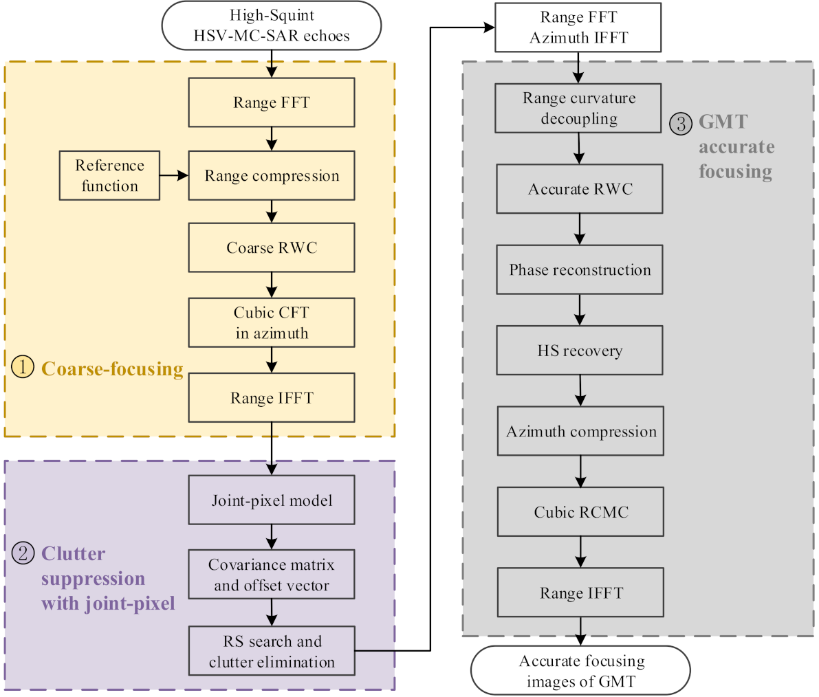
In this section, a robust clutter suppression and GMT imaging method for the high-squint HSV-MC-SAR is introduced in detail, and the flowchart summarized the processing steps as in Figure 2. (1) In the coarse-focusing stage, coarse range cell migration correction (RCMC), together with the Doppler compression are conducted. (2) The robust clutter suppression method with joint-pixel model retrieves precise RS, rejects the static clutter plus its ambiguous components, and effectively alleviates the unwanted GMT integration loss. (3) The derivation of GMT accurate-focusing is performed under a high-squint condition. Note that the three parts of the flowchart are correlated with Section 3.1Section 3.3.

3.1. Modified Coarse-Focusing of GMT and Clutter

In order to mitigate or minimize the impacts of RCM and GMT Doppler ambiguity, we describe here a modified coarse-focused method with cubic CFT for the GMT and clutter.
The echoes of GMT in the n -th channel can be defined as
S T 0 , n t ^ , t m = σ T a r t ^ τ n a a t m + Δ t n × exp j π γ t ^ τ n 2 exp j 2 π f c τ n
where τ n = 2 R n t m , R 0 / c represents the time-delay for the n -th channel, σ T is the GMT magnitude, t ^ indicates distance-time, and γ denotes the slope of linear frequency modulation (LFM) signal. a r · and a a · represent the window functions of range and azimuth in the time domain. λ and c reflect the transmitted carrier wavelength and propagation speed.
After the range Fourier transform (FT) and range compression, (3) is rewritten as
S T 1 , n f r , t m = σ T w r f r γ a a t m + Δ t n exp j 4 π c R n t m , R 0 f r + f c
where the range and carrier frequencies indicated by f r and f c , and the distance-envelope represented by w r · in the Doppler domain.
For the HSV-SAR, GMT speeds are far less than the platform speed, and the following relationships are approximated in the coarse-focusing stage.
v a _ r e l = v cos θ + v a v cos θ v r _ r e l = v sin θ + v r v sin θ Δ t n = d n d n v v x v v x d n d n v v
Substituting (2) and (5) into (4), we have
S T 2 , n f r , t m = σ T w r f r γ a a t m + Δ t n × exp j 4 π c f r + f c R 0 × exp j 4 π c f r + f c v sin θ t m + d n v × exp j 2 π c R 0 f r + f c v 2 cos 2 θ t m + d n v 2 × exp j 2 π c R 0 2 f r + f c v 3 sin θ cos 2 θ t m + d n v 3
It should be noted that the third, fourth, and fifth exponential terms in (6) are associated with range walk, range curvature, and cubic RCM terms, respectively. Note that the impacts of quadratic and cubic phases need to be calibrated, and the fourth-order phase can be disregarded that will be discussed later.
The coarse range walk correction (RWC) function can be derived from (6), and this yields
H r c m c , n f r , t m = exp j 4 π c v sin θ f r + f c t m exp j 4 π c v sin θ f r + f c d n v
The first and second phase terms situated on the right side of (7) can be employed to calibrate the range walk and channel phase errors. Multiplying (6) and (7), the range envelope alignment is basically achieved and yields
S T 3 , n f r , t m = σ T w r f r γ a a t m + Δ t n × exp j 4 π c f r + f c R 0 v r t m + d n v × exp j 2 π c R 0 f r + f c v 2 cos 2 θ t m + d n v 2 × exp j 2 π c R 0 2 f r + f c v 3 sin θ cos 2 θ t m + d n v 3
The HSV-SAR systems, with their severe Doppler broadening or ambiguity echoes, have difficulty in accurately indicate the GMTs. CFT, as an extension of FT, and with azimuth pulse compression capabilities, can mitigate or minimize the Doppler ambiguity that the traditional FT cannot [19]. However, the impact of high-order phase errors is inevitable for the high-squint HSV-MC-SAR due to its high maneuverability. Thus the second-order Taylor series of range history on which the traditional dechirp and CFT-based plus CFT-improved methods are based is no longer valid. By extending the second-order CFT [4,19] to the cubic CFT, the compression function in the n-th channel can be formulated as
H C F T , n f r , t m = H 2 f r , t m H 3 f r , t m exp 2 π f a t m }
with
H 2 f r , t m = exp j 2 π c R 0 f r + f c v 2 cos 2 θ t m + d n v 2 H 3 f r , t m = exp j 2 π c R 0 2 f r + f c v 3 sin θ cos 2 θ t m + d n v 3
To alleviate the RCM and GMT Doppler ambiguity impacts, the coarse-focusing processors can be expressed as
S T 4 , n f r , f a = S T 3 , n f r , t m H C F T , n f r , t m d t m = σ T w r f r γ G a z w a f a f d × exp j 4 π c f r + f c R 0 × exp j 2 π f a + 2 f d d n v
where w a · represents the azimuth-envelope in the Doppler domain. G a z is the signal magnitude after azimuth accumulation, f a reflects the azimuth CFT frequency, and f d = 2 v r f r + f c / c . Inspecting (11), we can find that the cubic CFT simultaneously compresses the echoes in azimuth, compensates the cubic RCM, and calibrates the envelope offset brought by the channel errors.
Then, after the range inverse FT (IFT), the coarse-focused GMT signal in the n-th channel can be obtained as
S T 5 , n t ^ , f a = σ T G r G a z a r t ^ 2 R 0 c w a f a + f d c × exp j 4 π λ R 0 exp j 2 π ( f a + 2 f d c ) d n v
where G r denotes the signal magnitude after range accumulation, and f d c = 2 v r / λ indicates the Doppler center of GMT.
The Doppler ambiguity number can be defined as B a / PRF = 2 L + 1 , and PRF represents the pulse repetition frequency. the original Doppler spectrum is divided into 2 L + 1 ambiguity areas, and B a indicates the azimuth Doppler bandwidth. L is a positive integer, and l L , L . The GMT Doppler center and the CFT frequency spectrum both have Doppler ambiguity, and the ambiguity number of Doppler center defined as
K d c = f d c PRF 0.5
where · reflects the ceiling operator.
According to the Doppler spectrum diagram [47], baseband frequency is given by
f b = f a l · PRF [ PRF / 2 , PRF / 2 ]
For a baseband signal, RS and Doppler center of GMT can be calculated by
v r _ b = f d c _ b · λ 2 = v r K d c · v PRF v PRF 2 , v PRF 2
f d c _ b = f d c K d c · PRF [ P R F / 2 , P R F / 2 ]
where v PRF = PRF · λ / 2 reflects the first blind speed.
Assuming that a GMT is located in the l-th ambiguity area, the coarsely focused imagery of GMT for the Nyquist band is formulated as
S T , n t ^ , f b = l = L L σ T G r G a z a r t ^ 2 R 0 c × w a f b + f d c _ b + l + K d c · PRF × exp j 4 π λ R 0 × exp j 2 π f b + l · PRF + 2 f d c d n v
One notices that only the last exponential term contains the space information of channel, and the steering vector of GMT can hence be defined as
a T , l v r = exp j 2 π f b + l · PRF + 4 v r / λ d 2 v exp j 2 π f b + l · PRF + 4 v r / λ d n v exp j 2 π f b + l · PRF + 4 v r / λ d N v
Zeroing the GMT speeds in (17), the expression of coarsely focused clutter imagery is retrieved and we define
S C , n t ^ , f b = l = L L σ T G r G a z a r t ^ 2 R 0 c w a f b + l · PRF × exp j 2 π f b + l · PRF d n v exp j 4 π λ R 0
Similarly, the steering vector of stationary clutter can be written as
a C , l = exp j 2 π f b + l · PRF d 2 v exp j 2 π f b + l · PRF d n v exp j 2 π f b + l · PRF d N v
From (17) and (19), one can see that clutter plus its ambiguous components are located in same channel. In fact, only few GMTs are located in covering areas and coarsely-focused GMTs are sparse in the surrounding stationary clutter, and thus the Doppler ambiguity impact of GMT has been mitigated [48]. Besides, it is necessary to reject the clutter Doppler ambiguity to indicate the GMT, this will be discussed in detail below.

3.2. Robust Clutter Suppression Method with Joint-Pixel Model

In order to recover the RS so as to achieve a satisfactory quality of beam-former and extract the GMT from the Doppler ambiguity echoes, a robust clutter suppression method which modifies the beam-former through precise RS recovery, eliminates the clutter plus its ambiguous components and maintains the GMT profiles is next introduced.
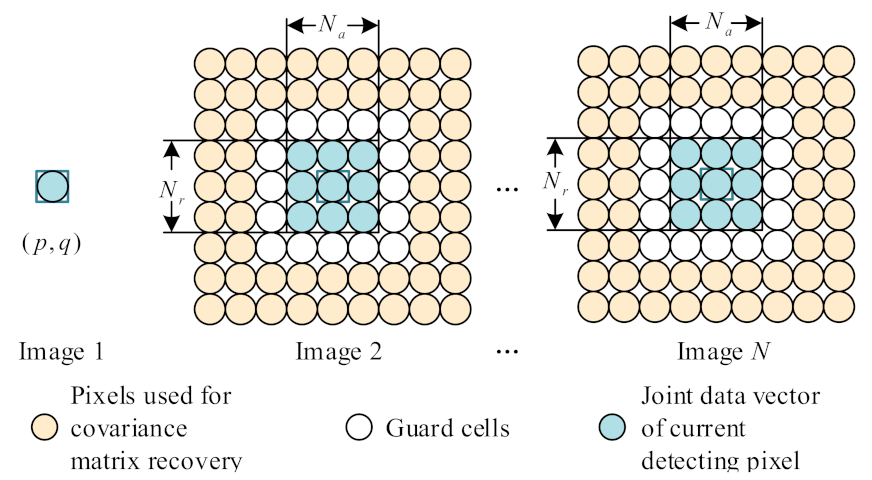
Here, we utilize the joint-pixel model to effectively retrieve RS and eliminate clutter, especially when the co-registration error and channel phase mismatch exist [44,49]. Figure 3 provides the joint-pixel model for the coarsely focused imagery. For the channel 1, image 1 with single-pixel model is given by
Z p , q = S T , 1 p , q + S C , 1 p , q
The joint-pixel model is conducted for motion parameter recovery, which is implemented through the detected and adjacent pixels of coarsely focused imagery, and the hypotheses can be defined as follow
S = S T + S C
Inspecting (22), the GMT and clutter signals of coarsely focused imagery with joint-pixel model can be formulated as
S T = S T , 1 p , q , , S T , n p , q , , S T , N p , q T C N C × 1
S C = S C , 1 p , q , , S C , n p , q , , S C , N p , q T C N C × 1
where
S T , n p , q = S T , n p N r 1 / 2 , q N a 1 / 2 , , S T , n p + N r 1 / 2 , q + N a 1 / 2 C 1 × N r · N a
S C , n p , q = S C , n p N r 1 / 2 , q N a 1 / 2 , , S C , n p + N r 1 / 2 , q + N a 1 / 2 C 1 × N r · N a
N a and N r ( N a = N r = 3 ) indicate the unit number in the azimuth and range directions of the selected window, p and q denote the range and azimuth pixels, · T indicates transpose operator, and N C = N r · N a ( N 1 ) + 1 represents pixel number of a joint-pixel data.
The covariance matrix based on joint-pixel model and pixel offset vector [45] are formulated as
R JP = E [ S k H S k k = 1 , 2 , , N JP ] × 1 N JP k = 1 N JP SS k H / S k H S k C N C × N C
A = 1 , ξ 1 e j φ 1 ξ N C 1 e j φ N C 1 T C N C × 1
where N JP is the sample number of joint pixel, and N JP 2 N C 1 . E [ · ] and [ · ] H indicate the mean and conjugate transpose operators. ξ τ e j φ τ τ = 1 , 2 , . . . , N C 1 denotes the signal offset between the auxiliary and reference channels, which are affected by the co-registration or channel phase errors.
After that, using optimal pixel offset vector in (27) to alleviate GMT steering vector [45,50], yielding
a T , l opt v r = A a ^ T , l v r C N C × 1
where a ^ T , l v r = [ 1 , a T , l v r ones N r · N a , 1 ] , ⊙ and ⊗ reflect the Hadamard and Kronecker operators.
The general beam-forming [51] of clutter suppression is expressed as
min W W H R JP W s . t . W H B = Q
where B = a T , l opt v r , a ^ C , L , , a ^ C , l , , a ^ C , L represents the constrained matrix, a ^ C , l = [ 1 , a C , l ones N r · N a , 1 ] , and Q = 1 , 0 , 0 , , 0 H C 1 × 2 L + 1 is the column vector. W denotes the weight vector, which is used for extracting the GMT from the coarsely focused imagery.
Inspecting (30), the expression of weight vector can be given by
W ^ = R JP 1 B B H R JP 1 B 1 Q
where [ · ] 1 reflects the inverse operator.
Thereby, the RS search has the following form
v ^ r , W ^ opt = arg max v r W ^ H Z p t , q t 2 W ^ H R JP W ^ Q
where v ^ r 0 denotes the precise RS, which corresponds to the unambiguity area l ^ of GMT, W ^ opt reflects the optimal weight vector.
Finally, the results of clutter suppression can be expressed as follows
S T 0 = W ^ opt H · Z
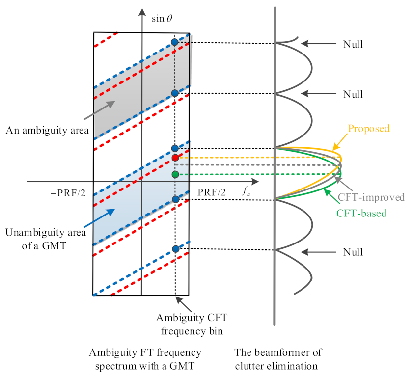
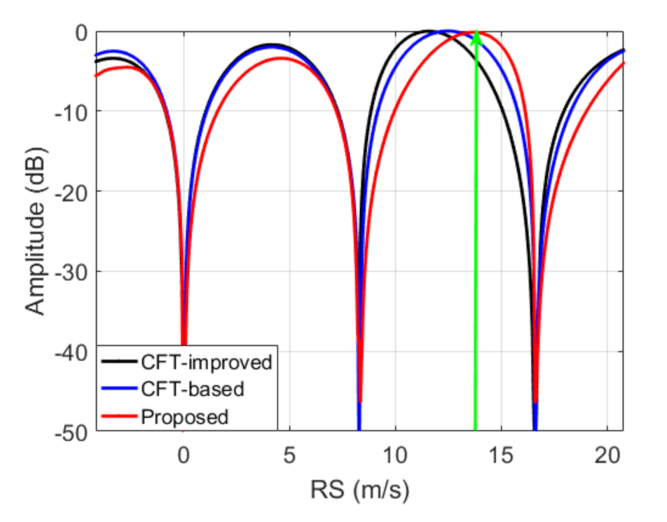
Figure 4 shows the beam-former of clutter cancellation for different methods, where the red and blue lines represent the ambiguous Doppler spectrums of GMT and clutter, and the profiles are shown by red and blue dots. To be specific, the CFT-based method [19] assumes that the beam-former is aligned to the middle of unambiguous area (e.g., corresponding to the green dot), which should consider the impacts caused by the beam-former mismatch. The CFT-improved method [4] which retrieves a rough RS via a large interval retrieval, relieves the beam-former mismatch, but the unwanted integration loss in a desired GMT direction still exists to vary degrees. In contrast, the beam-former center of the proposed method matches a GMT, which means that the unwanted integration loss can be excellently avoided.
The RS recovery can be divided into two steps:
  • The RS is estimated in [ v PRF / 2 , v PRF / 2 ] , an arbitrary RS component v r 0 is obtained;
  • Performing the RS search in { U [ v r 0 L · v PRF ] , , U [ v r 0 ] , , U [ v r 0 + L · v PRF ] } , the precise RS and GMT unambiguity area can be recovered. Note that U [ · ] reflects the neighborhood.

3.3. GMT Accurate-Focusing

After the above processes, the ambiguity-free GMT, together with the precise RS, can be retrieved. In this subsection, we propose an accurate GMT imaging method for the high-squint HSV-MC-SAR, which estimates HS and inhibits the HS and RS impacts. Compared with the CFT-improved method, the proposed imaging method has fewer steps, preprocessing the RS retrieval and simplifying the first-order phase correction.
After range FT and azimuth IFT were accomplished, the GMT signal can be formulated as
S T 1 f r , t m = w r f r a a t m t c Φ f r , t m = w r f r a a t m t c × exp j 4 π v r f r + f c c t m t 0 × exp j 2 π v a v a 2 v cos θ f r + f c c R 0 t m t 0 2 × exp j 4 π f r + f c c χ t m t 0 3 × exp j 4 π f r + f c c R 0
where
Φ f r , t m = 4 π f r + f c c α t m t 0 + β t m t 0 2 + χ t m t 0 3 + φ
α = v r + v cos θ v a 2 R 0 t 0 t c 3 v r v cos θ v a 2 2 R 0 2 t 0 t c 2 v r
β = v a 2 v cos θ v a 2 R 0 3 v r v cos θ v a 2 2 R 0 2 t 0 t c v a v a 2 v cos θ 2 R 0
χ = sin θ v a 2 v r cos θ v a v + cos θ cos θ v r 2 sin θ v a v 2 2 R 0 2
φ = 4 π f r + f c c R 0 4 π f r + f c c v r t 0 t c 2 π f r + f c v cos θ v a 2 c R 0 t 0 t c 2 + 2 π v r v cos θ v a 2 f r + f c c R 0 2 t 0 t c 3 4 π f r + f c c R 0
where t 0 and t c denote arbitrary azimuth-time and synthetic aperture center time. A HSV-MC-SAR exhibits a speed advantage compared to the air-borne SAR. The arbitrary azimuth-time is close to the synthetic aperture center time, and, thus, the derivation of (34) are valid.
To decouple the f r and t m 2 , the second-order keystone transform (SOKT) [4,52,53] has proven to be a reliable tool, and it can be expressed as
t m t 0 = f c f r + f c 0.5 t ˜ m t 0
where t ˜ m is called new azimuth-time after keystone transform.
Substituting (40) into (34), it yields
S T 2 f r , t ˜ m = w r f r a a t ˜ m t c × exp j 4 π v r f c f r + f c 0.5 c t ˜ m t 0 × exp j 2 π f c v a v a 2 v cos θ c R 0 t ˜ m t 0 2 × exp j 4 π f c c f c f r + f c 0.5 χ t ˜ m t 0 3 × exp j 4 π f r + f c c R 0
Clearly, f r f c is valid, and the approximate formulation can hence be obtained as
f c f r + f c 0.5 f c + f r / 2 f c f r + f c 0.5 1 f r 2 f c
Applying (42) in (41), we have
S T 3 f r , t ˜ m = w r f r a a t ˜ m t c × exp j 4 π v r f c + f r / 2 c t ˜ m t 0 × exp j 2 π f c v a v a 2 v cos θ c R 0 t ˜ m t 0 2 × exp j 4 π f c c 1 f r 2 f c χ t ˜ m t 0 3 × exp j 4 π f r + f c c R 0
Obviously, the decoupling of f r and t ˜ m is achieved. By using the precise RS to revise the RWC function, its accurate expression can be generated.
H 1 ( f r , t ˜ m ) = exp j 4 π v ^ r f c + f r / 2 c t ˜ m t 0
After an accurate RWC was performed, the echo signal can be expressed as follows
S T 4 f r , t ˜ m = w r f r a a t ˜ m t c × exp j 2 π f c v a v a 2 v cos θ c R 0 t ˜ m t 0 2 × exp j 4 π f c c 1 f r 2 f c χ t ˜ m t 0 3 × exp j 4 π f r + f c c R 0
To recover the HS, the phase reconstruction processors are derived as
S T 5 f r , t ˜ m = S T 4 f r , t ˜ m H 2 f r , t ˜ m = w r f r a a t ˜ m t c × exp j 2 π f c v a v cos θ 2 c R 0 t ˜ m t 2 × exp j 4 π f c c 1 f r 2 f c χ t ˜ m t 3 × exp j 4 π f r + f c c R 0
where
H 2 f r , t ˜ m = exp j 2 π f c v 2 cos 2 θ c R 0 t ˜ m t 0 2
After range IFT, viz.,
S T 6 t ^ , t ˜ m = a r t ^ v r v a 2 2 c R 0 2 t ˜ m t 0 3 2 R 0 c a a t ˜ m t c × exp j 2 π f c v a v cos θ 2 c R 0 t ˜ m t 0 2 × exp j 4 π f c c χ t ˜ m t 0 3 × exp j 4 π f r + f c c R 0
The simplified fractional Fourier transform (SFrFT) is a reliable way for HS recovery, especially when the impact of Doppler ambiguity is mitigated [54,55]. We apply the SFrFT processors and yield
χ ρ η = + S T 6 t ^ , t ˜ m · Γ ρ t ˜ m , η d t ˜ m
where Γ ρ t ˜ m , η = exp j η t ˜ m / 2 sin ρ denotes the kernel function [56]. The rotation-angle operator denoted by is estimated by searching the maximum output of the following formulation [57], that is,
ρ e = arg max ρ , η χ ρ η 2
Then, the HS calculation can be conducted as follows:
v ^ a = c R 0 2 f c γ e s t
where γ e s t = PRF 2 cot ρ e / N n a n reflects the Doppler rate, and N n a n indicates the number of processing data in azimuth.
To achieve the accurate focusing, the second-order azimuth compression function and the correction function of cubic RCM are constructed from the recovered values of GMT’s motion parameters, we have
H a t ^ , f ˜ a = exp j π c R 0 2 f c v ^ a v cos θ 2 f ˜ a 2
H 3 f r , t ˜ m = exp j 4 π f c c 1 f r 2 f c χ t ˜ m t 0 3
where f ˜ a indicates the new Doppler frequency for t ˜ m .
After applying the azimuth compression and cubic RCMC, the accurately-focused of GMT in the 2-D time domains can be expressed as
S T 7 t ^ , t ˜ m = σ ^ T sinc B t ^ 2 R 0 c sinc t ˜ m t c exp j 4 π f c c R 0
where σ ^ T illustrates the magnitude of accurate-focused GMT.

4. RCM Analysis

Here, the RCM impacts of HSV-SAR for different platform speeds or squint angles are discussed in detail.

4.1. Range Walk and Range Curvature

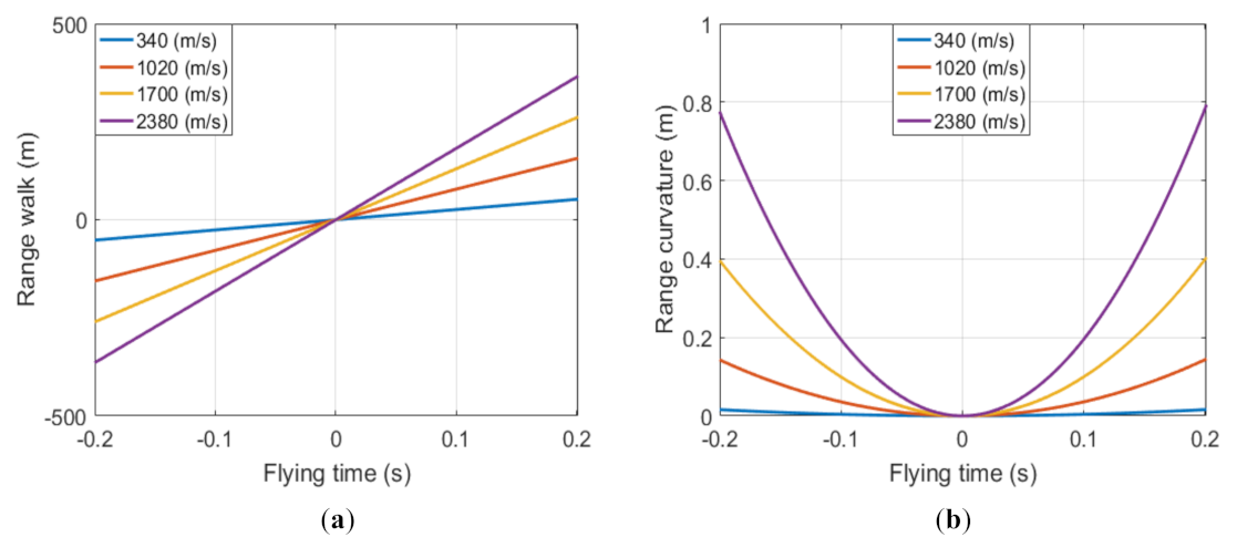
Figure 5 and Figure 6 show the simulation results of RCM for different squint angles or platform speeds, where simulation experiments are conducted with specific parameters listed in Table 1. It can be seen from Figure 5a and Figure 6a that with the increase in the squint angles or platform speeds, the range walk becomes larger. In Figure 5b, as the squint angle increases, the range curvature decreases. In the case of θ = 50 ° , the range walk is much greater than one range resolution unit, and the range curvature is less than 1 m. Thereby, the coarse RWC can be performed without considering the range curvature effect.
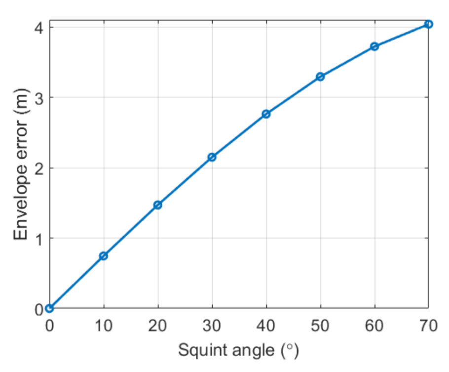
For the HSV, taking the platform speed v = 2380 m/s, for example, the relationship between the neighboring channel errors and squint angles is as illustrated in Figure 7. In the high-squint mode, the envelope error of neighboring channel after range compression has exceeded three range resolution units. To calibrate the imagery, it is necessary to compensate the channel errors.

4.2. High-Order Phases

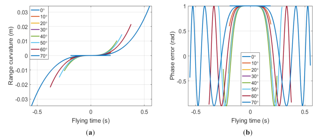
With the simulation parameters in Table 1 and the platform speed v = 2380 m/s, the high-order phases for different squint angles are summarized in Figure 8 and Figure 9. The spatial variations of cubic RCM are shown in Figure 8a. Additionally, for a squint angle over 45 ° , the cubic RCM has exceeded one hundredth of azimuth resolution, and its cubic phase error in azimuth more than 1 rad as shown in Figure 8b. From Figure 9, the phase errors of fourth-order are less than π / 4 in a high-squint case, and its impact on focusing quality is negligible and may be ignored. Therefore, in a high-squint HSV-SAR mode, the third-order Taylor expansions of instantaneous range history can satisfy the accuracy of high-resolution imagery.

5. Simulation and Examples

5.1. Simulation Results

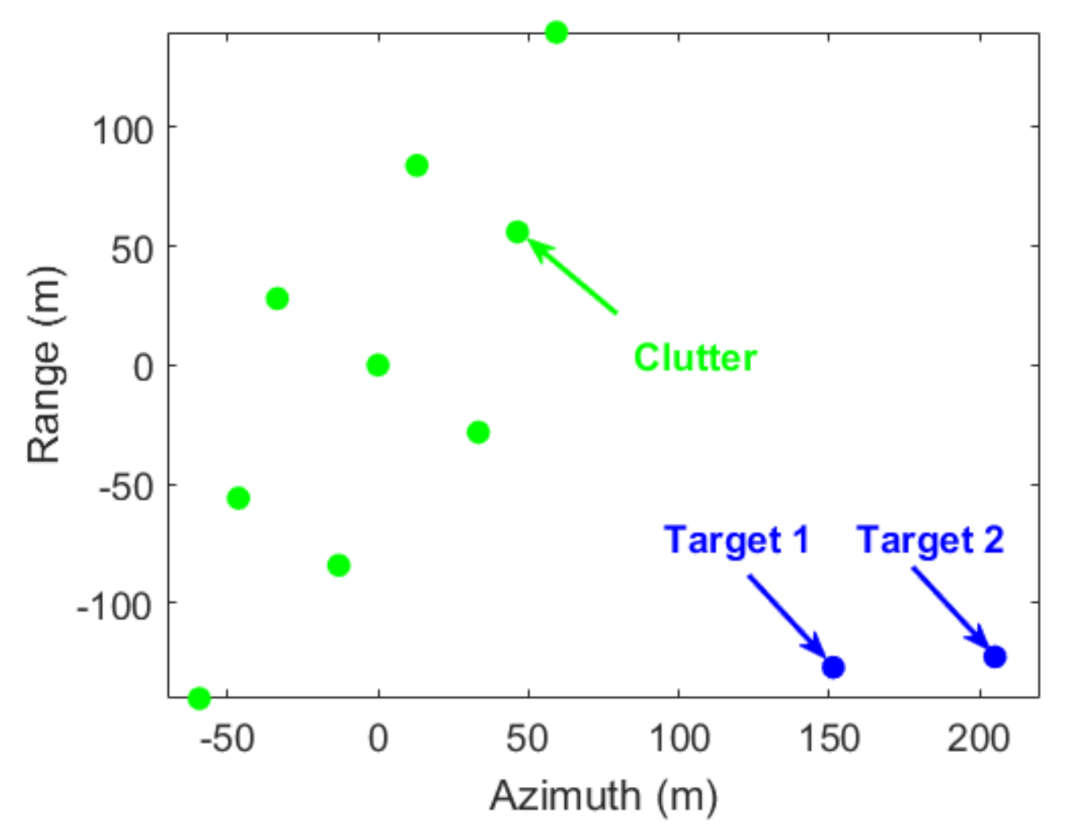
In this section, the proposed method was demonstrated to be effective on clutter suppression and GMT imaging in simulation data of high-squint HSV-MC-SAR, where the specific parameters of simulation examples are listed in Table 2. The distribution diagram of point scatterers are sketched in Figure 10, and the signal-to-clutter ratio (SCR) and signal-to-noise ratio (SNR) were preset to be 0 and 10 dB, respectively. Additionally, for the first GMT, HS and RS are noted to be 0 and 14 m/s, and the 2-D motion parameters of second GMT were both set at v a = v r = 14 m/s.
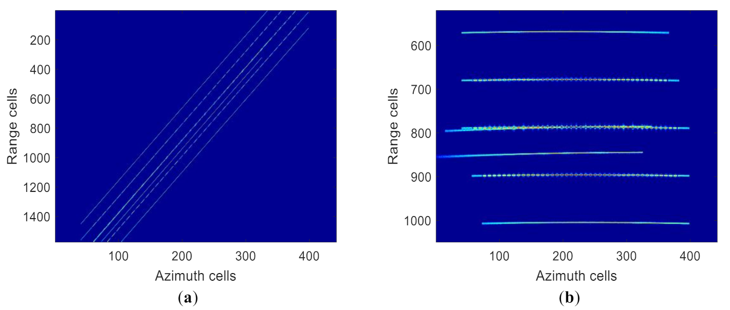
First, the processing results of two GMTs plus clutter are summarized in Figure 11. Figure 11a illustrates the range compression results without coarse RWC, one notices that these profiles are severely oblique, which indicates that the effect of range walk is not calibrated. The processing results after coarse RWC are shown in Figure 11b, and the profiles of two GMTs and clutter are both roughly aligned.
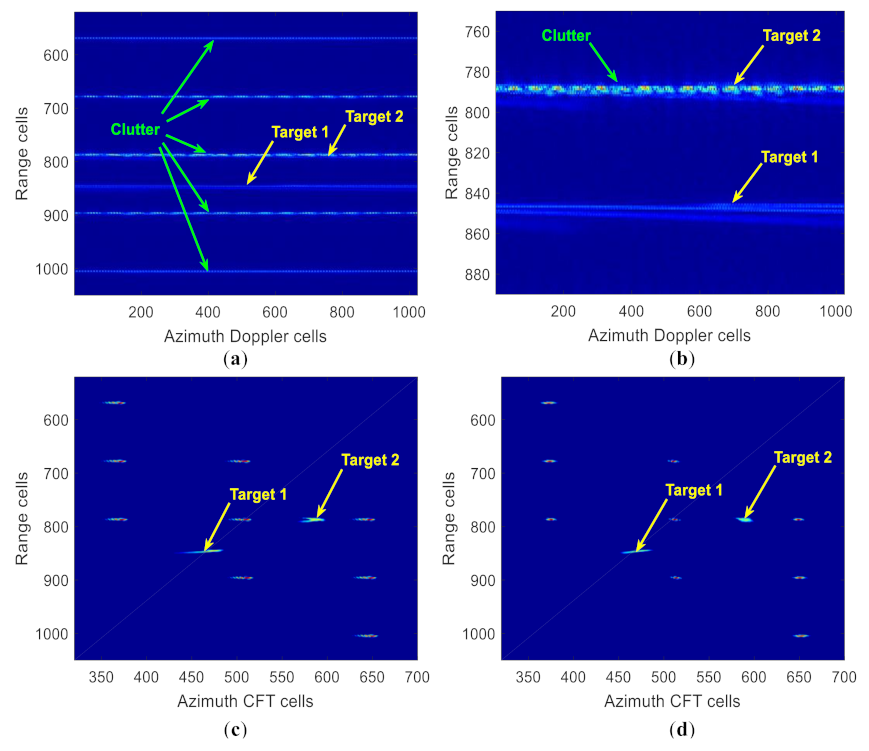
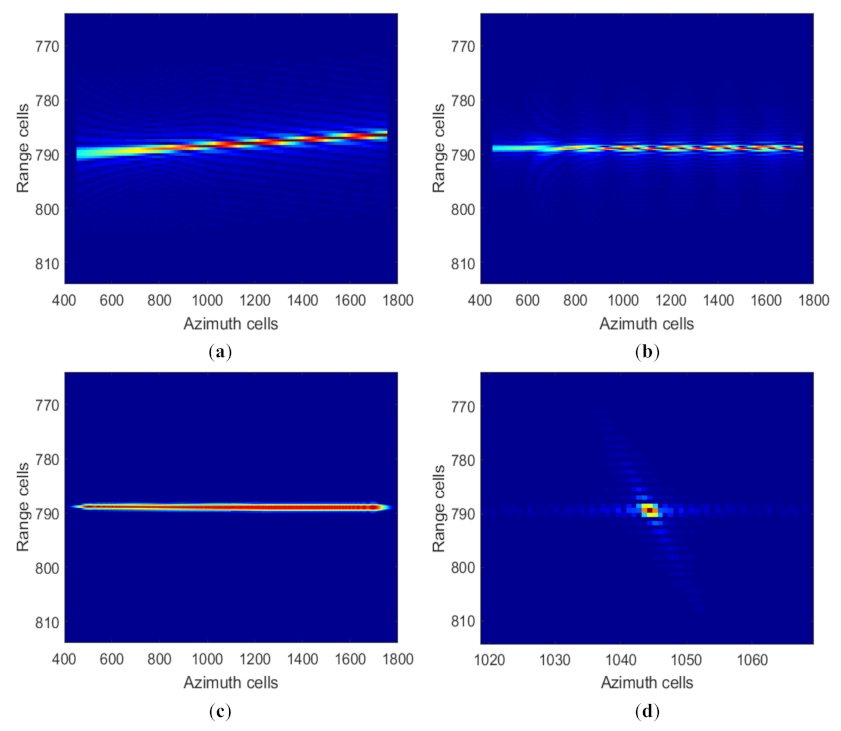
After that, the signal processing results of two GMTs and some clutter in the range compression and azimuth Doppler frequency domain are summarized in Figure 12. From Figure 12a, the point scatterer profiles after azimuth FT are shown first, and the local enlarge results are illustrated in Figure 12b. We notice that the profile aliasing of two GMTs exists, and the profiles of first GMT and clutter are garbled. The classical FT operation, due to that the phenomenon of Doppler ambiguity is present and GMT trajectory are submerged in the surrounding stationary clutter, brings tremendous challenge to the subsequent clutter suppression and GMT imaging. Figure 12c illustrates the profiles of point scatterers after azimuth second-order CFT operation [4,19], where we can see that two GMTs are now separated from the surrounding stationary clutter. By using the operation to compress the Doppler spectrum, the smeared coarsely-focused imagery of two GMTs and clutter is recovered. Because the second-order CFT would suffer from quality degradation in a high-squint case without high-order RCMC. After cubic CFT in azimuth, the coarsely focused imagery of two GMTs and clutter as shown in Figure 12d. One notices that the smeared imagery of two GMTs does not occur, which means the impacts of Doppler ambiguity and RCM are alleviated.
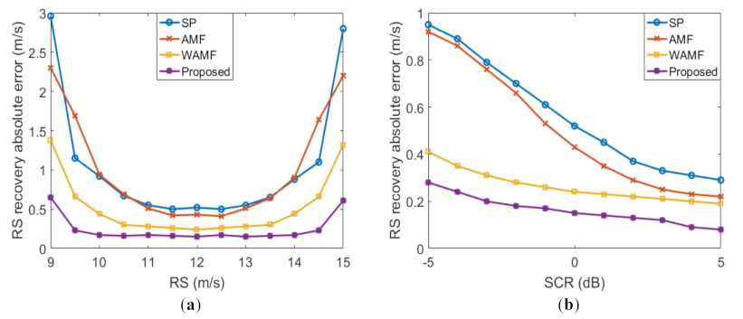
Next, Figure 13a shows the quality assessment results of RS recovery with respect to RS from 9 to 15 m/s. We notice that the proposed RS recovery method yields somewhat smaller absolute error as compared to the other methods. The performance of the AMF and SP methods declines when the co-registration and channel phase errors are involved. The WAMF method, due to the power heterogeneous sample pixels, suffers from performance loss of RS recovery [45]. With the searching that maximizes the magnitude, the parameter recovery quality will decrease, even when RS approaches an integer multiple of the first blind speed (a GMT and clutter in close Doppler frequency unit). In v r = 12 m / s case, the absolute errors of RS recovery for different SCR are summarized in Figure 13b. One notices that as the SCR increases, the absolute errors of parameter recovery become smaller.
For the different clutter suppression methods, the magnitude of beam-former is plotted as a function of the RS, as shown in Figure 14, where the green arrow reflects real RS direction. One notice that the proposed method outperforms the other two methods in the desired GMT direction, and the quality of GMT integration is remarkably increased. The reason is that the RS is unknown in clutter suppression stage for the CFT-based and CFT-improved methods, which induces a mismatch between the beam-former center and GMT, whereas the beam-former of the proposed method is optimized by precise RS.
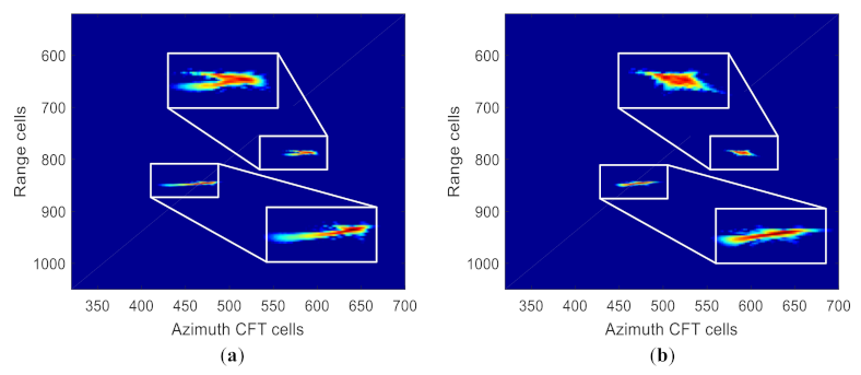
After clutter suppression, the results as summarized in Figure 15, and the enlarged view of the GMT envelopes corresponds to the white rectangle. Figure 15a shows the GMT profiles after second-order CFT and robust clutter suppression, we notice that the envelopes of two GMTs are distorted, due to the presence of cubic phase errors. Figure 15b illustrates the GMT extraction results of our proposed method, one notices that the GMT profiles can be recovered extremely well, because the coarse RCMC is conducted before clutter suppression and an accurate beam-former is formed.
Then, the accurate focusing processors of second GMT as summarized in Figure 16. The responses in the 2-D time domain are shown in Figure 16a, and the profiles is seen to be misaligned. Figure 16b,c show the processing results after decoupling and accurate RWC, one notices that second GMT profiles is satisfactory aligned. To aid further rejection of the GMT sidelobe, we correct the cubic RCM and finally yield the point-like GMT, the accurate-focused imagery as illustrated in Figure 16d.
Furthermore, Figure 17 shows the imagery quality assessment of second GMT after accurate focusing. From Figure 17b,c, the peak sidelobe ratio (PSLR), whose ideal value of −13.27 dB, are seen to be −13.17 and −13.20 dB, in azimuth and range, respectively. The integrated sidelobe ratio (ISLR) of azimuth and range are increased by 0.16 and 0.09 dB compared to its ideal value of −10.24 dB [58]. Therefore, the proposed GMT accurate-focused method is capable of producing the satisfactory imagery results, and its effectiveness has been demonstrated.
To assess the performance for ISTAP and CFT plus its modified methods, the primary quality assessment indexes are summarized in Table 3. Among the four methods above, the proposed method produces the highest SCNR, precise GMT 2-D speeds, and in comparatively short calculation time. Note that the results in Table 3 are the averages of 500 Monte-Carlo experiments tested on a personal PC with intel i7 [email protected] GHz and 16 GB RAM, the codes are run by MATLAB 2016a.
Further observations from Table 3 include the followings: First, the SCNR of the proposed method outperforms the other three methods. To be specific, the ISTAP method, due to that the radar system parameters used in this simulation cannot provide sufficient DOF, and, thus, is unable to effectively carry out GMT integration. On the other hand, during clutter suppression, the CFT-based method assumes that RS is half the first blind speed, and that the coarse RS of the CFT-improved method is obtained through the large interval retrieval. Therefore, the CFT-based and CFT-improved methods suffer from the problems of beam-former mismatch and unwanted integration loss.
Second, for the proposed method, the absolute error of GMT 2-D speeds is relatively small compared to the other methods. The reason is that the performance of motion parameter recovery is sensitive to SCNR and the proposed method is able to achieve the highest SCNR among all methods. Moreover, GMT parameter recovery accuracy of the CFT-improved method is slightly inferior, because it takes the finer retrieval of GMT 2-D speeds during GMT accurate-focusing and exhibits a higher false alarm probability [59].
Finally, the calculation times of the proposed and the other methods are quantified. In the clutter suppression step, the computation complexity of the ISTAP method is N n r N n a × O N s r N s a 3 N 3 , where N s a and N s r represent the sampling number of simulation data in the azimuth and range directions, the searching numbers of HS and RS are denoted by N n a and N n r . The computation complexities of the other three methods are both O N s r N s a 3 N 3 . During the GMT focusing, the precise RS recovery of CFT-improved method burdens the radar systems, since it adds N s r N s a 2 multiplications and N s r N s a 1 additions. For all the above algorithms, the computation complexities of clutter suppression are much greater than that of GMT focusing, and, thus, the calculation times of the ISTAP method is the highest. Since the RS estimation is preprocessed and the RWC is simplified, the proposed method consumes less computation time than the CFT-improved method. Although the computation complexity of our proposed method is not better than that of the CFT-based method, the recovery of the GMT speeds is better and the results of GMT imaging is also better in a high-squint case.

5.2. Real Data Results

Here, the proposed method was verified to be effective in relocation of real measured data. The parameters of the SAR systems are shown in Table 4. The targets are vehicles driving on a road in the coverage region, the distribution diagram of the scene is as shown in Figure 18 [50].
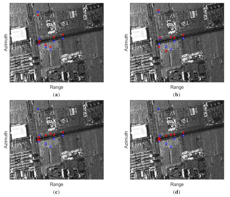
Figure 19 summarizes the relocation results of four different methods, where the blue and red circles represent the location and relocation positions of the moving targets. In Figure 19a,b, the relocation results show that most of the moving targets are not on the road. The reason is that the phenomenon of co-registration and channel phase errors occur, resulting in the failure of AMF and SP methods. In contrast, from the relocation positions of WAMF and our proposed methods as illustrated in Figure 19c,d, one notices that the moving targets are indicated on or beside the road. More importantly, the proposed method, which calibrates the impact of 2-D spends during GMT accurate-focusing, has a better relocation results compared to the WAMF method.

6. Conclusions

The existing GMT indication studies for SAR are usually based on air-borne or space-borne systems, while most researches of HSV-SAR GMT indication work in a side-looking or single-channel squint-looking mode. This paper explores a robust clutter suppression and GMT imaging method for the high-squint HSV-MC-SAR. These problems (high-order phase error, motion parameter coupling, Doppler ambiguity, antenna size limitations) brought by the high-speed and high-squint are analyzed and solved, and the mismatch between the beam-former and GMT is also minimized. At first, the RCM impact is analyzed and corrected, and the point scatterers are coarsely focused. Then, robust clutter suppression method based on joint-pixel model is proposed, which has the ability to eliminate the static clutter plus its ambiguous components and mitigate the unwanted GMT integration loss. Finally, accurately-focused GMT imagery is obtained under a high-squint condition. Compared to the existing methods, the proposed method has the highest SCNR and motion parameter recovery accuracy, and requires shorter calculation times.
Future works include extending the method in this article to GMT location, and skipping trajectory should be considered to improve this method and enhance the ability to adapt to more complex flight trajectories.

Author Contributions

J.H. and Y.C. and developed the theory and signal model. J.H. and T.-S.Y. performed and analyzed the numerical simulations. J.H. and F.W. wrote and edited the paper. All authors have read and agreed to the published version of the manuscript.

Funding

This work was funded by the National Nature Science Foundation of China under Grant 61771367, and in part by the Science and Technology on Communication Networks Laboratory under Grant HHS19641X003, as well as in part by the 111 Project under Grant B18039.

Data Availability Statement

The data presented in this study are available on request from the corresponding author.

Conflicts of Interest

The authors declare no conflict of interest.

References

  1. Chen, H.; Cheng, X.; Dai, C.; Liu, F. Robust stability analysis of H1-SGQKF and its application to transfer alignment. Signal Process. 2015, 117, 310–321. [Google Scholar] [CrossRef]
  2. Wang, W. Near-space vehicle-borne SAR with reflection-antenna for high-resolution and wide-swath remote sensing. IEEE Trans. Geosci. Remote Sens. 2012, 50, 338–348. [Google Scholar] [CrossRef]
  3. Tang, S.; Guo, P.; Zhang, L.; So, H.C. Focusing Hypersonic Vehicle-Borne SAR Data Using Radius/Angle Algorithm. IEEE Trans. Geosci. Remote Sens. 2020, 58, 281–293. [Google Scholar] [CrossRef]
  4. Wang, Y.; Cao, Y.; Wang, S.; Su, H. Clutter Suppression and Ground Moving Target Imaging Approach for Hypersonic Vehicle borne multichannel radar based on Two-Step focusing Method. Digit. Signal Process. 2019, 85, 62–76. [Google Scholar] [CrossRef]
  5. Wang, Y.; Cao, Y.; Peng, Z.; Su, H. Clutter suppression and moving target imaging approach for multichannel hypersonic vehicle borne radar. Digit. Signal Process. 2017, 68, 81–92. [Google Scholar] [CrossRef]
  6. Chen, Z.; Zhou, Y.; Zhang, L.; Lin, C.; Huang, Y.; Tang, S. Ground Moving Target Imaging and Analysis for Near-Space Hypersonic Vehicle-Borne Synthetic Aperture Radar System with Squint Angle. Remote Sens. 2018, 10, 1966. [Google Scholar] [CrossRef] [Green Version]
  7. Galletti, M.; Krieger, G.; Thomas, B.; Marquart, M.; Johannes, S.S. Concept design of a near-space radar for tsunami detection. In Proceedings of the IEEE International Geoscience and Remote Sensing Symposium, Barcelona, Spain, 23–28 July 2007; pp. 34–37. [Google Scholar]
  8. Khedkar, S.B.; Kasav, S.M.; Khedkar, A.S.; Mahajan, S.M.; Satpute, D.R. A Review on Hypersonic Aircraft. Int. J. Adv. Technol. Eng. Sci. 2015, 3, 1566–1570. [Google Scholar]
  9. Xu, X.; Liao, G.; Yang, Z.; Wang, C. Moving-in-pulse duration model-based target integration method for HSV-borne high-resolution radar. Digit. Signal Process. 2017, 68, 31–43. [Google Scholar] [CrossRef]
  10. Zhang, S.; Xing, M. A Novel Doppler Chirp Rate and Baseline Estimation Approach in the Time Domain Based on Weighted Local Maximum-Likelihood for an MC-HRWS SAR System. IEEE Trans. Geosci. Remote Sens. Lett. 2017, 14, 299–303. [Google Scholar] [CrossRef]
  11. Xu, J.; Huang, Z.; Wang, Z.; Xiao, L.; Xia, X.; Long, T. Radial Velocity Retrieval for Multichannel SAR Moving Targets with Time–Space Doppler Deambiguity. IEEE Trans. Geosci. Remote Sens. 2018, 56, 35–48. [Google Scholar] [CrossRef]
  12. Lv, G.; Li, Y.; Wang, G.; Zhang, Y. Ground Moving Target Indication in SAR Images with Symmetric Doppler Views. IEEE Trans. Geosci. Remote Sens. 2016, 54, 533–543. [Google Scholar] [CrossRef]
  13. Huang, Y.; Liao, G.; Xu, J.; Yang, D. MIMO SAR OFDM chirp waveform design and GMTI with RPCA based method. Digit. Signal Process. 2016, 51, 184–195. [Google Scholar] [CrossRef]
  14. Yang, J.; Liu, C.; Wang, Y. Imaging and parameter estimation of fast-moving targets with signle-antenna SAR. IEEE Trans. Geosci. Remote Sens. Lett. 2014, 11, 529–533. [Google Scholar] [CrossRef]
  15. Robinson, P.N. Depth of field for SAR with aircraft acceleration. IEEE Trans. Aerosp. Electron. Syst. 1984, 20, 603–616. [Google Scholar] [CrossRef]
  16. Tang, S.; Zhang, L.; Hing, S. Focusing High-Resolution Highly-Squinted Airborne SAR Data with Maneuvers. Remote Sens. 2018, 10, 862. [Google Scholar] [CrossRef] [Green Version]
  17. Jing, K.; Xu, I.; Yao, D.; Huang, Z.; Long, T. SAR Ground Moving Target Indication via Cross-Track Interferometry for a Forward-Looking Array. IEEE Trans. Aerosp. Electron. Syst. 2017, 53, 966–986. [Google Scholar] [CrossRef]
  18. Tang, S.; Zhang, L.; Guo, P.; Liu, G.; Zhang, Y.; Li, Q.; Gu, Y.; Lin, C. Processing of monostatic SAR with general configurations. IEEE Trans. Geosci. Remote Sens. 2015, 53, 6529–6546. [Google Scholar] [CrossRef]
  19. Zhang, S.; Xing, M.; Xia, X. Robust clutter suppression and moving target imaging approach for multichannel in azimuth high-resolution and wide-swath synthetic aperture radar. IEEE Trans. Geosci. Remote Sens. 2015, 53, 687–709. [Google Scholar] [CrossRef]
  20. Cumming, I.G.; Wong, F.H. Digital Processing of Synthetic Aperture Radar Data: Algorithm and Implementation; Artech House: Norwood, MA, USA, 2005. [Google Scholar]
  21. Huang, Y.; Liao, G.; Xu, J.; Li, J.; Yang, D. GMTI and Parameter Estimation for MIMO SAR System via Fast Interferometry RPCA Method. IEEE Trans. Geosci. Remote Sens. 2018, 56, 1174–1187. [Google Scholar] [CrossRef]
  22. Wang, Y.; Cao, Y.; Peng, Z. Clutter suppression and GMTI for hypersonic vehicle borne SAR system with MIMO antenna. IET Signal Process. 2017, 11, 909–915. [Google Scholar] [CrossRef]
  23. Makhoul, E.; Broquetas, A.; Rodon, J.R.; Zhan, Y.; Ceba, F. A performance evaluation of sar-gmti missions for maritime applications. IEEE Trans. Geosci. Remote Sens. 2015, 53, 2496–2509. [Google Scholar] [CrossRef] [Green Version]
  24. Faubert, D.; Tam, W. Improvement in the detection performance of a space based radar using a displaced phase centre antenna. In Proceedings of the 1987 Antennas and Propagation Society International Symposium, Blacksburg, VA, USA, 15–19 June 1987; pp. 964–967. [Google Scholar]
  25. Lightstone, L.; Faubert, D.; Rempel, G. Multiple phase centre DPCA for airborne radar. In Proceedings of the 1991 IEEE National Radar Conference, Los Angeles, CA, USA, 12–13 March 1991; pp. 36–40. [Google Scholar]
  26. Klemm, R. Introduction to space-time adaptive processing. Electron. Commun. Eng. J. 1999, 11, 5–12. [Google Scholar] [CrossRef]
  27. Xu, L.; Gianelli, C.; Jian, L. Long-CPI multichannel SAR-based ground moving target indication. IEEE Trans. Geosci. Remote Sens. 2016, 54, 5159–5170. [Google Scholar] [CrossRef]
  28. Cerutti-Maori, D.; Sikaneta, I. A Generalization of DPCA Processing for Multichannel SAR/GMTI Radars. IEEE Trans. Geosci. Remote Sens. 2013, 51, 560–572. [Google Scholar] [CrossRef]
  29. Delphine, C.; Ishuwa, S. Optimum GMTI processing for space-based SAR/GMTI systems—Theoretical derivation. In Proceedings of the 8th European Conference on Synthetic Aperture Radar, Aachen, Germany, 7–10 June 2010; pp. 390–393. [Google Scholar]
  30. Makhoul, E.; Broquetas, A.; Gonzalez, O. Evaluation of state-ofthe- art GMTI techniques for future space-borne SAR system-simulation validation. In Proceedings of the 9th European Conference on Synthetic Aperture Radar (EUSAR 2012), Nuremberg, Germany, 23–26 April 2012; pp. 376–379. [Google Scholar]
  31. Cerutti-Maori, D.; Sikaneta, I.C.H. Gierull, Optimum SAR/GMTI Processing and Its Application to the Radar Satellite RADARSAT-2 for Traffic Monitoring. IEEE Trans. Geosci. Remote Sens. 2012, 50, 3868–3881. [Google Scholar] [CrossRef]
  32. Li, X.; Xing, M.; Xia, X.; Sun, G.; Yi, L.; Zheng, B. Deramp space-time adaptive processing for multichannel SAR systems. IEEE Trans. Geosci. Remote Sens. Lett. 2014, 11, 1448–1452. [Google Scholar]
  33. Sun, G.; Xing, M.; Xia, X.; Wu, Y.; Bao, Z. Robust ground moving-target imaging using deramp-keystone processing. IEEE Trans. Geosci. Remote Sens. 2013, 51, 966–982. [Google Scholar] [CrossRef]
  34. Duan, K.; Xu, H.; Yuan, H.; Xie, H.; Wang, Y. Reduced-DOF Three-Dimensional STAP via Subarray Synthesis for Nonsidelooking Planar Array Airborne Radar. IEEE Trans. Aerosp. Electron. Syst. 2020, 56, 3311–3325. [Google Scholar] [CrossRef]
  35. Zoubir, A.; Pesavento, M.; Korso, M.; So, H.C.; Jiang, X. Special Issue on Robust Multi-Channel Signal Processing and Applications: On the Occasion of the 80th Birthday of Johann F. Bhme. Signal Process. 2020, 172, 1–4. [Google Scholar] [CrossRef]
  36. Eedara, I.P.; Amin, M.G.; Hassanien, A. Controlling Clutter Modulation in Frequency Hopping MIMO Dual-Function Radar Communication Systems. In Proceedings of the 2020 IEEE International Radar Conference (RADAR), Washington, DC, USA, 28–30 April 2020; pp. 466–471. [Google Scholar]
  37. Xia, X.G. Discrete chirp-Fourier transform and its application to chirp rate. IEEE Trans. Signal Process. 2000, 48, 3122–3133. [Google Scholar]
  38. Gershman, A.B.; Pesavento, M.; Amin, M.G. Estimating parameters of multiple wideband polynomial-phase sources in sensor arrays. IEEE Trans. Signal Process. 2001, 49, 2924–2934. [Google Scholar] [CrossRef]
  39. Suleiman, W.; Parvazi, P.; Pesavento, M.; Zoubir, A.M. Non-Coherent Direction-of-Arrival Estimation Using Partly Calibrated Arrays. IEEE Trans. Signal Process. 2018, 66, 5776–5787. [Google Scholar] [CrossRef]
  40. Schenck, D.; Mester, X.; Pesavento, M. Probability of Resolution of Partially Relaxed Deterministic Maximum Likelihood: An Asymptotic Approach. IEEE Trans. Signal Process. 2021, 69, 853–866. [Google Scholar] [CrossRef]
  41. Xin, Z.; Korso, M.; Pesavento, M. MIMO radar target localization and performance evaluation under SIRP clutter. Signal Process. 2017, 130, 217–232. [Google Scholar]
  42. Robey, F.C.; Fuhrmann, D.R.; Kelly, E.J.; Nitzberg, R. A CFAR adaptive matched filter detector. IEEE Trans. Aerosp. Electron. Syst. 1992, 28, 208–216. [Google Scholar] [CrossRef] [Green Version]
  43. Dragosevic, M.V.; Burwash, W.; Chiu, S. Detection and estimation with RADARSAT-2 moving-object detection experiment modes. IEEE Trans. Geosci. Remote Sens. 2012, 50, 3527–3543. [Google Scholar] [CrossRef]
  44. Liao, G.; Li, H. Estimation Method for InSAR Interferometric Phase Based on Generalized Correlation Steering Vector. IEEE Trans. Aerosp. Electron. Syst. 2010, 46, 1389–1403. [Google Scholar] [CrossRef]
  45. He, X.; Liao, G.; Xu, J.; Zhu, S. Robust radial velocity estimation based on joint-pixel normalized sample covariance matrix and shift vector for moving targets. IEEE Trans. Geosci. Remote Sens. Lett. 2019, 16, 221–225. [Google Scholar] [CrossRef]
  46. Li, Z.; Zheng, B.; Wang, H.; Liao, G. Performance improvement for constellation sar using signal processing techniques. IEEE Trans. Aerosp. Electron. Syst. 2006, 42, 436–452. [Google Scholar]
  47. Zuo, S.S.; Xing, M.; Xia, X.G.; Sun, G. Improved Signal Reconstruction Algorithm for Multichannel SAR Based on the Doppler Spectrum Estimation. IEEE J. Sel. Top. Appl. Earth Observ. Remote Sens. 2017, 10, 1425–1442. [Google Scholar] [CrossRef]
  48. Yan, H.; Wang, R.; Li, F.; Deng, Y.; Liu, Y. Ground moving target extraction in a multichannel wide-area surveillance sar/gmti system via the relaxed pcp. IEEE Trans. Geosci. Remote Sens. Lett. 2013, 10, 617–621. [Google Scholar] [CrossRef]
  49. Suo, Z.; Li, Z.; Bao, Z. Multi-channel sar-gmti method robust to coregistration error of sar images. IEEE Trans. Aerosp. Electron. Syst. 2010, 46, 2035–2043. [Google Scholar] [CrossRef]
  50. Shu, Y.; Liao, G.; Yang, Z. Robust radial velocity estimation of moving targets based on adaptive data reconstruction and subspace projection algorithm. IEEE Trans. Geosci. Remote Sens. Lett. 2014, 11, 11010–11105. [Google Scholar] [CrossRef]
  51. Liu, J.; Gershman, A.B.; Luo, Z.Q.; Wong, K.M. Adaptive beamforming with sidelobe control. IEEE Signal Proces. Lett. 2015, 10, 331–334. [Google Scholar]
  52. Huang, P.; Liao, G.; Yang, Z.; Xia, X.G.; Ma, J.; Zheng, J. Ground maneuvering target imaging and high-order motion parameter estimation based on second-order keystone and generalized Hough-HAF transform. IEEE Trans. Geosci. Remote Sens. 2017, 55, 320–335. [Google Scholar] [CrossRef]
  53. Zeng, C.; Li, D.; Luo, X.; Song, D.; Liu, H.; Su, J. Ground maneuvering targets imaging for synthetic aperture radar based on second-order keystone transform and high-order motion parameter estimation. IEEE J. Sel. Top. Appl. Earth Observ. Remote Sens. 2020, 12, 4486–4501. [Google Scholar] [CrossRef]
  54. Cerutti-Maori, D.; Sikaneta, I.; Klare, J.; Gierull, C.H. Mimo sar processing for multichannel high-resolution wide-swath radars. IEEE Trans. Geosci. Remote Sens. 2014, 52, 5034–5055. [Google Scholar] [CrossRef]
  55. Pei, S.C.; Ding, J.J. Fractional cosine, sine, and Hartley transforms. IEEE Trans. Signal Process. 2002, 50, 1661–1680. [Google Scholar]
  56. Almeida, L.B. The fractional fourier transform and time-frequencyrepresentations. IEEE Trans. Signal Process. 1994, 42, 3084–3091. [Google Scholar] [CrossRef]
  57. Wang, W.-Q. Approach of multiple moving targets detection for microwave surveillance sensors. Int. J. Inf. Acquisit. 2007, 4, 57–68. [Google Scholar] [CrossRef]
  58. Li, Z.; Wu, J.; Liu, Z.; Huang, Y.; Yang, J. An optimal 2-d spectrum matching method for sar ground moving target imaging. IEEE Trans. Geosci. Remote Sens. 2018, 56, 5961–5974. [Google Scholar] [CrossRef]
  59. Vu, V.T.; Pettersson, M.I.; Machado, R.; Dammert, P.; Hellsten, H. False alarm reduction in wavelength-resolution sar change detection using adaptive noise canceler. IEEE Trans. Geosci. Remote Sens. 2016, 55, 591–599. [Google Scholar] [CrossRef]
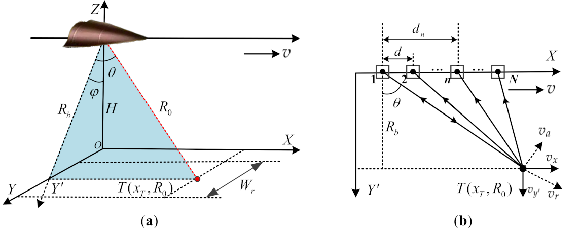
Figure 1. Geometric configuration of the HSV-MC-SAR systems. (a) HSV-SAR sketch with high-squint. (b) Data acquisition geometry at the slant range plane.
Remotesensing 13 02051 g001
Figure 2. The flowchart of our proposed method.
Remotesensing 13 02051 g002
Figure 3. Formulation of joint-pixel model.
Remotesensing 13 02051 g003
Figure 4. The beamformer of clutter suppression for different methods.
Remotesensing 13 02051 g004
Figure 5. The spatial variations of first- and second-order RCM with v = 2380 m/s and different squint angles. (a) Range walk versus flying time. (b) Range curvature versus flying time.
Remotesensing 13 02051 g005
Figure 6. The spatial variations of first- and second-order RCM at θ = 50 ° and different platform speed. (a) Range walk versus flying time. (b) Range curvature versus flying time.
Remotesensing 13 02051 g006
Figure 7. Channel errors versus squint angles.
Remotesensing 13 02051 g007
Figure 8. Cubic phase spatial variations for different squint angles. (a) Cubic RCM. (b) Cubic phase error in azimuth.
Remotesensing 13 02051 g008
Figure 9. Fourth-order phase spatial variations for different squint angles. (a) Fourth-order RCM. (b) Fourth-order phase error in azimuth.
Remotesensing 13 02051 g009
Figure 10. Distribution diagram of point scatterers.
Remotesensing 13 02051 g010
Figure 11. The results before (a) and after (b) coarse RWC.
Remotesensing 13 02051 g011
Figure 12. Results in the range compression and azimuth Doppler frequency domain. (a) After azimuth FT. (b) Local enlarge results in (a). (c) After azimuth second-order CFT. (d) After cubic CFT in azimuth.
Remotesensing 13 02051 g012
Figure 13. RS recovery results for different methods. (a) The absolute error of RS recovery versus RS. (b) The absolute error of RS recovery versus SCR.
Remotesensing 13 02051 g013
Figure 14. The beamformer of clutter suppression for different methods.
Remotesensing 13 02051 g014
Figure 15. Clutter suppression results. (a) Second-order CFT. (b) Cubic CFT.
Remotesensing 13 02051 g015
Figure 16. Accurate focusing procedures for the second GMT after clutter suppression. (a) The profiles in the 2-D time domain. The profiles after (b) decoupling, (c) accurate RWC, and (d) cubic RCMC.
Remotesensing 13 02051 g016
Figure 17. The imagery quality assessment for second GMT after accurate focusing. (a) 2-D responses. (b) Azimuth responses. (c) Range responses.
Remotesensing 13 02051 g017
Figure 18. Sketch of the experimental scene.
Remotesensing 13 02051 g018
Figure 19. Relocation results for different methods. (a) AMF. (b) SP. (c) WAMF. (d) Proposed.
Remotesensing 13 02051 g019
Table 1. Simulation parameters for the RCM analyses.
ParameterValueParameterValue
Carrier frequency10 GHzSignal bandwidth150 MHz
Wavelength0.03 mIncidence angle60°
Platform altitude30 kmRange resolution1 m
PRF554 HzAzimuth resolution1 m
Table 2. Simulation parameters.
ParameterValueParameterValue
Carrier frequency10 GHzSquint angle50°
Wave length0.03 mPlatform spend2380 (m/s)
Platform altitude30 kmChannel distance1.5 m
Center slant range60 kmDoppler bandwidth1530 Hz
Channel number5PRF554 Hz
Table 3. Performance assessment for different methods.
SCNR (dB)RS Absolute Error (m/s)HS Absolute Error (m/s)Calculation Time (s)
ISTAP19.212.582.6326.53
CFT-based26.275.13/1.96
CFT-improved28.621.911.405.46
Proposed30.710.150.163.28
Table 4. Parameters of real measured SAR data.
ParameterValueParameterValue
Pulse width10 usPRF1000 Hz
Sampling rate60 MHzChannel number3
Bandwidth40 MHzDoppler bandwidth417.4 Hz
Wavelength0.0339 mPlatform velocity115 m/s
Publisher’s Note: MDPI stays neutral with regard to jurisdictional claims in published maps and institutional affiliations.