Abstract
In complex urban environments, a single Global Navigation Satellite System (GNSS) is often not ideal for navigation due to a lack of sufficient visible satellites. Additionally, the heading angle error of a GNSS/micro-electro-mechanical system–grade inertial measurement unit (MIMU) tightly coupled integration based on the single antenna is large, and the attitude angle, velocity, and position calculated therein all have large errors. Considering the above problems, this paper designs a tightly coupled integration of GNSS/MIMU based on two GNSS antennas and proposes a singular value decomposition (SVD)-based robust adaptive cubature Kalman filter (SVD-RACKF) according to the model characteristics of the integration. In this integration, the high-accuracy heading angle of the carrier is obtained through two antennas, and the existing attitude angle information is used as the observation to constrain the filtering estimation. The proposed SVD-RACKF uses SVD to stabilize the numerical accuracy of the recursive filtering. Furthermore, the three-stage equivalent weight function and the adaptive adjustment factor are constructed to suppress the influence of the gross error and the abnormal state on the parameter estimation, respectively. A set of real measured data was employed for testing and analysis. The results show that dual antennas and dual systems can improve the positioning performance of the integrated system to a certain extent, and the proposed SVD-RACKF can accurately detect the gross errors of the observations and effectively suppress them. Compared with the cubature Kalman filter, the proposed filtering algorithm is more robust, with higher accuracy and reliability of parameter estimation.
1. Introduction
The integration of the Global Navigation Satellite System (GNSS) and the Strapdown Inertial Navigation System (SINS) is currently one of the main combined modes of application and research in the field of navigation and positioning [1]. The data fusion in tightly coupled navigation, especially fusing GNSS raw observations and micro-electro-mechanical system (MEMS)–grade inertial measurement unit (MIMU) data has become a hot topic in current research [2,3,4]. In addition, the multi-frequency and the multi-GNSS technologies are gradually maturing, and the supporting products on the market are becoming more economical and practical so that more redundant observation data can be used selectively [5,6].
GNSS technology has completely changed the way of acquiring spatiotemporal information and promoted the efficiency with which people achieve it. It has the advantages of being applicable in all weather with high accuracy, high efficiency, high reliability, low cost, etc. [7,8]. However, in semi- or fully shielded challenging environments, such as valleys, tree-lined roads, and tunnels, the positioning performance of GNSS will drop sharply due to insufficient reception of sufficient satellites. In contrast, MIMU has strong autonomy and high concealment and does not rely on any external information during the navigation phase [9,10]. The navigation process is to integrate using the output of MIMU. The initial value needs to be given before the navigation state gets into the normal state in SINS. However, the excessive integral calculation will lead to an accumulation of errors, which will seriously degrade the accuracy of navigation and positioning [9]. The combination of GNSS/MIMU realizes the complementary advantages of the two and can meet the needs for more efficient and reliable services. Commonly used GNSSs include the Global Positioning System (GPS) of the United States and the BeiDou Navigation Satellite System (BDS) of China. GNSS based on a single antenna can guarantee the position accuracy of the carrier for a long time. However, the heading angle error of the GNSS/MIMU tightly coupled integration based on a single antenna is relatively large, and the calculated attitude angle, velocity, and position are all subject to large errors [11]. Some studies have shown that a dual antenna can provide a more accurate heading angle and position information for the carrier, thereby ensuring the accuracy of navigation and positioning [12].
GNSS/MIMU integration modes are generally divided into three types: loose integration, tight integration, and deep integration [13,14]. The tight integration adopts the satellite ephemeris information received by the GNSS receiver and the position and velocity information output by the SINS to get the pseudo-range and pseudo-range rate from SINS and then combines it with that measured by the GNSS receiver [15]. Compared with loose integration, tight integration has a strong anti-interference ability and better dynamic performance; compared with deep integration, the structure and product of tight integration are simpler and more economical [13]. Therefore, tight integration has gradually become the main mode of theoretical research and product application [1,2,15].
The Kalman filter (KF) is a commonly used parameter estimator for data fusion in the field of navigation and positioning [16,17]. However, due to the nonlinearity of the GNSS/MIMU integrated navigation system model in practical applications, the traditional linear KF method cannot guarantee the accuracy of parameter estimation [18]. Nonlinear filtering methods such as the extended Kalman filter (EKF), the cubature Kalman filter (CKF), the fading cubature Kalman filter (FCKF), and the robust cubature Kalman filter (RCKF) have been applied to integrated navigation systems [18,19,20]. The EKF approximates the nonlinear system by a linear expansion of the current state, thereby introducing high-order truncation error, and it is cumbersome to calculate the Jacobian matrix [19]. The CKF is the nonlinear filtering based on Bayesian theory to solve the integration problem of the product of nonlinear function and Gaussian probability density [21]. Compared with Gaussian hypothesis nonlinear filtering methods such as EKF, the CKF has higher numerical accuracy and stability. However, the CKF cannot resist gross errors in observations and system abnormalities. Based on the principle of decaying memory, the FCKF adjusts the effect of observing and state prediction on the filtering estimation results by introducing fading factors, which can effectively suppress filtering divergence [20]. However, some FCKFs need to transfer the covariance matrix of the innovation of the current epoch to the next epoch when calculating the scalar fading factor [22]. This method is not suitable for tightly integrated navigation systems with constantly changing dimensions of innovation. Some other FCKFs have constraints on the dimensionality of design matrices, and they cannot be used in the observation models whose dimensionality of the design matrix is changing [20,23]. The RCKF adopts H∞ filtering to update the state vector covariance matrix or uses an equivalent weight function to modify the observation noise matrix in real time [18,24]. However, when encountering gross errors, their ability to suppress the influence of the errors is weak.
Due to the redundancy of the observation data in the tightly integrated navigation system, the observation with a larger gross error can be given a large variance or be abandoned in parameter estimation. Yang et al. [24] proposed a new equivalent weight function namely IGG (Institute of Geodesy and Geophysics) III. It divides the usage of observations into the following three categories: when the observations have no gross errors, the observations are kept and used, which is called “normal”; when the observations contain small gross errors, it can be used after its variance is slightly zoomed in, which is called “adjustment”; when there is a large error in the observations, its variance approaches infinity, which is called “abandonment”. Guo and Zhang [25] applied the IGGIII equivalent weight function for precise point positioning and achieved satisfactory results.
Taking into account the characteristics of the GNSS/MIMU tightly coupled integration model and the high numerical accuracy and stability of CKF, this paper proposes a novel robust adaptive cubature Kalman filter based on singular value decomposition called SVD-RACKF. The filter introduces a three-stage equivalent weight function to adjust the nominal variance of the observations with gross errors in real time and uses a two-stage adaptive factor to dynamically monitor state changes, which enhances the robustness of the filter and improves the accuracy of the filter estimation.
The rest of this paper is organized as follows. Section 2 introduces the dual-antenna GNSS/MIMU tightly coupled integrated model, including the system error dynamic model and the GNSS/MIMU observation model. Then, in Section 3, the construction of robust adaptive cubature Kalman filtering based on SVD is described in detail, in which the application of SVD, the three-stage equivalent weight function, and the selection of adaptive factor are discussed separately. Section 4 employs a set of real measurement data to test the improvement of the positioning performance of the integrated system in terms of dual-antenna, double GNSS, and the proposed filtering method. Finally, the discussion and conclusion are given in Section 5 and Section 6, respectively.
2. Dual-Antenna GNSS/MIMU Tightly Coupled Integration Model
2.1. System Error Dynamic Model
GNSS/MIMU tightly coupled integration uses north–east–up (N–E–U) geographic reference frame as the navigation coordinate system. Based on the SINS error equation, the state vector of the dynamic model of the integration system adds the relative errors of the GNSS receiver. It is composed of 17-dimensional error state parameters and expressed as [1]
where denotes the attitude angle error vector of the carrier; is the velocity error vector of the carrier; represents the position error vector of the carrier; indicates the zero-bias error of the three-axis accelerometer; indicates the drift error vector of the three-axis gyroscope; and , respectively, represent the system clock error and clock error drift of the receiver.
Due to errors caused by the SINS navigation algorithm and inertial devices, there is a slight deviation between the actual application coordinate system and the ideal navigation coordinate system, called attitude angle error, whose vector form is expressed as follows [26,27]:
where b stands for carrier frame, e represents the Earth centered Earth fixed (ECEF) coordinate system; i denotes the geocentric inertial system and n represents the local navigation coordinate system; and are the angular rates of e frame relative to i frame and n frame relative to e frame, respectively; and represent angular rate errors; represents the conversion matrix from b frame to n frame; indicates gyro drift error. The velocity error is caused by the difference between the calculated velocity and the real velocity. Its vector expression is [27,28]
where indicates the specific force measured by the accelerometer; represents the accelerometer deviation error vector; indicates the local gravity error. Due to error transitivity, the position vector also has a certain deviation, which is modeled as [28]
where represents the rotation matrix between the actual frame and the ideal navigation frame; and represent the position errors of the carrier in the north and east directions, respectively; and indicate the radius of curvature of the meridian circle and the radius of curvature of the prime vertical, respectively; h is the height; and is the local latitude. To refine the error of the inertial sensor, the noises of the gyroscope and accelerometer are considered and regarded as random walk process vector, respectively. Their error equations are given as follows [1]:
where and are the white Gaussian noise vectors. In GNSS/MIMU tightly coupled integration, the clock error and clock error drift of the GNSS receiver are [27]
where T is the relevant time, and are the white Gaussian noise of the receiver clock error and the receiver clock error drift, respectively.
By combining Equations (2)–(9), the discretized error dynamic model of the integrated navigation system can be expressed as the following matrix-vector form:
where represents the error state vector; denotes the state transition matrix; represents the system noise drive matrix; and is the system noise vector.
2.2. The Observation Model of GNSS/MIMU Integration
The positions of the carrier and the satellite can be obtained through SINS mechanization and satellite ephemeris, and the SINS-derived pseudo-range between the carrier and the satellite can be calculated by using the spatial solid geometry theory. Carrying out Taylor expansion on the SINS pseudo-range at the carrier position, only the first-order term is retained, and the following equation can be obtained [29,30]:
where is the SINS pseudo-range; is the true distance of the carrier relative to the satellite; , , and are the direction cosines from the carrier to the satellite in the x, y, and z directions, respectively; , , and are the position error components in the ECEF system. The GNSS receiver can also measure the pseudo-range of the carrier relative to the satellite, that is, the GNSS pseudo-range. With tropospheric error, ionospheric error, and satellite clock error eliminated, the GNSS pseudo-range can be expressed as [29]
where is the GNSS pseudo-range; represents GNSS pseudo-range noise. By subtracting Equations (12) from (11), the pseudo-range difference observation equation of GNSS/MIMU tightly coupled integration can be obtained as follows:
Through SINS, the pseudo-range rate between the carrier and the satellite can be calculated as [29,30]
where indicates the carrier velocity calculated by SINS; represents the satellite velocity calculated by the GNSS satellite ephemeris. Similarly, the pseudo-range rate between the carrier and the satellite obtained by the GNSS receiver is [30]
where indicates the carrier velocity calculated by the GNSS receiver; represents the GNSS pseudo-range rate noise. By subtracting Equations (15) from (14), the pseudo-range rate difference observation equation of GNSS/MIMU tightly coupled integration can be written as follows:
Combining Equations (12) and (15) with the attitude angle information provided by the dual antennas, the discretized measurement equation can be obtained as
where is the design matrix; is the observation noise vector.
3. Robust Adaptive Cubature Kalman Filter Based on SVD
3.1. Cubature Kalman Filter Using SVD
The CKF adopts the principle of numerical integration based on the third-order spherical–radial cubature rule to calculate the mean and covariance of random variables after nonlinear transformation [31], which is easy to implement and has high filtering accuracy. To ensure the non-negative qualitative and numerical accuracy of the variance matrix in the whole filtering process, this paper uses SVD instead of Cholesky decomposition to improve the robustness of the filtering numerical calculation and solve the potential weak ill-conditioned issue of the covariance matrix. Before the filtering starts, first, the cubature sampling points and the corresponding weights are calculated as follows [21,31]:
where n represents the dimension of the state vector, m indicates the number of cubature sampling points, and they satisfy m = 2n, and ; represents the ith point of the point set generated by the full arrangement of the elements of the n-dimensional unit vector and the change of the element sign.
Second, we accomplish the filtering time update. The calculation equations of the cubature point at this stage and the cubature point propagated through the nonlinear state equation are as follows [18]:
where is the estimated state vector; and are obtained by performing SVD on . The predicted state vector and its covariance matrix are [31,32]
where represents the system noise matrix.
Then, the measurement update is performed. The calculation equations of the cubature point at this stage and the cubature point propagated through the nonlinear state equation are as follows [18]:
The predicted state vector measurement value, the innovation covariance matrix, and the covariance matrix of the two-step prediction state vector are described as [32]
where represents the measurement noise matrix. The filter gain matrix , the estimated state vector , and its covariance matrix take the following general form [3,32]:
3.2. The Robust Equivalent Weight Function for the Observation Noise Covariance Matrix
When there is a gross error in the observations at one epoch, the actual noise statistics of the filter will be different from the nominal measurement noise matrix. The most direct method is to accurately update the variance of the observation to avoid the effect of gross error on filtering accuracy. At present, the commonly used robustness schemes are Huber weight function, IGG (Institute of Geodesy and Geophysics) III weight function, H∞ filtering, etc. [18,24,25]. To divide the observations with gross errors in more detail and to ensure the accuracy of the equivalent weight function to adjust the errors in the observations, this paper adopts a three-stage robust equivalent weight function similar to the IGGIII scheme to calibrate the nominal variance matrix element by element [24]:
where indicates amplification factor of the variance, represents the standardized prediction residual of ith observation, and is the weight function adjustment threshold. The adjusted variance and the nominal variance satisfy .
3.3. The Adaptive Adjustment Factor for the Predicted Error Covariance Matrix
When the carrier is moving complexly, it is difficult to accurately describe the actual maneuvering state using the statistical information of the traditional dynamic model. The system model needs a mechanism to monitor this change to adjust the predicted error covariance matrix in real time. In GNSS/MIMU tightly coupled integration, the number of visible satellites is not always greater than the number of parameters to be estimated by filtering, so the adaptive factor based on the prediction state or the variance component ratio is not suitable for this situation [33]. To enhance the real-time performance and reliability of the parameter estimation of the integrated system, this paper adopts a two-stage adaptive adjustment factor to weaken the influence of the state disturbance on parameter estimation, and to avoid the problem of excessive expansion of the variance. The structure of the adaptive factor is similar to the Huber equivalent weight function as shown below [33,34]:
where indicates the adaptation factor; represents the state deviation statistics, is the predicted residual vector, is the covariance matrix of ; and c indicates the adaptive adjustment threshold. Correspondingly, the improved filter gain matrix is described as
Figure 1 shows the dual-antenna GNSS/MIMU tightly coupled integration and filtering mechanism constructed in this paper. This mechanism adopts the pseudo-range difference, the pseudo-range rate difference, and the attitude angle information provided by the dual antennas as observations to estimate unknown parameters, and some of the necessary errors are corrected. The observations of MIMU are uninterrupted, which can meet the instantaneity of navigation and positioning. When there are enough available satellites, the pseudo-range and pseudo-range rate calculated by GNSS can help MIMU weaken the positioning error. However, when the number of available GNSS satellites is insufficient, the observations calculated by MIMU can be used solely as the filtering input. The longer the pure MIMU system works, the lower the state estimation accuracy will be [35].
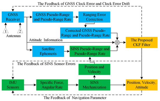
Figure 1.
The dual-antenna GNSS/MIMU tightly coupled integration mechanism using the proposed CKF filter. GNSS: Global Navigation Satellite System; IMU: inertial measurement unit; MIMU: micro-electro-mechanical system–grade IMU; SINS: Strapdown Inertial Navigation System; and CKF: cubature Kalman filter.
4. Experiments
To verify the effectiveness and practicability of the proposed SVD-RACKF method for GNSS/MIMU tightly coupled integration, a set of data collected in a sports field in Beijing was employed for testing. The experimental equipment used was a NovAtel SPAN portable multifunctional receiver and the model was PwrPak7D-E1. The receiver has a built-in OEM7 GNSS board and a commercial MEMS-grade IMU. The model of the IMU was Epson G320N, and its technical parameters are given in Table 1. The equipment was mounted on a trolley, which drove around the runway for about 20 min. The sampling rates of GNSS and SINS observation data were 1 and 125 Hz, respectively. To simulate the complex movement in the urban environment, the trolley drove on an “S”-shaped route, and successively, drove in a semi-shielded environment caused by white buildings. The specific driving route is shown in Figure 2. In addition, while the trolley was traveling, another receiver acted as a base station to observe the satellites in real time in an open area. The RTK/INS mode of the commercial software Inertial Explorer was used to process the collected observation data, and the result of the software output was used as the reference value of this test.

Table 1.
The performance specifications of Epson G320N IMU.
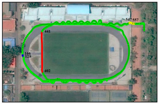
Figure 2.
Trolley trajectory collected in a sports field in Beijing. The background image is obtained from LocaSpace Viewer. The blue track points indicate that the trolley is at rest (during epoch 129–166); the red track points indicate that the trolley is moving in a straight line in an approximate north direction (during epoch 402–441); the yellow track points indicate that the trolley is passing on uneven roads (during epoch 547–557).
Figure 3 describes the driving velocity of the trolley. The average velocity of the trolley in the north, east, and up directions is 0.751, 1.089, and 0.026 m/s, respectively. It is worth noting that the trolley was at a standstill during epoch 129 to 166. In addition, during epochs 402 to 441, the trolley only has a greater speed in the north direction. This can help us roughly determine the north direction of the navigation coordinate system in Figure 2. In order to analyze the changes in the number of visible satellites during the movement of the receiver, we separately counted the number of visible satellites and calculated the position dilution of precision (PDOP) in three modes: single GPS, single BDS, and GPS + BDS as shown in Figure 4. The average number of visible satellites in single GPS, single BDS, and GPS + BDS modes was 7.6, 8.5, and 16.0, respectively. The PDOP of the GPS + BDS combination mode was significantly reduced and more stable than the other two modes. Approximately during epoch 547 to 557, the number of visible satellites of GPS and BDS dropped sharply. The number of GPS satellites was at least four, and the number of BDS satellites was at least three. This is a challenge for the integrated system to complete accurate positioning.
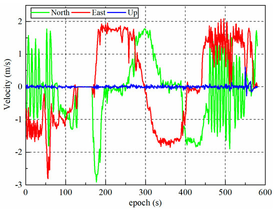
Figure 3.
The driving velocity of the trolley in different directions.
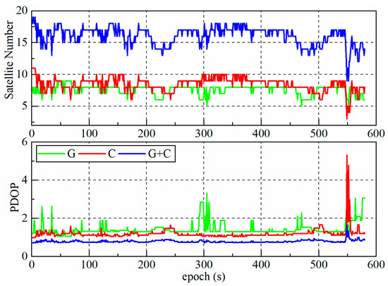
Figure 4.
The number of visible satellites and position dilution of precision (PDOP) for single GPS (G), single BDS (C), and their combination (G + C).
4.1. The Effect of Dual-Antenna Observation Data on Attitude Correction and Positioning Accuracy
The test data in this work were collected by a dual-antenna multi-function receiver, in which dual antennas are optional. To analyze the influence of dual-antenna orientation on carrier attitude correction and positioning accuracy, this section performs tests on the single-antenna mode and dual-antenna mode in the tightly coupled integration of GNSS/MIMU. In order to prevent the proposed SVD-RACKF algorithm from exerting different performance in different modes and thus affecting the comparison result, this test uses the EKF to estimate the parameters, and the satellite system adopted the more commonly used GPS + BDS combination.
Figure 5 shows the position error of the GNSS/MIMU tightly coupled integration in single-antenna mode and dual-antenna mode. It can be seen that during epoch 450 to 520, there are obvious differences in the position errors of the N–E–U directions. Compared with the single-antenna model, the position error of the dual-antenna mode in the N–E direction is smaller, while that in the U direction is larger. Table 2 shows the root mean square (RMS) of the position, velocity, and attitude error of the GNSS/MIMU tightly coupled integration in the single-antenna mode and the dual-antenna mode. Through comparison, it can be concluded that the three-dimensional position error in the dual-antenna mode is smaller and the result is more accurate. This is because the trolley is close to the white building shown in Figure 2 during this period and makes an “S”-shaped trajectory. This semi-occluded environment and complex movement reduced the number of visible satellites and fewer satellites could be observed using a single antenna. The ability of autonomous orientation of the single-antenna model is weak. Moreover, the dual-antenna mode has certain advantages in harsh environments. The short baseline vector formed by the antennas can determine the yaw and pitch angles of the trolley to correct the attitude angle estimated by the filter.
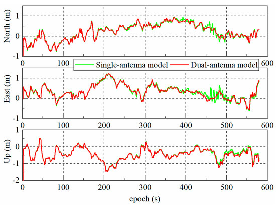
Figure 5.
Position errors of dual-system (GPS + BDS) GNSS/MIMU tightly coupled integration using the EKF in single-antenna mode and dual-antenna mode.
Table 2.
Root mean square (RMS) of position, velocity, and attitude error of dual-system (GPS + BDS) GNSS/MIMU tightly coupled integration using the EKF in single-antenna mode and dual-antenna mode, respectively.
Figure 6 shows the velocity error of the GNSS/MIMU tightly coupled integration in single-antenna mode and the dual-antenna mode. Between epoch 450 and 520, the velocity errors of the dual-antenna mode in the N–E–U directions are smaller than those of the single-antenna mode. Figure 7 shows the attitude angle error of GNSS/MIMU tightly coupled integration single-antenna mode and dual-antenna mode, respectively. As can be seen from the Figure 7, the superiority of the dual-antenna mode makes the errors of roll and pitch angles significantly reduced. Since the yaw angle obtained after the dual-antenna orientation is added to the observation vector, the yaw angle estimated by the filter is constrained in real time, avoiding the accumulation of heading angle errors. According to Table 2, the dual-antenna mode is 51.3%, 12.5%, and 97.2% higher than the single-antenna mode in the roll, pitch, and yaw directions, respectively.
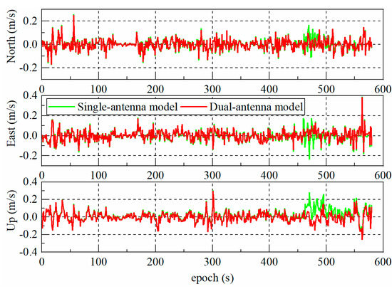
Figure 6.
Velocity error of dual-system (GPS + BDS) GNSS/MIMU tightly coupled integration using the EKF in single-antenna mode and dual-antenna mode.
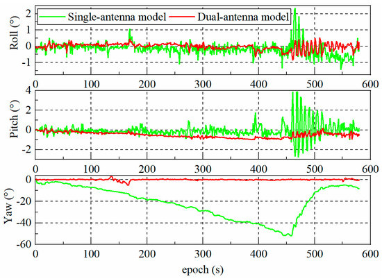
Figure 7.
Attitude angle error of dual-system (GPS + BDS) GNSS/MIMU tightly coupled integration using the EKF in single-antenna mode and dual-antenna mode.
4.2. Analysis of the Impact of Different GNSS and Their Combinations on Positioning Accuracy
In the challenging environment of a city, the number of available satellites for a single GNSS may be too small, so that navigation and positioning cannot be carried out normally or there is a large error in the positioning results. Different GNSS combinations can significantly increase the number of available satellites, and the redundant observation information can be used or discarded using quality-inspection methods, to improve the positioning accuracy as much as possible. In order to study the impact of data fusion of different GNSSs on the performance of GNSS/MIMU tightly coupled integrated positioning, velocity measurement, and attitude measurement, and to test the processing performance of the SVD-RACKF method proposed in this paper on the fusion data, the GNSS/MIMU tightly coupled integration under single GPS, single BDS, and their combination (GPS + BDS) were tested, respectively. The SVD-RACKF method was used as the parameter estimator, and the dual-antenna mode was adopted to determine the heading angle of the carrier.
Figure 8 shows the position errors in different GNSS situations. It can be seen that the position error based on GPS + BDS is significantly lower than that based on GPS or BDS in all directions. Table 3 shows the RMS of position, velocity, and attitude error of GNSS/MIMU tightly coupled integration in three GNSS schemes. Compared with the position error of the GPS-based test, the position error of the GPS + BDS–based test is improved by 5.8%, 44.7%, and 61.5% in the three directions of N–E–U, respectively. Figure 9 shows the velocity error of GNSS/SINS tightly coupled integration in three GNSS schemes. The velocity error based on GPS + BDS is significantly lower than that based on GPS or BDS in all directions. Compared with the velocity error of the GPS-based test, the velocity error of the GPS + BDS–based test is improved by 24.1%, 43.3%, and 13.4% in the three directions of N–E–U, respectively. Figure 10 shows the attitude angle errors of GNSS/MIMU tightly coupled integration in three GNSS schemes. Combined with Table 3, it can be obtained that, compared with the attitude angle error of the GPS-based test, the attitude angle error of the GPS + BDS–based test is improved by 27.0%, 12.1%, and 0.4% in the three directions of N–E–U, respectively. The GPS + BDS combination improves the heading angle slightly. This is because all the tests in this section adopted the dual-antenna mode. Whether it is based on the GPS or the GPS + BDS combination, the heading angle of these tests was more accurately constrained. All in all, the combination of different GNSSs can improve the positioning, velocity, and attitude accuracy of the integrated system to a certain extent. The test results show that the SVD-RACKF proposed in this paper is feasible and has strong practicability.
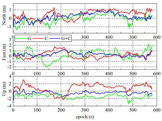
Figure 8.
Position error of dual-antenna GNSS/MIMU tightly coupled integration using the SVD-RACKF in the case of single GPS (G), single BDS (C), and their combination (G + C).
Table 3.
RMS of position, velocity, and attitude error of dual-antenna GNSS/MIMU tightly coupled integration using the SVD-RACKF in the case of single GPS (G), single BDS (C), and their combination (G + C).
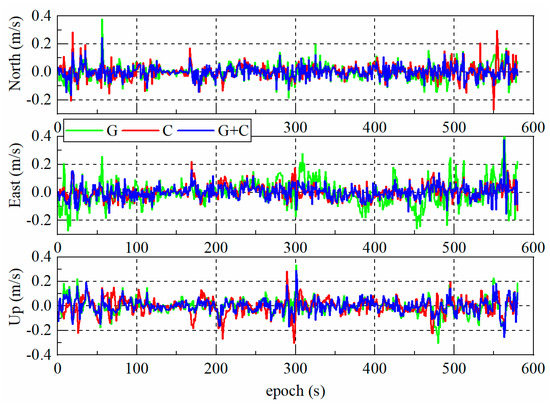
Figure 9.
Velocity error of dual-antenna GNSS/MIMU tightly coupled integration using the SVD-RACKF in the case of single GPS (G), single BDS (C), and their combination (G + C).
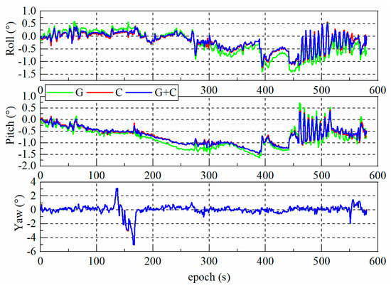
Figure 10.
Attitude angle error of dual-antenna GNSS/MIMU tightly coupled integration using the SVD-RACKF in the case of single GPS (G), single BDS (C), and their combination (G + C).
4.3. Robustness Evaluation of the Proposed Filtering Algorithm
In practical applications, due to the instability of the observation signal in the emission, transmission, and reception process, there will be some gross errors in some observations. In order to better verify the robustness of SVD-RACKF, this paper simulated five gross errors and then added them into pseudo-range observations. For the pseudo-range rate observations without simulated gross errors, we treated them as having no gross errors. The test was carried out in a dual-antenna GNSS/MIMU tightly coupled integration, and the satellite system used the GPS + BDS combination mode. Figure 11 shows the time series of the pseudo-range and pseudo-range rate test statistics based on the proposed robustness method. According to the two adjustment thresholds used in this paper, the test statistics were color coded into different categories, and the statistics with colors of red and black belong to outliers. The statistics shown in red in Figure 11 are located at epoch 120, 150, 230, 496, and 517 in order. There were no outliers in the pseudo-range rate test statistics. This shows that the robust method accurately detects the position of the gross error in the pseudo-range observations and does not detect falsely.
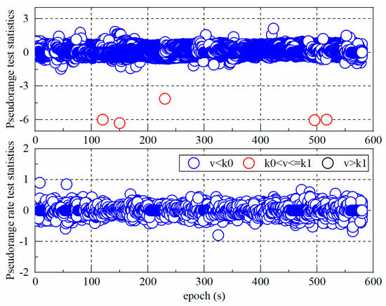
Figure 11.
Standardized prediction residual sequence of dual-system (GPS + BDS) dual-antenna GNSS/MIMU tightly coupled integration using the SVD-RACKF scheme.
To demonstrate the superiority of SVD-RACKF, the cubature Kalman filter without simulated gross error (CKFN) was tested against the cubature Kalman filter with simulated gross error (CKFY) and the SVD-RACKF with simulated gross error. Figure 12 shows the position error of different schemes. It can be seen that SVD-RACKF can effectively suppress the influence of gross errors on state estimation. Table 4 shows the RMS and standard deviation (STD) of the position error using the dual-system (GPS + BDS) dual-antenna GNSS/MIMU tightly coupled integration using different filtering schemes. Compared with CKFY, the RMS of SVD-RACKF is closer to that of CKFN, which shows that SVD-RACKF can enhance the robustness of CKF and improve the positioning accuracy of the integrated system. It can be seen from Table 4 that the gross error elimination rates of the proposed method reach 100%, 100%, and 91.2% in three directions of N–E–U, respectively.
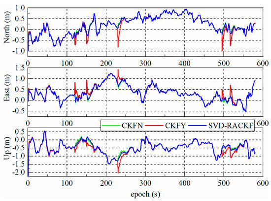
Figure 12.
Position error of dual-system (GPS + BDS) dual-antenna GNSS/MIMU tightly coupled integration using different filtering schemes.
Table 4.
RMS and STD of the position error of dual-system (GPS + BDS) dual-antenna GNSS/MIMU tightly coupled integration using different filtering schemes.
5. Discussion
In single-antenna GNSS/MIMU tightly coupled integration, the heading angle easily diverges and becomes invalid when the carrier is stationary or moving linearly, and the error is relatively large [11]. Section 4.1 analyzes the influence of dual GNSS antenna observation data on attitude correction and positioning accuracy. Combining Figure 3 and Figure 7, it can be seen that when the carrier repeats the “S”-shaped trajectory movement, that is, when the heading angle changes greatly in a short time, the single-antenna heading angle error will gradually converge; when the actual heading angle of the carrier shows little or no change in a short period, the heading angle error of a single antenna will gradually accumulate. This phenomenon is related to the technical performance of the inertial unit. However, the dual-antenna GNSS/MIMU tightly coupled integration can provide higher-accuracy heading angles when the carrier is stationary and in linear motion and can effectively improve the estimation accuracy of the carrier’s attitude [12]. Moreover, we found dual GNSSs have more visible satellites and higher positioning accuracy than a single GNSS. Section 4.2 analyzes the impact of different GNSSs and their combinations on positioning accuracy. Due to factors such as the number of visible satellites and signal quality, the position, velocity, and attitude angle accuracy of a single GPS or a single BDS are lower than that of GPS + BDS. The results show that the GPS + BDS combination can provide a better satellite layout for the navigation system, and enough visible satellites can reduce the PDOP and enhance the stability and reliability of the navigation system. On the other hand, the state of the carrier when the GNSS/MIMU integrated system is working is usually dynamic. Due to the irregularity of movement and the influence of the surrounding environment on the carrier, it is difficult for CKF to accurately estimate the system noise and measurement noise at the same time [21]. The accuracy and stability of parameter estimation need to be improved. The wrong estimation will pass the error to the estimation of the next few epochs through the recursive process, and even lead to the filtering divergence. Section 4.3 tests the robustness of the proposed SVD-RACKF method. The test results show that the standardized innovation and state statistics of SVD-RACKF can accurately describe the characteristics of the observations of the current epoch and the system state, respectively. This method can identify all simulated gross errors, ensuring filter stability and positioning accuracy.
It is worth noting that the positioning performance of different GNSS-aided MIMU tightly coupled integrations based on dual antennas is different, which mainly depends on the number of available GNSS satellites and the quality of the observation data. The tightly coupled integration of dual-antenna GNSS/MIMU can enhance the positioning accuracy of the system, provided that the quality of the observation data of the double GNSS is good, otherwise, the performance of the double GNSS scheme may not be satisfactory. Due to the limitations of the current experimental equipment, this paper did not test the data fusion capability of SVD-RACKF in the tightly coupled integration of multi-GNSS/MIMU. We will further carry out this work when conditions permit.
6. Conclusions
At present, the low-cost GNSS/MIMU tightly coupled integration has gradually become the focus of research, production, and application. The tightly coupled mode has become the main mode used in data fusion due to its advantages such as strong anti-interference ability and good dynamic performance. In addition, dual GNSS antennas can assist in correcting attitude information such as carrier heading angles, which can be used as an option to enhance the navigation performance of low-cost MIMUs. Taking into account the above factors, we designed a GNSS/MIMU tightly coupled integration mechanism based on dual antennas. According to the characteristics of the model, we propose a parameter estimator, namely SVD-RACKF, which is more robust and accurate than CKF.
Pseudo-range and pseudo-range rate are regarded as parts of the observations in this tightly coupled integration. The dual-antenna data are processed to provide observation information such as carrier heading angle for filtering. SVD-RACKF uses SVD to enhance the robustness of numerical decomposition, employs a three-stage equivalent weight function constructed by standardized innovation to adjust the observation noise in real-time, and adopts a state statistic to construct the adaptive factor to suppress the impact of abnormal state for filtering estimation. A set of measured data is employed to test the improvement of the positioning performance of the integrated system using dual antennas, different GNSSs, and the proposed filtering method. The experimental results show that dual antennas can assist the integrated system to improve the accuracy of positioning, velocity measurement, and attitude measurement. Among them, the estimation accuracy of attitude angle has the highest improvement rate, which is improved by 51.3%, 12.5%, and 97.2% in the three directions of roll, pitch, and yaw, respectively. Different GNSSs have different effects on the tightly coupled integration of GNSS/MIMU. Under the condition of stable data quality, dual GNSSs can significantly improve the positioning accuracy of the integrated system. The improvement rates in the N–E–U directions are 5.8%, 44.7%, and 61.5%, respectively. The SVD-RACKF method can significantly improve the robustness of CKF, and the five simulated errors are accurately detected and processed. Compared with the positioning results of CKF, the gross error elimination rates of the proposed method reach 100%, 100%, and 91.2% in three directions of N–E–U, respectively.
Author Contributions
Conceptualization, C.P.; funding acquisition, J.G.; project administration, J.G.; validation, C.P.; visualization, C.P.; writing—original draft, C.P.; writing—review and editing, N.Q., Z.L. (Zengke Li), Z.L. (Zhenbin Liu), and K.S. All authors have read and agreed to the published version of the manuscript.
Funding
This work is supported by the National Natural Science Foundation of China (grant no. 41874006, 41974026), the Assistance Program for Future Outstanding Talents of China University of Mining and Technology (grant no. 2020WLJCRCZL052), and the Postgraduate Research and Practice Innovation Program of Jiangsu Province (grant no. KYCX20_2058).
Acknowledgments
Thanks to Xiao Liu from Beijing Satellite Navigation Center for his assistance in data collection and processing.
Conflicts of Interest
The authors declare no conflict of interest.
References
- Li, Z.; Gao, J.; Wang, J.; Yao, Y. PPP/INS tightly coupled navigation using adaptive federated filter. GPS Solut. 2017, 21, 137–148. [Google Scholar] [CrossRef]
- Yang, Y. Tightly Coupled MEMS INS/GPS Integration with INS Aided Receiver Tracking Loops. Ph.D. Thesis, University of Calgary, Calgary, AB, Canada, 2008. [Google Scholar]
- Shen, C.; Zhang, Y.; Tang, J.; Cao, H.; Liu, J. Dual-optimization for a MEMS-INS/GPS system during GPS outages based on the cubature Kalman filter and neural networks. Mech. Syst. Signal Process. 2019, 133, 106222. [Google Scholar] [CrossRef]
- Abdolkarimi, E.S.; Mosavi, M.-R. A low-cost integrated MEMS-based INS/GPS vehicle navigation system with challenging conditions based on an optimized IT2FNN in occluded environments. GPS Solut. 2020, 24, 108. [Google Scholar] [CrossRef]
- Chen, C.; Chang, G. PPPLib: An open-source software for precise point positioning using GPS, BeiDou, Galileo, GLONASS, and QZSS with multi-frequency observations. GPS Solut. 2020, 25, 18. [Google Scholar] [CrossRef]
- Pan, C.; Li, Z.; Gao, J.; Li, F. A variational Bayesian-based robust adaptive filtering for precise point positioning using undifferenced and uncombined observations. Adv. Sp. Res. 2021, 67, 1859–1869. [Google Scholar] [CrossRef]
- Edokossi, K.; Calabia, A.; Jin, S.; Molina, I. GNSS-Reflectometry and remote sensing of soil moisture: A review of measurement techniques, methods, and applications. Remote Sens. 2020, 12, 614. [Google Scholar] [CrossRef]
- Innerkofler, J.; Kirchengast, G.; Schwärz, M.; Pock, C.; Jäggi, A.; Andres, Y.; Marquardt, C. Precise orbit determination for Climate applications of GNSS radio occultation including uncertainty estimation. Remote Sens. 2020, 12, 1180. [Google Scholar] [CrossRef]
- Zhang, T.; Xu, X. A new method of seamless land navigation for GPS/INS integrated system. Measurement 2012, 45, 691–701. [Google Scholar] [CrossRef]
- Ma, L.; You, Z.; Liu, T.; Shi, S. Coupled integration of CSAC, MIMU, and GNSS for improved PNT performance. Sensors 2016, 16, 682. [Google Scholar] [CrossRef]
- Li, Z.; Gao, J.; Wang, J. Inertial aided cycle slip detection and repair for PPP/INS tightly coupled navigation. J. Navig. 2016, 69, 1357–1378. [Google Scholar] [CrossRef]
- Wu, Z.; Yao, M.; Ma, H.; Jia, W.; Tian, F. Low-cost antenna attitude estimation by fusing inertial sensing and two-antenna GPS for Vehicle-Mounted Satcom-on-the-Move. IEEE Trans. Veh. Technol. 2013, 62, 1084–1096. [Google Scholar] [CrossRef]
- Falco, G.; Pini, M.; Marucco, G. Loose and tight GNSS/INS integrations: Comparison of performance assessed in real urban scenarios. Sensors 2017, 17, 255. [Google Scholar] [CrossRef]
- Niu, X.; Ban, Y.; Zhang, Q.; Zhang, T.; Zhang, H.; Liu, J. Quantitative analysis to the impacts of IMU quality in GPS/INS deep integration. Micromachines 2015, 6, 1082–1099. [Google Scholar] [CrossRef]
- Reuper, B.; Becker, M.; Leinen, S. Benefits of multi-constellation/multi-frequency GNSS in a tightly coupled GNSS/IMU/odometry integration algorithm. Sensors 2018, 18, 3052. [Google Scholar] [CrossRef]
- Georgy, J.; Noureldin, A.; Korenberg, M.J.; Bayoumi, M.M. Modeling the stochastic drift of a MEMS-based gyroscope in Gyro/Odometer/GPS integrated navigation. IEEE Trans. Intell. Transp. Syst. 2010, 11, 856–872. [Google Scholar] [CrossRef]
- Ruiz, A.R.J.; Granja, F.S.; Honorato, J.C.P.; Rosas, J.I.G. Accurate pedestrian indoor navigation by tightly coupling foot-mounted IMU and RFID measurements. IEEE Trans. Instrum. Meas. 2012, 61, 178–189. [Google Scholar] [CrossRef]
- Zhang, Q.; Meng, X.; Zhang, S.; Wang, Y. Singular value decomposition-based robust cubature Kalman filtering for an integrated GPS/SINS navigation system. J. Navig. 2015, 68, 549–562. [Google Scholar] [CrossRef]
- Zhan, R.; Wan, J. Neural network-aided adaptive unscented Kalman filter for nonlinear state estimation. IEEE Signal Process. Lett. 2006, 13, 445–448. [Google Scholar] [CrossRef]
- Geng, Y.; Wang, J. Adaptive estimation of multiple fading factors in Kalman filter for navigation applications. GPS Solut. 2008, 12, 273–279. [Google Scholar] [CrossRef]
- Arasaratnam, I.; Haykin, S. Cubature Kalman smoothers. Automatica 2011, 47, 2245–2250. [Google Scholar] [CrossRef]
- Pan, C.; Gao, J.; Li, Z.; Qian, N.; Li, F. Multiple fading factors-based strong tracking variational bayesian adaptive Kalman filter. Measurement 2021, 176, 109139. [Google Scholar] [CrossRef]
- Gao, W.; Miao, L.; Ni, M. Multiple fading factors Kalman filter for SINS static alignment application. Chin. J. Aeronaut. 2011, 24, 476–483. [Google Scholar] [CrossRef]
- Yang, Y.; He, H.; Xu, G. Adaptively robust filtering for kinematic geodetic positioning. J. Geod. 2001, 75, 109–116. [Google Scholar] [CrossRef]
- Guo, F.; Zhang, X. Adaptive robust Kalman filtering for precise point positioning. Meas. Sci. Technol. 2014, 25, 105011. [Google Scholar] [CrossRef]
- Shin, E.-H. Estimation Techniques for Low-Cost Inertial Navigation. Ph.D. Thesis, University of Calgary, Calgary, AB, Canada, 2005. [Google Scholar]
- Duan, S.-l.; Sun, W.; Wu, Z.-l. Application of robust adaptive EKF in INS/GNSS tight combination. J. Univ. Electron. Sci. Technol. China 2019, 48, 58–62. [Google Scholar] [CrossRef]
- Ma, C.; Zhang, Q.; Meng, X.; Zheng, N.; Pan, S. A Novel ambiguity parameter estimation and elimination strategy for GNSS/INS tightly coupled integration. Remote Sens. 2020, 12, 3514. [Google Scholar] [CrossRef]
- Zang, Z. Research of SINS/GPS Tightly Integrated Navigation System Based on Pseudo-Range and Pseudo-Range Rate. Master Thesis, Beijing Institute of Technology, Beijing, China, 2015. (In Chinese). [Google Scholar]
- Xie, L.; YE, S.; HU, N. Tightly GPS/INS integrated navigation system based on single frequency pseudo-range and its rate. Sci. Technol. Eng. 2017, 17, 341–346. (In Chinese) [Google Scholar] [CrossRef]
- Arasaratnam, I.; Haykin, S. Cubature Kalman filters. IEEE Trans. Automat. Contr. 2009, 54, 1254–1269. [Google Scholar] [CrossRef]
- Cui, B.; Chen, X.; Tang, X. Improved cubature Kalman filter for GNSS/INS based on transformation of posterior sigma-points error. IEEE Trans. Signal Process. 2017, 65, 2975–2987. [Google Scholar] [CrossRef]
- Zhang, Q.; Zhao, L.; Zhao, L.; Zhou, J. An improved robust adaptive kalman filter for GNSS precise point positioning. IEEE Sens. J. 2018, 18, 4176–4186. [Google Scholar] [CrossRef]
- Huber, P.J. Robust Statistics; John Wiley & Sons: New York, NY, USA, 1981. [Google Scholar]
- Fang, W.; Jiang, J.; Lu, S.; Gong, Y.; Tao, Y.; Tang, Y.; Yan, P.; Luo, H.; Liu, J. A LSTM algorithm estimating pseudo measurements for Aiding INS during GNSS Signal Outages. Remote Sens. 2020, 12, 256. [Google Scholar] [CrossRef]


Publisher’s Note: MDPI stays neutral with regard to jurisdictional claims in published maps and institutional affiliations. |
© 2021 by the authors. Licensee MDPI, Basel, Switzerland. This article is an open access article distributed under the terms and conditions of the Creative Commons Attribution (CC BY) license (https://creativecommons.org/licenses/by/4.0/).