Abstract
Probability of collision between non-cooperative space object (NCSO) and the reference spacecraft (RS) has been increased drastically over the past few decades. The traditional method is difficult to identify the maneuvering of non-cooperative space object. In the present paper, not only positions and velocities, but also accelerations of non-cooperative space object are estimated as parameters by the extended Kalman filtering based on setting up the state linear equation and measurement model of the non-cooperative space object. The algorithm for predicting collision probability is derived from position error ellipsoid, and the algorithm for determining maneuvering probability is derived from maneuvering acceleration and its error ellipsoid, which can be employed to identify whether the upcoming space object is being maneuvered. An epoch Earth-centered inertial (EECI) coordinate system is suggested to replace Earth-centered inertial (ECI) to simplify coordinate transformation. Finally, a set of simulations were conducted to validate the proposed algorithms with the simulated measurement data of the reference spacecraft space-borne millimeter-wave (MMW) radar.
1. Introduction
The non-cooperative space object (NCSO) refers to the space object which cannot provide effective information, such as the disabled or discarded satellites, space debris, or the rival spacecraft in space which may surveil or harm the reference spacecraft (RS) that is performing a mission. With the development of astronautics technology over the past decades, the number of space activities surges rapidly. On one end, collision probability between RS and NCSOs has therefore increased. On the other end, some NCSOs might approach RS intentionally for some purposes. These can be serious threats to RS mission. It is crucial to monitor the status of the NCSOs nearby in order to avoid collision [1]. Technically, estimating orbit parameters, identifying orbit maneuvering, and predicting collision probability of NCSOs are the three main tasks of NCSOs monitoring.
A variety of research on orbital mechanics modeling can be found in the literature. A non-Gaussian error propagation model was set up by Junkins et al. [2]; the model was evaluated in different cases and proved to be successful. A modeling error index was proposed by Alfriend et al. [3] for grading the accuracy of different satellite relative motion models. The modeling error index provides a foundation for differentiating various relative orbital variables and models. By using the measurement data from on-board sensors on the spacecraft, there are three main methods for space object orbit estimation: geometric method [4], dynamic method [5], and geometric dynamic method [6,7]. A method to determine the orbital elements and to predict the orbit of a space object using measurements acquired by space-borne millimeter-wave (MMW) radar is studied, and the encounter of the space station and a space object within a week is predicted by the means of simulation by Liu [8]. The orbit determination methods for primary spacecraft and other space objects were presented by Qui et al., and the criteria for collision prediction algorithm and to filter the cataloged objects were proposed [9].
When it comes to the NCSOs risk evaluation, minimum distance forecast and collision probability predictions are commonly conducted. Under the assumption that the position error covariance matrices of the two objects are not correlated [10], and a three-dimensional probability density function to demonstrate the relative position relationship between our spacecraft and a space object is defined by Chan [10]. By disregarding the spacecraft operation attitude, two error ellipsoids can be defined based on the position error model of the two objects. The collision probability can therefore be obtained by integrating the probability density in the area where the two error ellipsoids intersect. This method was validated first by Bérend who utilized Monte Carlo simulations [11,12]. A more general formula for calculating collision probability between two space objects was carried out by Wang et al. [13]. Specifically, the relative velocity is assumed to be a directionally invariant vector. The dimension parallel to the relative velocity vector is eliminated and the three-dimensional probability calculation problem is reduced into a two-dimensional approximation along the encounter plane, perpendicular to the relative velocity. As a result, the maximum instantaneous collision probability is predicted in an interested area [14]. An explicit method to calculate the collision probability was performed by Bai et al. [15] who assumed that the orbit of space object is circular. Factors that increase or decrease the collision probability were also analyzed in their work. Collision probability models were also applied to predict collisions with space debris to avoid excessive false warning in BOX criterion [16].
An algorithm that is simpler and more physically motivated to calculate the non-tangential collisions in Keplerian orbits was presented by Jeongahn and Malhotra [17], and the singularity was also regularized by making use of a parabolic approximation for the motion in the proximity of a tangential encounter. Furthermore, the relative motion of two spacecraft was investigated based on the two-body problem and Hill’s equations, which can be found in the work done by Lee et al. [18] and Lane and Axelrad [19]. NCSOs maneuvering detection was accomplished based on wavelet transformation and sliding window [20,21,22]. In addition, a maneuvering strategy has been proposed by Lee at el. [18] to reduce the collision probability.
The orbital parameters estimation of NCSO is usually complex and computationally expensive. A common process can be summarized as follows. Firstly, RS determines its own position and velocity in the Earth-centered Earth-fixed (ECEF) coordinate system by global navigation satellite system (GNSS) such as GPS or Beidou system. Next, RS uses on-board sensors to make the relative measurement for the approaching of NSCO. Finally, orbit parameters (such as the classic orbital elements, or positions and velocities) of NCSO are determined in the Earth-centered inertial (ECI) coordinate system.
In this process, there are some problems to be solved. Firstly, 6-parameter orbital elements (such as the classic Keplerian orbital elements or position and velocity vectors, but no accelerations) are estimated by traditional orbit determination methods, but the maneuvering acceleration of NCSO cannot be directly deduced. Secondly, the conventional orbit determination method is based on the known classical orbital mechanics models which cannot include the orbital maneuver model of NCSO, so the known classical orbital mechanics models are not suitable for the conventional orbit determination method of NCSO that is maneuvering. Thirdly, transformation between ECEF coordinate system and ECI coordinate system requires the parameters of precession, nutation, polar shift and rotation of the Earth [23,24], which greatly increase the computational complexity.
In the present paper, in addition to positions and velocities, accelerations of NCSO are also estimated as parameters based on the linear state equation of the NCSO, using measurement data provided by RS space-borne MMW radar [8]. The linear state equation of the NCSO avoids orbit integral to calculate the orbit, and thus the amount of on-orbit calculation is reduced. Furthermore, the algorithms for the collision probability prediction and maneuvering probability determination are derived from positions, velocities, and accelerations of NCSO and their covariance matrices. An epoch Earth-centered inertial (EECI) coordinate system is suggested to replace ECI, thus the amount of on-orbit calculation for the transformation between coordinate systems can be reduced.
2. Analysis of Tracking Models of NCSO
2.1. Coordinate System
Since the measurement models and the motion models of a space object are established based on coordinate systems, defining an appropriate system could make the corresponding problem easier to be solved and the computation amount to be reduced. Coordinate systems employed in the current paper are defined as follows:
- (1)
- Earth-centered Earth-fixed (ECEF) coordinate system [23,24]: The origin, , is located at center of mass of the Earth; -axis points from Earth center to intersection of the prime meridian and the Equator; -axis is aligned with the mean rotational axis of the Earth; and -axis can be found by the right-handed rule (see Figure 1). However, ECEF rotates with the rotation of the Earth, and it is not convenient to describe movement of the spacecraft or the space objects.
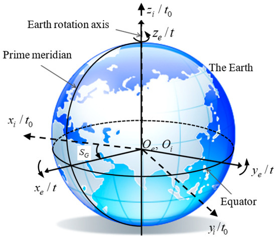 Figure 1. Definitions of earth-centered earth-fixed coordinate system and epoch earth-centered Inertial coordinate system.
 - (2)
- Epoch Earth-centered inertial (EECI) coordinate system [25]: EECI coordinate system is coincided with ECEF coordinate system at the epoch when RS begins to track NCSO (the coordinate system with the dashed line in Figure 1). Because the ECEF coordinate system rotates with the rotation of the Earth, we can let the directions of ECEF -axis and -axis at the epoch be fixed in the inertial space. They will be EECI -axis and -axis, respectively. The origin, , is also located at center of mass of the Earth, -axis is coincided with -axis of the ECEF coordinate system. EECI coordinate system does not rotate with the rotation of the Earth and its directions are fixed in the inertial space, so it is convenient to describe motion of the spacecraft or space objects.
- (3)
- Spacecraft body coordinate system [25,26]: The system is fixed with RS body (Figure 2), the origin, , resides at center of mass of the spacecraft and the three axes are three principal spacecraft body inertia axes. Specifically, -axis points to the spacecraft forward direction, which is the roll axis, -axis points to the negative normal direction of the spacecraft orbital plane and can be considered as the pitch axis, and -axis points to the center of the Earth along the radial direction, which is the yaw axis. The spacecraft body system is also a right-handed system.
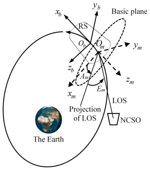 Figure 2. Definitions of spacecraft body coordinate system and space-borne radar measurement coordinate system.
 - (4)
- Space-Borne Measurement (SBM) coordinate system [25]: the system is established based on the basic plane which passes through phase center of the antenna and is perpendicular to the radar beam (Figure 2). The origin, , is located at phase center of the antenna, -axis points along to the radar beam, and -axes are on the basic plane, generally, -axis points towards the direction of -axis of the spacecraft body coordinate system, and -axis is regulated by the right-handed rule.
2.2. Coordinate System Transformation
Transformation between coordinate systems defined above are given as follows.
- (1)
- For transformation between the spacecraft body coordinate system and SBM coordinate system,where, and are the position and velocity vector of the space object in the measurement coordinate system, respectively. and are the position and velocity vectors of NCSO in the spacecraft body coordinate, respectively. Superscripts, and , indicate a differentiation in time and a matrix transpose, respectively. denotes the position vector of the measurement coordinate origin, , in the spacecraft body coordinate system. is the installation matrix, which is determined by the installation angles, including the rolling angle, , pitch angle, , and yaw angle, . According to the transformation of the order of 3-1-2 from the measurement coordinate to the spacecraft system body coordinate system [24],
- (2)
- Transformation between the ECEF coordinate system and spacecraft body coordinate system can be obtained by [24],where and are the position and velocity vectors of NCSO in the ECEF coordinate system. and holds the position and velocity vectors of RS in the ECEF coordinate system, which imply information of the orbital maneuvering of the RS. and are the attitude matrix and its derivative of the spacecraft body, which are determined by the attitude angles, including the rolling angle, φ, the pitch angle, θ, and the yaw angle, ϕ, which can be determined by the space-borne GNSS. According to the transformation of the order of 3-1-2 from ECEF coordinate system to the spacecraft body coordinate system [24],
- (3)
- As for transformation between the EECI coordinate system and the ECEF coordinate system [25,26],where, and is the space object position vector in the EECI coordinate system. and are the Earth rotation matrix and its time derivative, respectively. For the Earth rotation matrix [26],where,and is the angular velocity of the Earth’s rotation [24], is the epoch when RS begins to track a NCSO. The current EECI coordinate system is very similar to the ECI coordinate system J2000.0 [24]. Because the measurement duration is relatively short, the precession, nutation and polar shift with slow variation can be ignored between EECI coordinate system and ECEF coordinate system, and the rotation of the Earth is just needed. These simplify the transformation process between the EECI coordinate and the ECEF coordinate.
2.3. State Equation of the NCSO
To estimate the orbit of NCSO, it is necessary to estimate the position, , and the velocity, , in the EECI coordinate system. To perform the maneuvering analysis of NCSO, it is necessary to estimate the acceleration, , To set up the state equation, it is necessary to estimate the acceleration rate, . At the time, , the state vector is,
The state vector at time and state vector at time (short measurement duration) relate as follows [25]:
where, is the state noise vector, is a state transition matrix,
In the state transition matrix, is a zero matrix of order 3×3, is the unit matrix of order 3 × 3, is an error matrix of order 12×1. Let , , and are 3 × 3 diagonal matrices with diagonal elements of , , and , respectively.
According to error propagation theorem [25,27], state covariance matrix, , at time
can be mapped to time according to Equation (11),
Equation (11) is a linear equation of motion with the advantage to calculate the state transition matrix from , , and directly, and the orbit state integral is not needed. The computational expenses are greatly reduced.
2.4. Measurement Equation
When the space-borne MMW radar on RS is employed to tracking a NCSO [8], a series of observational data can be measured in SBM coordinate system at the time (as shown in Figure 2),
in which, is the distance between NCSO and RS, contains the Line-of-Sight (LOS) velocity of NCSO obtained by Doppler effect, , namely elevation, is the angle between LOS and the basic plane of the measurement coordinate system, , namely azimuth, is the angle between the x-axis and the projection of LOS on basic plane. is positive in clockwise direction [8,25]. The measurement vector can be described as the functions of and ,
Let be the initial value of the state vector, , at the time . By substituting the initial value into Equations (8) and (9), the initial position vector and initial velocity vector can be calculated in SBM coordinate system. The observational data can be computed from Equations (15)–(18), that is,
Then, Equations (15)–(18) can be linearized in a unified form with Taylor expansion [25],
where, is design matrix, is a comprehensive error for the measurement error and linearization error, and is the difference between the observational data and its computed value, is the modified state vector [25,27],
For the distance observation, and are as follows:
where the partial derivatives are derivable from Equations (8) and (15)
For the LOS velocity observation, and are as follows:
where the partial derivatives are derivable from Equations (8), (9) and (16)
For the elevation observation, and are as follows:
where the partial derivatives are derivable from Equations (8) and (17),
Finally, for the azimuth observation, and are as follows:
3. Orbit Estimation for Non-Cooperative Space Object
The orbits of NCSO can be determined employing the observational data through an extended Kalman filter [25,27].
- (1)
- (2)
- Using the observational data according to Equation (20), the state vector and its covariance matric are estimated at the time , which is called the measurement-updated.where, , , , , , and are the estimated state vector, the predicted state vector, the modified state vector, the estimated covariance matrix of state vector, the predicted covariance matrix of state vector, the measurement noise covariance matrix and the gain matrix at the time , respectively. and are the estimated state vector and the estimated covariance matrix of state vector at the time , respectively. Since the position and velocity vectors of RS are known at the time of measurement, the orbit state of NCSO can be estimated without considering RS maneuvering condition as long as NCSO is in the sight of the RS.
4. Risk Assessment for Non-Cooperative Space Object
4.1. Prediction of Shortest Distance and Encountering Time
Generally, position vector, , and velocity vector, , of RS at the measurement time, , are determined by GNSS in the ECEF coordinate system. Acceleration, , and acceleration rate, , of RS can be obtained by taking differentiation in time. Therefore, the state vector, , of RS and its covariance matrix, , can be obtained. With the estimated orbit of NCSO in the EECI coordinate system by Equation (40) to predict the minimum distance and encountering time between RS and NCSO, transformation of the RS state vector from the ECEF to the EECI coordinates is necessary. The transformation matrix between the two systems is derived as following according to Equation (5) [25]
Therefore, the position, velocity, acceleration, and acceleration rate of RS in the EECI coordinate at the measurement time,, are,
Their covariance matrix in the EECI coordinate system can be calculated by,
The estimated state vector and covariance matrix of NCSO can be calculated by Equation (40). Thus, the relative state vectors between NCSO and RS in the EECI coordinate are,
The distance between NCSO and RS can expressed as follows:
Typically, if NCSO approaches to RS in a minimal distance (or even collides), let,
then, the following equation is derived according to Equation (46),
i.e., the relative position vector and the relative velocity vector are perpendicular when NCSO approaches to RS in a minimal distance, as shown in Figure 3.
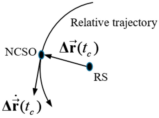
Figure 3.
The relative position vector and relative velocity vector are perpendicular in a minimal distance at the encountering time .
where is the time when NCSO is the closest to RS (let it be the encountering time), and are the relative position and relative velocity vectors at the encountering time. Referring Equation (11), and can be approximately computed by,
and,
where, is the encountering period, calculated by Newton’s iteration method. A function is constructed as,
As a result,
4.2. Collision Probability
If the estimated positions of RS and NCSO were very accurate and when the distance of the two spacecraft is close to zero, they would collide into each other. However, the measurement and calculation errors have to be accounted to evaluate the inaccuracy on RS and NCSO estimated positions. Error ellipsoid described by the position covariance matrix is employed. The spacecraft is assumed to reside inside of the ellipsoid randomly. In some cases, spacecraft contour is replaced by the error ellipsoid in the collision analysis. Collision may occur when the error ellipsoids of the two spacecraft contact with each other. In a conventional approach, the collision probability is calculated by integrating the probability density in the space of where the two error ellipsoids intersect, which is a very complex method. In the present paper, an alternative method is proposed for saving the computation power.
Chan [10] proved that if the covariance matrices of the two spacecraft position errors are not correlated, the relative position error covariance matrix is the sum of the two spacecraft position error covariance matrices. If the relative position error covariance matrix is allocated to NCSO, the relative position covariance matrix between NCSO and RS is the summation of Equations (53) and (54),
With the assumption that all the random factors are imposed on NCSO at the encountering time, , the real relative position vector is , the relative position vector which contains the random factors is , and thus the relative position error can be obtained by . Combining the covariance of relative position error , the relative position error ellipsoid of NCSO is,
Generally, =3 is chosen, consequently, the present error ellipsoid is a 3σ error ellipsoid. The relative position probability density distribution function is,
where is the determinant of a matrix. The collision probability between NCSO and RS can be calculated by integrating the probability density distribution function over the 3σ error ellipsoid,
Details of the integration method can be found in Wang and Li [13]. There is a high probability of collision when the relative position is located inside of the 3σ error ellipsoid.
4.3. Maneuvering Probability
A maneuvered spacecraft can be identified by monitoring its acceleration. Nevertheless, due to the existence of measurement and calculation errors, the estimated acceleration is not accurate. Maneuvering probability is hence employed to have a better judgement. It can be calculated by maneuvering acceleration, , and its covariance matrix, . Accounting the relative motion between NCSO and the Earth as a two-body problem, the maneuvering acceleration is derived by calculating the difference between the estimated acceleration, , from Equation (40) and two-body motion acceleration,
in which is mass of the Earth and is the gravitational constant. (39860044 ± 1) × 107 m3/s2 [23].
The probability density distribution function of the maneuvering acceleration is
where is the maneuvering acceleration variance. When the maneuvering acceleration, , falls into the error ellipsoid, the magnitude of the maneuvering acceleration is small and possibility of maneuvering is low. In other words, when it resides out of the error ellipsoid, the maneuvering acceleration is large and there is a high chance that the NSCO is under maneuvering operation. Lastly, the probability of maneuvering can be obtained by integrating the density distribution function,
The integration is made in the 3σ error ellipsoid of NCSO maneuvering acceleration, . Detailed integration approach can be read in Wang and Li [13].
5. Results and Discussion
Four sets of simulations are conducted. The first set of simulation is utilized as an example to verify the proposed algorithm, and the latter three sets of simulations are performed for further testing and statistical analysis.
For the first orbital simulation, RS and NCSO are simulated. Their initial trajectory parameters in EECI coordinate system are listed in Table 1, which is around the Earth at an approximate altitude of 1000km (i.e., low Earth orbit).

Table 1.
The initial trajectory parameters of reference spacecraft (RS) and non-cooperative space object (NCSO) in epoch Earth-centered inertial (EECI) coordinate system.
NCSO in the simulation is designed under maneuvering to approach RS. For the RS, two cases are conducted. The first case simulates RS without any maneuvering operation that it is approached by NCSO, and the second case simulates RS with maneuvers to avoid collision with the upcoming NCSO. NCSO and the RSs in both cases are simulated in an intrinsic orbit in which the spacecraft is affected by the Earth gravity and other orbit perturbations only, including the lunar, solar, and other planetary gravitational perturbations; the solar radiation pressure; and the other general relativistic forces. Orbits of NCSO and RS are illustrated in Figure 4. NCSO approaches RS from right to left and the footprint of its orbit can be observed by the black dashed curve. For the RSs in both cases, it travels from left to right. The red curve marks the trace of RS without maneuvering. With maneuvers, the orbit of RS can be observed by the blue dashed curve in Figure 4. For RS under maneuvering, the accelerations imposed on RS are described in the RTN orbit coordinate system in Figure 5. For the RTN system, the origin resides at center of mass of the spacecraft; the R-axis directs along the position vector (radial direction); the N-axis is pointing along the orbit normal vector (normal direction); the T-axis points toward velocity vector (track direction); and they complete the orthogonal triad [23].
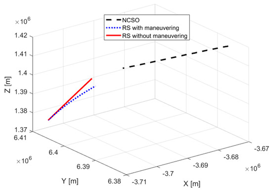
Figure 4.
Simulated orbits of NCSO and RS.

Figure 5.
Maneuvering accelerations of RS in RTN orbit coordinate system.
5.1. Orbit Estimate of NCSO
Orbit estimation for NCSO are performed in this section. With errors that may exist during the measurement processes, correlation parameters which were taken into the orbit estimation algorithms for current validation are shown in the following:
- (1)
- Since RS needs to determine its own position by GNSS, errors may exist in this process. Usually, the standard deviation of the position and velocity determined by GNSS is 10 m and 0.2 m/s [4], respectively.
- (2)
- For the errors in the measurement process, the standard deviation for measurements of distance, LOS velocity, and azimuth and elevation angle of space-borne MMW radar are 35 m, 20 m/s, and 0.45 degrees [8], respectively.
With correlation parameters introduced above, by comparing the simulated orbit and estimated orbit calculated by the algorithm that is described in Section 3, orbit errors in x-axis, y-axis, and z-axis, and total position error are shown in Figure 6. The red curve indicates the errors in the orbit estimated by the measurement data from RS without maneuvering and the blue dashed curve represent the orbit error in the case of RS under maneuvering operation. Errors in both cases tend to converge to a certain value after poor initial results. The estimated orbit in both cases agree well and differences between the two cases are small. To have quantitative comparisons, the root mean square (RMS) values of the total position error are 119.53 m and 126.29 m in the case of RS without and with maneuvering, respectively. With a closer look, one can observe that the orbital maneuvering for RS has minor but negligible effects on estimating the orbit of the NCSO. For both cases, after the poor initial results, the magnitude of the maximum position error is under 300 m.
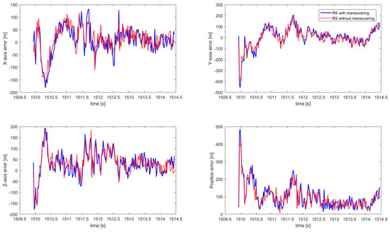
Figure 6.
Errors of NCSO estimated orbit in epoch Earth-centered inertial (EECI) coordinate system.
5.2. Prediction of Minimum Distance and Encountering Time
With the state vector of NCSO obtained above, the minimum distance between RS and the NCSO, and encountering time can be predicted. In Figure 7 and Figure 8, the predicted minimum distance and the corresponding encountering time for the two cases are plotted versus time.
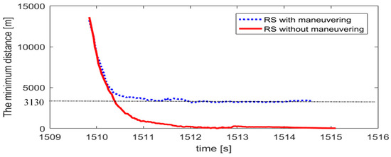
Figure 7.
Prediction of minimum distance between NCSO and RS.

Figure 8.
Prediction of encountering time with NCSO.
Measurements for NCSO starts at t = 1509.09 s. After inaccurate initial results, in the case of RS without maneuver at tk = 1510.5 s, the predicted encountering time with NCSO is tc = 1515.7 s. As time goes by, with more measurement data, the predicted encountering time converges to tc = 1515.72 s. The minimum distance between the two spacecraft is predicted to be 4.6 m. In such situation, there is a high collision probability between NCSO and RS. For the case of RS that is under orbital maneuvering, however, a predicted minimum distance is 3,130 m between NCSO and RS at time tc = 1515.55 s, and since the size of the spacecraft is much smaller than the encountering minimum distance, collision is highly unlikely to happen.
5.3. Prediction of Collision Probability
Results on the collision probability between NCSO and RS for the two cases are provided in Figure 9.
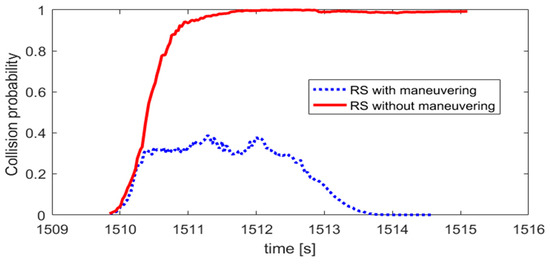
Figure 9.
Prediction of collision probability between NCSO and RS.
For RS that does not have maneuvering operations, as the measurement data accumulates, probability of collision increased to 99.99%. This agrees well with the result of predicted minimum distance, which is 4.9m in Figure 4. There is a high chance that the two objects would collide. For RS with maneuver accelerations, the probability increases on early stages with a maximum of 40%. After time t = 1512.00s when predicted encountering time converges to final result, it decreases drastically to zero which implies that the two spacecraft would not strike with each other.
5.4. NCSO Maneuvering Identification
Maneuver acceleration and maneuver probability of NCSO for the two cases are computed at different time and plotted in Figure 10 and Figure 11.
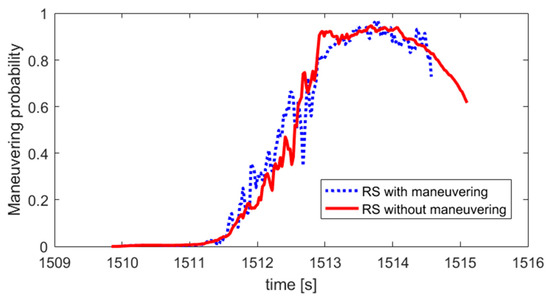
Figure 10.
Maneuvering probability of NCSO.
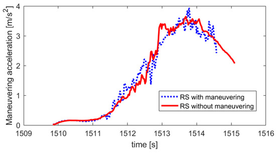
Figure 11.
Maneuvering acceleration of NCSO.
In the case of RS with no maneuvering operation, at t = 1513.7 s, the calculated maneuver probability reaches a height of 94.84% with maximum acceleration of 3.65 m/s2. Similar results are obtained in the case of RS under maneuvering, at the same time of t = 1513.7 s, and maneuver probability observed a maximum of 96.87% with the greatest maneuver acceleration of 3.95 m/s2. It can be concluded that whether or not RS is maneuvering has little effects on NCSO maneuvering identification.
5.5. More Simulated Data
In order to test the algorithms introduced in the present paper with more simulation data, three more simulations are conducted. These three simulations are identical to the first set of simulation previously employed. Nevertheless, some parameters in the simulations differ. In Figure 12, orbits of NCSO and RSs in the four simulations are presented. Orbit accelerations for the RSs under maneuver for the rest three simulations are similar to the accelerations in the first simulation.
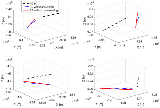
Figure 12.
Simulated orbits of NCSO and RS (four sets of simulation).
For the last three sets of simulations, results on minimum distances and collision probability between NCSO and RS, and maneuvering probability and maneuvering accelerations of NCSO are shown in Figure 13, Figure 14 and Figure 15.
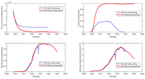
Figure 13.
Minimum distances and collision probability between NCSO and RS, and maneuvering probability and maneuvering accelerations of NCSO for second simulation.
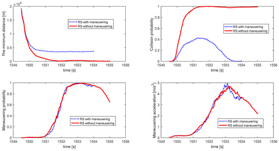
Figure 14.
Minimum distances and collision probability between NCSO and RS, and maneuvering probability and maneuvering accelerations of NCSO for third simulation.
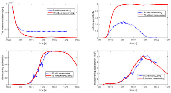
Figure 15.
Minimum distances and collision probability between NCSO and RS, and maneuvering probability and maneuvering accelerations of NCSO for fourth simulation.
For the four set of simulations, results calculated from the proposed algorithms were collected and summarized in Table 2.

Table 2.
Summary of results from the proposed algorithms.
All the results presented in Table 2 are in expectation. Compared to the results from the first set of simulation data, the last three set of results also showed a stable performance of the proposed algorithms.
6. Conclusions
The estimating algorithms of orbital maneuvering acceleration and orbital maneuver probability of NCSO are proposed. The predicting algorithms of the minimum distance and the collision probability between NCSO and RS are studied. Simulations were conducted for validating the algorithms. Some useful conclusions are summarized as follows.
- (1)
- EECI coordinate system can replace ECI to simplify coordinate transformation reasonably. Because the measurement duration is short, and the precession, nutation and polar shift with slow variation can be ignored in the process of coordinate transformation between EECI coordinate system and ECEF coordinate system.
- (2)
- The linear equation of motion of NCSO in short measurement duration make it unnecessary to integrate the motion equation to calculate the orbit, which greatly simplifies the on-orbit calculation. Moreover, compared with the conventional orbit determination method, the extended Kalman filter based on the linear equation of motion can be introduced to estimate the positions and velocities, as well as the accelerations, which is helpful to judge the orbit maneuvering of NCSO.
- (3)
- Compared with orbital maneuvering acceleration, orbital maneuvering probability can intuitively reflect the maneuvering situation of NCSO
- (4)
- RS often makes orbit maneuver to avoid collision, but RS orbit maneuverability will not affect the orbit determination and orbit maneuvering identification of NCSO based on the proposed orbit determination method and orbital maneuvering probability algorithm.
However, the accurate maneuvering acceleration should be derived by subtracting two-body motion acceleration and orbital perturbation acceleration from the estimated acceleration.
However, the accurate maneuvering acceleration should be derived by subtracting two-body motion acceleration as well as orbital perturbation accelerations from the estimated accelerations, the calculation of orbital perturbation accelerations is very complicated, the future investigations is to simplify the calculation of orbital perturbations.
Author Contributions
Y.W. conceived the idea with X.H.; Z.Y. and Q.W. verified the feasibility of the method and implemented the software algorithm, L.H. and Z.Y. analyzed the experimental result; Y.W. and L.H. wrote the first version of the manuscript. All authors have read and agreed to the published version of the manuscript.
Funding
This work is funded by the Program of National Natural Science Foundation of China (No. 41974001) and the Key Projects of Chinese National Natural Science Foundation (No. 41830110). This research was also supported by the Fundamental Research Funds for the Central Universities (grant number 2018B07414 and B200202006).
Acknowledgments
We would like to thank the anonymous reviewers and member of the editorial team for their comments and contributions.
Conflicts of Interest
The authors declare no conflict of interest.
References
- Tu, W. Research on Tracking of Maneuvering Spatial Target; Shanghai Jiao Tong University: Shanghai, China, 2012. [Google Scholar]
- Junkins, J.L.; Akella, M.R.; Alfriend, K.T. Non-Gaussian error propagation in orbital mechanics. J. Astronaut. Sci. 1996, 44, 541–563. [Google Scholar]
- Alfriend, K.T.; Yan, H. Evaluation and Comparison of Relative Motion Theories. J. Guid. Control Dyn. 2012, 28, 254–261. [Google Scholar] [CrossRef]
- Wen, Y.L.; Wang, W.; Yang, Y.X. Study on the relative problem of GPS-based geometric orbit determination in real time. Chin. Space Sci. Technol. 2001, 2001, 43–48. [Google Scholar]
- Davis, G.W. Exploring the Limits of GPS-Based Precise Orbit Determination. Navigation 1997, 44, 183–193. [Google Scholar] [CrossRef]
- Wu, S.C.; Yunck, T.P.; Thornton, C.L. Reduced-dynamic technique for precise orbit determination of low earth satellites. J. Guid. Control Dyn. 2012, 14, 2143–2153. [Google Scholar] [CrossRef]
- Yunck, T.P.; Wu, S.C.; Wu, J.T. Precise tracking of remote sensing satellites with the Global Positioning System. IEEE Trans. Geosci. Remote Sens. 1990, 28, 108–116. [Google Scholar] [CrossRef]
- Liu, B. Space Object Orbit Prediction Based on Spaceborne Radar. Chin. J. Space Sci. 2010, 30, 532–539. [Google Scholar]
- Qiu, H.X.; Zhu, Z.M.; Wu, L.D. Study of collision analysis method for spacecraft. J. Astronaut. 2005, 26, 257–261. [Google Scholar]
- Chan, K. Collision probability analyses for earth orbiting satellites. Adv. Astronaut. Sci. 1997, 96, 1033–1048. [Google Scholar]
- Bérend, N. Estimation of the probability of collision between two catalogued orbiting objects. Adv. Space Res. 1999, 23, 243–247. [Google Scholar] [CrossRef]
- Morselli, A.; Armellin, R.; Lizia, P.D.; Zazzera, F.B. A high order method for orbital conjunctions analysis: Monte Carlo collision probability computation. Adv. Space Res. 2015, 55, 311–333. [Google Scholar] [CrossRef]
- Wang, H.; Li, H.Y.; Tang, G.J. General method for calculating spacecraft collision probability. J. Natl. Univ. Def. Technol. 2006, 28, 27–31. [Google Scholar]
- Wang, H.; Tang, G.J.; LI, H.Y. Collision Probability Based Trajectory Safety in Close Range Guidance Phase of Rendezvous and Docking. J. Astronaut. 2007, 28, 648–652. [Google Scholar]
- Bai, X.Z.; Chen, L. Explicit expression and influencing factor analysis of collision probability between space objects. Chin. J. Space Sci. 2009, 29, 422–431. [Google Scholar]
- Cheng, T.J.; Wang, R.; Yu, Y. Collision probability analysis and application of cataloged space debris. Chin. J. Space Sci. 2006, 26, 452–458. [Google Scholar]
- Jeongahn, Y.; Malhotra, R. Simplified Derivation of the Collision Probability of Two Objects in Independent Keplerian Orbits. Astron. J. 2017, 153, 1–11. [Google Scholar] [CrossRef]
- Lee, D.; Cochran, J.E.; Jo, J.H. Solutions to the Variational Equations for Relative Motion of Satellites. J. Guid. Control Dyn. 1971, 30, 669–678. [Google Scholar] [CrossRef]
- Lane, C.M.; Axelrad, P. Formation Design in Eccentric Orbits Using Linearized Equations of Relative Motion. J. Guid. Control Dyn. 2006, 29, 146–160. [Google Scholar] [CrossRef]
- Huang, J.; Hu, W.; Zhang, L. Maneuver Detection of Space Object for Space Surveillance. In Proceedings of the 6th European Conference on Space Debris, Darmstadt, Germnay, 22–25 April 2013. [Google Scholar]
- He, J. The Maneuvering Detection Based on Wavelet transfoRmation; Taiyuan University of Technology: Taiyuan, China, 2007. [Google Scholar]
- Li, C.B. Research on Sliding—Window Target Maneuver Detection Algorithm Based on Input Estimation; Nanjing University of Science and Technology: Nanjing, China, 2010. [Google Scholar]
- Xu, G.; Yan, X. Perturbed Orbit and Its Determination; Springer: Berlin, Germany, 2016. [Google Scholar]
- Markley, F.L.; Crassidis, J.L. Fundamentals of Spacecraft Attitude Determination and Control; Springer: Berlin, Germany, 2014. [Google Scholar]
- Liu, G.M.; Liao, Y.; Wen, Y.L. Passive Tracking Technology of Non-Cooperrative Space Target and Application; National Defense Industry Press in China: Beijing, China, 2015. [Google Scholar]
- Montenbruck, O.; Gill, E. Satellite Orbits: Models, Methods and Applications; Springer: Berlin, Germany, 2001. [Google Scholar]
- Yang, Y.X.; Wen, Y.L. Synthetically adaptive robust filtering for satellite orbit determination. Sci. China Ser. D 2004, 47, 585–592. [Google Scholar] [CrossRef]
© 2020 by the authors. Licensee MDPI, Basel, Switzerland. This article is an open access article distributed under the terms and conditions of the Creative Commons Attribution (CC BY) license (http://creativecommons.org/licenses/by/4.0/).