1. Introduction
Pile positioning is an important and difficult task for piling construction, especially for the tilted pile in the sea. Normally for offshore piling construction, the position deviation measured at the cut-off level should be less than 10 cm for straight plies and 20 cm for tilted piles. The traditional method for offshore positioning piling uses the intersection of lines of sight with two or three theodolites. The third theodolite is used to verify the direction of the other two lines of sight and improve the positioning accuracy. A survey engineer then guides the pilling ship according to the estimated distance between the sight and the pile edge (
Figure 1). However, this method has limits on piling efficiency and position accuracy in real-time piling positioning. For instance, the estimated distance is not accurate and thus it is hard to assist the piling ship movement.
Global Navigation Satellite Systems (GNSS) and Real-time Kinematic GNSS (RTK GNSS), especially high precision GPS positioning, make real-time automatic positioning possible. Using RTK GPS can deliver real-time equipment positioning with high precision [
1] and monitor the deformation of the bridge [
2,
3,
4]. In hazardous environments, RTK GNSS also allows safe and effective navigation for autonomous robots [
5,
6]. GNSS also plays an important role for positioning in construction [
7,
8]. Stent Foundations Ltd. launched their Stent Automatic Pile Positioning and Recording System (SAPPAR), which comprises several kinds of sensors: one RTK GNSS, one two-axis vertical sensor, and one flux-gate compass. All the data from sensors are gathered and processed for auto-piling rig positioning [
9]. Hui developed a real-time guidance information system for marine pier construction [
10].
Processing images captured from a CCD camera can also help to obtain the position and other movement information of an object. A reliable vision positioning method using two cameras to dock an Autonomous Underwater Vehicle (AUV) was shown to be successful in the general deep-water pool lab of Harbin Engineering University [
11]. Li proposed a high precision 3D indoor positioning method and achieved accurate 3D positioning by one or two reference points in a scene, and by the sensors from the smart phone, which have camera and orientation-sensors [
12]. Danilo introduced a methodology to measure the velocity of a rigid object in a linear motion with the use of a sequence of images acquired by a commercial digital camera [
13].
A real-time pile positioning system was developed using four RTK GNSS, two laser rangefinders and one 2D tiltmeter [
14,
15]. The system significantly improved the production and efficiency and had a good performance in the piling engineering of the longest cross-sea bridge, the Donghai Bridge in Shanghai, China.
In addition, the CCD camera was also used to measure the real-time displacement of a flexible bridge with digital image processing techniques [
16]. The penetration per hammering is an important parameter for sea piling and the use of a CCD camera was shown to give an opportunity to extract this data accurately from the continuous processing of pile images. That is the other important reason for using a CCD camera in sea piling.
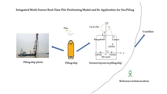
In this paper, an updated real-time pile positioning model for sea piling, using an integrated sensory system was described. The sensory system included four RTK GNSS receivers (one of them is used as reference station), one CCD camera, one laser rangefinder, and one 2D tiltmeter. The direction of the laser rangefinder needs to be calibrated to make sure it achieves precise alignment with the X axis after installation. The CCD camera was used to obtain the direction from the perspective center to the pile edge, which is represented by the dotted line in
Figure 2. The coordinate of the circle pile’s center coordinate was then obtained by two parameters which were the direction from the CCD camera and the distance between the laser rangefinder and the pile. The location of all sensors is shown in
Figure 2.
This paper is divided into two parts. The first part introduces the roles of GNSS positioning, the pile positioning model together with an integrated sensory system and how to extract the pixel difference between two images captured before and after hammering. In the second part, the pile position model is applied in a case study. The results are then discussed focusing on the accuracy and reliability of the proposed algorithm.
2. Pile Positioning Model with the Integrated Sensory System and Pixel Distance Extraction Algorithm
2.1. Real Time Piling Ship and Sensors Positioning by GNSS RTK Technology
GNSS RTK technology is used to obtain the real time positions, directions and altitudes of the piling ship and sensors in three steps:
Step 1: Set up the GNSS reference station on a point on shore whose coordinate is precisely known.
Step 2: Obtain the real time coordinates of other 3 GNSS receivers, which are installed on the piling ship and their locations are shown in
Figure 2.
Step 3: Attain the real time coordinates for the rangefinder and CCD camera according to the mutual positional relationship among the 3 GNSS rovers.
The pile foundation project is about serval kilometers far away from the shore, whose surrounding is very spacious and no buildings block the GNSS signal. GNSS RTK is also a mature technology with high positioning precision, hence it is very suitable for obtaining the piling ship’s position, direction, and altitude using the data collected from three GNSS rovers on the piling ship.
GNSS data collection and processing software are developed by the third author’s organization, which is the College of Surveying and Geoinformatics, Tongji University in Shanghai, and the output is the real-time coordinate time series of three GNSS rovers with a GPGGA format, which is managed by the National Marine Electronics Association, that defines the interface between various pieces of GNSS devices. It includes essential fix data which provide accuracy 3D location, and then the coordinates of other sensors on the piling ship are determined.
Figure 3 shows a diagram of using the GNSS RTK positioning technology for a piling foundation project near the shore.
2.2. Real Time Pile Positioning Model
This chapter focus on real time pile positioning, according to the sensors installed on piling ship.
Figure 4 describes the relevant directions and angles of the CCD camera. Firstly, the direction from the CCD camera perspective center to the pile edge needs to be determined for the positioning model, and it is defined as the angle μ which is defined as can be seen in
Figure 4, μ =
β −
φ.
The pile positioning model includes four steps.
Step 1: Measuring angle μ.
Step 2: Building a standard positioning model, assuming all the exterior orientation angle elements of the camera are zero and the pile is upright—i.e., the pile edge in the image is also vertically upright.
Step 3: Considering the influence of the exterior orientation angle elements of the camera and the tilt of the pile to update the standard positioning.
Step 4: Obtaining the coordinates of the pile center in the construction coordinate system by the coordinate transformation.
Figure 5 below shows the data processing flowchart of the CCD camera and laser rangefinder.
2.2.1. Measuring Angle μ
- (1)
Exterior Orientation Angle Elements of the CCD Camera
There are three exterior orientation angle elements (
φ,
ω,
k) of the CCD camera; angles
φ and
ω define the direction of the prime optical axes in the spatial coordinate system of an object, and angle
k indicates the rotation angle of the light beam relative to the prime optical axis. The spatial coordinate system of images is a right-hand coordinate system and, for the ease in obtaining solutions and three small angle elements, Ship Fixed Coordinate System (SFCS:
O −
XYZ) and Ship Fixed Photogrammetry Coordinate System (SFPCS:
S −
X′
Y′
Z′) were established, as shown in
Figure 6.
Figure 7 gives detailed information for the perspective center and exterior orientation angle elements.
S is the perspective center;
p is the image;
o is the principal point of the photograph;
Se′ is the projection of the principal ray on the
S −
X′
Z′ plane;
Sn is the projection of
Se′ on the negative
Z′ axis;
o −
XY is the coordinate system of the image.
Figure 8 shows three views about three exterior orientation angle elements of the camera.
Figure 8a shows the exterior orientation angle
φ.
Figure 8b shows the exterior orientation angle
ω.
Figure 8c shows the exterior orientation angle
k. which is the rotation angle of the prime optical axis in the plane
S −
X′
Z′.
Before installing the CCD camera on the piling ship deck, it needs to be calibrated to obtain the interior orientation elements and distortion coefficient. Then, the exterior orientation elements can be solved with the method of single image space resection after the CCD camera is installed on the deck.
- (2)
Extracting the Straight Line of the Pile Edge from Captured Image by the CCD Camera
Three steps are taken to extract the straight line of the pile edge. Firstly, an edge detection algorithm is used distinguish the edge from the rest of an image. Then, a clear edge is obtained from a binary image according to a suitable threshold. Finally, the straight-line extraction algorithm is employed to obtain the parameters of the edge line.
Since the pile movement is limited within an area, a processing area is predefined to save computational time. As for the images where the pile edge is clear and nearly vertical, Roberts’ cross operator algorithm [
17] is suitable to detect the edge and Hough’s transformation algorithm [
18] is used to attain the line parameters (
Figure 9).
The solution for the angle between the prime optical axis and the direction of the pile edge is simple when the exterior orientation angles are zero and the pile is upright; it is given by:
where
xe is the pile edge pixel coordinate on the x-axis,
x0 is the principal point pixel coordinate on the x-axis, and
f is the focal length.
xe and
β can be obtained based on the calculated straight-line equation of the pile edge (
ρ =
x cos θ +
y sin θ).
2.2.2. Standard Positioning Model
Standard modeling only considers an upright pile and assumes the three exterior orientation angles of the CCD camera, being zero; it is described as follows:
The known data include:
- (1)
Laser rangefinder coordinates (XR, YR, ZR) of SFCS and measured distance l.
- (2)
Internal and external elements of the CCD camera (f, x0, y0, φ, ω, k, XS, YS, ZS).
- (3)
Angle μ between the X axis and the direction of pile edge which is the tangential to the pile.
Two parameters which are the coordinates of the ellipse’s center (Xe, Ye) need to be calculated. They can be achieved using the known information of the point in the ellipse XR + L, YR and of the direction of the pile edge from the CCD camera.
2.3. Revised Positioning Model
2.3.1. Revised Modeling for Tilted Pile
The tilted pile solution is similar to the upright pile, but some parameters need revising, as discussed below.
- (I)
Revised long radius of ellipse: , where n is the slope ratio and r is the radius of the pile.
- (II)
Revised height difference between the CCD camera perspective center and rangefinder: The measured value
l from the laser rangefinder should be corrected as
where
l is the measured value from the rangefinder;
ZS is the height of the CCD;
ZR is the height of the rangefinder.
2.3.2. Revised Modeling for Exterior Orientation Angle Elements
- I.
Taking the negative angle φ to be left deviation as an example to demonstrate the influence of the angle φ. The slope of the tangent from the perspective center to the pile edge should be revised as K′ = tan(φ + β).
Figure 10a shows the pile image with exterior orientation angle elements of zero.
o is the principal point of the photograph. Bold oblique lines represent the two edges of the pile (similar in the following figures).
Figure 10b shows the image influenced by the angle
φ and the pile position in the image moves right, compared to
Figure 10a.
- II.
Influence of angles
φ and
ω (taking a positive angle
ω to be upward deviation as an example):
Figure 10c,d illustrate the same condition but from different views.
Figure 10c, which is from a side view, shows the image
p with angle
ω of zero, while image
p1 is influenced by non-zero angle
w and
Figure 10d shows the influence by the angle
ω from front view.
- III.
Influence of angles
φ,
ω and
k (taking a positive clockwise angle
k as an example):
Figure 10e shows that the image influenced by three exterior orientation angels and three dotted line segments in
Figure 10e are the same as in
Figure 10d.
After making clear the influence by the three exterior orientation angles of the camera, the standard pile position model can be revised and then obtain the right coordinate of the pile center.
2.4. Pixel Distance Extracted with SIFT Algorithm
The Scale Invariant Feature Transform (SIFT) algorithm can detect the same points between the two images with better performance, although one of the images may be rotated, zoomed, or moved [
19,
20].
Figure 11 shows that many of the same points were detected by SIFT, even if Image 2 changes significantly.
The pile image after hammering is moved down to compare to the original one. Hence, the SIFT algorithm is used to find the same points in two images before and after hammering.
Figure 12a and
Figure 12b are the images captured by the CCD camera before and after one hammering, respectively. It is obvious that the pile is sinking after hammering, and
Figure 12c shows that many of the same points have been detected by SIFT, and then the sinking pixel distance can be calculated.
3. Case Study
Figure 13 is the piling ship used in this case study, “Yangshanhao”. All sensors mentioned above were installed on the ship’s deck and their positions are shown in
Figure 2. In order to verify the accuracy and reliability of the positioning model, results obtained from the pile positioning model were verified against Liu [
14] who obtain the pile center coordinate by two rangefinders and other sensors.
As we can see from the
Figure 14, the CCD camera, which is placed to the right to avoid being blocked by the ship’s equipment, and two rangefinders are enclosed in the instrument box.
All of the sensors used for this case study are listed in
Table 1. Interior orientation elements and the external orientation elements of the CCD camera are listed in
Table 2. Two rangefinder coordinates in SFCS and their measured values are listed in
Table 3. The pile information and the detected straight line parameters (ρ, θ) are listed in
Table 4. Three kinds of combinations and their calculated results for the pile center are listed in
Table 5.
There are differences between three combinations given in
Table 5, and there are several reasons for them. For instance, the piling ship was not completely static in the water and this limited the measuring accuracy of the CCD camera exterior orientation element. In addition, the measured value from the rangefinder also contained an error. However, differences of about 3 cm show that the use of one rangefinder and one CCD camera for solving pile center coordinates is an acceptable solution.
Positioning results of eighty piles were verified through comparing the solutions achieved with the combination of rangefinder 1 and camera and the combination of rangefinder 1 and rangefinder 2 (as ground truth). The eighty piles include forty straight piles and forty tilted piles, and they are used to check the positioning performance of this proposed approach.
Figure 15 and
Figure 16 show the solution differences between two combinations in the X and Y directions of the straight piles and tilted piles. From the two figures, we can observe if the accuracy of straight piles positioning is better than tilted piles. The difficulty to get the slanting line parameters for the tilted pile edge is the possible reason and this causes more error. We can also find that the accuracy in the X direction is better than that of the Y direction, which means that we can rely on a high-quality laser rangefinder to get accuracy positioning for one direction.
The distances between the positions attained with two combinations are also verified and we find that the accuracy of straight piles positioning is better than that of tilted piles from
Figure 17 and
Figure 18.
Figure 19 shows the main interface of the software using the positioning model and the integrated sensory system which were introduced in this paper.
4. Discussion
A novel solution to model for the offshore piling with an integrated sensors system is discussed in this paper. The sensors system utilized four RTK GNSS receivers, one tiltmeter, one rangefinder, and one CCD camera. By using one rangefinder and one CCD camera, and throughly developing relevant algorithms to consider the influence of the tilted pile and the exterior orientation angle elements, the pile center positioning model was shown to give acceptable real-time predictions via a practical case study.
Considering the instability of the interior orientation elements of non-metric CCD cameras, the camera needs to be calibrated regularly without moving the camera in the special conditions of a piling ship. Moreover, an advanced algorithm to measure pile penetration per hammering, using a different technique to pixel distance, will be researched in the future work.
5. Conclusions
A combination of GNSS and other sensors can be used to precisely resolve the piling positioning issue within the special operational environment, and this paper presents a solution for the offshore piling project, especially using the contactless method consisting of a laser rangefinder and a CCD camera, as this provides more possibilities for positioning.
In this paper, the standard pile positioning model built for an integrated sensory system was introduced, and then how to remove the influence of exterior orientation angle elements was discussed. Finally, according to the experiment and case study, the new method was thoroughly verified.
Although this pile positioning model has relatively small group users, we have tried to explore its potential in other applications, especially for the large cross-sea infrastructure positioning in the deep sea. For example, we have developed the software to implement the rig positioning of oil drilling platforms and the movement guiding of the riprap-throwing ships for the embankment protection. Thanks to the rapid development of sensor technology, the combination of GNSS with other sensors may become more widely used to address various offshore construction positioning and other related issues.
Author Contributions
Conceptualization, Y.X., X.M. and L.Y.; methodology, Y.X. and Q.W.; software, Y.X. and Q.W.; validation, L.Y. and Y.Y.; writing—original draft preparation, Y.X.; writing—review and editing, X.M.; experiment, Y.X. and L.Y.; supervision, X.M.; All authors have read and agreed to the published version of the manuscript.
Funding
This study was supported by the Shanghai Education Commission Research and Innovation Project (No. 10ZZ25).
Acknowledgments
Thanks to SIPG (Shanghai International Port Group) for providing the piling ship and facilities. We also would like to thank all of reviewers and editors for their very constructive comments and hard work to ensure the quality of this paper.
Conflicts of Interest
The authors declare no conflict of interest.
References
- Peyret, F.; Betaille, D.; Hintzy, G. High-precision application of GPS in the field of real-time equipment positioning. Autom. Constr. 2000, 9, 299–314. [Google Scholar] [CrossRef]
- Meng, X.; Dodson, A.; Roberts, G. Detecting bridge dynamics with GPS and triaxial accelerometers. Eng. Struct. 2007, 29, 3178–3184. [Google Scholar] [CrossRef]
- Yu, J.; Meng, X.; Yan, B.; Xu, B.; Fan, Q.; Xie, Y. Global navigation satellite system-based positioning technology for structural health monitoring: A review. Struct. Control Health Monit. 2020, 27, e2467. [Google Scholar] [CrossRef]
- Yu, J.; Yan, B.; Meng, X.; Shao, X.; Ye, H. Measurement of bridge dynamic responses using network-based real-time kinematic GNSS technique. J. Surv. Eng. 2016, 142, 04015013. [Google Scholar] [CrossRef]
- Seward, D.; Pace, C.; Agate, R. Safe and effective navigation of autonomous robots in hazardous environments. Auton. Robot. 2007, 22, 223–242. [Google Scholar] [CrossRef]
- Chen, H.; Moan, T.; Verhoeven, H. Safety of dynamic positioning operations on mobile offshore drilling units. Reliab. Eng. Syst. Saf. 2008, 93, 1072–1090. [Google Scholar] [CrossRef]
- Roberts, G.; Dodson, A.; Ashkenazi, V. Global positioning system aided autonomous construction plant control and guidance. Autom. Constr. 1999, 8, 589–595. [Google Scholar] [CrossRef]
- Cai, H.; Andoh, A.R.; Su, X.; Li, S. A boundary condition based algorithm for locating construction site objects using RFID and GPS. Adv. Eng. Inform. 2014, 28, 455–468. [Google Scholar] [CrossRef]
- Seward, D.; Scott, J.; Dixon, R.; Findlay, J.; Kinniburgh, H. The automation of piling rig positioning using satellite GPS. Autom. Constr. 1997, 6, 229–240. [Google Scholar] [CrossRef]
- Tserng, H.-P.; Han, J.-Y.; Lin, C.-T.; Skibniewski, M.; Weng, K.-W. GPS-Based real-time guidance information system for marine pier construction. J. Surv. Eng. 2013, 139, 84–94. [Google Scholar] [CrossRef]
- Li, Y.; Jiang, Y.; Cao, J.; Wang, B.; Li, Y. AUV docking experiments based on vision positioning using two cameras. Ocean Eng. 2015, 110, 163–173. [Google Scholar] [CrossRef]
- Li, H. Single and double reference points based high precision 3D indoor positioning with camera and orientation-sensor on smart phone. Wirel. Pers. Commun. 2015, 83, 1995–2011. [Google Scholar] [CrossRef]
- Filitto, D.; Hasegawa, J.K.; Polidório, A.M.; Martins, N.A.; Flores, F.C. Real-time velocity measurement to linear motion of a rigid object with monocular image sequence analyses. J. Real-Time Image Process. 2016, 11, 829–846. [Google Scholar] [CrossRef][Green Version]
- Liu, C.; Yao, L. RTK GPS based sea piling engineering: Mathematical model and its application. Surv. Rev. 2007, 39, 193–202. [Google Scholar] [CrossRef]
- Yao, L.; Xie, Y.; Ji, H. Piling position model and its implementation based on intelligent total station. J. Tongji Univ. (Nat. Sci.) 2010, 8, 1123–1127. [Google Scholar]
- Lee, J.-J.; Shinozuka, M. Real-time displacement measurement of a flexible bridge using digital image processing techniques. Exp. Mech. 2006, 46, 105–114. [Google Scholar] [CrossRef]
- Shrivakshan, G.; Chandrasekar, C. A comparison of various edge detection techniques used in image processing. Int. J. Comput. Sci. Issues (IJCSI) 2012, 9, 269–276. [Google Scholar]
- Fisher, A.L.; Highnam, P.T. Computing the Hough transform on a scan line array processor (image processing). IEEE Trans. Pattern Anal. Mach. Intell. 1989, 11, 262–265. [Google Scholar] [CrossRef][Green Version]
- Ng, P.C.; Henikoff, S. SIFT: Predicting amino acid changes that affect protein function. Nucleic Acids Res. 2013, 31, 3812–3814. [Google Scholar] [CrossRef] [PubMed]
- Ke, Y.; Sukthankar, R. PCA-SIFT: A more distinctive representation for local image descriptors. In Proceedings of the 2004 IEEE Computer Society Conference on Computer Vision and Pattern Recognition (CVPR), Washington, DC, USA, 27 June–2 July 2004. [Google Scholar]
Figure 1.
Traditional method for pile positioning of offshore piling.
Figure 1.
Traditional method for pile positioning of offshore piling.
Figure 2.
Pile positioning diagram.
Figure 2.
Pile positioning diagram.
Figure 3.
GNSS RTK (Real Time Kinematic) positioning technology for piling foundation project diagram.
Figure 3.
GNSS RTK (Real Time Kinematic) positioning technology for piling foundation project diagram.
Figure 4.
Direction and angle associated with CCD camera.
Figure 4.
Direction and angle associated with CCD camera.
Figure 5.
Processing flowchart of the CCD camera and rangefinder data.
Figure 5.
Processing flowchart of the CCD camera and rangefinder data.
Figure 6.
Ship Fixed Photogrammetry coordinate system and Ship Fixed coordinate system.
Figure 6.
Ship Fixed Photogrammetry coordinate system and Ship Fixed coordinate system.
Figure 7.
Auxiliary image spatial coordinate system.
Figure 7.
Auxiliary image spatial coordinate system.
Figure 8.
Three exterior orientation angle elements of the CCD camera. (a) Vertical view-angle φ; (b) Side view-angle ω; (c) Front view-angle k.
Figure 8.
Three exterior orientation angle elements of the CCD camera. (a) Vertical view-angle φ; (b) Side view-angle ω; (c) Front view-angle k.
Figure 9.
Image from the camera and extraction of the straight line of the pile edge.
Figure 9.
Image from the camera and extraction of the straight line of the pile edge.
Figure 10.
Influence of the three exterior orientation angles of the CCD camera: (a) Image of all exterior orientation angle elements zero; (b) Image influenced by angle φ; (c) Side view-image influenced by angle w; (d) Front view-image influenced by angles φ and w; (e) Image influenced by angles φ, w and k.
Figure 11.
Same points detected by SIFT with two different images.
Figure 11.
Same points detected by SIFT with two different images.
Figure 12.
Same points detection from two images before and after hammering: (a) Image before hammering; (b) Image after hammering; (c) Detected same points from two images.
Figure 12.
Same points detection from two images before and after hammering: (a) Image before hammering; (b) Image after hammering; (c) Detected same points from two images.
Figure 13.
Piling ship “Yangshanhao”.
Figure 13.
Piling ship “Yangshanhao”.
Figure 14.
Rangefinders and CCD camera installed on the ship’s deck.
Figure 14.
Rangefinders and CCD camera installed on the ship’s deck.
Figure 15.
Solution difference between two combinations in X and Y directions for straight piles.
Figure 15.
Solution difference between two combinations in X and Y directions for straight piles.
Figure 16.
Solution difference between two combinations in X and Y directions for tilted piles.
Figure 16.
Solution difference between two combinations in X and Y directions for tilted piles.
Figure 17.
Positional difference between two combinations for straight piles.
Figure 17.
Positional difference between two combinations for straight piles.
Figure 18.
Positional difference between two combinations for tilted piles.
Figure 18.
Positional difference between two combinations for tilted piles.
Figure 19.
Software main interface using multi-sensor integration positioning model.
Figure 19.
Software main interface using multi-sensor integration positioning model.
Table 1.
All of the sensors used for the case study.
Table 1.
All of the sensors used for the case study.
| Name | Brand | Model | Number |
|---|
| GNSS | Trimbe | 5700 | 4 |
| Tiltmeter | Lamshine | AT201-SC | 1 |
| Rangefinder | Dimetix | DLS-B30 | 2 |
| CCD camera | IKENO | IK-204 | 1 |
Table 2.
The interior and exterior orientation elements of the CCD camera.
Table 2.
The interior and exterior orientation elements of the CCD camera.
| CCD Coordinate of SFCS (m) | Exterior Orientation Angle Element (Radian) | Interior Orientation Element (Pixel) |
|---|
| X | Y | Z | α | ω | κ | f0 | x0 | y0 |
| −30.769 | −0.330 | 0.117 | −0.037212 | −0.047235 | −0.006217 | 2672.21 | 385.02 | 242.54 |
Table 3.
Coordinates and the measured value of two rangefinders.
Table 3.
Coordinates and the measured value of two rangefinders.
| | X Coordinate (m) | Y Coordinate (m) | Z Coordinate (m) | Measured Value (m) |
|---|
| Rangefinder1 | −30.752 | −0.229 | 0 | 5.8458 |
| Rangefinder2 | −30.752 | 0.221 | 0 | 5.9226 |
Table 4.
Pile and detected line parameters.
Table 4.
Pile and detected line parameters.
| | Pile Diameter (m) | Pile Slope Ratio | Detected Line ρ (Pixel) | Detected Line θ (Radian) |
|---|
| Information | 1.2 | 6 | 193 | 0.01745 |
Table 5.
Calculated results of three combinations.
Table 5.
Calculated results of three combinations.
| | Pile Center X(m) | Pile Center Y(m) |
|---|
| Rangefinder1 and Camera | −36.989 | −0.019 |
| Rangefinder2 and Camera | −37.022 | −0.020 |
| Rangefinder1 and Rangefider2 | −37.003 | −0.052 |
© 2020 by the authors. Licensee MDPI, Basel, Switzerland. This article is an open access article distributed under the terms and conditions of the Creative Commons Attribution (CC BY) license (http://creativecommons.org/licenses/by/4.0/).


