1. Introduction
Underground mining often causes ground subsidence at surface [
1,
2,
3,
4,
5,
6]. Under certain assumptions, the rate and extent of ground subsidence can be predicted in advance [
7,
8,
9] and mitigation measures can be implemented in a timely manner [
10,
11,
12]. In the case of the Berezniki Potash Mine 1 (Berezniki-1), it was assumed that the structural integrity of the impermeable layer of rock, known as waterproof formation, located between the ceiling of the topmost mined seam and the base of the lowermost aquifer, could be preserved indefinitely and ground subsidence contained.
The Verkhnekamskoe salt deposit is located in the central part of the Solikamsk depression of the Pre-Ural Foredeep. The 135 × 40 km deposit is represented by a 500 m thick salt stratum with an 80 m thick layer of potassium-magnesium salts in its upper part. The average thickness of the productive sylvinite zone is 20 m. The salt stratum, being an aquiclude, divides the groundwater into two hydrogeological levels, above and below the salt layer. The entire stratum above the salt layer, with the exception of a few insignificant drained areas, is completely saturated with water. The discharge zone of the underground waters of this aquifer complex is the Kama river and its inflows. Currently, potash salts of the Verkhnekamskoye deposit are extracted at six mines and two more are under construction. The main feature of the field development is the need to preserve the water impermeability of the waterproof formation. In order to ensure the protection of mines from flooding, a chamber development system is used at the deposit, in which the overlying stratum of rocks is supported by regularly installed interchamber pillars.
The Verkhnekamskoe salt deposit that hosts Berezniki-1 has been mined since the 1930s. It is one of the largest potash mines in Russia, with a total mined-out volume since 1930 of more than 80 million cubic meters. The city of Berezniki has been built above the underground mine primarily to support the mining operation; it is the second-largest city of Perm Krai, Russia with a current population of 150,000. Ground subsidence caused by mining operations has long been observed in Berezniki but its rate remained low. One of the largest accidents in the world practice of water-soluble ore mining occurred on 17 October 2006, when the structural integrity of the Berezniki-1 mine was breached, resulting in water intrusion (with rates reaching 1200 m
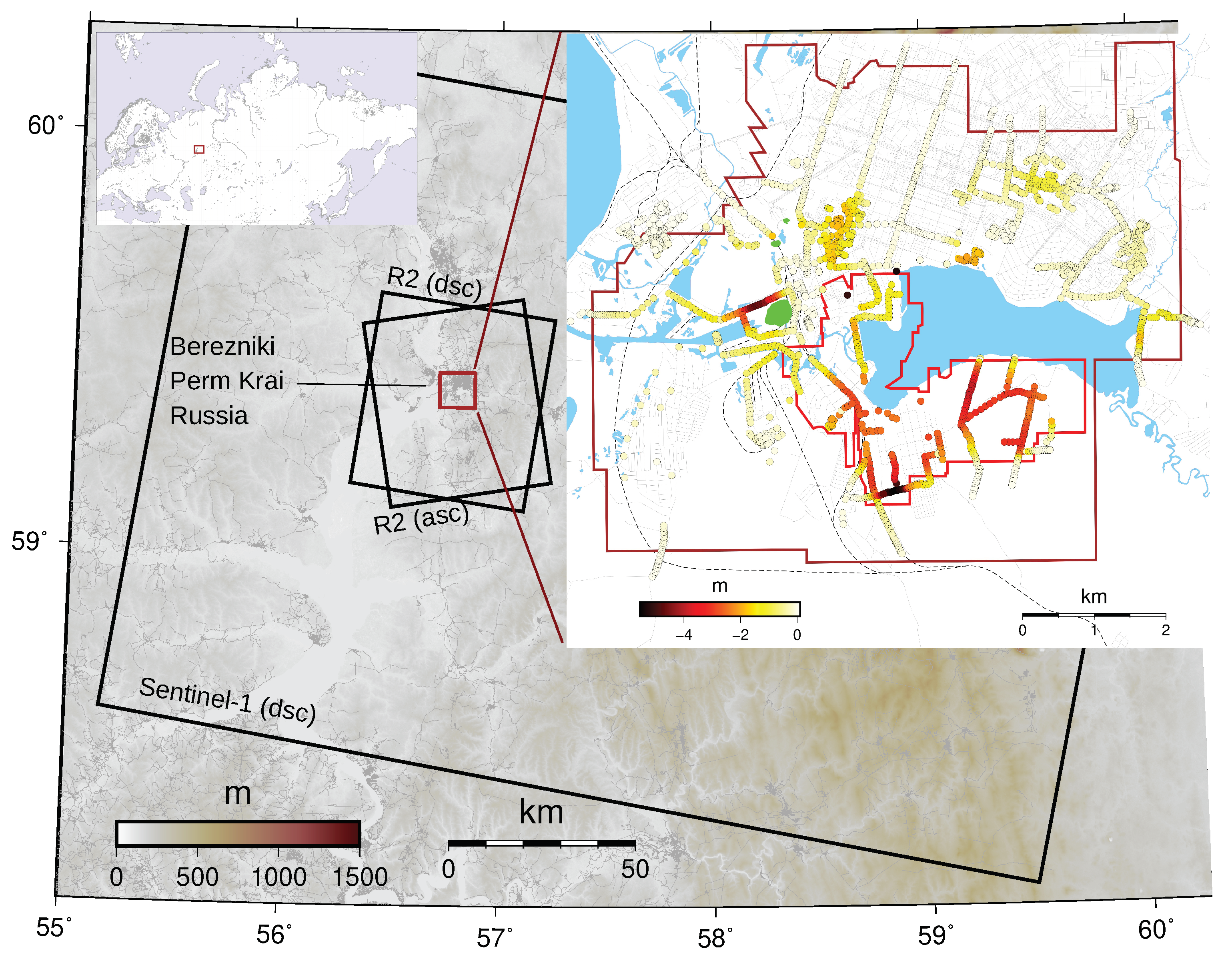
/h) and subsequent flooding and closure of the mine. The subsidence rate increased dramatically and at least five sinkholes were formed within the city area in the following years. The largest (440 × 320 m) sinkhole was formed on 28 July 2007 in the area where water intrusion occurred (green polygons in the insert of
Figure 1). It was followed by smaller sinkholes on 25 November 2017 (70 × 120 m, 90 m deep), 4 December 2011 (130 × 140 m, 75–80 m deep), 17 February 2015 and 9 April 2017. The sinkholes were initially of smaller size but they continued to grow until eventually stabilized. The first and largest sinkhole is presently flooded and the second sinkhole has been filled in. The sinkholes were preceded by rapid (at least 20 cm/month) localized subsidence that began in 2016.
The extent of the mining operations of carnallite (KCl · MgCl · 6H
O, seam B) and sylvinite (or potash, a mixture of sylvite KCl and halite NaCl, seam Kr II) [
13] are shown in
Figure 1. The 8–10 m thick carnallite seam is located above the 5–7 m thick sylvinite seam and these seams are mined at a depth of 250–300 m. When flooded with fresh or lightly mineralized water, sylvinite dissolves until its solution is saturated with NaCl and KCl salts. The carnallite seam is located at higher elevations. When it dissolves, a brine saturated with MgCl
is formed. It is heavier and, accordingly, sinks pushing up brine saturated with NaCl and KCl, which in turn dissolves the carnallite rocks, becoming saturated in Mg by crystalizing the NaCl and KCl salts. This results in a convective dissolution process. Thus, in the areas where water can access carnallite and sylvinite, the dissolution process will continue and, accordingly, high rates of subsidence at the surface will continue [
14,
15].
The ground subsidence in the city has been monitored using a precise leveling technique since at least 2012 and over 5.5 m of subsidence have been measured (
Figure 1). At several locations, subsidence has exceeded 10 m. While precise leveling can potentially achieve high measurement precision, it is performed only once or twice per year and only along profile lines. Such measurements are therefore limited in spatial coverage and temporal resolution.
Remote sensing measurements of subsidence using Differential Interferometric Synthetic Aperture Radar (DInSAR) [
16,
17] has been performed at least since 2006 using ENVISAT and TerraSAR-X data [
18,
19]. These studies utilized standard DInSAR and Persistent Scatter Interferometry (PSI) [
20] techniques and for the first time showed a broader extent of subsidence beyond that measured by precise leveling. Very large rates of subsidence were observed in 2008 (about 100 cm/year) and 2010 (about 20 cm/year). It is likely that subsidence had continued throughout the entire time period, but no time series of ground deformation was shown in Ashrafianfar et al. [
19]. They concluded that the PSI technique produced less accurate results because the very rapid subsidence was not properly resolved.
In our study, we also utilize DInSAR to measure an extent and a rate of subsidence at the Berezniki-1 potash mine. We exploit the high-resolution RADARSAT-2 SAR data acquired during the period October 2011–April 2014 and the moderate resolution Sentinel-1 SAR data acquired during the period July 2016–June 2020. These data are processed with the Multidimensional Small Baseline Subset (MSBAS) software [
21,
22] to produce one dimensional (1D, line-of-sight) and two dimensional (2D, east and vertical) time series of ground deformation and linear deformation rates. We compare our remote sensing measurement with the current ground leveling measurements and provide recommendations on an optimal monitoring strategy.
2. Data and Methodology
In this study we used the following satellite SAR data (
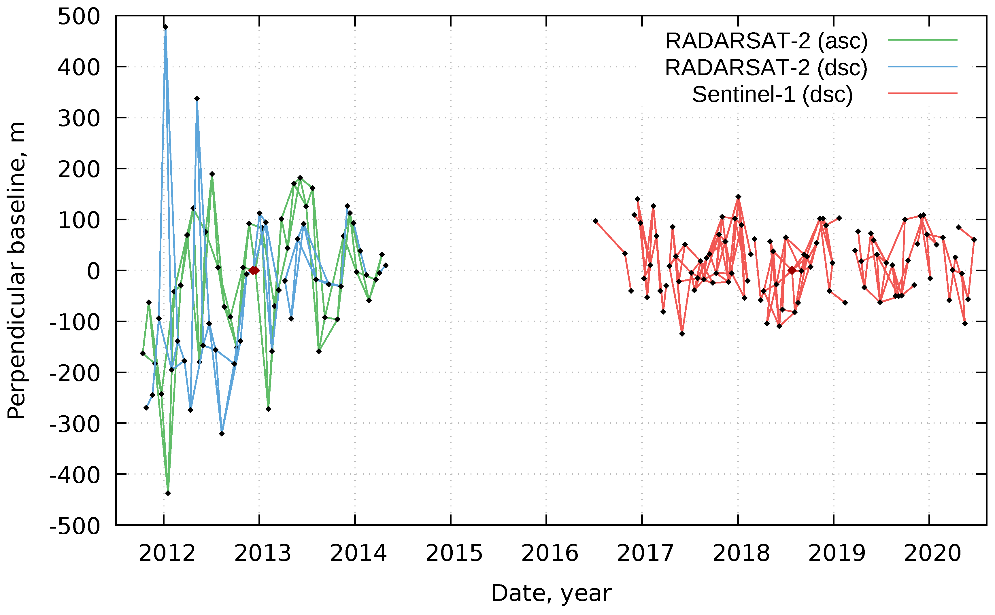
Table 1): 37 ascending and 34 descending Ultra Fine Wide RADARSAT-2 images acquired during the period October 2011–April 2014 with 24 days revisit cycle and 96 descending Interferometric Wide Swath Sentinel-1 images acquired during the period July 2016–June 2020 with 12 days revisit cycle. No ascending Sentinel-1 data was available for this region and no data at all was available between April 2014 and July 2016 (
Figure 2). Each SAR data set was processed independently with GAMMA software [
23] as follows. A single master image for each set was selected and the remaining images were re-sampled into the master geometry. We used 4 in range and 4 in azimuth multi-looking (i.e., spatial averaging) for RADARSAT-2 interferograms and 4 in range and 1 in azimuth for Sentinel-1 interferograms. The topographic phase was removed using the 30 m resolution Shuttle Radar Topography Mission [
24] Digital Elevation Model. Differential interferograms were filtered using adaptive filtering with a filtering function based on local fringe spectrum [
25], and unwrapped using the minimum cost flow algorithm [
26]. The residual orbital ramp was corrected by applying a baseline refinement algorithm implemented in GAMMA software. The atmospheric errors were not corrected since there is no reliable technique that can be used for such purpose over this small area. The spatial resolution of current atmospheric models is tens of kilometres. Instead, we relied on the least-square solution built into our processing software that naturally minimizes temporally uncorrelated atmospheric errors. Minor interpolation of each interferogram was performed in order to improve spatial coverage reduced by decorrelation and a mean coherence mask (0.4 for RADARSAT-2 and 0.57 for Sentinel-1, coherence values are after filtering) was applied to remove incoherent pixels.
Ascending and descending interferograms were geocoded and resampled using the Geospatial Data Abstraction Library (GDAL) (
https://gdal.org/) scripts to a common lat/long grid with a uniform spatial sampling of 15 m for RADARSAT-2 and 25 m for Sentinel-1 interferograms. The MSBAS technique was applied to ascending and descending RADARSAT-2 sets to produce east and vertical deformation time series and linear deformation rates, and to the descending Sentinel-1 set to produce line-of-sight (LOS) deformation time series and linear deformation rate. MSBAS software uses the singular value decomposition to reconstruct ground deformation time series from heterogeneously acquired SAR data. When ascending and descending data are provided, MSBAS computes east and vertical ground deformation time series. When only one set, either ascending or descending, is provided, MSBAS computes a LOS ground deformation time series. Linear deformation rates are then computed by fitting a line to the deformation time series. During MSBAS processing, the reference point is selected as followed. During the first MSBAS run, the reference point was selected by the system using the minimal Z-score algorithm [
22]. This allowed determining areas that are stable. Then, during the second MSBAS run, the reference point was selected manually within the previously determined stable areas and in the proximity to the area of interest. This allowed to further improve measurement precision that decreases with the distance from the reference point.
For regularizing a rank-deficient condition, the Tikhonov regularization is implemented. The network of Sentinel-1 interferograms in our case is partially disconnected (
Figure 2). In classical Small Baseline Subset (SBAS), a disconnected network may cause erroneous results. In MSBAS this issue is addressed by introducing an additional constraint. The first or second-order Tikhonov regularization minimizes the difference between consecutive velocities (first-order) or accelerations (second-order), which fills “gaps” due to the partially disconnected network. If certain interferogram is fully disconnected (i.e., master and slave images are disconnected) from the rest of the network, then it can be eliminated as it does not add any additional information about the cumulative displacement [
22]. In this study, the first-order regularization with
equal to 0.1 was used.
For comparison with the RADARSAT-2 and precise leveling results, the Sentinel-1 interferograms were divided by a constant value of the cosine of the incidence angle, producing pseudo-vertical deformation time series and linear deformation rates. In this computation, it was assumed that the contribution from horizontal components is negligible. Then, Sentinel-1 pseudo-vertical observations were extracted at pixels in the proximity of the precise leveling profile lines and the correlation coefficient between Sentinel-1 pseudo-vertical deformation rates and 2018–2019 vertical deformation rates from precise leveling was computed.
The ground-based precise leveling data used in this study consists of a cumulative vertical deformation, starting from 2012 and vertical deformation rates in the period 2018–2019.
3. Results
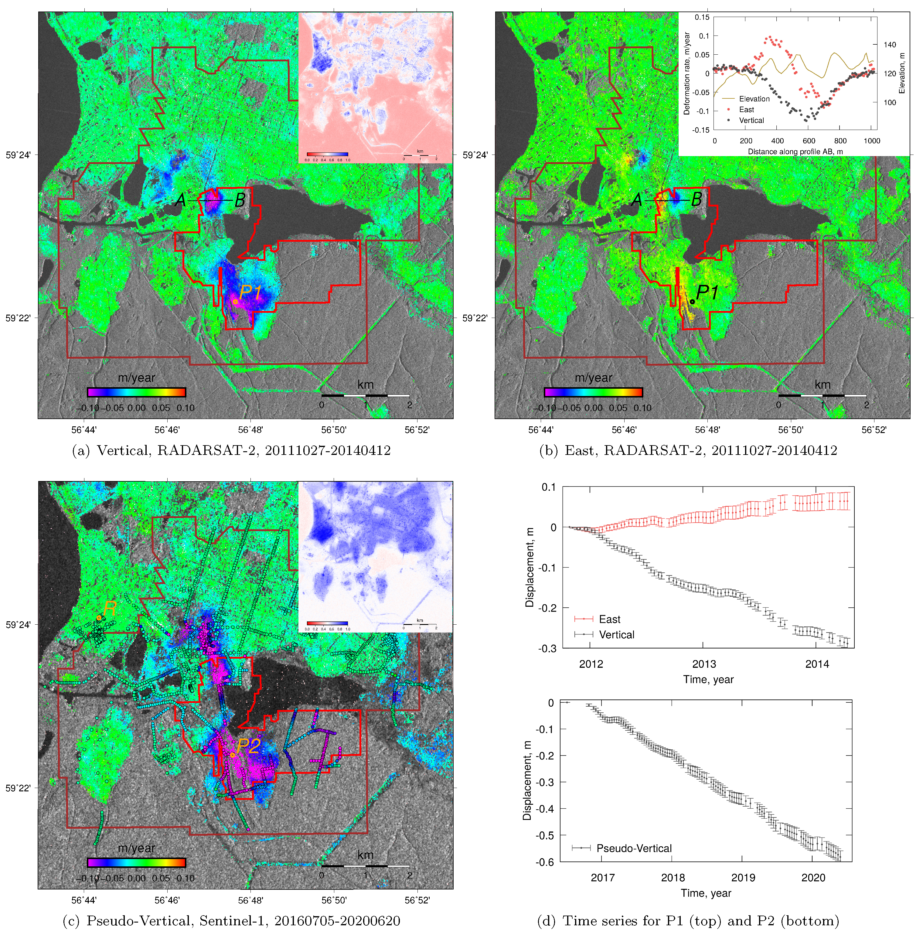
The results of MSBAS processing are shown in
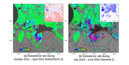
Figure 3. During the period October 2011–April 2014 the observed subsidence was concentrated in three regions (
Figure 3a). Two regions with the fastest subsidence of up to 14 cm/year are located where both carnallite and sylvinite are mined (red and brown polygons, respectively). The third region of subsidence is located to the west where the only sylvinite is mined. Horizontal deformation with a rate of up to 10 cm/year was also observed during this time (
Figure 3b). The deformation pattern is, as expected, to the east on the western side of the subsidence bowl and to the west on the eastern side of the subsidence bowl (profile AB in
Figure 3b). Some areas remain incoherent, exposing the satellite intensity image in the background. The standard deviation of vertical and horizontal deformation rates are 1.6 and 1.1 cm/year, respectively.
During the period of July 2016–June 2020, the area affected by subsidence is observed to be larger (
Figure 3c). The two regions with the fastest subsidence are also located where both carnallite and sylvinite are mined and where subsidence has been observed in prior years. However, the northern subsidence area extends beyond the carnallite seam and merges with the third area located to the west. Here the maximum pseudo-vertical deformation rate reaches 17 cm/year, while the standard deviation for the entire region is 2.4 cm/year. The results of precise leveling along profile lines are shown as small circles with a black outline and are filled with a colour similar to the DInSAR results colour scale. Visually, there appears to be good agreement between the pseudo-vertical July 2016–June 2020 deformation rate from Sentinel-1 and the 2018–2019 vertical rate from precise leveling although the leveling profiles extend beyond the areas covered by DInSAR. In particular, precise leveling shows fast subsidence to the east of the large southern subsidence observed by DInSAR, which is still within the area where both carnallite and sylvinite are mined. Several smaller areas of subsidence are observed on the periphery and some of them are have been confirmed by precise leveling.
The time series of ground deformation for two characteristic regions are shown in
Figure 3d. For the 5 × 5 pixels (approximately 80 × 80 m) region P1, time series are shown for the period October 2011–April 2014. Approximately 30 cm of subsidence and 8 cm of eastward motion occurred during this period. Some variability in the subsidence rate is observed, with rates during 2013 and 2014 winter being slightly lower. For the 5 × 5 pixels (approximately 140 × 140 m) region P2, time series are shown for the period July 2016–June 2020. Approximately 60 cm of subsidence occurred during this period at a steady rate. Error bars in the time series capture variability within the 5 × 5 pixels window. They do not account for the low-frequency noise, due to atmospheric disturbances and residual orbital ramp that may be present in individual interferograms.
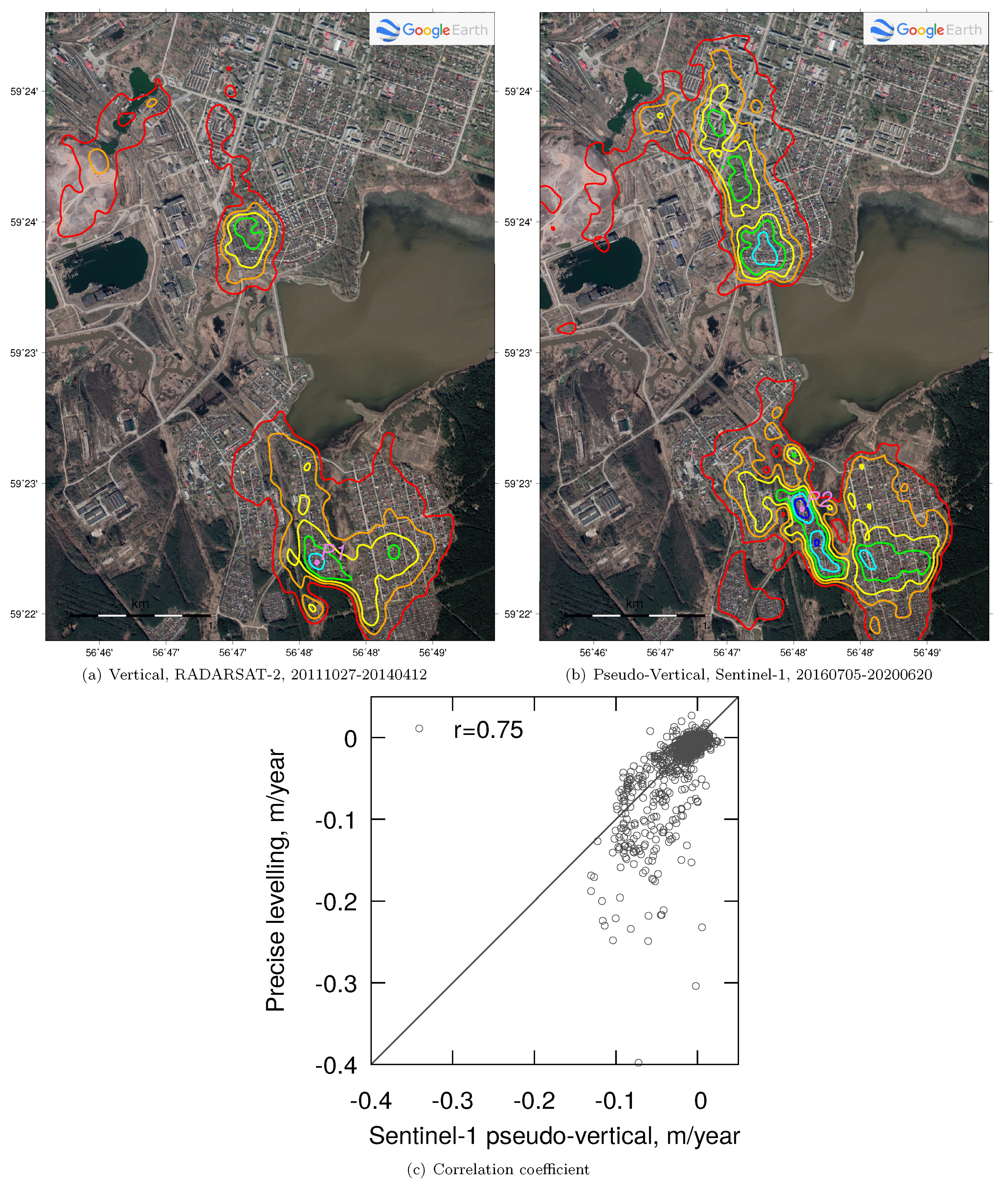
Subsidence rates during the two studied periods (
Figure 3a–c) were further filtered using the 2D low-pass spatial filter with the Gaussian weights and the 200 m (six sigmas) window and plotted as colour-coded contour lines over the high-resolution optical image from Google Earth Pro (
Figure 4a,b).
The results of correlation analysis between the pseudo-vertical July 2016–June 2020 deformation rate from Sentinel-1 and the 2018–2019 vertical rate from precise leveling are shown in
Figure 4c. The correlation coefficient is 0.75, suggesting that the results from space-borne and ground-based measurements are in good agreement. Sentinel-1 data somewhat underestimates the subsidence rate in comparison to precise leveling. The discrepancy is likely due to (I) horizontal components of deformation distort the pseudo-vertical Sentinel-1 deformation rates, (II) some Sentinel-1 interferograms are not properly unwrapped due to very low coherence and fast deformation gradient, and (III) noise present in both data sets.
4. Discussion and Conclusions
In this study, we measured the intensity of ground subsidence above a flooded potash mine under the city of Berezniki (Perm Krai, Russia) using RADARSAT-2 and Sentinel-1 Synthetic Aperture Radar data. This area has experienced very rapid subsidence since October 2006 when the integrity of the Berezniki-1 mine was compromised, resulting in the closure of the mine. High rates of subsidence are observed in areas of mining of carnallite and sylvinite. The sylvinite seam is separated from the overlying thick carnallite seam by layers of rock salt. The carnallite seam itself consists of carnallite layers and rock salt layers. In some areas of sylvinite mining, the overlying carnallite layer is exposed due to the collapse of the roof of the chambers made of rock-salt rocks. This starts the process of dissolution of carnallite seam by brine saturated with NaCl and KCl, which causes an increase in the subsidence rate. In addition to rapid subsidence, at least five sinkholes have formed in the region, with the largest being 440 × 320 m.
In
Figure 4a,b, the subsiding region can be subdivided into two zones, northern and southern. Historically, in the northern zone, at the time of the accident (2006), the maximum subsidence was observed in the place of a freshwater intrusion (the area of formation of the largest sinkhole). After the formation of the largest sinkhole (2007), subsidence propagated further north, where later other sinkholes were formed. During that time, the subsidence rate there reached 18–20 cm/month. After the full flooding of the mine (end of 2008), the subsidence rate decreased by an order of magnitude. In 2010, after the formation of two additional sinkholes in this area, the subsidence rate increased again, approximately to the present level. This increase is attributed to the beginning of the dissolution of the overlying carnallite rocks. In the southern zone, where the carnallite seam was mined without filling the extraction chambers with waste material, the development of subsidence began much later (2012). The average subsidence rate was 5–7 cm/month and was due to the dissolution of carnallite rocks. This process continues to this day.
Ground subsidence and sinkholes have significantly affected the city of Berezniki located above the flooded mine. In residential areas, subsidence has caused the destruction of residential dwellings and in industrial areas the destruction of industrial facilities and infrastructure, including water and gas pipelines. Residents of affected buildings were relocated but the risk of damage to industrial plants remains. The railroad was also significantly damaged by subsidence and sinkholes and had to be rerouted. Since extraction of carnallite and sylvinite in this region will continue for decades as both minerals are in increasing demand, it is important to realize that subsidence and sinkholes will also likely continue. To minimize risk, residential and industrial infrastructure should be relocated away from the mine.
The advantages and disadvantages of each monitoring technique are clear from our results. While precise leveling achieves very high measurement precision, it is limited in the spatial extent to a few profile lines and in temporal resolution to annual or semi-annual observations; it is also expensive. DInSAR measurements have higher temporal (currently about 12 days) and spatial (2–100 m) resolutions, but they are affected by the decorrelation in the densely vegetated areas in this region. For example in
Figure 4a,b) in the southern zone, the red contour line that marks 2 cm/year subsidence outlines the boundaries of developed areas. Without precise leveling measurements, the full extent of subsidence would not be resolvable particularly in non-urban areas with dense vegetation. Without DInSAR measurement the extent of subsidence would not be resolvable beyond a few profile lines. The currently available Sentinel-1 SAR data are of very high quality and free, making it particularly suitable for deformation extent analysis. However, the fast deformation gradient is not well resolved by medium and low-resolution DInSAR [
27]. Therefore, it is not recommended to derive conclusions about the maximum rate of subsidence from DInSAR measurements alone. Very fast localized subsidence in this area has been reported but it has not been captured by either DInSAR or precise leveling due to the previously described measurement limitations. Since DInSAR LOS measurements are composed of vertical and horizontal components of deformation, in certain geometries they can cancel each other [
5]. To mitigate this measurement blindness, it is recommended to always analyze ascending and descending DInSAR data simultaneously, using 2D processing software, such as MSBAS [
22].
An important advantage of our methodology is the ability to measure the horizontal east component of the ground deformation when both, ascending and descending, data are available (i.e., RADARSAT-2 data during the period 27 October 2011–12 April 2014). This measurement directly characterizes the level of anthropogenic load on buildings and infrastructure. Comparing the measured values of horizontal deformation with the maximum permissible values, it is possible to draw conclusions about the threat level to buildings and infrastructure resulting from the observed deformation. Unfortunately, in this region, Sentinel-1 data are acquired only on the descending pass. Continuous Global Navigation Satellite System (GNNS) monitoring [
28,
29,
30] can also be implemented in this region if a higher temporal resolution of all three deformation components is required.
