Article

An Image-Based Real-Time Georeferencing Scheme for a UAV Based on a New Angular Parametrization

by
Ehsan Khoramshahi
1,2,*,
Raquel A. Oliveira
1,
Niko Koivumäki
1 and
Eija Honkavaara
1
1
Department of Remote Sensing and Photogrammetry of the Finnish Geospatial Research Institute FGI, Geodeetinrinne 2, FI-02430 Masala, Finland
2
Department of Computer Science, University of Helsinki, FI-00014 Helsinki, Finland
*
Author to whom correspondence should be addressed.
Remote Sens. 2020, 12(19), 3185; https://doi.org/10.3390/rs12193185
Submission received: 12 August 2020 / Revised: 23 September 2020 / Accepted: 27 September 2020 / Published: 29 September 2020

Abstract

:
Simultaneous localization and mapping (SLAM) of a monocular projective camera installed on an unmanned aerial vehicle (UAV) is a challenging task in photogrammetry, computer vision, and robotics. This paper presents a novel real-time monocular SLAM solution for UAV applications. It is based on two steps: consecutive construction of the UAV path, and adjacent strip connection. Consecutive construction rapidly estimates the UAV path by sequentially connecting incoming images to a network of connected images. A multilevel pyramid matching is proposed for this step that contains a sub-window matching using high-resolution images. The sub-window matching increases the frequency of tie points by propagating locations of matched sub-windows that leads to a list of high-frequency tie points while keeping the execution time relatively low. A sparse bundle block adjustment (BBA) is employed to optimize the initial path by considering nuisance parameters. System calibration parameters with respect to global navigation satellite system (GNSS) and inertial navigation system (INS) are optionally considered in the BBA model for direct georeferencing. Ground control points and checkpoints are optionally included in the model for georeferencing and quality control. Adjacent strip connection is enabled by an overlap analysis to further improve connectivity of local networks. A novel angular parametrization based on spherical rotation coordinate system is presented to address the gimbal lock singularity of BBA. Our results suggest that the proposed scheme is a precise real-time monocular SLAM solution for a UAV.

Graphical Abstract

1. Introduction

Unmanned aerial vehicles (UAVs) are energy-efficient observers with a high degree of freedom. Miniaturized UAVs have recently played an important role in the aerial mapping ecosystem [1,2]. Modern UAVs are equipped with a wide range of sensors and receivers such as optical sensors, e.g., red green blue (RGB) cameras, miniaturized hyper-spectral sensors, global positioning receivers, e.g., a global navigation satellite system (GNSS), orientation sensors such as an inertial measurement unit (IMU), and light detection and ranging (Lidar) sensors [3].
Real-time trajectory estimation of a UAV is essentially a micro task for many advanced applications, e.g., smart city [4], emergency [5] or agricultural and forestry [6]. Smart city applications mainly include tasks that require quick access to 3D geometric or also spectrometric information, such as near real-time mapping [7], traffic monitoring [8], individual object tracking [9], smart car parking management [10], parks and green spaces management [11], crime-scene investigation [12], harbor monitoring, etc. Agricultural and forestry applications mainly deal with biomass estimation [13], classification and monitoring tasks [14], such as forest inventory [15], forest disease investigation and monitoring [16], farm monitoring [17], crop classification and monitoring [18]. We may point to important factors such as novel advancements in UAV hardware, algorithms, and availability of new low-cost sensors that have led to the recent increase in UAV applications. Many commercial UAV models nowadays have acceptable flight durability for most urban and forestry applications. They are usually equipped with autopilot systems that ease the operation of a drone in complex situations [19].
UAV trajectory and image positions and orientations could be directly estimated by employing observations from high-grade GNSS receivers and IMU sensors when an accurate link between a camera and GNSS/IMU (lever-arm vector and bore-sight angle) is a priori known. However, image processing is an important alternative that provides positions and orientations in a local coordinate system [20]. The role of image processing is highlighted in situations where other approaches fail due to technical problems such as the existence of noise, unavailability of satellites, or multipath errors in low altitudes. In those scenarios, an automatic real-time estimation of image-based trajectory could be employed as an important alternative.
Data processing in a UAV mapping solution usually starts after images acquisition to produce the fastest possible outputs [3]. Large piles of images are gradually transferred to a photogrammetric processing unit to produce geometric or radiometric outputs. The whole process is usually a resource-hungry operation that needs hours to days of processing time that mainly depends on factors such as size of the area, requested precision level, and project-specific demands such as customized postprocessing steps. Results are finally expressed as products such as point clouds and radiometrically calibrated orthomosaics. Recent advancements in 5G communication, along with cloud computing, have already provided a suitable base for real-time UAV mapping [21]. An influential factor in a UAV solution is the computational time that limits the applicability of UAVs for cases where fast outputs are required. In a photogrammetric solution, usually a trade-off between computational time and accuracy exists that is often managed based on a project’s requirements. Several civil applications of UAVs gradually demand real-time or close to real-time outputs that have led to research and development of real-time solutions as an active research area. In a cloud-based solution, lightweight calculations are usually assigned to a UAV’s onboard computer, while heavier computations are performed in a cloud [22,23].
In a classic aerial photogrammetric solution, a conditional independency exists among 3D object points when status (positions and orientations) of images are given [24]. The object points are usually referred to as the structure, and camera status is regarded as motion. Under the assumption that a camera motion is unknown, positions of 3D points become correlated. This correlation is the main tool to estimate the camera status. Monocular simultaneous localization and mapping (SLAM) as a classic image-processing problem aims to estimate the trajectory of a single-eye observer based on 3D object point correlations. Estimating the 3D trajectory of a projective camera only by 2D image points is an interesting and complex task. This complexity multiplies when interior orientation parameters (IOP) of a projective camera are not a priori known. Historically, the first solutions to address this problem were limited to the conditions where simple solvers were employed to generate accurate estimations for exterior orientation parameters (EOP). Progress in direct relative orientation solutions (8-point algorithm and normalized 8-point algorithm [25], Nister’s 5-point algorithm [26]) and direct georeferencing [27]) has significantly improved the above situation by providing accurate initial location and orientations of images.

1.1. Feature Extraction and Matching Review

Feature extraction and matching is one of the core components of an image-based SLAM. Image matching has been recently progressed by distinctive presentations of image points, for example, Lowe [28] proposed a method for localizing points that were relatively invariant to scale and orientation (key points). He expressed his approach based on four steps. In the first step, he proposed creating a scale-space by using Difference of Gaussian (DoG) operator to detect extrema, then a model was fit to candidate key points locations (localization). Next, orientations were assigned to each key point (rotation invariance). Finally, image gradients were saved as a descriptor vector. Lowe called his approach scale invariant feature transform (SIFT). Most SIFT implementations generally consist of two phases: key point localization, and descriptor computation. Although the first implementation of SIFT was successful, it was demonstrated as a computationally heavy module; moreover, it required a considerable amount of random-access memory (RAM) for a medium-size image (>20 MPix.). Many researchers have continued Lowe’s original work by proposing solutions that were able to address the computational burden and accuracy. For example, Ke and Sukthankar [29] applied principle component analysis (PCA) on normalized gradient patches to build more distinctive descriptors. Wu [30] proposed a relatively fast implementation of SIFT by employing a graphic processing unit (GPU); he called his approach SIFT GPU. Guoshen and Morel [31] improved SIFT by incorporating six-parameters affine transformation (ASIFT). Bay et al. [32] proposed a method called speed up robust feature (SURF) by approximating DoG by box filters, since convolution with rectangular filters were much faster; therefore, their method was quicker than initial approaches of SIFT, and also required less memory. SURF localization was based on the geometric distinctiveness of features; for example, operators such as blobs, T-junctions, and corners (by Harris corner detector) have been used to localize distinctive points. They offered a “scale-invariant only” version which was more distinctive and even faster (upright SURF or U-SURF). Rosten and Drummond [33] employed a decision tree classifier to boost edge detection. They termed it their “machine-learning based” key point detector feature from accelerated test (FAST). They demonstrated that their localization approach was approximately 30 times faster than SIFT. They claimed that in some cases, their proposed feature detector outperformed the others. As a complement to the slow and memory-hungry SIFT, Calonder et al. [34] proposed a descriptor based on employing binary strings. They employed Hamming distance to compare two descriptors. They demonstrated that their proposed descriptor was “fast to build and match”. Their proposed method was called “binary robust independent elementary feature (BRIEF)”. Rublee et al. [35] combined FAST and BRIEF, thereby creating the oriented FAST and rotated BRIEF (ORB) method. They demonstrated that their approach was at two orders of magnitude faster than SIFT. Later, some researchers exposed the aforementioned techniques to a diverse set of variables and compared them. For example, Juan and Gwon [36] compared SIFT, PCA-SIFT, and SURF. They demonstrated the slowness of SIFT compared to the others, while SIFT’s performance was superior in some cases. They concluded that the choice of a suitable method mainly depended on the application. Karami et al. [37] compared the performance of SIFT, SURF, and ORB against affine translation, fish-eye-like distortion, and shearing. They showed that ORB was the fastest, while SIFT resulted in better outcomes.

1.2. Image-Based SLAM Approaches

Image-based SLAM is a technique of sensor localization and object reconstruction by taking advantage of multi-image measurements. Image-based SLAM and all its variants have been widely studied. Monocular SLAM is a sub-category of image-based SLAM that deals with SLAM algorithms that are suitable for a single camera. We may categorize monocular SLAM algorithms in two groups: 1—the algorithms that predict the status of an incoming image by employing previous observations and then adjust the predicted status by cooperating observations, and 2—the algorithms that directly employ observational equations to estimate the status of an incoming image. Here, we selectively review a small portion of recent literature based on the individual work’s closeness to our problem. A more comprehensive review of monocular SLAM could be found for example in Wu [38]. Williams et al. [39] proposed a monocular SLAM based on a loop closure algorithm. They compared “image to image” and “image to map” techniques. Steffen and Förstner [40] discussed challenges in a real-time trajectory estimation problem and proposed a solution based on initialization, loop detection and exploration strategies. Galvez-López and Tardo [41] proposed an algorithm that used a stack of key points computed by “BRIEF+FAST” for visual place recognition (in their notation: a bag of words). Their work has successfully laid the foundation of a monocular SLAM (ORB-SLAM). Mur-Artal et al. [42] proposed a single-camera SLAM (ORB-SLAM) that was able to perform all major SLAM duties including feature tracking, loop-closing and adjustment. Their proposed method was real-time and robust to noise. Fink et al. [43] proposed an image-based algorithm to estimate UAV position and linear velocity. They combined inertia data and visual SLAM to robustly predict UAV position. Jiang et al. [44] proposed an algorithm for oblique images based on structure from motion (sfm) to acquire accurate orientations and positions in a case of large volume oblique images with high overlaps. They demonstrated that their customized sfm had a linear computational cost. Chen et al. [45] used monocular SLAM (ORB-SLAM) which was combined with GNSS data in a combinatory model to estimate the trajectory.

1.3. Novel Aspects of this Article

Direct-georeferencing and image-based reconstruction are two alternative overlapping scenarios to estimate position and orientation of images. Based on our understanding, recent developments such as [39] and [40] have successfully constructed a roadmap for image-based solutions for different capturing scenarios. In this work, we aim to improve the recent trend by proposing a novel real-time monocular SLAM solution. Strictly speaking, we follow a similar methodology as those expressed by [39] and [40] in detecting loops; we modify the logic of these works based on analyzing overlaps of aerial images. Finally, a real-time monocular SLAM is presented that suitably addresses an aerial case where the object is near planar. The recent methods, such as ORB-SLAM are often used in applications where a high frequency of images is collected, for instance, using video cameras. Additionally, the resolution of the images has to be low as the processing would overload memory and speed. Typically, in high-accuracy UAV forest or agriculture mapping applications, using RGB or multispectral cameras, the flight data collection is performed with large overlaps of usually 80% and 60% or more in forward and side directions, respectively, and the images are acquired, for example, every two seconds. This is currently a more complicated scenario for the real-time SLAM approaches. Our image-matching scheme improved the computational complexity of methods discussed in Section 1.1 by introducing a multilevel pyramid matching scheme mixed with sub-window propagation and matching. We propagated the position of sub-windows on one image to the immediate neighboring image and so on. The proposed scheme was designed with the goal to reduce the computational complexity of high-resolution image-matching, while keeping the accuracy and completeness of a full-size image matching. The general structure of this work is a discussion about techniques to reduce the processing time of an aerial monocular SLAM. A novel angular parametrization based on a spherical rotation coordinate system is also implemented in this article, that addresses the gimbal lock singularity problem. A sparse bundle block adjustment (BBA) is finally introduced by employing the novel angular parametrization. The BBA was customized to incorporate GNSS and IMU observations whenever these data are available. Our results suggest that a real-time and robust monocular SLAM is accessible based on the current state-of-the-art image-matching technologies.

2. Background

2.1. Coplanarity and Collinearity

Two types of correspondence between “image points” and “object points” are used as the main observational equations: coplanarity and collinearity [46]. Coplanarity equations state that an ideal object point, its corresponding image points, and focal centers of cameras lie in a hypothetical plane under the assumption that image distortions and noises are removed. Coplanarity is initially used to connect two images by employing at-least five common image points in a stereo pair (unknown sensor case). Collinearity equations state that an image point, a focal center, and a corresponding object point lie on a line [46]. Collinearity plays an important role after initiating a network structure by coplanarity. Coplanarity deals with a stereo pair in comparison to the collinearity that allows for multi-image adjustment.

2.2. Automatic Feature Extraction and Matching

Automatic image-matching is the process of finding common image tie points between a set of images. The objective of an ideal tie point matching is to extract a correct and accurate set of matches with high repeatability that evenly covers the surface of a set of images. Existence of even a few outliers could affect the convergence of the BBA where L 2 norm is the target of the optimization. A robust image matching approach ensures that a sequential set of images will be linked with an acceptable level of accuracy.
Three main factors are important in studying and employing any image-matching algorithm: 1—accuracy, 2—repeatability, and 3—timing. Since the first outcome of any matching approach may result in many false matches, the outlier filtering has a key role. Several outlier removal preprocessing steps are compulsory to avoid unstable image tie points. Those steps reduce the number of outliers that affect the quality of the reconstruction. A statistical filtering approach such as random sample consensus (RANSAC) is usually employed to improve the quality of the top-level pyramid matching. Matching accuracy concerns the ratio of inliers to the number of all matches. Usually a high accuracy is essential for a matching algorithm to result in an acceptable trajectory. Repeatability concerns “how frequently” the same image tie point is detectable among many images of the same object point. Repeatability is expressed by a frequency number that demonstrates the number of occurrences of an object point in the image set. High-frequency tie points are advantageous in running subsequent algorithms such as the BBA. An insufficient number of high-frequency tie points usually results in a weak network structure. This weakness appears as singularities in the BBA. Timing is the most significant factor when dealing with an automatic image matching approach. A real-time image-based SLAM requires a matching approach that works on a performance better than or equal to its image acquisition interval.
First-pyramid-level matching refers to finding matches between two images with original scale ( σ = 1.0). First-pyramid-level matching is usually an expensive computation for medium-sized images in an image-based SLAM. It roughly requires up to three minutes of computation to match two 24 MPix images, which makes it a time-consuming postprocessing step.
A monocular SLAM sequentially orients a set of input images by employing either the current status of images or observations such as match points or GNSS/IMU. The connected image set could be represented by a nondirectional graph. In the graphical presentation, each node represents an image shot and each edge corresponds to the existence of common tie points between two images. The structure shows the distribution of ties between oriented images. Here, we assume that the oriented set M t is the collection of all images that have been linked up to the time (   t ) . This graph is called “the connection graph”.

2.3. Network Creation Strategy

In an image-based SLAM, the simplest way to create “the connection graph” is to join every new image to all oriented images of the set M t (dense approach). In this approach “the connection graph” contains as many edges as possible “at a maximum computational cost”. It is trivial to show that the computational complexity of a “connect-to-all” (or dense) approach is N 2 (N: cost of a stereo pair creation), however, the dense solution does not fit a “real-time” application, since it fails the “time limits” that are required for a real-time system. This situation needs to be enhanced for a real-time application.
A better way to create a connection graph is to employ a “connect-to-next” (or sequential) approach with complexity of [ N ] that has a desirable performance compared to the dense approach. The drawbacks of the latter approach are threefold: firstly, it loses some high frequency tie points (especially inner strip tie points) that play a key role in the adjustment process, and therefore it weakens the network structure; if image tie-points are not properly propagated, then the structure of the resulted graph will be sparse and only near diagonal elements of the structural matrix will be nonzero; consequently, by employing a sequential approach most edges will be ignored; secondly, the errors will be significantly accumulated which leads to high positional standard deviation values of tail images; thirdly, finding correct matches over the whole image is a relatively expensive operation.

2.4. Euler Angles

Euler angles were introduced by Leonhard Euler to describe 3D rotations of a rigid body. This framework consists of three independent rotations ( ω ,   ϕ , κ ) around the main Cartesian axis ( X ,   Y , and Z ). For each of the rotations ( ω ,   ϕ , κ ), a 3 × 3 matrix is formed as Equation (1). The complete rotation matrix is determined by multiplying independent rotation matrices:
R x = [ 1 0 0 0 cos ( ω ) sin ( ω ) 0 sin ( ω ) cos ( ω ) ] , R y = [ cos ( ϕ ) 0 sin ( ϕ ) 0 1 0 sin ( ϕ ) 0 cos ( ϕ ) ] , R z = [ cos ( κ ) sin ( κ ) 0 sin ( κ ) cos ( κ ) 0 0 0 1 ]
R ω , ϕ , κ = R z . R y . R x = [ cos ( κ ) . cos ( ϕ ) cos ( κ ) . sin ( ϕ ) . sin ( ω )   +   sin ( κ ) . cos ( ω ) cos ( κ ) . sin ( ϕ ) . cos ( ω )   +   sin ( κ ) . sin ( ω ) sin ( κ ) . cos ( ϕ ) sin ( κ ) . sin ( ϕ ) . sin ( ω )   +   cos ( κ ) . cos ( ω ) sin ( κ ) . sin ( ϕ ) . cos ( ω )   +   cos ( κ ) . sin ( ω ) sin ( ϕ ) cos ( ϕ ) . sin ( ω ) cos ( ϕ ) . cos ( ω ) ]
Applying Euler angles in different orders results in different rotation matrices. Numeric estimation of partial derivatives of Equation (2) with respect to the Euler angles are straightforward. The inverse transform of Equation (2) has a closed form and is differentiable. One of the main drawbacks of employing Euler angles is related to the gimbal lock problem. Gimbal lock is the situation that at least two rotational planes lying on the same plane. In this situation, one or two degrees of singularity occurs, which directly affects the condition number of the Jacobian matrix in the BBA.

2.5. Euler Angles from an Arbitrary Rotation Matrix

The inverse transform of Equation (2) is the function:
[ ω ϕ κ ] = R ( R 3 × 3   )
where R 3 × 3 is an arbitrary rotation matrix, and R is the inverse function. To extract Euler angles from a rotation matrix R, one may examine the size of R 3 , 1 . If ( 1 | R 3 , 1 | ) is bigger than a small threshold, then ϕ , ω and κ are calculated as:
ϕ = asin ( R 3 , 1 ) ,   = a t a n 2 ( R 3 , 2 cos ( ϕ ) ,   R 3 , 3 cos ( ϕ ) ) ,   κ = a t a n 2 ( R 2 , 1 cos ( ϕ ) ,   R 1 , 1 cos ( ϕ ) )
otherwise two singular cases occur: if R 3 , 1 > 0 , then:
ϕ = π 2 , κ = 0 ( singular ) ,   ω = a t a n 2 ( R 1 , 2 , R 2 , 2 )
otherwise:
ϕ = π 2 , κ = 0   ( singular ) ,   ω = a t a n 2 ( R 1 , 2 , R 2 , 2 )
in both singular cases (5 and 6), κ takes any value in [ π , π ] . Here, a t a n 2 is a two-argument arctangent function, and R i , j is the element of R located in i th row and j th column.
An alternative parametrization to the Euler angle is a triplet of roll, pitch, and heading (or in short rph) that is defined for any solid object (Figure 1). If we assume a main axis for a hypothesized airplane-like object and a second axis along wings of the object, then roll is the amount of rotation around the main axis, heading is the azimuth of the object with respect to the north, and pitch is the rotation around the second axis (wings).
The rph system is a useful presentation in applications where the object’s orientation needs to be assigned, however, the gimbal lock singularity is not addressed by this system; as an advantage, the rph system is easier to understand and manipulate than Euler angles.

2.6. Quaternions

Quaternion is an angular system that is expressed by a quadruple of real numbers ( q 1 , q 2 , q 3 , q 4 ). Quaternion is closely linked to rotation axis-angle presentation with parameters ( x , y , z , w ) and a length constraint ( x 2 + y 2 + z 2 = 1 ). The rotation matrix of this presentation is calculated as the quaternion being interchangeable with Euler angles by forming a rotation matrix through Equation (7) and converting it to Euler angles using Equations (4)–(6).
R   =   [ q x 2     q y 2     q z 2   +   q w 2 2 ( q x · q y   +   q z · q w ) 2 ( q x · q z     q y · q w ) 2 ( q x · q y     q z · q w ) q x 2   +   q y 2     q z 2   +   q w 2 2 ( q y · q z   +   q x · q w ) 2 ( q x · q z   +   q y · q w ) 2 ( q y · q z     q x · q w ) q x 2     q y 2   +   q z 2   +   q w 2 ]
q n = q 1   . q 1 + q 2   . q 2 + q 3   .   q 3 + q 4   . q 4
q x = q 1 q n ,   q y = q 2 q n ,   q z = q 3 q n ,   q w = q 4 q n

2.7. Rotation Axis-Angle, and Spherical Angles

The rotation axis-angle system is an effective and simple way to present any 3D rotation matrix as a 3D vector and a right-hand side rotation around it [47]. The rotation axis-angle presentation is expressed as:
{ x = 1 ,   y = 0 ,   z = 0   , I F sin ( acos ( q w ) ) 0 x = q x s i n ( a c o s ( q . w ) ) ,   y = q y s i n ( a c o s ( q . w ) ) , z = q z s i n ( a c o s ( q . w ) ) ,   E L S E } , w = 2 a c o s ( q w )
where q is a quaternion with normalized elements ( q x , q y , q z , q w ) , ( x , y , z ) is the rotation axis, and w is the rotation angle. A length constraint is applied to the vector in Equation (10) in order to reduce the number of degrees of freedoms to three. By modifying Equation (10) a convenient angular presentation is achieved that contains three independent parameters [48]. This presentation is referred to as a spherical rotation coordinate system.
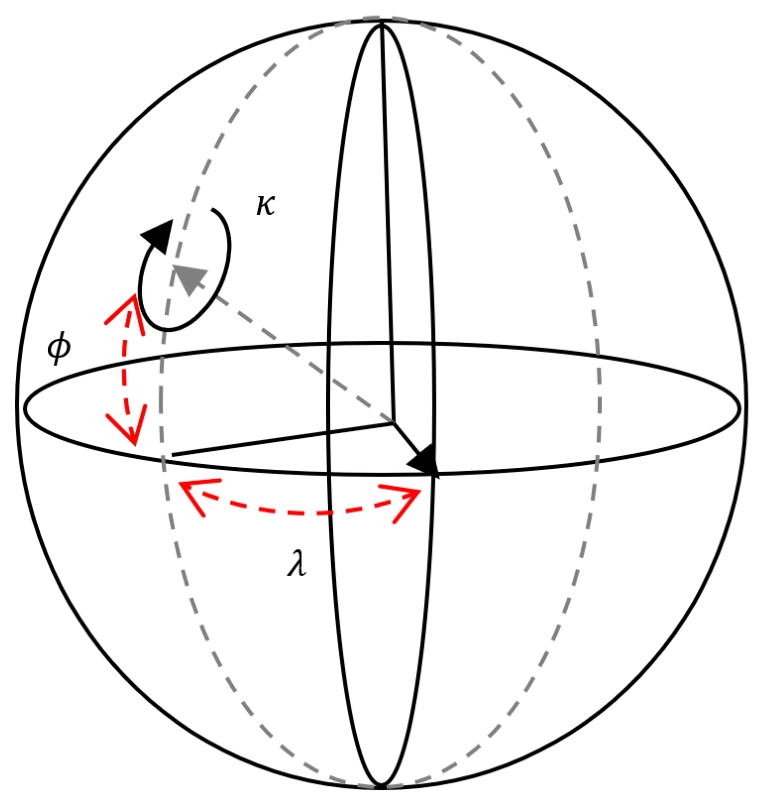
In this work, the aforementioned angular presentation is called “spherical angles”, since it uses spherical coordinates to express any rotation matrix (Figure 2). In the “spherical angles” presentation, all possible rotation matrices are expressed as an angular rotation vector ( ϕ ,   λ ) and a momentum ( κ ). This modification eases the dependence of the collinearity equation on the constraint that should be assumed by quaternions or axis-angle presentation:
ϕ = asin ( x l ) ,   λ = a t a n 2   ( y l , z l )   , κ = w ,
l = x 2 + y 2 + z 2

2.8. Sparse Bundle Block Adjustment

In a classic BBA problem, a system of observational equations is assumed as:
[ f 1 ( l 1 , { X } 1 ) f 2 ( l 2 , { X } 2 ) f m ( l m , { X } m ) ] m × 1 = 0 m × 1 ,
where f i is the ith observational equation, l i is the ith observed variable, and { X } I is the set of unknown variables that are involved in the ith observational equation (constant parameters are hidden here, and bold letters represent vectors). This equation is rewritten in a vector form as:
f m × 1 ( x n × 1 , l m × 1 ) = 0 m × 1
Standard least-squares framework involves an optimization process concerning a cost function that is the sum of squares of the residuals (Equation (13)). The least-squares optimization process results in:
a r g m i n x , l   f . Σ L 1 . f ,
where f is the vector of observational equations (Equation (13)), and Σ L is the covariance matrix of observations. The standard solution to Equation (14) is:
X ^ = [ A T . ( B . P 1 . B T ) 1 . A ] 1 . [ A T . ( B . P 1 . B T ) 1 . W ] ,
where A is the Jacobian matrix with respect to unknowns, B is the Jacobian matrix with respect to observations, P is the weight matrix, W is the residual matrix,   σ 0 2 is the a priori factor variance, Σ L is the covariance matrix of observations, and X ^ is the estimated unknown matrix. The structure of A in (Equation (15)) depends on the order of unknowns. A well-designed ordering helps to simplify A by grouping similar parameters, e.g., a suitable ordering could be arranged such that x = {sensor parameter, camera position and orientations, 3D object points coordinates}.
In most real cases, A requires a considerable amount of RAM. A more efficient solution is to implicitly allocate and fill “ N = A T . ( B . P 1 . B T ) 1 . A , since the N ’s dimension is independent of the number of equations. The former indirect addressing could significantly decrease the amount of RAM required to address Equation (15), especially for cases where a large number of equations exists.
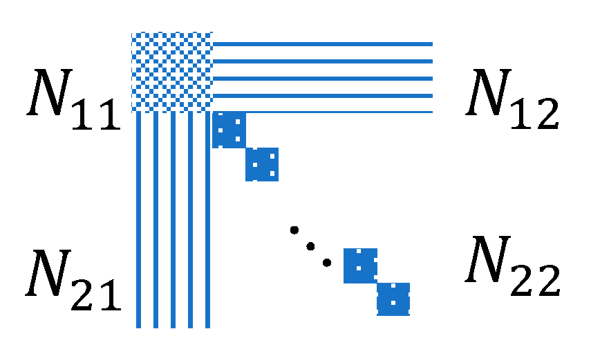
A second improvement is feasible by considering object points as nuisance parameters. This splitting comes in handy when N has a manageable big sub-structure. In this case, by employing the given ordering, one may split N = [ N 11   N 12   N 21   N 22   ] , where N 22 concerns the sub-structure part (Figure 3). In this form, N 22 has “small 3 × 3 sub-matrices” on its main diagonal. N 22 could consequently be allocated and filled in a more efficient way. The advantages of this matrix formation are two-fold: 1—it requires considerably less memory, and 2—it is much faster to invert.

3. Material and Methods

3.1. Datasets

Four datasets (DS1-DS4) were employed, each of which contained an image set, ground control points (GCPs), checkpoints, and GNSS and IMU observations. Two datasets (DS1 and DS4) were considered to investigate the proposed monocular SLAM, and the other datasets (DS2 and DS3) were mainly employed to investigate the sparse BBA parametrization and system calibration.
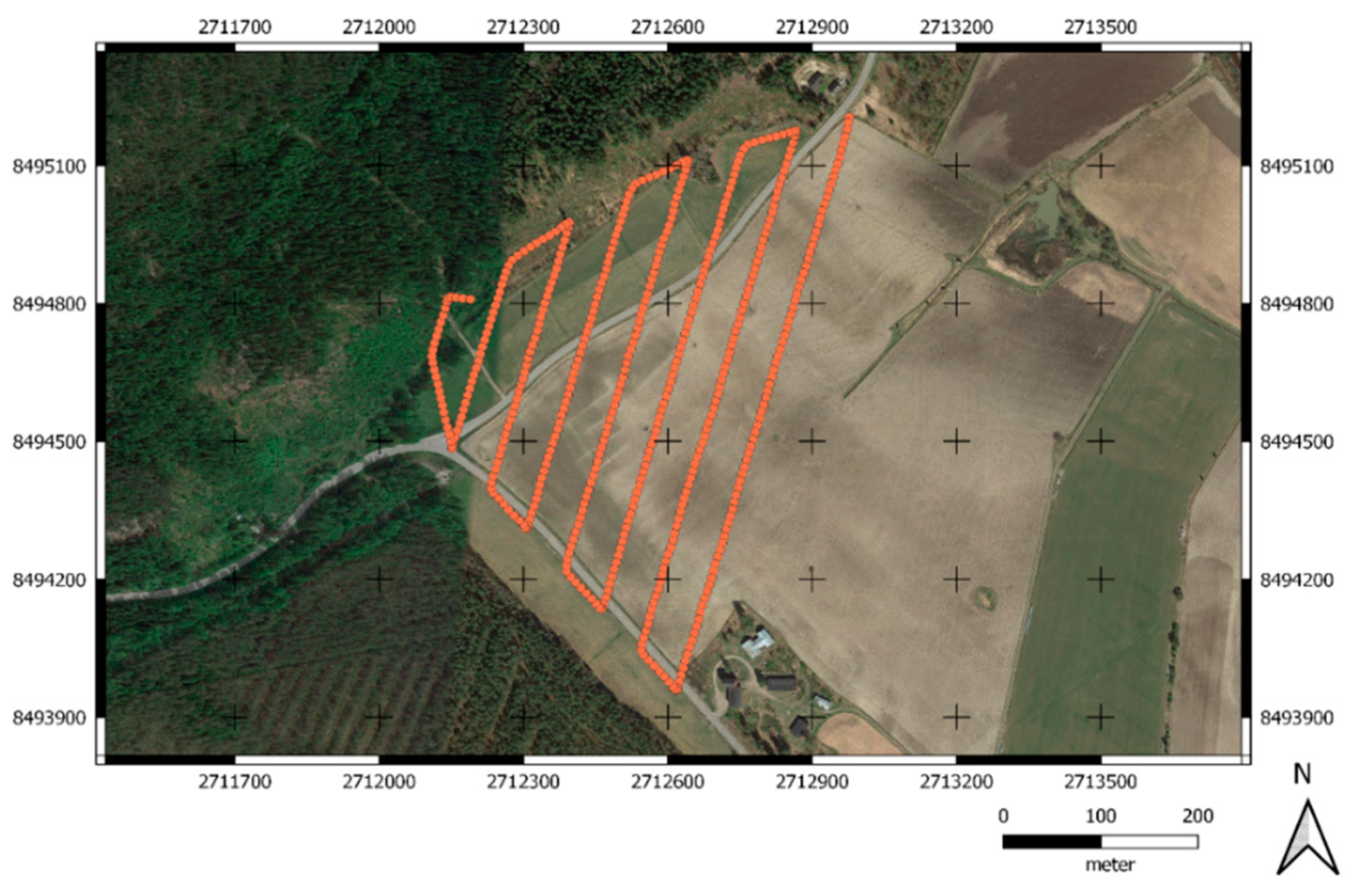
The first dataset (DS1) was captured in July 2017 and it included 246 images of a field and forest area located in the municipality of Vihti in southern Finland (approximately 60°25′ N, 24°22′ E) (Figure 4). The dataset was collected using a Tarot 960 hexacopter attached to a Samsung NX500 camera with a Samsung 16 mm f/2.4 lens. The payload included a Raspberry PI computer, single band GNSS-receiver NVS NV08C-CSM (NVS Navigation Technologies Ltd., Montlingen, Switzerland) and Vectornav VN-200 IMU-receiver (VectorNav Technologies, Dallas, TX, USA). A total of 32 GCPs were distributed uniformly in the field. The GCPs were black-painted plywood boards of size 0.5 m by 0.5 m, with a white painted circle with a diameter of 0.3 m, and they were measured using Trimble R10 RTK DGNSS (Trimble Inc., Sunnyvale, CA, USA) with an accuracy of 3 cm vertically and 4 cm horizontally [49]. The flying height of 140 m resulted in a ground sampling distance (GSD) of 3.2 cm, and forward and side overlaps of 93% and 75%, respectively.
The second and third datasets (DS2 and DS3) were collected in October 2018 in the Sjökulla calibration field of the Finnish Geospatial Research Institute (FGI), located in the municipality of Kirkkonummi in southern Finland (approximately 60°14′ N, 24°22′ E). In the Sjökulla calibration field, a total of 39 reference points were distributed uniformly in the field to be used as GCPs and checkpoints (CPs). In a small part of the calibration field, the reference points were targeted using black and white checkered aluminum square targets of size 0.3 m by 0.3 m, and in the rest of the field, black-painted plywood boards of size 0.5 m by 0.5 m with a white painted circle with a diameter of 0.3 m were installed.
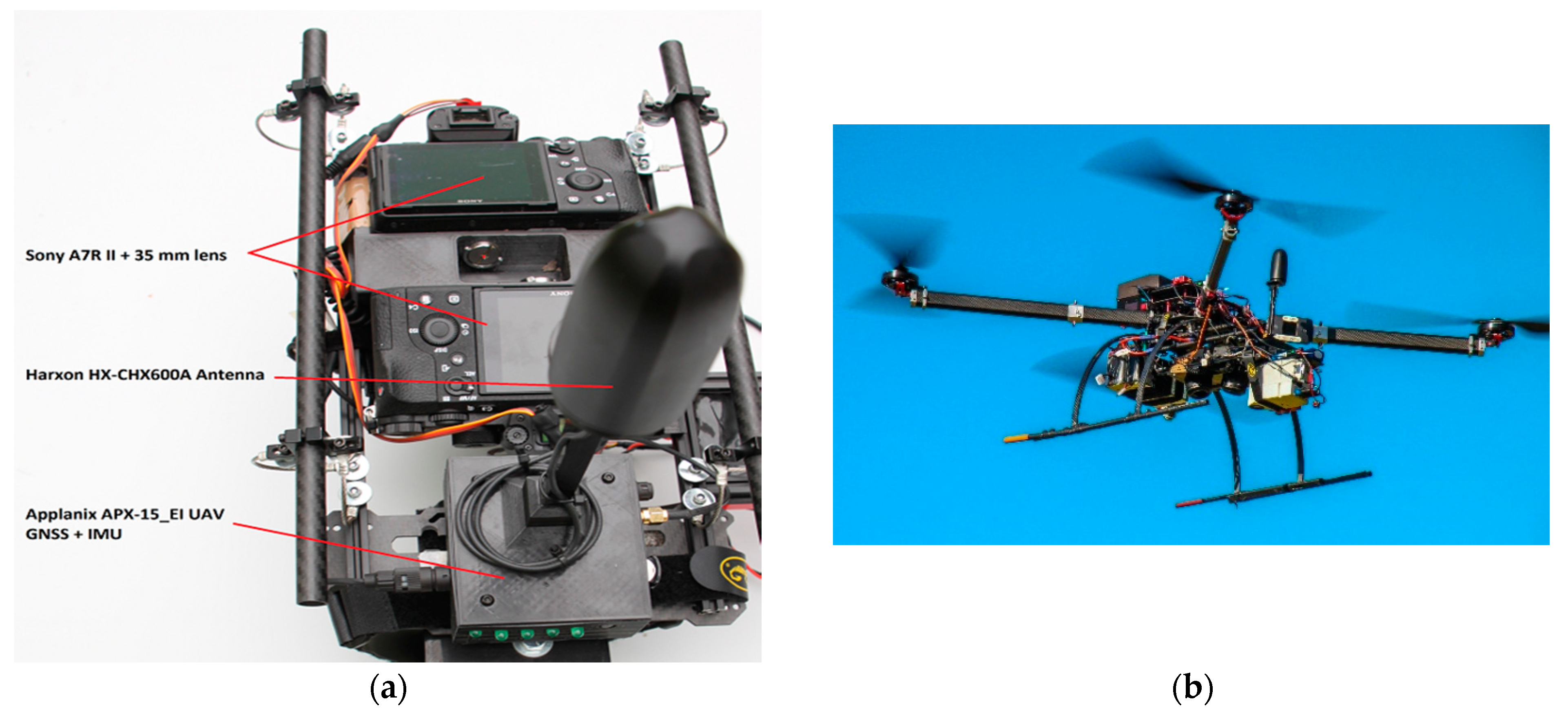
The reference points were measured with the Topcon Hiper HR collecting static measurements of raw observation data at a minimum of 10 min for each point. Furthermore, we calculated static GNSS positions for each reference point using the National Land Survey of Finland (NLS) RINEX service, which offers observation data from FinnRef stations [50], in an open-source RTKlib (RTKlib version 2.4.2, Open-source, Raleigh, NC, USA) rnx2rtkp tool [51]. Topcon Hiper HR’s horizontal accuracy was 3 mm + 0.1 ppm and vertical accuracy was 3.5 mm + 0.4 ppm resulting in a test area with an accuracy within 3.3 mm horizontally and 4.6 mm vertically. Both datasets DS2 and DS3 were captured using two flying heights of 50 m and 25 m resulting in GSDs of 0.64 cm and 0.32 cm. The reason for choosing two flying heights was to strengthen the networks to enable more accurate system calibration. The forward and side overlaps were ~90% and ~80% for these two datasets. The UAV had the Gryphon Dynamics quadcopter frame and it was equipped with a positioning system consisting of Trimble’s APX-15 EI UAV GNSS-Inertial OEM System, comprising APX-20 UAV GNSS-Inertial OEM (multiband GNSS and Internal onboard IMU59) and Harxon HX-CHX600A Antenna (Figure 5). The APX-20 UAV GNSS Inertial OEM was stated by the manufacturer to achieve a postprocessed accuracy of 0.02—0.05 m for positions, 0.025° for roll and pitch and 0.080° for true heading. The drone was carrying two Sony A7R II RGB digital cameras equipped with a Sony FE 35 mm f/2.8 ZA Carl Zeiss Sonnar T* lens (Sony Corporation, Minato, Tokyo, Japan) and 7352 × 5304 pixel CMOS detectors. They were mounted in +15° and −15° oblique angles in the flight direction in a stabilized rack with APX-20 GNSS-Inertial OEM. These cameras are labeled in this work as the “front” and the “back” cameras, and the datasets collected by the cameras were named DS2 and DS3, respectively. The cameras were triggered to capture images in two-second intervals using Sony’s time-lapse software, and APX-20 was used to record the exact time of each camera’s hot shoe output signal. We calculated PPK GNSS solutions and angles for each camera using single base differential GNSS-Inertial processing in Applanix POSPac UAV (Version 8.3). For base station data we downloaded Virtual Reference Station (VRS) from the National Land Survey of Finland (NLS) RINEX service, which offers observation data in Finland from FinnRef stations [50].
The fourth dataset (DS4) was captured in September 2017 in a grass field located in the municipality of Jokioinen in southwest Finland (approximately 60°48′ N, 23°30′ E). The Gryphon Dynamics quadcopter was equipped with a positioning system consisting of an NV08C-CSM L1 GNSS receiver (NVS Navigation Technologies Ltd., Montlingen, Switzerland), a Vectornav VN-200 IMU (VectorNav Technologies, Dallas, TX, USA) and a Raspberry Pi single-board computer (Raspberry Pi Foundation, Cambridge, UK).
The UAV was carrying an RGB digital camera, a Sony A7R (Sony Corporation, Minato, Tokyo, Japan) equipped with a Sony FE 35 mm f/2.8 ZA Carl Zeiss Sonnar T* lens (Sony Corporation, Minato, Tokyo, Japan). The size of raw images was 7360 pixels × 4910 pixels. The camera was triggered to capture images at two-second intervals, and a GNSS receiver was used to record the exact time of each images hot shoe signal output from camera; for each camera PPK GNSS positions were calculated by employing the NLS RINEX service [50], in the RTKlib software rtkpost tool [51]. The flying height of 50 m resulted in a GSD of 0.64 cm and forward and side overlaps of 86 % and 78 %, respectively. GCPs were measured with the Trimble R10 RTK DGNSS.

3.2. Real-Time Computing

A computer equipped with a Core i7 4712HQ processor, 16 GB of RAM, and an NVIDIA GeForce GT 750M 2 GBytes GDDR5 graphical processing unit (GPU) was used to simulate real-time computing of the trajectories and network estimations. The processor had four physical cores and eight logical cores. Our proof-of-concept implementation employed the OpenMP library to parallelize the execution whenever possible.

3.3. Multilevel Matching

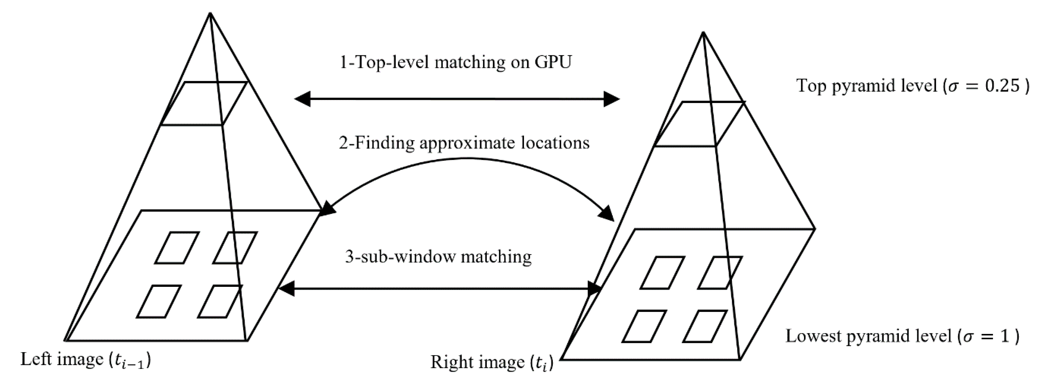
A multilevel matching scheme is a good strategy to improve the computational complexity of a stereo or multi-image matching scheme. For a given pair of images, low pyramid levels with lower resolutions than the original images were initially matched to find approximate locations of small sub windows with higher resolution levels. A quicker matching algorithm was achieved based on three steps: 1—low-resolution image matching, 2—sub-window propagation, and 3—high-resolution sub-window matching. Figure 6 demonstrates the multilevel matching steps that aim to decrease the computational cost of the matching of high-resolution images, while keeping the accuracy at an acceptable level. In this figure, a new image is labeled as “right”, and the last oriented image of the network is labeled as the “left image”.
The image matching operation was initially performed on the top pyramid level ( σ = 0.25 ) for “low-resolution” images under a time limit constraint that was a fraction of a second (Figure 6). The purpose of the low-resolution image matching was to speed up the matching operation, and then selecting only a few sub-regions on the original images was done in order to decrease the extent of the key-point extraction domain. Bicubic sampling was employed on the GPU to shrink the image size and preserve the geometric attributes of the source images. In the matching phase, a cosine measure was employed with a ratio-check mechanism to ensure that the matching algorithm produced high-quality matches. For any given key point on the left image, the algorithm compared the ratio of cosine distances of the first two match candidates on the right image to a threshold. If the ratio was greater than the threshold, the pair would have been selected as a successful match. This comparison helped to find distinctive high-quality matches by ensuring that the final matches were robust. Employing low-resolution matching decreased the execution time to orient the right image to the network. The approximated orientations and position were later enhanced by a local network adjustment. The RANSAC method with a projective transformation kernel was employed to filter most of the remaining outliers.
In the “sub-window” propagation step, the low-level high-resolution rectangular patches (from original image size) of small size (200 × 200 pixels) were considered on the first image. Sub-windows were selected as a few small-size rectangular regions to cover all parts of an image. Then a projective transformation was employed to estimate the corresponding location of all high-resolution sub-windows in the “left image” on the right image. The reason for choosing a projective transformation was due to the near planarity of the object.
In the high-resolution low-level matching step, the low-level rectangles were matched, resulting in a multiple-times decrease in the overall cost of tie point extraction. A high repeatability of tie points was expected when robust (highly distinctive) key-points were detected on the propagated sub-windows. Additional rectangular patches were added to the right image on uncovered places.

3.4. Monocular SLAM

This section provides details and an efficient implementation of the monocular SLAM algorithm that consists of an efficient network creation scheme, multilevel image matching, and local and global adjustment steps. The network creation scheme is called the “modified connect-to-next” approach. The proposed approach employs the multilevel image matching technique described in Section 3.3 as its core component.
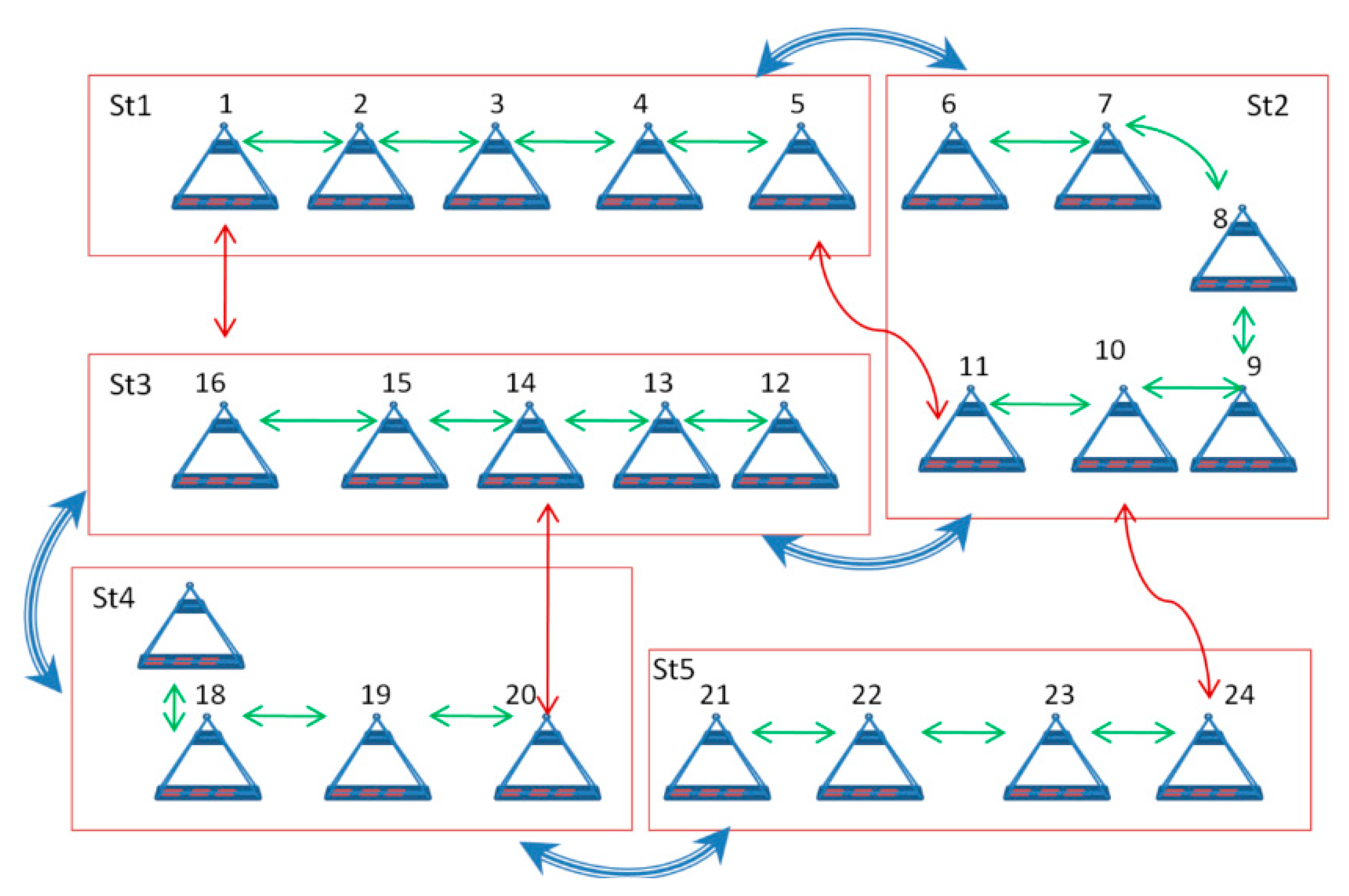
In the modified connect-to-next approach, images are sequentially connected to a global network. Each sequence of 10–20 images are considered as a local network. A new incoming image is added to the global network, and its status (three positions and three orientations) is adjusted by freezing all other parameters of the network (single-image adjustment). Local networks are also individually adjusted and analyzed for quality control and outlier filtering by employing a minimum-constraint sparse BBA. The index number of local networks is marked on images of the global network. Two images of each local network (middle and tail images) are considered for overlap analysis (Figure 7); For each of these two images, a corresponding image with furthest index distance and highest overlap is selected from the previous local network. The overlaps are calculated by assuming that the object is planar; therefore, a plan is fitted to object points, projects of image planes are calculated on the estimated plane, and consequently overlaps are calculated. The multilevel matching is finally performed to add inner-strip tie points. This step is considered to improve the connectivity of the network. When the construction is finished, the global network is optimized by employing a sparse BBA. If the strength of the network allows, a self-calibrating sparse BBA is executed. The output of this algorithm is the adjusted trajectory of the camera and a point cloud in a local or global coordinate system. A local coordinate system is considered when no GNSS and IMU data is provided, however a global coordinate system is employed when GNSS and IMU observations and system calibration parameters are provided. In this case, a system calibration prior to a flight mission is required to robustly estimate lever-arm vector and boresight angles.
Figure 8 demonstrates a comparison between a graph resulting from the “connect-to-all” approach and the “modified connect-to-next” approach. In this figure, the green box contains the new incoming image, and the grey box demonstrates the oriented images. Obviously, fewer links are expected in the modified “connect-to-next” approach.
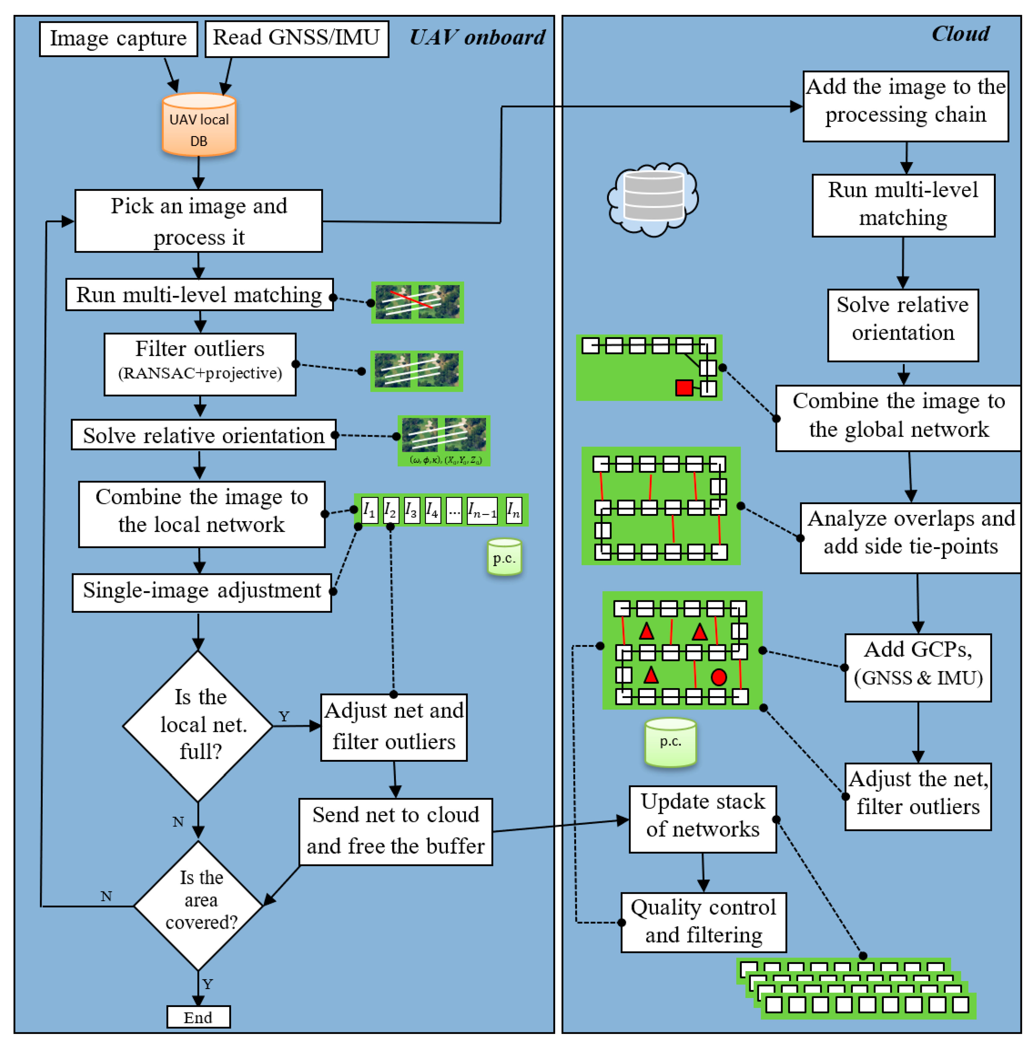
In the implementation step, the UAV onboard computer is considered for fast operations such as image-acquisition, local data storage, low-resolution key-point extraction, and local path estimation close to the capturing moments. A fast data-link between the UAV and a powerful server is required to assign heavier operations to a photogrammetric cloud server. Figure 9 demonstrates a schematic view of mini tasks that were assigned to the UAV’s onboard computer, as well as the cloud (edge-cloud scheme).
Figure 10 demonstrates a top-down workflow of the real-time trajectory estimation algorithm. An “in-UAV” photogrammetric module was considered as the starting point. This approach consequently led to initial structures of networks with a sufficient amount of high-frequency tie points. When the size of the local network is relatively low (< 10 ), the complexity of this algorithm becomes [ N + s × N ], where s = ( α β ) is the sparsity coefficient of a network determined by the number of new connections ( α ) after processing every ( β ) captured image ( α = { 1 : β } ;   α = 0 connect-to-next approach, α = { 1 : 2 } modified connect-to-next approach).
The proposed monocular method was implemented and tested in a simulation empowered by the computer described in Section 3.2 on real datasets (DS1-DS4). The data were fed into the algorithm with a rate similar to real configurations. The multilevel matching algorithm described in Section 3.3 was employed with a SIFT GPU kernel [30] to find a list of high-quality matches for DS1 and DS4. Sensor parameters (IOPs) were kept fixed during the local adjustments of DS1 and DS4 structures due to their geometric instability. Initial structures of DS1 and DS4 were estimated by employing the modified connect-to-next network creation strategy. For these datasets, initially image-based SLAM was performed without GCPs and check-points; in the postprocessing step of DS1, GCPs and checkpoints were included to estimate camera motion and locations of 3D object points in a global frame by employing an over-constraint sparse BBA.
Initial structures of datasets DS2 and DS3 were estimated using the connect-to-all approach (Section 2.3). Spherical angles (Section 2.7) were employed in the sparse BBA (Section 2.8) to estimate the final structure of all of the networks. Sensor parameters were optimized in DS2 and DS3 during postprocessing adjustments since the network structures were strong enough for this purpose. In the final postprocessing adjustments of DS2 and DS3, system calibration parameters (lever-arm vector and boresight angles) were also estimated.
Standard deviation values of observations were employed in the adjustment process to regulate the noise situation and propagate uncertainties to unknowns. The standard deviation value of image-point observations was set as 1 pixel for x and y components. The standard deviation value of GCPs was set as 1.2 cm for X , Y , and Z components. For GNSS readings, a standard deviation value of 2 cm was considered for X , Y , and Z components. For IMU readings, a standard deviation value of 0.002 degrees was considered.

3.5. Performance Assessment

Different performance-assessment methods were employed to evaluate various aspects of the proposed algorithm.
For image matching, the percentage of inliers along with the time factor were considered as the assessment method. SIFT, SURF, and ORB methods were employed in different configurations to assess the accuracy and timing of the proposed image matching approach. The selected matching strategy for SIFT, SURF, and ORB was approximated nearest neighborhood searching [52]. For the multiwindow SIFT a customized matching strategy was considered by employing the cosine distance measure. A second key-point extraction was executed for SURF and ORB to demonstrate the effect of high-quality key-points on the performance of a matching algorithm; it was based on selecting the first 10k high-quality key points. Image-point residuals in pixel units have been employed to assess the quality of intersections and detect outliers in the BBA. The average root-mean-square errors (RMSEs) of all image points were employed to assess the correctness of connecting an image to a network.
Scalar standard deviation values were employed to assess the quality of estimated parameters. These values are estimated as the diagonal element of the covariance matrix of unknowns through error propagation in the standard non-linear least-squares optimization process. Positional uncertainties were expressed as 3D error ellipsoids that were extracted from 3 × 3 covariance sub-matrices of the covariance matrix of unknowns.
Checkpoints were employed to assess the geometric accuracy of the sparse BBA (DS1-DS4). The estimated lever-arm vector and bore-sight angles were employed to transfer the GNSS and IMU readings to the local coordinate systems of images (DS2, DS3). All rotations were converted into spherical angles used in the sparse BBA. These values were finally compared.

4. Results

4.1. Feature-Extraction Methods Comparison

In Table 1, SIFT, SURF, ORB, and multiwindow SIFT key point extraction methods are compared. Overall, SIFT demonstrated the best distribution of match points among all the other methods, however, it required a considerable amount of RAM, especially in comparison to ORB and multiwindow SIFT. SIFT produced an almost similar inlier percentage to that of SURF. ORB, conversely, produced better results than SIFT and SURF. The internal filtering structure in multiwindow SIFT successfully increased the percentage of inliers, while reducing the overall matching time. The distribution of matching point was improved by employing the windows matching.

4.2. Multilevel Matching

By employing the proposed multilevel matching scheme (Section 3.3), the overall cost of image matching decreased from ~60 s to 3.1 s for a stereo pair. On average, the image-based network creation was at the same speed of data capturing which implied a real-time monocular SLAM performance. The frequency of tie points was sufficiently increased by the sub-window propagation scheme that allowed for a robust adjustment of the networks.
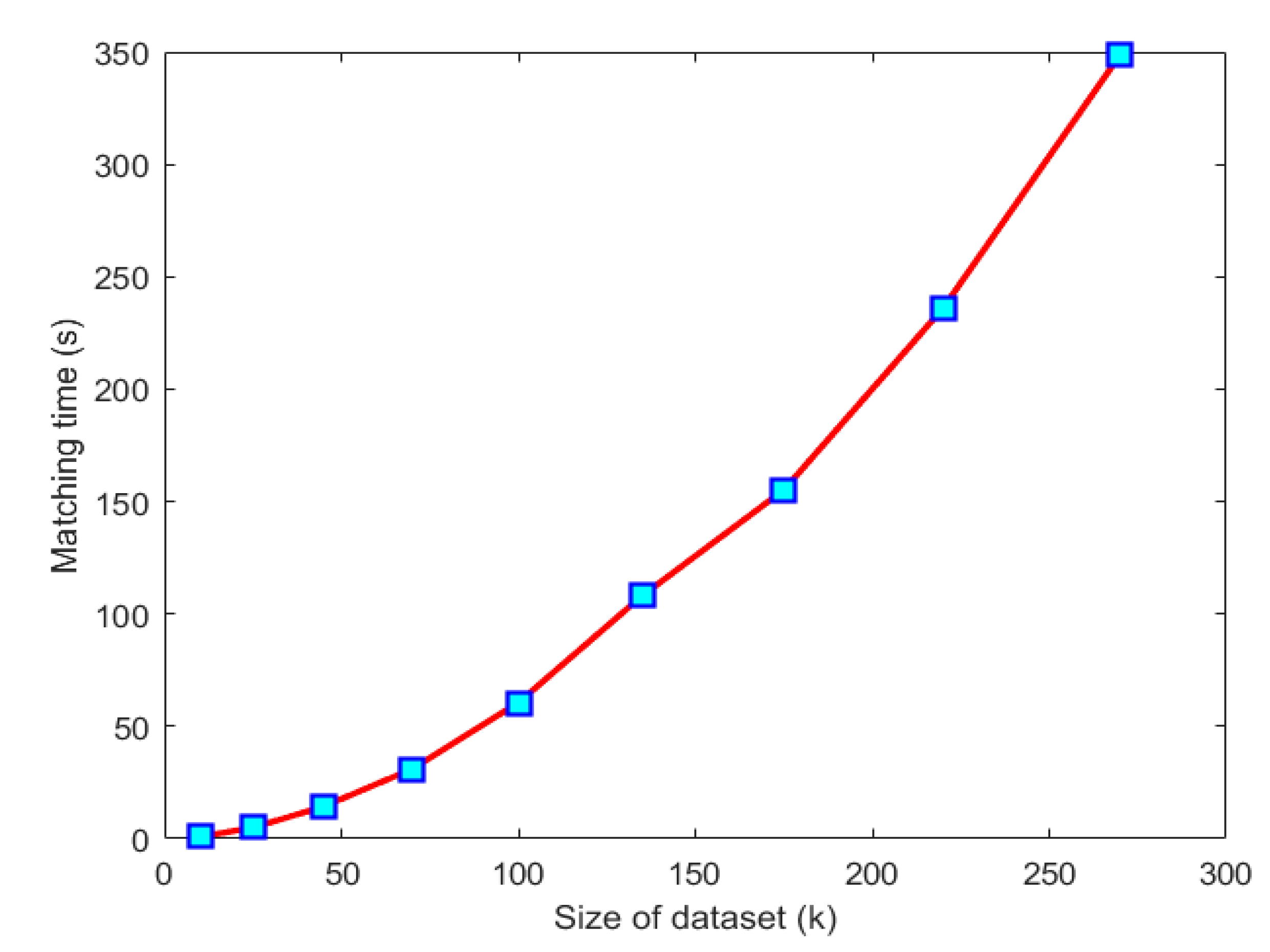
Figure 11 demonstrates the matching time as a function of key-point number. In can be noted that the matching time is superlinear in this figure with respect to the number of key points. This implies that a lower number of key-points are favorable for constructing a real-time matching scheme.
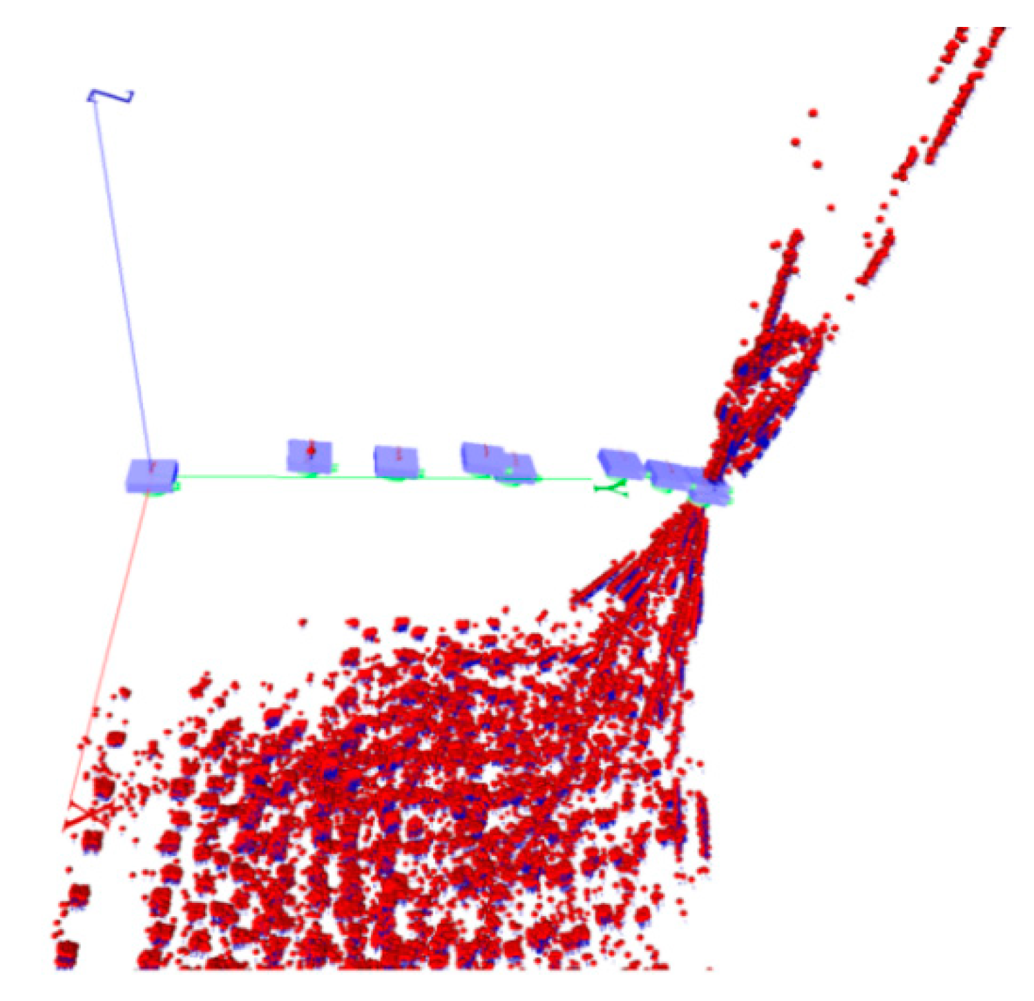
Figure 12 demonstrates a scale issue during connecting a new image to the network. This problem occurred when insufficient common tie points between the network and last pair were found; consequently, the scale parameter between the last pair and the network became unstable. This figure highlights the importance of high-frequency tie points in constructing a network. Since sub-windows were propagated in the process, common tie points were extracted that decreased the possibility of a linkage singularity. The proposed multilevel matching strategy suitably addressed this problem.

4.3. Image-Based SLAM

Figure 13 demonstrates the results of the image-based SLAM for a short trajectory of 10 image pairs from DS1 dataset. Figure 13a shows the estimated UAV trajectory and 3D points. Figure 13b demonstrates accumulation of the trajectory uncertainty along the estimated UAV path with 100× magnification. No GNSS or IMU readings were employed to estimate these paths. A local coordinate system was considered, with the focal point of the first image being the origin of the coordinate system, axis parallel to image plane, and an arbitrary scale (unit base-line). A minimum constraint adjustment was employed by keeping the status of the first image and the furthest distance fixed. As the UAV moved forward, the amount of uncertainty in the predicted image-based trajectory increased; therefore, the essence of side tie points and high-frequency points in strengthening the network structure was highlighted. In Figure 14, a longer path of 40 images from the same dataset is demonstrated. The effect of sub-window matching is visible on locations of 3D object points.
Figure 15 demonstrates the network of DS1 that was created by combining pairs without performing a single-image BBA, which resulted in a deformed path. Figure 15b demonstrates the same network by considering single-image adjustments, which shows a successful example of the proposed approach. Obviously, the adjustment improved the final outcome.
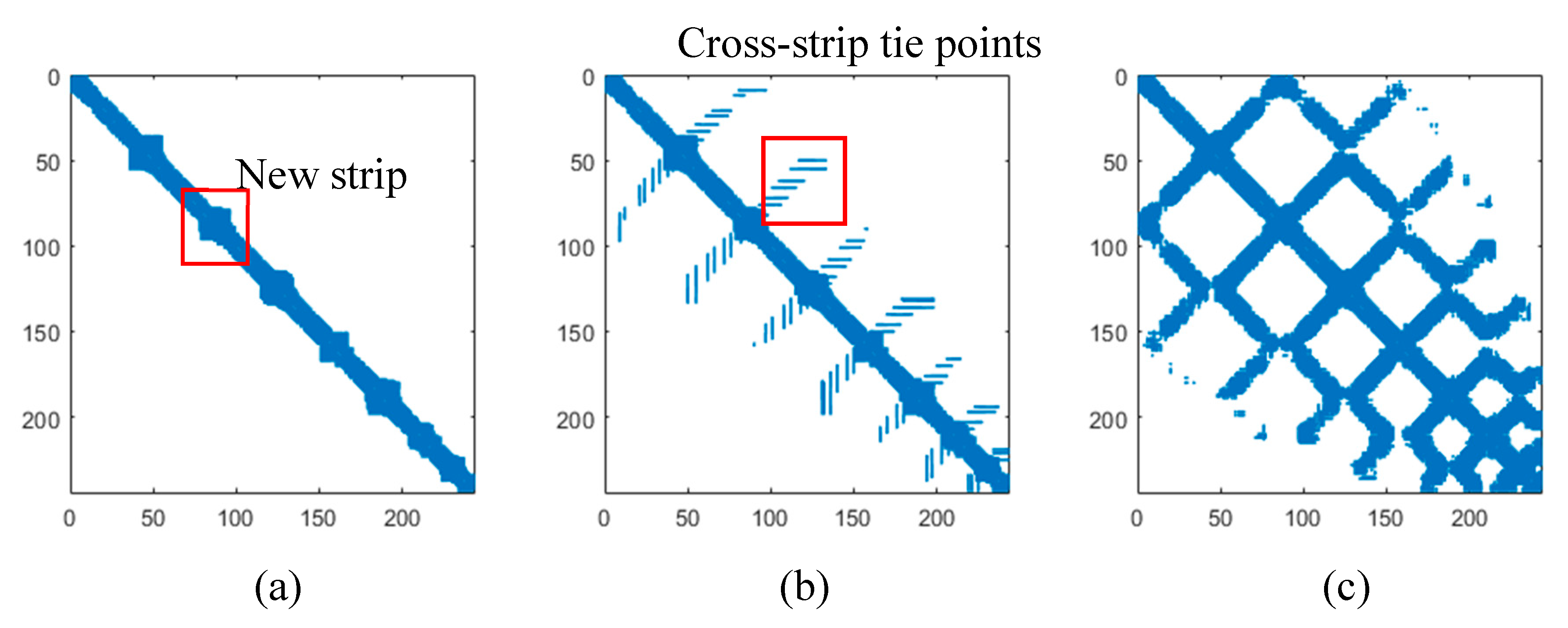
Figure 16 demonstrates the structural matrices of the DS1 network, by employing different network creation strategies. Blue points show the existence of common tie points between two images. In Figure 16a a connect-to-next approach was employed; consequently, the structure of the resulted network was sparse. More links are visible on locations where a new strip starts. For comparison, the connect-to-all approach was employed on this dataset at the maximum computational cost and the result is demonstrated in Figure 16c. The sparse structure improved by applying the proposed overlap analysis by the modified connect-to-next approach, which balanced the time and the computation cost (Figure 16b).

4.4. Postprocessing

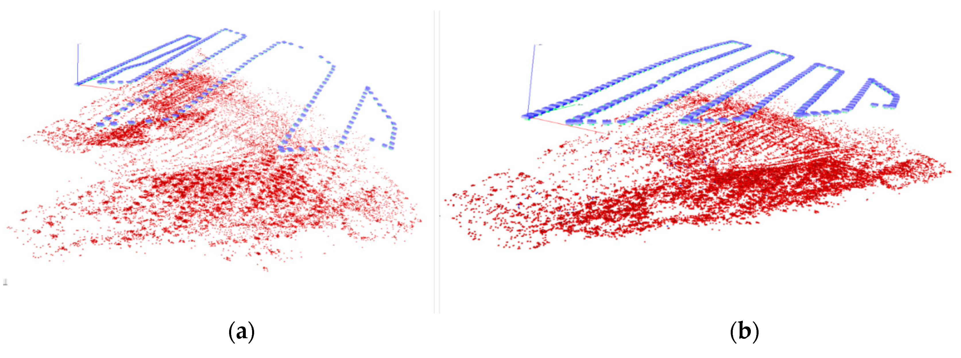
Figure 17a demonstrates the adjusted structure of DS2 after postprocessing. On average, a 0.64 pixel image-point residual with standard deviation of 0.71 pixel was observed for DS1. Average differences of 1.9 cm, −1.1 cm, and 0. 7 cm in the components X, Y, and Z of GNSS readings and the output of BBA were observed for GCPs of DS1. The differences for the GCPs and checkpoints of DS2 are listed in Table 2 and Table 3 respectively. A mean residual of 2.24 cm with RMSE of 1.26 cm was observed for GCPs of DS2. The checkpoints of DS2 presented similar accuracy to the GCPs, with mean residual of 1.32 cm and RMSE of 0.99 cm.
Figure 17b demonstrates the adjusted structure of DS3. On average, a 0.60 pixel image-point residual with standard deviation of 0.71 pixel was observed for DS3, which was similar to DS2. Residuals of GCPs and check points of DS3 are listed in Table 4 and Table 5. A mean residual of 1.4 cm with RMSE of 0.76 cm was observed for GCPs of DS3. The checkpoints of DS3 had higher accuracy than the checkpoints of DS2, with mean residual of 0.9 cm with RMSE 0.52 cm. The higher 3D positional accuracies of DS3 in comparison to DS2 were also visible by comparing their image-point residuals.
Table 6 lists the calibrated values for DS2 and DS3 camera IOPs and system calibration parameters and their standard deviation. On average, a 0.57 pixel image residual with standard deviation of 0.68 pixel was observed for DS2. The estimated standard deviation values of the IOPs between DS2 and DS3 were similar, which was expected. All of the IOPs were observed as meaningful, since the standard deviation values of the IOPs were less than estimated values. Mounting parameters of the cameras with respect to the GNSS and IMU (lever-arm vector and boresight angles) accurately resembled the physical reality of the sensor. The accuracy for the “Front camera” (D2) dataset was also similar (Table 2, Table 3, Table 4 and Table 5). The residuals confirm that the calibration process has been successful.
Figure 17c demonstrates the adjusted structure of DS4. On average, a 1.33 pixel image-point residual with standard deviation of 1.84 pixel was obtained for DS4.
The Euler angular framework was unable to address DS2 and DS3 adjustments, since the gimbal-lock singularity occurred in both cases. The proposed method employed the spherical angles as a successful alternative to address the singularities. Average differences in cameras position were 1.466 cm, 1.423 cm, 1.371 cm and 2.03 cm, 2.01 cm, 1.98 cm in the components X, Y, and Z of GNSS readings and the output of BBA after applying calibrated lever-arm vector and boresight angles for the “Back” (DS3) and “Front”(DS2) camera, respectively.
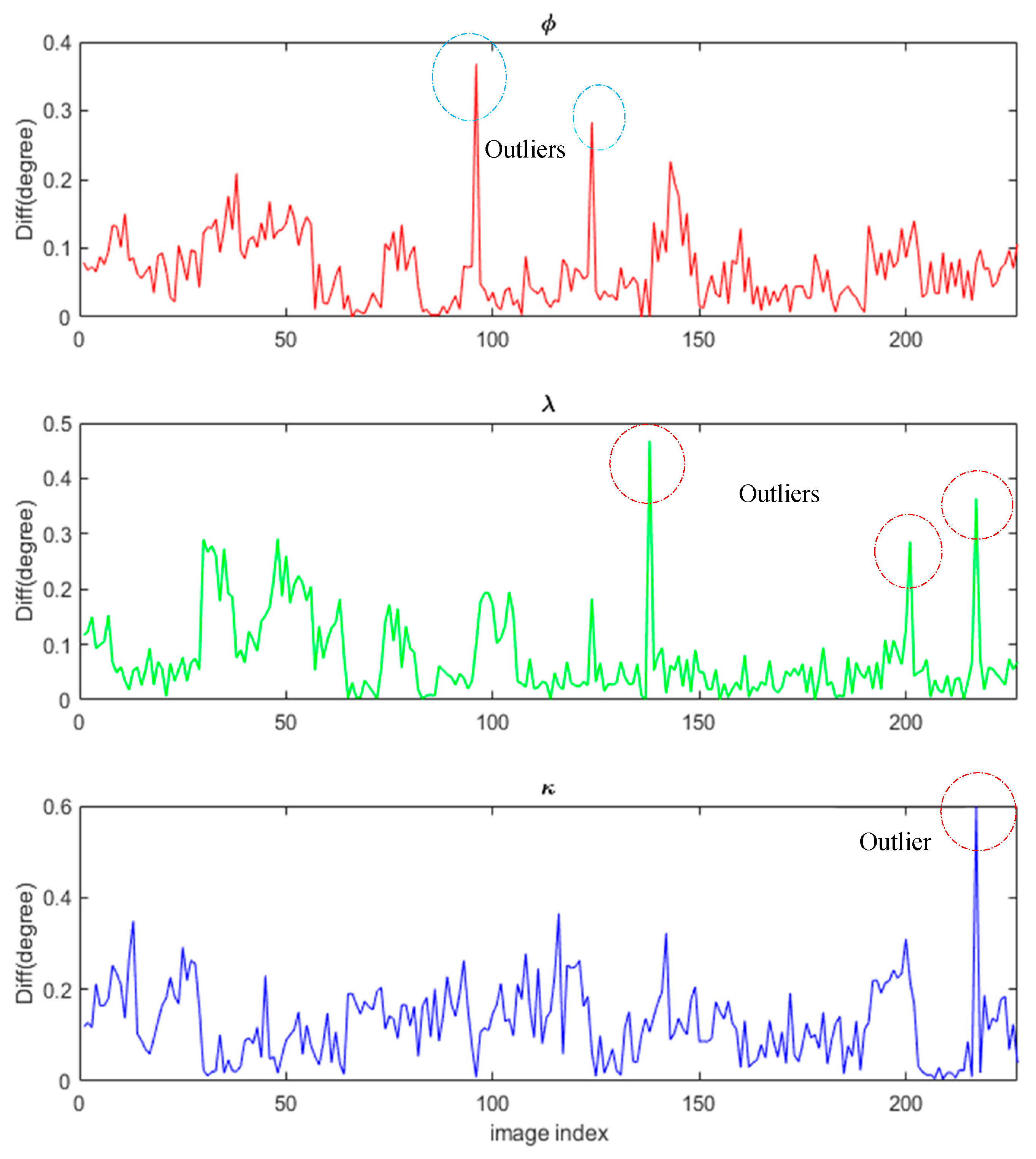
Differences between the IMU observations and adjusted image orientations that were back projected by employing the calibrated boresight angles are demonstrated in Figure 18 for DS2. The observational residuals presented were mostly less than 0.2 degrees, which was the expected difference based on the IMU accuracy (standard deviation value of 0.2 degrees). Some outliers could be seen in this figure which were filtered out before the adjustment step. Those differences were similar between the front and the back camera.

5. Discussion

The modified sequential approach successfully addressed drawbacks of a simple sequential approach by proposing fixes to each of them: to address the first issue, image points were tracked in propagated sub-windows to produce tie points with high frequency in sufficient numbers. The complexity of the modified approach remained [ N ] despite applying this modification. This was the initial goal of the modified sequential approach that was fulfilled; additional edges were consequently added to the structure of the network by employing label propagation. The second issue was addressed by implementing a progressive photogrammetric overlap analysis to effectively find potential connections for a new image; therefore, only a few images of any incoming local network (tail and middle of a sparse pattern) were selected to be analyzed for new possible edges. This ensured adding a minimum number of edges to avoid extra connections. The overlap analysis was enabled by assuming that the object is near planar. This is a limitation of our approach that needs to be further studied and improved for other cases. The third issue was addressed by limiting the matching domain. By this modification, only a few small sub-windows were initially selected in the first image; then a low-resolution image matching a high pyramid-level was employed to find approximate corresponding locations inside a second image; finally, matches between local sub-windows were sought, which were less computationally-demanding because of the small size of the sub windows. The locations of matching windows were finally propagated by employing a projective transformation in order to preserve the high-frequency of image tie points. In the proposed scheme, some light operations were considered to be performed onboard, however, heavier computations such as block optimization were assigned to the cloud computer.
The proposed edge-cloud scheme continues the trend that relies on onboard computing, such as in the case of [20]. The proposed multilevel matching strategy acted faster than methods such as [30,32,35] on matching high-resolution images. The proposed scheme has the flexibility of employing each of the state-of-the-art image-matching methods as its internal matching kernel. The proposed monocular SLAM solution solved the aerial situations that we found difficult to address by the other methods such as [20] and [42]. The proposed angular parametrization addressed the gimbal lock singularity in an efficient way. The error propagation that is addressed here is similar to works such as [53], however, we decomposed positional covariance sub-matrices to produce positional 3D error ellipsoids. This useful presentation significantly helped to find the shortcomings of the monocular SLAM, which were mainly related to efficient image matching and optimal network creation.
Powerful single-board computers are currently available in the market that have comparable or even better performance than the computer system employed in this research. Despite that, the proposed method was implemented and tested in a simulation with a desktop computer, and a powerful single-board computer could be easily employed for a real scenario.
Our future research will aim to improve the shortcomings of the proposed matching strategy, especially when texture information is not adequate for the matching phase. We intend to overcome difficult cases by employing novel artificial intelligence (AI) methods.

6. Conclusions

We proposed a novel monocular SLAM approach and demonstrated its success in the absence of GNSS and IMU observations. The proposed matching strategy was observed as a fast and accurate method for real-time SLAM that was able to perform the matching based on a real-time schedule. The multiscale propagation scheme significantly decreased the computational cost. Sub-window matching was observed as a good strategy to maintain a balance between the algorithm’s complexity and accuracy. This strategy also improved the local structure of the networks, which helped increase the repeatability of the local tie points. The overlap analysis decreased the sizes of positional error ellipses of camera positions by adding side tie points. This step turned out to be important in strengthening the structure of the network. Most of the outliers resulting from the matching phase were successfully detected by the RANSAC module with a projective kernel. Adjustment of local networks was demonstrated as a very useful tool to detect outliers. Accumulation of positional uncertainty of the trajectory estimation was considerably improved by adding side tie points and executing local adjustments in an optimal way that took the timing constraints into account. The postprocessing adjustment was demonstrated to resolve the system calibration when GNSS and IMU observations were available.

Author Contributions

Conceptualization, E.K., R.A.O. and E.H.; Methodology, E.K.; Software, E.K.; Validation, E.K., N.K., and E.H.; Investigation, E.K., and N.K.; Resources, E.H.; Writing—original draft preparation, E.K.; Writing—review and editing, E.K., R.A.O., N.K., and E.H.; Visualization, E.K.; Supervision E.H.; Project administration, E.H.; Funding acquisition, E.H. All authors have read and agreed to the published version of the manuscript.

Funding

This research was financially supported by the Academy of Finland project “Autonomous tree health analyzer based on imaging UAV spectrometry” (Decision number 327861). Open access funding provided by University of Helsinki.

Conflicts of Interest

The authors declare no conflict of interest. The funders had no role in the design of the study; in the collection, analyses, or interpretation of data; in the writing of the manuscript, or in the decision to publish the results.

References

  1. Honkavaara, E.; Saari, H.; Kaivosoja, J.; Pölönen, I.; Hakala, T.; Litkey, P.; Mäkynen, J.; Pesonen, L. Processing and assessment of spectrometric, stereoscopic imagery collected using a lightweight UAV spectral camera for precision agriculture. Remote Sens. 2013, 5, 5006–5039. [Google Scholar] [CrossRef] [Green Version]
  2. Suomalainen, J.; Anders, N.; Iqbal, S.; Roerink, G.; Franke, J.; Wenting, P.; Hünniger, D.; Bartholomeus, H.; Becker, R.; Kooistra, L. A lightweight hyperspectral mapping system and photogrammetric processing chain for unmanned aerial vehicles. Remote Sens. 2014, 6, 11013–11030. [Google Scholar] [CrossRef] [Green Version]
  3. Oliveira, R.A.; Khoramshahi, E.; Suomalainen, J.; Hakala, T.; Viljanen, N.; Honkavaara, E. Real-time and post-processed georeferencing for hyperpspectral drone remote sensing. Int. Arch. Photogramm. Remote Sens. Spat. Inf. Sci. 2018, 42, 789–795. [Google Scholar] [CrossRef] [Green Version]
  4. Hu, Z.; Bai, Z.; Yang, Y.; Zheng, Z.; Bian, K.; Song, L. UAV aided aerial-ground IoT for air quality sensing in smart city: Architecture, technologies, and implementation. IEEE Netw. 2019, 33, 14–22. [Google Scholar] [CrossRef] [Green Version]
  5. Boccardo, P.; Chiabrando, F.; Dutto, F.; Tonolo, F.G.; Lingua, A. UAV deployment exercise for mapping purposes: Evaluation of emergency response applications. Sensors 2015, 15, 15717–15737. [Google Scholar]
  6. Casbeer, D.W.; Beard, R.W.; McLain, T.W.; Li, S.-M.; Mehra, R.K. Forest fire monitoring with multiple small UAVs. In Proceedings of the 2005, American Control Conference, Portland, OR, USA, 8–10 June 2005; pp. 3530–3535. [Google Scholar]
  7. Zhou, G. Near real-time orthorectification and mosaic of small UAV video flow for time-critical event response. IEEE Trans. Geosci. Remote Sens. 2009, 47, 739–747. [Google Scholar] [CrossRef]
  8. Puri, A.; Valavanis, K.; Kontitsis, M. Statistical profile generation for traffic monitoring using real-time UAV based video data. In Proceedings of the 2007 Mediterranean Conference on Control & Automation, Athens, Greece, 27–29 June 2007; pp. 1–6. [Google Scholar]
  9. Aguilar, W.G.; Luna, M.A.; Moya, J.F.; Abad, V.; Parra, H.; Ruiz, H. Pedestrian detection for UAVs using cascade classifiers with meanshift. In Proceedings of the 2017 IEEE 11th International Conference on Semantic Computing (ICSC), San Diego, CA, USA, 30 January 2016–1 Feburary 2017; pp. 509–514. [Google Scholar]
  10. Li, X.; Chuah, M.C.; Bhattacharya, S. Uav assisted smart parking solution. In Proceedings of the 2017 International Conference on Unmanned Aircraft Systems (ICUAS), Miami, FL, USA, 13–16 June 2017; pp. 1006–1013. [Google Scholar]
  11. Ballari, D.; Orellana, D.; Acosta, E.; Espinoza, A.; Morocho, V. UAV monitoring for environmental management in Galapagos Islands. Int. Arch. Photogramm. Remote Sens. Spat. Inf. Sci. 2016, 41. [Google Scholar] [CrossRef] [Green Version]
  12. Giyenko, A.; Cho, Y.I. Intelligent UAV in smart cities using IoT. In Proceedings of the 2016 16th International Conference on Control, Automation and Systems (ICCAS), Gyeongju, Korea, 16–19 October 2016; pp. 207–210. [Google Scholar]
  13. Bendig, J.; Bolten, A.; Bennertz, S.; Broscheit, J.; Eichfuss, S.; Bareth, G. Estimating biomass of barley using crop surface models (CSMs) derived from UAV-based RGB imaging. Remote Sens. 2014, 6, 10395–10412. [Google Scholar] [CrossRef] [Green Version]
  14. Feng, Q.; Liu, J.; Gong, J. UAV remote sensing for urban vegetation mapping using random forest and texture analysis. Remote Sens. 2015, 7, 1074–1094. [Google Scholar] [CrossRef] [Green Version]
  15. Wallace, L.; Lucieer, A.; Watson, C.; Turner, D. Development of a UAV-LiDAR system with application to forest inventory. Remote Sens. 2012, 4, 1519–1543. [Google Scholar] [CrossRef] [Green Version]
  16. Dash, J.P.; Watt, M.S.; Pearse, G.D.; Heaphy, M.; Dungey, H.S. Assessing very high resolution UAV imagery for monitoring forest health during a simulated disease outbreak. ISPRS J. Photogramm. Remote Sens. 2017, 131, 1–14. [Google Scholar] [CrossRef]
  17. Kang, B.-J.; Cho, H.-C. System of Agricultural Land Monitoring Using UAV. J. Korea Acad. Ind. Coop. Soc. 2016, 17, 372–378. [Google Scholar]
  18. Lottes, P.; Khanna, R.; Pfeifer, J.; Siegwart, R.; Stachniss, C. UAV-based crop and weed classification for smart farming. In Proceedings of the 2017 IEEE International Conference on Robotics and Automation (ICRA), Singapore, 29 May–3 June 2017; pp. 3024–3031. [Google Scholar]
  19. Ribeiro, L.R.; Oliveira, N.M.F. UAV autopilot controllers test platform using Matlab/Simulink and X-Plane. In Proceedings of the 2010 IEEE Frontiers in Education Conference (FIE), Arlington, VA, USA, 27–30 October 2010; p. S2H-1. [Google Scholar]
  20. Caballero, F.L.; Merino, L.; Ferruz, J.; Ollero, A. Vision-based odometry and SLAM for medium and high altitude flying UAVs. J. Intell. Robot. Syst. 2009, 54, 137–161. [Google Scholar] [CrossRef]
  21. Li, B.; Fei, Z.; Zhang, Y. UAV communications for 5G and beyond: Recent advances and future trends. IEEE Internet Things J. 2018, 6, 2241–2263. [Google Scholar] [CrossRef] [Green Version]
  22. Luo, C.; Nightingale, J.; Asemota, E.; Grecos, C. A UAV-cloud system for disaster sensing applications. In Proceedings of the 2015 IEEE 81st Vehicular Technology Conference (VTC Spring), Glasgow, Scotland, 11–14 May 2015; pp. 1–5. [Google Scholar]
  23. Mahmoud, S.Y.M.; Mohamed, N. Toward a cloud platform for UAV resources and services. In Proceedings of the 2015 IEEE Fourth Symposium on Network Cloud Computing and Applications (NCCA), Munich, Germany, 11–12 June 2015; pp. 23–30. [Google Scholar]
  24. Gruen, A.; Huang, T.S. Calibration and Orientation of Cameras in Computer Vision; Springer Science & Business Media: Heidelberg/Berlin, Germany, 2013; Volume 34. [Google Scholar]
  25. Hartley, R.I. In defence of the 8-point algorithm. In Proceedings of the IEEE International Conference on Computer Vision, Cambridge, MA, USA, 20–23 June 1995; pp. 1064–1070. [Google Scholar]
  26. Nistér, D. An efficient solution to the five-point relative pose problem. IEEE Trans. Pattern Anal. Mach. Intell. 2004, 26, 756–770. [Google Scholar] [CrossRef]
  27. Cramer, M.; Stallmann, D.; Haala, N. Direct Georeferencing Using GPS/Inertial Exterior Orientations for Photogrammetric Applications. Int. Arch. Photogramm. Remote Sens. 2000, 33, 198–205. [Google Scholar]
  28. Lowe, D.G. Distinctive image features from scale-invariant keypoints. Int. J. Comput. Vis. 2004, 60, 91–110. [Google Scholar] [CrossRef]
  29. Ke, Y.; Sukthankar, R. PCA-SIFT: A more distinctive representation for local image descriptors. In Proceedings of the 2004 IEEE Computer Society Conference on Computer Vision and Pattern Recognition, Washington, DC, USA, 27 June–2 July 2004; Volume 2, p. II-II. [Google Scholar]
  30. Wu, C. A GPU Implementation of Scale Invariant Feature Transform (SIFT). 2007. Available online: https://github.com/pitzer/SiftGPU (accessed on 28 September 2020).
  31. Morel, J.-M.; Yu, G. ASIFT: A new framework for fully affine invariant image comparison. SIAM J. Imaging Sci. 2009, 2, 438–469. [Google Scholar] [CrossRef]
  32. Bay, H.; Tuytelaars, T.; van Gool, L. Surf: Speeded up robust features. In Proceedings of the European Conference on Computer Vision, Graz, Austria, 7–13 May 2006; pp. 404–417. [Google Scholar]
  33. Rosten, E.; Drummond, T. Machine learning for high-speed corner detection. In Proceedings of the European Conference on Computer Vision, Graz, Austria, 7–13 May 2006; pp. 430–443. [Google Scholar]
  34. Calonder, M.; Lepetit, V.; Strecha, C.; Fua, P. Brief: Binary robust independent elementary features. In Proceedings of the European Conference on Computer Vision, Heraklion, Greece, 5–11 September 2010; pp. 778–792. [Google Scholar]
  35. Rublee, E.; Rabaud, V.; Konolige, K.; Bradski, G. ORB: An efficient alternative to SIFT or SURF. In Proceedings of the 2011 International Conference on Computer Vision, Barcelona, Spain, 6–13 November 2011; pp. 2564–2571. [Google Scholar]
  36. Juan, L.; Gwon, L. A comparison of sift, pca-sift and surf. Int. J. Signal Process. Image Process. Pattern Recognit. 2007, 8, 169–176. [Google Scholar]
  37. Karami, E.; Prasad, S.; Shehata, M. Image Matching Using SIFT, SURF, BRIEF and ORB: Performance Comparison for Distorted Images. Available online: https://arxiv.org/ftp/arxiv/papers/1710/1710.02726.pdf (accessed on 28 September 2020).
  38. Wu, Y.; Tang, F.; Li, H. Image-based camera localization: An overview. Vis. Comput. Ind. Biomed. Art 2018, 1, 1–13. [Google Scholar] [CrossRef] [Green Version]
  39. Williams, B.; Cummins, M.; Neira, J.; Newman, P.; Reid, I.; Tardós, J. An image-to-map loop closing method for monocular SLAM. In Proceedings of the 2008 IEEE/RSJ International Conference on Intelligent Robots and Systems, Nice, France, 22–26 September 2008; pp. 2053–2059. [Google Scholar]
  40. Forstner, W.; Steffen, R. On visual real time mapping for Unmanned Aerial Vehicles. In Proceedings of the 21st Congress of the International Society for Photogrammetry and Remote Sensing (ISPRS), Beijing, China, 3–11 July 2008. [Google Scholar]
  41. Gálvez-López, D.; Tardos, J.D. Bags of binary words for fast place recognition in image sequences. IEEE Trans. Robot. 2012, 28, 1188–1197. [Google Scholar] [CrossRef]
  42. Mur-Artal, R.; Montiel, J.M.M.; Tardos, J.D. ORB-SLAM: A versatile and accurate monocular SLAM system. IEEE Trans. Robot. 2015, 31, 1147–1163. [Google Scholar] [CrossRef] [Green Version]
  43. Fink, G.; Franke, M.; Lynch, A.F.; Röbenack, K.; Godbolt, B. Visual inertial SLAM: Application to unmanned aerial vehicles. IFAC-Pap. 2017, 50, 1965–1970. [Google Scholar] [CrossRef]
  44. Jiang, S.; Jiang, W. Efficient sfm for oblique uav images: From match pair selection to geometrical verification. Remote Sens. 2018, 10, 1246. [Google Scholar] [CrossRef] [Green Version]
  45. Chen, X.; Hu, W.; Zhang, L.; Shi, Z.; Li, M. Integration of low-cost gnss and monocular cameras for simultaneous localization and mapping. Sensors 2018, 18, 2193. [Google Scholar] [CrossRef] [PubMed] [Green Version]
  46. Mikhail, E.M.; Bethel, J.S.; McGlone, J.C. Introduction to Modern Photogrammetry; John Wiley & Sons, Inc.: New York, NY, USA, 2001; Volume 19. [Google Scholar]
  47. Caccavale, F.; Natale, C.; Siciliano, B.; Villani, L. Six-dof impedance control based on angle/axis representations. IEEE Trans. Robot. Autom. 1999, 15, 289–300. [Google Scholar] [CrossRef]
  48. Cheng, P.L. A spherical rotation coordinate system for the description of three-dimensional joint rotations. Ann. Biomed. Eng. 2000, 28, 1381–1392. [Google Scholar] [CrossRef]
  49. Harwin, S.; Lucieer, A. Assessing the accuracy of georeferenced point clouds produced via multi-view stereopsis from unmanned aerial vehicle (UAV) imagery. Remote Sens. 2012, 4, 1573–1599. [Google Scholar] [CrossRef] [Green Version]
  50. National Land Survey of Finland, “Finnref GNSS RINEX Service”. Available online: https://www.maanmittauslaitos.fi/en/maps-and-spatial-data/positioning-services/rinex-palvelu (accessed on 28 September 2020).
  51. Takasu, T. RTKlib: An Open-source Program Package for GNSS Positioning. Tech. Rep. 2013. Available online: http://www.rtklib.com/ (accessed on 28 September 2020).
  52. Muja, M.; Lowe, D.G. Fast approximate nearest neighbors with automatic algorithm configuration. VISAPP 1 2009, 2, 331–340. [Google Scholar]
  53. Engel, J.; Schöps, T.; Cremers, D. LSD-SLAM: Large-scale direct monocular SLAM. In Proceedings of the European Conference on Computer Vision, Zurich, Switzerland, 6–12 September 2014; pp. 834–849. [Google Scholar]
Figure 1. The triplet of (roll, pitch, heading) for a hypothesized airplane type object.
Remotesensing 12 03185 g001
Figure 2. Spherical angles presentation.
Remotesensing 12 03185 g002
Figure 3. Structure of the N matrix with a suitable ordering of unknowns.
Remotesensing 12 03185 g003
Figure 4. Extent of the test area (DS1). Image locations are overlaid as orange dots.
Remotesensing 12 03185 g004
Figure 5. (a) Different components used in the unmanned aerial vehicle (UAV) (b) and an image of the UAV flying in the air.
Remotesensing 12 03185 g005
Figure 6. Schematic view of the multilevel image matching strategy. Sub-windows are plotted as rectangles on original image scales. High-level pyramids are plotted for scale 0.25.
Remotesensing 12 03185 g006
Figure 7. Schematic example of the modified connect-to-next approach. The green double-headed arrow shows connections to a neighbor image. The red double-headed arrow shows connections between local networks.
Remotesensing 12 03185 g007
Figure 8. Schematic view of connect-to-all graph versus the modified connect-to-next. Arrows are connections between images. Gray boxes contain networks of a few images. The green boxes contain new incoming images.
Remotesensing 12 03185 g008
Figure 9. Schematic view of the real-time aerial simultaneous localization and mapping (SLAM).
Remotesensing 12 03185 g009
Figure 10. Algorithm of the proposed image-based simultaneous localization and mapping approach.
Remotesensing 12 03185 g010
Figure 11. Feature matching time with respect to the number of key-points (k).
Remotesensing 12 03185 g011
Figure 12. A failed local network of nine images because of a connection to an unhandled zero base-line pair (DS1).
Remotesensing 12 03185 g012
Figure 13. (a) A successful local network of 10 pairs of images. (b) The corresponding error ellipses with a 100× magnification for better visibility (DS1, “1-11”, minimum-constraint bundle block adjustment (BBA) with fixed sensor).
Remotesensing 12 03185 g013
Figure 14. (a) A successful local network of 40 images. (b) The accumulation of uncertainties along the path with a 100× magnification for better visualization (DS1, “1-40”, minimum-constraint BBA with fixed sensor).
Remotesensing 12 03185 g014
Figure 15. DS1, 245 aerial images. (a) Network structure by simple combination of image pairs; (b) the same network with single-image adjustment (fixed-sensor minimum-constraint sparse BBA).
Remotesensing 12 03185 g015
Figure 16. Structures of DS1 with different network creation strategies: (a) Connect-to-next approach, (b) modified connect-to-next approach with edge overlap analysis, (c) connect-to-all approach.
Remotesensing 12 03185 g016
Figure 17. The optimized network structure of (a) DS2, (b) DS3, and (c) DS4.
Remotesensing 12 03185 g017
Figure 18. Difference between inertial measurement unit (IMU) values, and output of BBA after applying calibrated boresight angles for the back camera (DS3).
Remotesensing 12 03185 g018
Table 1. A comparison between different key-point and descriptor extraction methods for matching two aerial images. Inlier detection (ratio test [<0.8]) and reprojection error (<2 pixels).
NameDatasetImage Size
(MPix)
Key-Point
Time (s)
Matching
Time (s)
Overall Time (s)Memory (MB)Number of Key PointsNumber of InliersInlier %
SIFTDS33516.139.055.19700175k37k21.5%
DS1241149609500215k28k13.3%
SURFDS335114556440204k39k19.4%
DS124125365440221k34k15.6%
DS3350.91.22.138010k4.1k41.1%
ORBDS1241.2200.7201.9390200k55k27.8%
DS1241.00.91.938010k3.7k37.8%
DS3351.4212213.4391200k83k41.7%
* Multilevel match with SIFT kernel
DS1240.0310.14462324k3k92%
Table 2. List of the ground control points (GCP) for the front camera (DS2).
Point NameNo. RaysResidualUnitResidual VectorUnit
25113.1cm(−1.2, −2.0, −2.0)cm
27104.4cm(−2.0, 2.6, −3.0)cm
29100.9cm(0.3, 0.6, −0.6)cm
31110.8cm(−0.2, 0.2, −0.8)cm
32161.8cm(−1.0, 0.1, −1.5)cm
33121.9cm(−0.8, −0.5, 1.6)cm
34134.0cm(0.1, 0.4, −4.0)cm
36101.9cm(1.0, −1.1, −1.2)cm
37121.6cm(1.0, 0.4, −1.2)cm
38110.6cm(−0.2, 0.2, 0.5)cm
40103.6cm(2.2, −1.1, −2.6)cm
41112.2cm(1.5, 0.9, −1.3)cm
Residual mean: 2.24 (cm), RMSE: 1.26 (cm)
Table 3. List of the checkpoints for the front camera (DS2).
Point NameNo. RaysResidualUnitResidual VectorUnit
990.1cm(−0.1, −0.1, −0.0)cm
30140.9cm(−0.3, −0.1, −0.9)cm
35112.4cm(0.5, −0.9, −2.2)cm
39101.8cm(0.6, −0.4, −1.7)Cm
Residual mean: 1.32 (cm), RMSE: 0.99 (cm)
Table 4. List of the ground control points (GCP) for the back camera (DS3).
Point NameNo. RaysResidualUnitRes. VectorUnit
25102.6cm(−0.8, −2.4,−0.6)cm
27171.6cm(−0.5, 1.3, −0.7)cm
29100.6cm(0.4, 0.4, −0.1)cm
31110.6cm(−0.3, 0.3, −0.4)cm
32101.2cm(−1.1, 0.1, −0.5)cm
33111.7cm(−0.9, −0.6, −1.2)cm
34101.6cm(−0.6, 0.3, −1.5)cm
36101.4cm(0.0, −0.4, 1.3)cm
37101.0cm(0.2, 0.2, 1.0)cm
38101.1cm(0.3, 0.6, −0.8)cm
40100.5cm(0.4, −0.3, 0.1)cm
41102.9cm(1.8, 1.0, −2.1)cm
Residual mean: 1.4 (cm),RMSE: 0.76 (cm)
Table 5. List of the checkpoints for the back camera (DS3).
Point NameNo. RaysResidualUnitResidual VectorUnit
9101.0cm(0.2, −0.4, 0.9)cm
30100.5cm(−0.2, 0.1, 0.4)cm
35101.6cm(0.2, −0.5, −1.5)cm
39100.5cm(−0.3, −0.3, −0.3)cm
Sample mean: 0.9 (cm), RMSE: 0.52 (cm)
Table 6. Calibrated interior orientation parameters estimated by the proposed method for the front and back cameras of DS2 and DS3.
NoParam. NameUnitFront (DS2)Back (DS3)
ValueStd.ValueStd.
1Principal Distance px.8006.80.207995.160.39
2Principal Distancemm.36.249e−436.189e−4
3Principal Point x dir.px.4002.70.113986.790.13
4Principal Point y dir.px.2623.40.142604.410.21
5K1N/A−0.03957e−5−0.045837e−5
6K2N/A0.1695704e−40.1854364e−4
7K3N/A0.1371389e−40.089509e−4
8P1N/A0.001044e−5−5e−46e−6
9P2N/A−4e-43e−6−0.00173e−6
10Scale factorN/A−1e-44e−51e−45e−6
11Shear factorN/A7e-62e−6−1e−42e−6
12Pixel size µ m 4.526N/A4.526N/A
13Lever-arm ( ω l ) −105.120.01−75.280.03
14Lever-arm ( ϕ l ) −1.762e−3−1.390.01
15Lever-arm ( κ l ) −1.740.01179.100.04
16Lever-arm ( X 0 b ) cm−0.070.043.840.09
17Lever-arm ( Y 0 b ) cm−3.730.07−14.550.20
18Lever-arm ( Z 0 b ) cm−15.790.04−9.590.09