1. Introduction
Synthetic aperture radar (SAR) has been widely used in military and civil fields because of all-weather and all-day capabilities, as well as its high resolution. The multiple-input multiple-output (MIMO) system was first used in communication engineering to solve the multi-path effect [
1]. Subsequently, this radar system with multiple antennas, called MIMO radar, has gained popularity in the radar field [
2,
3,
4]. The MIMO concept is also highly attractive for SAR systems, as a MIMO SAR system can obtain more equivalent channels than a traditional SAR system; this provides a promising method for solving the contradictions between high resolution, wide swath, and multidimensional challenges [
4,
5,
6]. Assuming that a MIMO SAR system has
M transmitting waveforms and
N receiving channels, then we can obtain at most M*N equivalent receiving channels. Currently, many airborne MIMO SAR systems have been launched, including the PAMIR system in Germany [
7,
8], RAMSES system in France [
9], and CSIR system in South Africa [
10]. The institute of electronics of the Chinese Academy of Sciences conducted flight tests on its own airborne simultaneous MIMO SAR system in 2016 and achieved useful results [
11].
The design of emitting waveforms is a difficult step in MIMO SAR systems. Initially, scholars attempted to modify the traditional communication coding signal for application to the orthogonal waveform design of MIMO SAR. However, this signal form has a high sidelobe level after pulse compression, resulting in image quality degradation [
12]. In 2003, J. Mittermayer and J.M. Martinez discussed the application of Chirp signals with positive and negative frequency modulation in the orthogonal waveform design of MIMO SAR and found that the mismatch of signal energy was spread throughout the image, resulting in a high image noise [
12,
13]. In 2007, J. Kim of the German Space Agency proposed a space-time coding scheme for MIMO SAR imaging. To ensure the orthogonality of signals, this method strictly requires the time-invariant characteristics of a radar channel; otherwise, it will greatly weaken the waveform separation performance. However, this method did introduce the idea of one-dimensional coding for the first time [
5]. G. Krieger of the German Space Agency proposed the concept of multidimensional waveform coding (MWE) in 2008 [
14], which increased the utilization rate of the system and achieved multidimensional observations.
The multidimensional waveform encoding (MWE) technique on transmitting can play an important role in a MIMO SAR system. A transmitting signal can be freely coded in the time domain, frequency domain, space domain, and so on, which may greatly enhance its flexibility and the operation ability in multiple modes of a radar system [
14]. In this mode, the number of multi-phase centers and baseline length are increased, and the waveforms can be distinguished by combining two-dimensional array antenna and digital beamforming (DBF) in elevation, which can greatly improve the imaging capability. In the theoretical framework of MWE, Krieger generalized the short-term shift-orthogonal (STSO) and orthogonal frequency-division modulation chirp (OFDM Chirp) waveforms [
6] and demonstrated their equivalence and consistency in a waveform separation through DBF at the receiving end [
6]. In 2013, J. Kim proposed a novel waveform scheme of a spaceborne MIMO SAR system based on the OFDM chirp signals, and the modulation and demodulation processes of OFDM Chirp signals and signal processing flow were given [
15].
A MIMO SAR system using the MWE technique greatly promotes the diversification of radar functions [
16,
17,
18], for example, it can be applied to a polarized SAR system. Modern radar must determine where a target is, as well as what kind of target it is, i.e., the radar target recognition problem. This problem requires radar to be capable of obtaining the size, shape, attitude, electromagnetic parameters, and surface roughness of the target, and other information [
19]. The conventional single channel SAR can only obtain the target scattering characteristics of the ground scene under a specific polarization transceiver combination, and the information that can be obtained is highly limited. At present, a common method to ensure full polarization in a SAR system is to transmit the waveforms in different polarizations at continuous pulse repetition intervals (PRIs), but this method cannot realize polarization simultaneously. Rommel et al., of DLR (German Aerospace Center) proposed a MIMO SAR system that transmits orthogonal waveforms in different polarizations and can obtain all four parameters of the scattering matrix simultaneously [
20].
DBF on a receiver is a powerful approach for waveform separation and can provide the possibility of MIMO SAR realization [
4,
5,
6,
13,
18,
21,
22,
23]. The receiver antenna is divided into several sub-apertures, and the echoes received by every sub-aperture are weighted differently to form many narrow beams. The DBF technique can be used in both the azimuth and elevation directions to balance the antenna size [
18]. After DBF processing, the mixed echoes are separated into independent signals, and then the conventional SAR imaging method can be performed. Meanwhile, many advanced methods of waveform separation have emerged in recent years. Wang et al., proposed a novel waveform separation scheme based on echo compression. Specifically, apart from simultaneously transmissions, the transmitters are required to radiate alone several times in a synthetic aperture to acquire their private inner-aperture channels, then the energy of each waveforms can be concentrated by the matched-filtering the mixed echoes with the sensed echoes [
24]. Ma et al., proposed a periodic correlation method based on STSO codes, which can separate the mixed signals of MIMO SAR system and overcome the conflict between azimuth resolution and swath width [
25].
Currently, the traditional planar phased array antenna is used in most SAR systems, but it has the following weaknesses: a large volume and mass, a low efficiency, and a high cost [
26,
27]. Conversely, the reflector antenna is better in these aspects. However, the applications of the reflector antenna in SAR system are not as mature as those using a planar antenna. However, owing to the considerable differences in their modes of operation, the geometric model and signal model based on a reflector antenna are different from those based on a planar antenna [
28,
29]. Huber et al., proposed a digital beamforming in 3-D time-wavenumber space, expanded the temporal domain to the time-frequency domain by a short-time Fourier transform in range dimension. The DBF processing was also expanded from 2-D to 3-D, and digital finite impulse response (FIR) filters were used for DBF [
30].
To solve these problems, this study mainly focuses on the DBF processing based on the reflector antenna in a MIMO SAR system.
Section 2 establishes the echo signal model based on MWE technique for both planar antenna and reflector antenna,
Section 3 briefly introduces the difference between the reflector antenna case and the planar antenna case. It also discusses the DBF processing methods at the receiving end for waveform separation and proposes the problem that the waveform separation in the reflector antenna is not as simple as the planar antenna, and finally proposes the DBF processing in range-Doppler domain to solve the mismatching problem in reflector antenna case.
Section 4 first observes the effect of sidelobe ambiguity and then shows the simulation results for point targets and distributed targets based on the STSO waveforms, which could verify the effect on range ambiguity suppression of the proposed DBF method, and finally, a simulation of the proposed method in fully polarization SAR is carried out.
Section 5 and
Section 6 are the discussion of simulation and conclusion of this study. They summarize the feasibility and limitations of this study and present the future outlook.
2. Signal Model
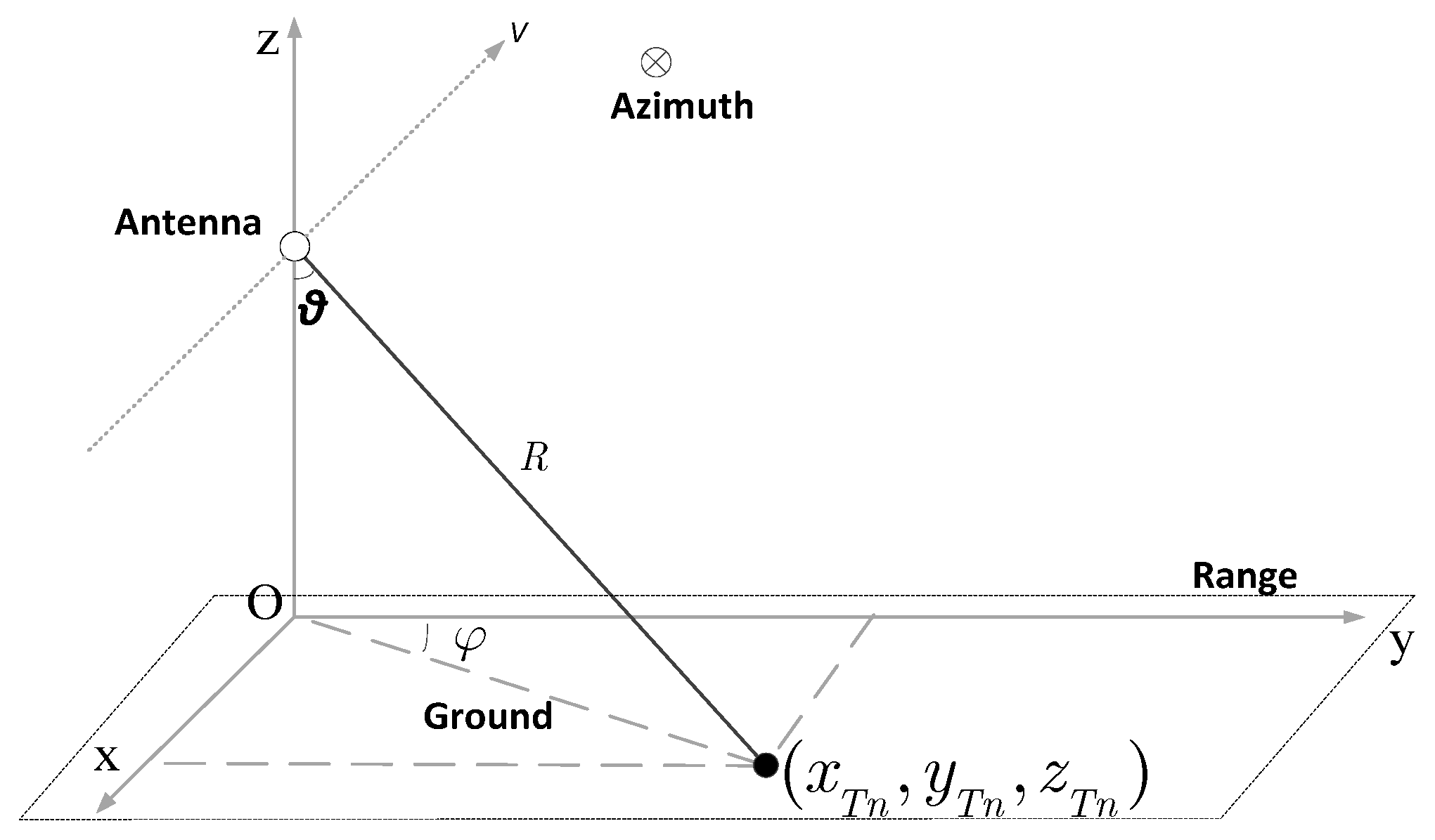
We first established the system coordinate as shown in
Figure 1 below. The x-axis is the azimuth direction, the y-axis is the range direction, and the platform coordinates are (0, 0,
H), where
H is the height of the platform. Elevation angle
θ and azimuth angle
φ are used to represent the position relationship between the antenna and ground scattering point.
When transmitting, the MWE technique can be used to perform different radar functions and meet different practical requirements. In this study, we use the orthogonal waveform sub-pulses of range time domain, which is the simplest form to satisfy the characteristics of STSO waveforms. Assuming that two sub-pulses are transmitted in a PRI, first one is vertically polarized, and the other is horizontally polarized. The echoes of two sub-pulses will be aliased at the receiving end. The transmitting signal after modulation can be given as
where
t is the time variable,
and
are the complex baseband forms of the two transmitting pulses in vertically polarized and horizontally polarized respectively, which are the LFM pulses in this article,
is the time interval between two transmitting sub-pulses,
is the PRI, and
is the carrier frequency. It should be noted here that because our research focuses on achieving waveform separation through DBF along elevation, we ignore partial azimuth characteristics in modeling for the sake of simplicity.
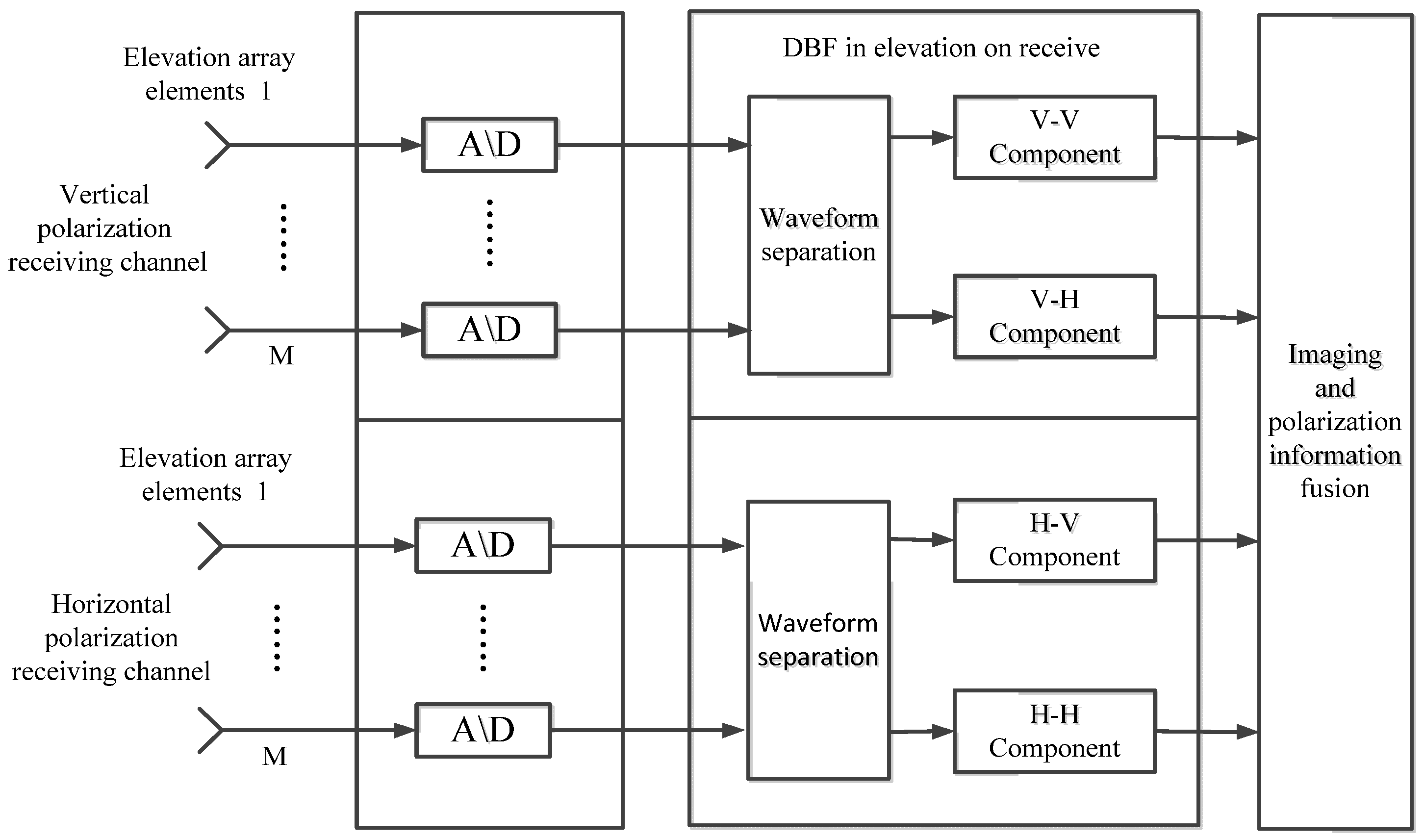
The signal processing block diagram for receiver is shown below in
Figure 2. DBF must be used in elevation to divide the mixed echo signal into two unambiguous signals for two polarized receiving channels respectively. Finally, we can acquire a full polarized SAR image result through imaging and polarization information fusion.
Considering the consistency of the signal processing between the horizontally polarized channel and the vertically polarized channel, here we take the vertically polarized receiver channel as an example in the following model. After demodulation and range pulse compression, the echoes of two sub-pulses in the
k-th period received by the first elevation channel are given by [
18]:
where
and
are the compressed forms of
and
with mainlobe width
,
and
are the ground reflectivity functions of the first array element in elevation for different polarizations within the irradiation range, and
and
are the extended forms of ground reflectivity after demodulation, given by
where
τ is the roundtrip time delay to the first receiving channel in elevation; concurrently, it corresponds to the slant range on the ground, and the elevation angle
can be determined by the slant range and time delay through the geometric model, given by
and
are the transmitting antenna patterns,
and
are the receiving antenna patterns,
and
are the scene scattering coefficients of different polarized channels of two sub-pulses. Thus, the echo of the vertically polarized sub-pulse receiver by the
i-th array element in elevation is written as
Similarly, the echo of the horizontally polarized sub-pulse received by the
i-th array element is given by
The further signal models and difference between , and , will be discussed in the following section for the planar antenna and reflector antenna, respectively.
2.1. Planar Antenna Case
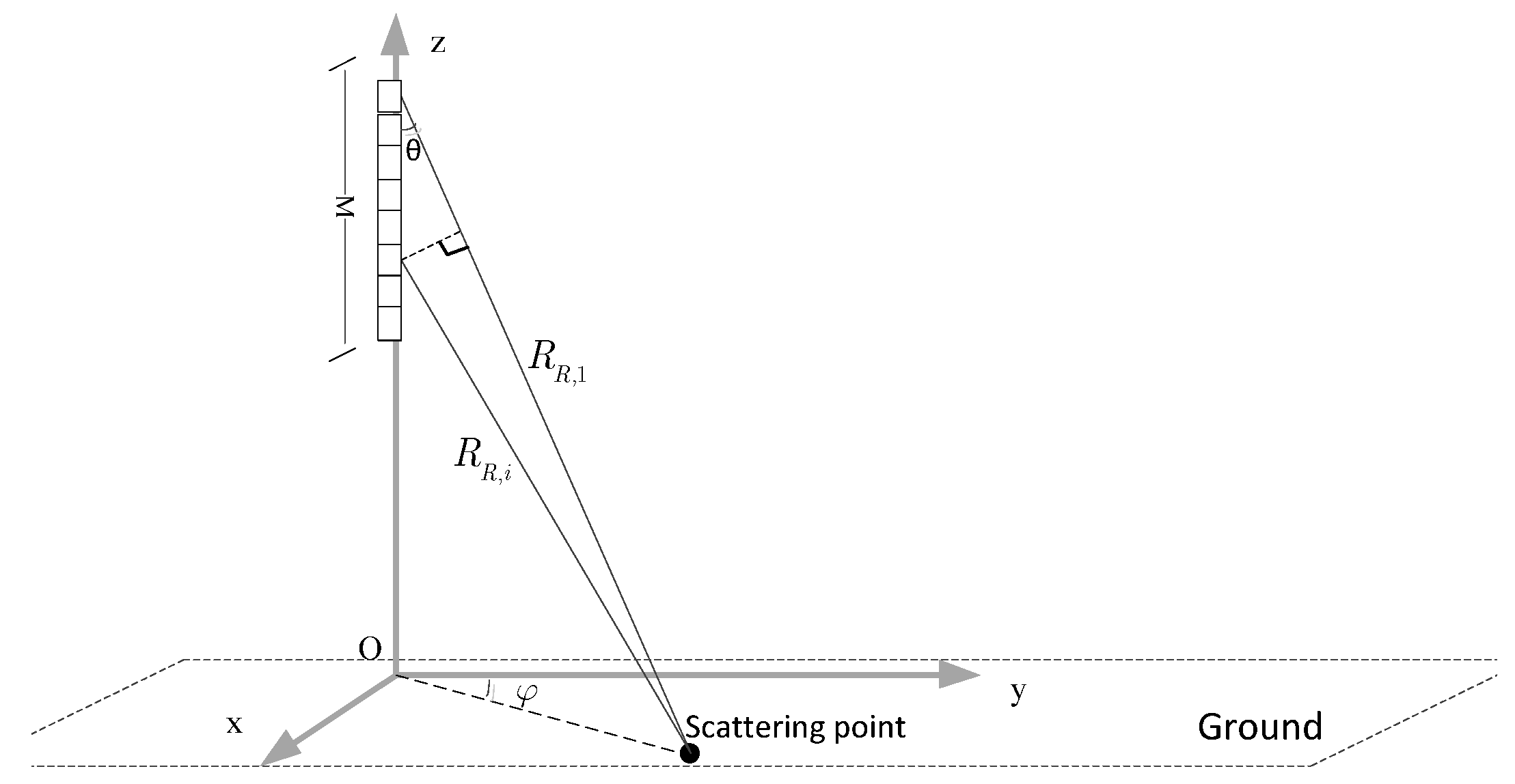
This study mainly focuses on the DBF along elevation so that we assume that there is no ambiguity in the azimuth direction. This means that there is only one transmitting phase center along the azimuth direction. However, the problem is that this can only ensure that there is no ambiguity in the mainlobe, but the sidelobe signal will bring ambiguity too. The specific effects will be analyzed in detail in the following section. Based on this premise, the geometric model of the planar antenna is shown in
Figure 3. Assuming there are
M array elements along the elevation direction:
is the slant range from the first receiving channel to the scattering point on the ground, and
is the slant range from the
i-th channel to the scattering point. Thus, under the far-field approximation:
where
dr is the height of the antenna sub-aperture,
is the elevation angle, and
is the off-nadir angle of the antenna boresight, which is set to
0 in this article. Therefore, there is a difference in the time delay between the two channels for the same scattering point:
For planar antenna, the antenna transmitting and receiving gain are determined by the elevation angle
. Thus, by the approximation of Equation (10), the transmitting gain and receiving gain of different channels for the same target can be considered equal, specifically:
Therefore, the extended ground reflectivity function of the
i-th channel is given by
Thus, we can rewrite the echo receiver by the
i-th array element in elevation as
Similarly, for the horizontally polarized sub-pulse, we can obtain:
Notice that an approximation is made that the trivial variation of
within one range cell is ignored. Finally, we can write the echo of all M array elements in matrix form as
where
is the added noise, and
is an M × 2 matrix:
2.2. Reflector Antenna Case
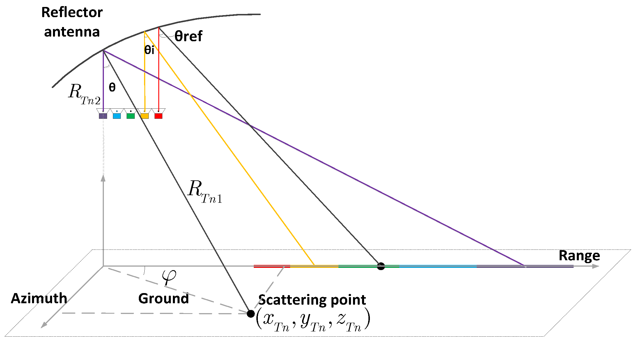
As shown in
Figure 4. Unlike planar antenna where every single array element covers the same wide swath, different array elements in reflector antenna cover different areas (and usually overlap somewhat). Finally, a wide swath like planar antenna is obtained by array elements weighting.
When transmitting, each array element can simultaneously transmit the same pulse. When receiving, the echoes of two transmitting pulses are mixed and received by each array element. The receiver gain depends on the position of the target and the main beam’s irradiating region.
We use following approximate formula to calculate the antenna receiving gain [
26]:
where
is the antenna efficiency and
is the feed element efficiency, which have no effect on our research, so they are set to 1;
is the signal wavelength,
is the aperture diameter, and
is the first order Bessel functions with
defined as
where
and
are the echo’s azimuth and elevation angles,
and
are the azimuth and elevation angles of the
i-th array element’s beam center. Similarly, because this study mainly focuses on the DBF in elevation, we set the azimuth angles
of the all the array elements’ beam centers to be equal to 0. Notice that the azimuth and elevation angles here are calculated in the antenna coordinates system.
For a reflector antenna, the difference of wave paths from the same scattering point to different array elements is so minimal that it can be ignored or corrected in engineering applications [
26,
27]. Thus, unlike the planar antenna, there is no difference in the time delay between the two channels for the same scattering point. However, the receiving gains of different array elements are not same, so Equation (14) changes into
Thus, we can rewrite the echo receiver by the
i-th array element in elevation as
Without a loss of generality, to ensure the unity of form:
In the same way, for the horizontally polarized sub-pulse, we can obtain:
Finally, we can write the echo of all
M array elements in matrix form as
where
is the added noise and
is an M × 2 matrix:
3. DBF Processing in Range-Doppler Domain
3.1. DBF for Waveform Separation
In the previous chapter, we established a signal model for planar antenna and reflector antenna based on STSO signals. From the model, the echo signal models of the two antenna systems can be written in the same form:
For simplicity, we only considered the signals within the mainlobe, and the equation was simplified to
The DBF need constructing a weighting matrix
W to reconstruct the unambiguous signal
.
DBF methods include non-adaptive methods and adaptive methods. Non-adaptive methods such as the least square method only use the steering vector. Therefore, it has poor tolerance for environmental noise, array errors, and so on, which may lead to incomplete suppression of other ambiguity components or self-suppression of signals [
18]. Thus, we chose the adaptive method based on minimum variance distortionless response (MVDR) criterion to perform DBF processing.
This method was originally proposed by Capon, so it is also known as Capon beamforming. Under the minimum noise variance criterion, the output of the signal is guaranteed without distortion and the output power is minimized [
21]:
where
is the covariance matrix of the echo signal, which includes the useful signal part
and the disturbance and noise part
, and
is the steering vector of the signal with the DOA angle of
. Using the Lagrange multiplier method, the solution is
The optimal filter is related to the signal and the steering vector rather than the steering vector alone. This ensures that our proposed method has a greater robustness than the least squares method.
3.2. Steering Vector Mismatch
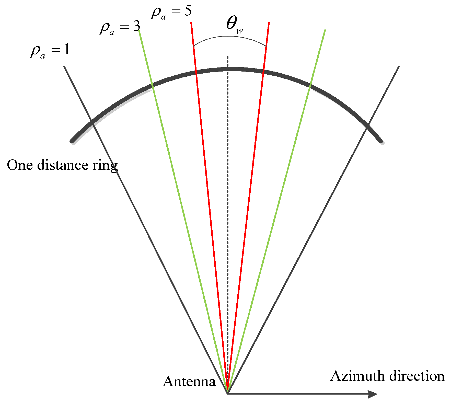
As shown in Equations (18) and (27), the main difference of the echo signal models between two antenna modes is the steering vector matrix . For planar antenna, the difference between two channels’ echoes is mainly resulting from the phase difference caused by the different receiving slant ranges, which is only related to the elevation angle . However, for the reflector antenna, the difference between different channels is caused by the difference in receiving gain, which is related to both the elevation angle as well as the azimuth angle . Simultaneously, is not necessarily related to the time delay, so if we perform the DBF processing in the range-azimuth 2-d time domain like conventional DBF methods for planar antenna, take the average or the maximum in the azimuth, this can lead to a mismatching of steering vectors.
In other words, for the planar antenna, the echo wave paths on a shared distance ring are same; therefore, the steering vector base on the wave path difference and phase difference is not sensitive to whether the echo originates from the beam center or the beam edge. However, as shown in the
Figure 5, Different azimuth positions on the same distance ring have different steering vectors in the reflector antenna. Thus, we cannot simply decouple the azimuth and elevation two-dimensional problem into two one-dimensional problems like planar antenna. Here we also used numerical calculation to observe the effect of steering vector mismatching, as shown in
Figure 6.
As shown in
Figure 6, the higher azimuth resolution, the greater the mismatching. This is because the high resolution corresponds to a wide azimuth beam width
, so the azimuth angle has a wide range of variation. If DBF processing is performed conventionally, the average or the maximum in the azimuth is taken, and the error of the steering vector will greatly affect the system performance.
A simple simulation for observing the waveform separation results under different steering vector mismatches is shown in
Figure 7:
In the figure, if there is no steering vector mismatch, we can achieve ideal waveform separation and ambiguity suppression. With the increase of steering vector mismatch, waveform separation becomes increasingly worse. If we consider a system with a low azimuth resolution; in this case, we can still obtain acceptable separation results, and the amplitude of interference targets are lower than −20 dB. When the azimuth resolution reaches 5 m or worse, the separation performance deteriorates sharply, the interference amplitude is increased to −20 dB while the amplitudes of real targets are attenuated. However, a high azimuth resolution has always been our pursuit for SAR systems. The difference of steering vectors is not negligible for a high azimuth resolution. If we use the conventional DBF technique, if DBF processing is carried out in azimuth-range two-dimensional time domain [
18], it will result in a mismatch of the steering vector. This mismatch will seriously affect the waveform separation as the figure shows, and it will also affect the matching performance in the azimuth. The solution to this mismatch problem will be proposed in the next section.
3.3. DBF in Range-Doppler Domain
Consider the characteristic of SAR in azimuth: When the SAR platform moves, the irradiation area of antenna beam center also moves along the track on the ground. For targets with the same shortest slant range but different azimuth position in the scene, their Doppler history is consistent; this means that the targets with the same shortest slant range have the same characteristics in the range-Doppler domain. The DBF process can be greatly simplified if we convert the azimuth position to the Doppler frequency.
The relationship between Doppler frequency and squint angle is given by
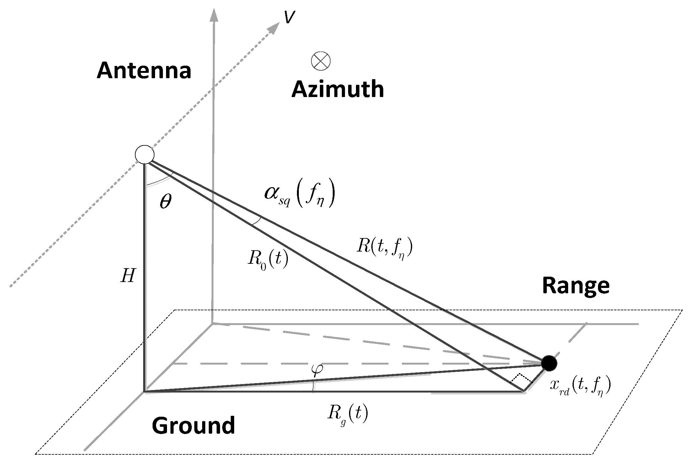
Because the wave path difference between echo and different array elements can be ignored, we can assume that the Doppler frequencies of array elements are all the same. Through Equation (33), we can calculate the squint angle
at different Doppler frequencies. Then, we can calculate the azimuth and elevation angles in antenna coordinate system based on the SAR geometry model, see
Figure 8.
is the squint angle that corresponds to the Doppler frequency
;
is the slant range in the elevation that is a function of range time
. Thus, according to the geometric relations we can obtain:
Then, we can calculate the azimuth and elevation angles in the R-D domain, which is given by
So far, based on the relationship between the azimuth squint angle and Doppler frequency, the steering vector matrix is transformed into a 2-dimensional function of range time and Doppler frequency.
The steering vector matrix generated in the R-D domain of the first sub-pulse is given by
Concurrently, the steering vector matrix of the second sub-pulse is given by
where
Na is the number of azimuth sampling points. Then, we can use DBF for waveform separation in the range-Doppler domain; for the data at different Doppler frequencies, we should use the steering vector that corresponds to the Doppler frequency to do DBF processing. Equations (39) and (40) are written in two dimensions, but this does not mean that the steering vector expands from one dimension to two.
Then, based on the MVDR criterion, the optimal spatial filters for sub-pulses are given by
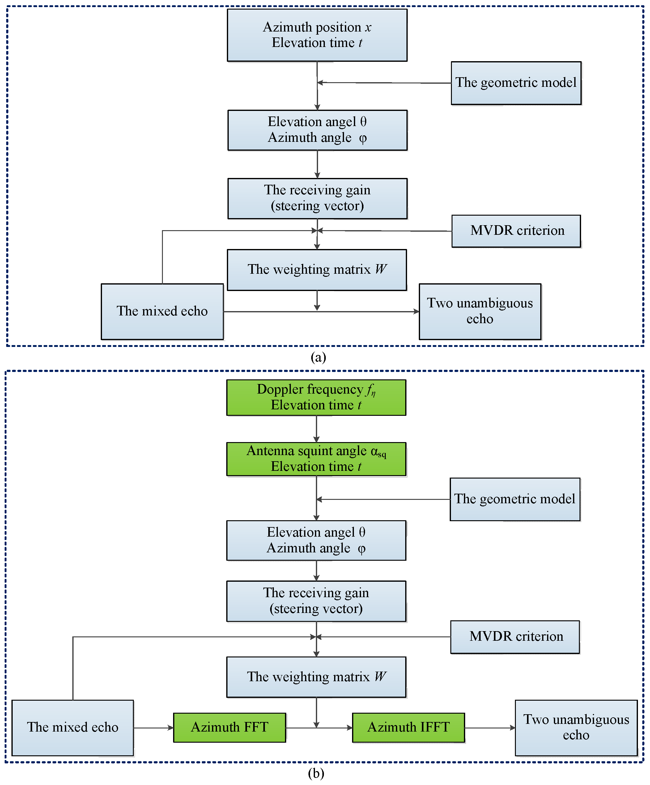
Then, we can separate the waveforms using the spatial filter in the R-D domain; after separation, the conventional SAR imaging methods such as CS can be carried out. The signal processing flow chart of conventional DBF method and proposed DBF method are shown in
Figure 9 below. First, we calculate the squint angle at each Doppler frequency according to Equation (33), and then calculate the elevation angle and azimuth angle through the geometric model shown in
Figure 8, which are used to calculate the receiving gain through Equations (19) and (20). So at this point we obtained the steering vector matrix generated in R-D domain. The next step is to construct the weighting matrix using steering vector matrix based on MVDR criterion. Finally the weighting matrix is used to realize waveform separation, an important thing to note here is that we need to transform echo signal into R-D domain by azimuth FFT. The signal processing flow chart of conventional DBF is also shown in
Figure 9a; we can see that the DBF processing is carried out in the range-azimuth 2-dimensional time domain. One point to pay attention here is that the geometric models for two methods are different.
3.4. Analysis of Azimuth Ambiguity
Although we assumed in
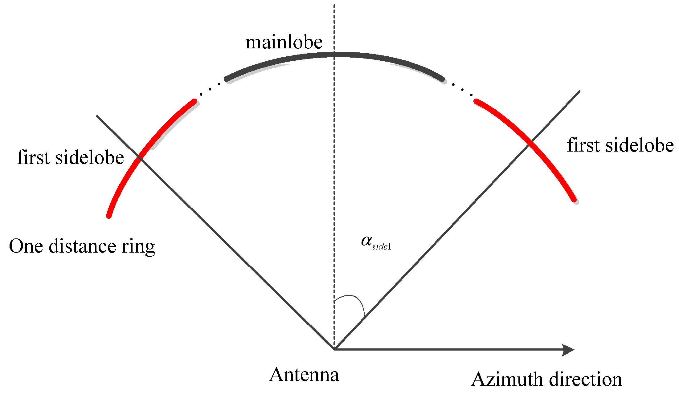
Section 2 that there is no ambiguity in azimuth, this assumption can only guarantee that the mainlobe signal is not ambiguous. The sidelobe signal can also bring ambiguity. If there is ambiguity in the Doppler domain, one Doppler frequency corresponds to more than one azimuth squint angle, so that we could not do DBF processing in the R-D domain. So here we focus on the effect of sidelobe ambiguity.
The azimuth ambiguity is also a problem that can bring steering vector mismatching; The
Figure 5 can be extended to
Figure 10 below:
where
is the azimuth squint angle corresponding to the first sidelobe, is given by
So here we use the method similar to that in
Section 2 to analyze the effect of mismatch caused by sidelobe ambiguity. The result is shown in
Figure 11 below:
We can see that we could suppress the interference by 3dB even though the steering vector of the sidelobe would be seriously mismatched. In consideration of that the amplitude of sidelobe itself is very low, so the overall intensity is still at an acceptable level. Therefore, for the sake of simplicity, we ignored the influence of azimuth ambiguity in modeling, including both mainlobe ambiguity and sidelobe ambiguity. The point targets simulation of sidelobe ambiguity will be shown in the following section.
4. Simulation
Although the application in polarized SAR was proposed in the previous section, the study in this paper mainly focuses on the DBF in elevation on receiver for waveform separation, which has applications not only in polarization SAR but also in many other multi-dimensional observations. The waveforms that carry polarization information or other high dimensional information are identical in the signal processing at the receiving end. So, for generality, we first focused on the results of waveform separation and the polarization characteristics are not considered, and in order to highlight the difference between two echoes for two sub-pulses and make the results clearer, two different SAR original images were selected to generate the echoes of two subpulses respectively in
Section 4.3. Finally, the simulation of the application in fully polarization SAR will be carried out separately in the
Section 4.4.
4.1. Sidelobe Ambiguity Analysis Simulation
In order to verify the analysis, we also carry out a simple point targets simulation to observe the effect of azimuth ambiguity caused by sidelobe. Here we set two targets (A, B), and calculate the position of other two targets that are exactly ambiguous with A and B in azimuth (their Doppler frequencies are one PRF apart). Then, we can compare the results with and without A1 B1 in the simulation, so that we can see the effect of azimuth ambiguity due to sidelobe.
We can see in the
Figure 12 above that there is little deterioration in the performance with the consideration of ambiguous targets, but the difference between two simulation results is very small; both achieve a good waveform separation. Next, we choose a target to further analyze the performance parameters: Resolution, PSLR (Pulse-SideLobe Ratio), ISLR (Intergration SideLobe Ratio) which is shown in the
Table 1 below.
We can see from the table that the performance parameters of the two are basically the same, and the amplitude of the sidelobe can be calculated as
This simple simulation is in line with our theoretical expectations. It can prove that although the impact of the sidelobe will increase the overall interference amplitude, the amplitude of sidelobe itself is very low, so the overall intensity is still at an acceptable level. So, for the sake of simplicity, we ignored the influence of azimuth ambiguity in modeling.
4.2. Point Targets Simulation
Simulation parameters and the targets information are set according to
Table 2 and
Table 3. There are two sets of 10-point targets, which are set to bring range ambiguity exactly.
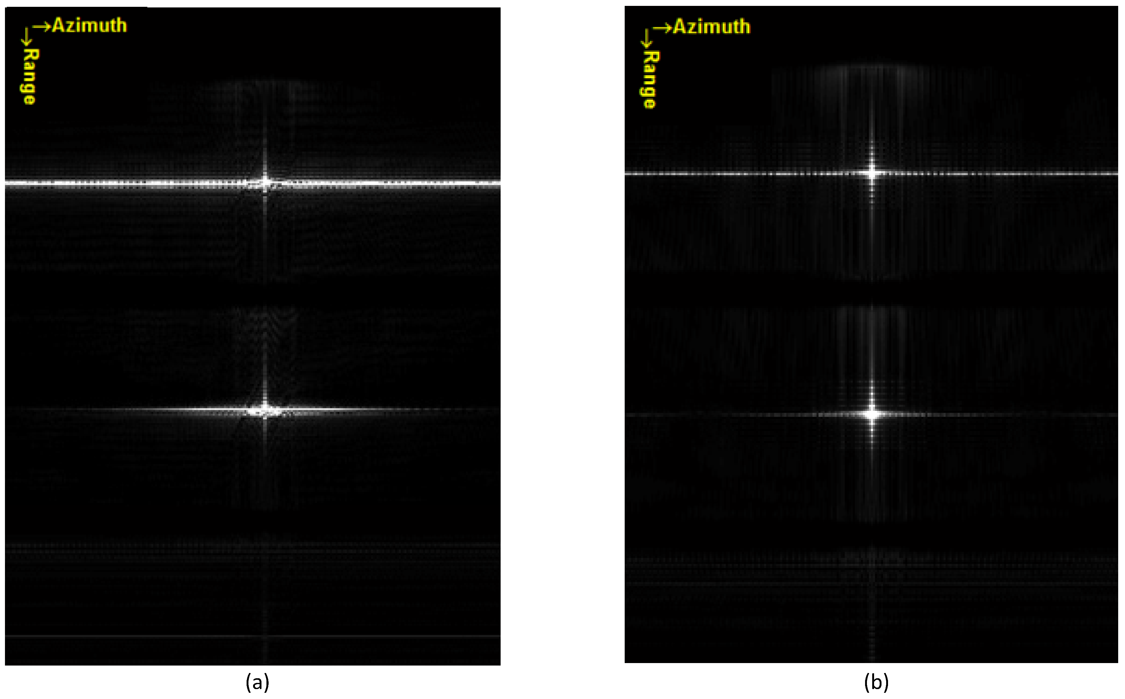
Simulation results for the targets are shown in
Figure 13 below. The DBF method processing in range-Doppler domain successfully separates the two waveforms and obtains the accurate imaging results of 10 targets. Conversely, the conventional DBF that process in the 2-D time domain obviously shows a worse result, especially in the azimuth direction, as is shown in
Figure 13c.
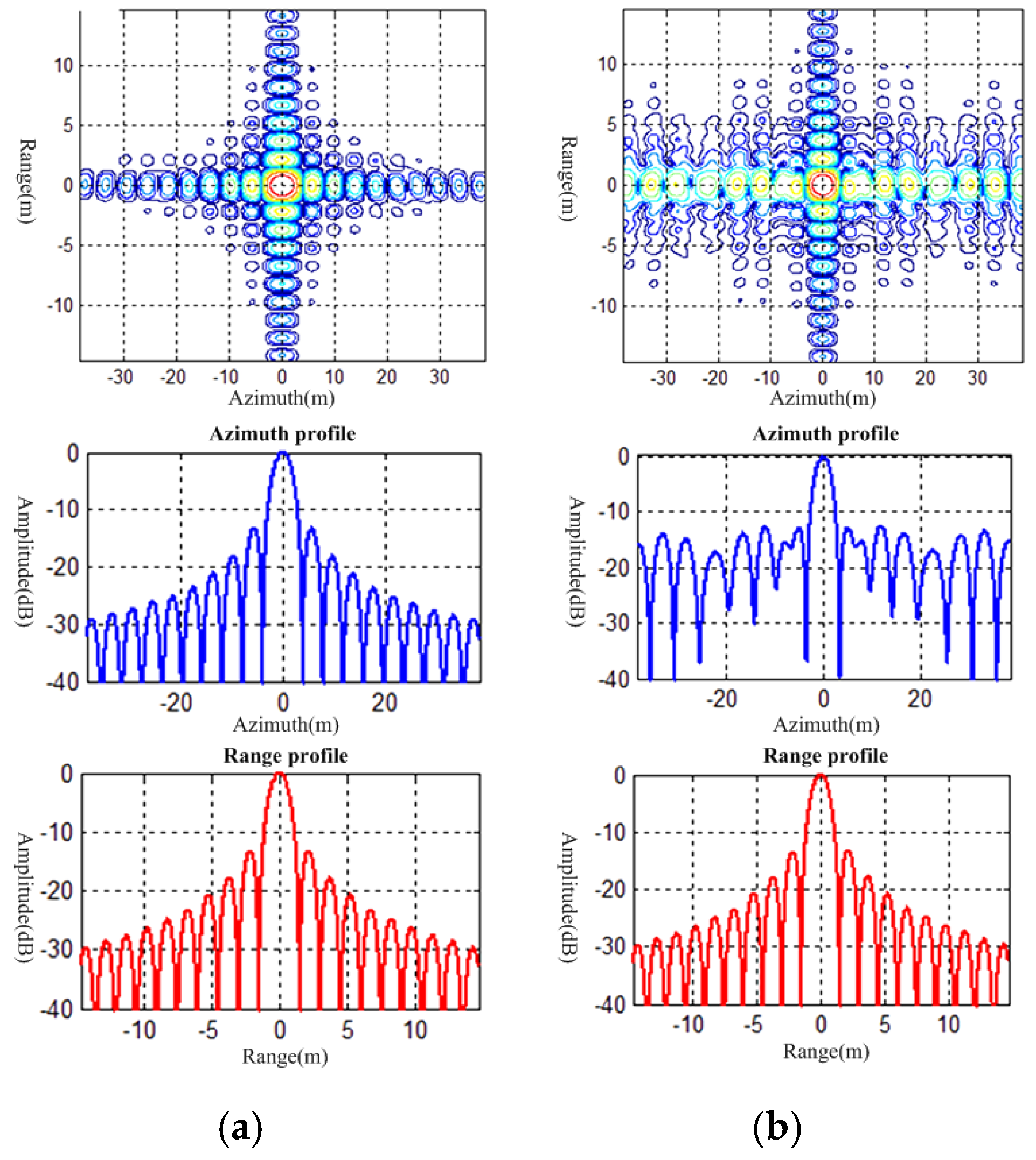
Then, we choose the target in the red box to plot the azimuth and range profiles and calculate the imaging performance parameters for comparison, which are shown in
Figure 14 and
Table 4.
The results show that the DBF in R-D domain can accurately obtain the targets’ position and the performance parameters are kept at an ideal level. However, the conventional DBF method cannot achieve the same effect. We can clearly observe the mismatch in azimuth direction in
Figure 14b, and the comparison of the ISLR in
Table 4 can verify it; this mismatch is unacceptable in practical applications. This problem is caused by the inability to decouple in azimuth-range dimensions.
4.3. Distributed Target Simulation
If we use the point targets echo signal model to generate an echo of a large scene, the calculations are extremely large, and the process is time consuming. Thus, we used inverse Chirp-scaling (ICS) algorithm for echo generation, as it can greatly reduce calculation amount and increase efficiency.
ICS algorithm is the inverse of the CS imaging algorithm, which use SAR image and scene parameters to obtain the original echo data. Then, we can use the echo data to verify the effectiveness and feasibility of the imaging algorithm. For the reflector antenna, determining how to apply the antenna pattern in the inverse CS algorithm becomes the key problem. The antenna pattern is equivalent to adding a “window” to the echo data. For the reflector antenna, this window cannot be easily coupled to the two-dimensional solutions, so the antenna pattern cannot be directly applied to echo data in the time domain. Because the calculation of the receiving gain corresponds to the antenna pattern, the antenna pattern window is applied to the echo data in the R-D domain. The flow chart of the simulation for distributed targets is shown in
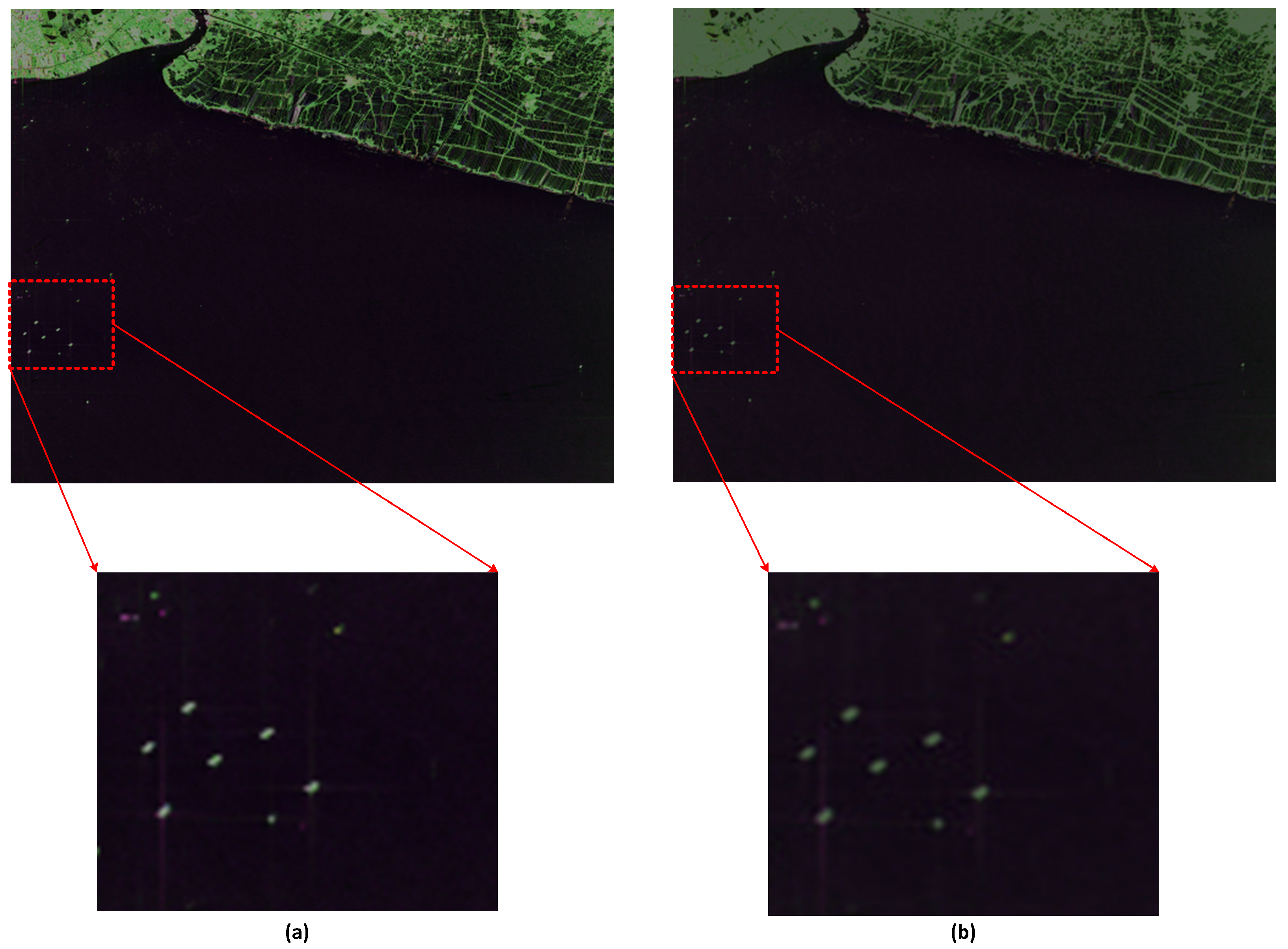
Figure 15 below. To make the simulation results clearer, we selected two different SAR original images to generate the echo signals for two sub-pulses.
The calculated steering vector is stored as a two-dimensional matrix according to the shortest slant range without considering the range cell migration (RCM) phenomenon of SAR echo data. Therefore, before the simulation results are given, the RCM of the steering vector should be compensated. This is the inverse of the range cell migration correction (RCMC) in the imaging algorithm, as shown in
Figure 16 below.
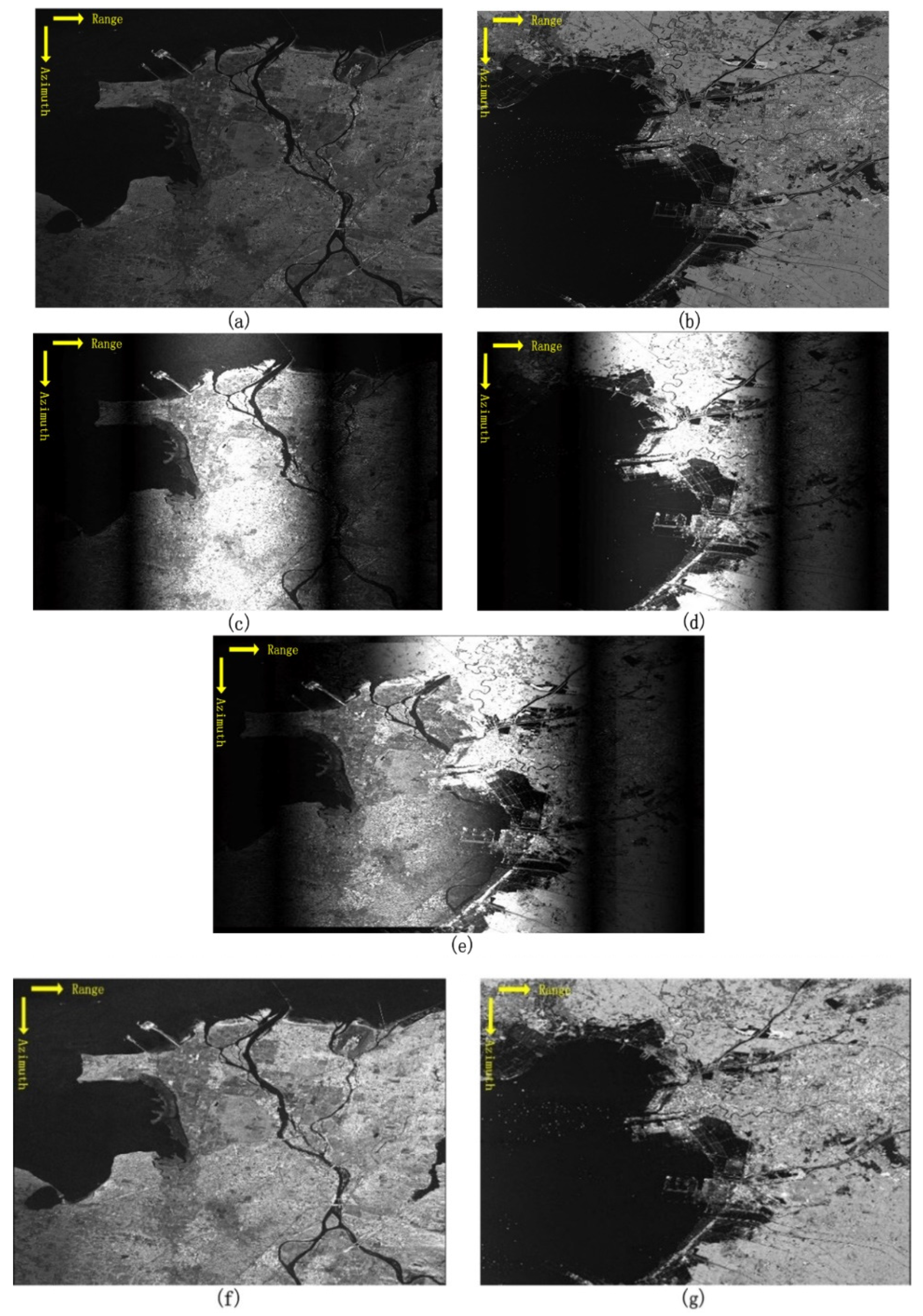
We performed a distributed target simulation according to the flow chart above, and the results are shown in
Figure 17.
As shown in the figure, we used the original radar image data and ICS algorithm to generate the mixed echo signal. First, we considered the case of a single pulse emission; the imaging results are shown in
Figure 17c,d. Then, the imaging result of the mixed echo is shown in
Figure 17e; we can clearly see the range ambiguity. Notice that we only chose one array element to observe the imaging results, so differences can be noted in brightness in
Figure 17c–e owing to the difference in receiving gain. Finally, we used the DBF processing method in the R-D domain mentioned in this paper; the imaging result in
Figure 17f,g shows the feasibility of this method. This method successfully realizes waveform separation and obtained a result that was consistent with the original image.
4.4. Full-Polarization Simulation
In this section, we carried out a simulation to prove the feasibility of application in full-polarization SAR system. First, we chose the full-polarization SAR data of GF-3, the recently-launched Chinese satellite, which is an advanced SAR system with high-resolution and multi-mode working ability. The full polarization observation is one of its operation modes [
31]. The original images of GF-3 are show in
Figure 18 below:
We can see in the figure, there is little difference between the four images. They represent different scene scattering characteristics. The imaging result of fully polarization can be achieved by multiple polarization channels fusion.
Then, according to the simulation process in the
Section 4.3 and the signal processing block diagram in
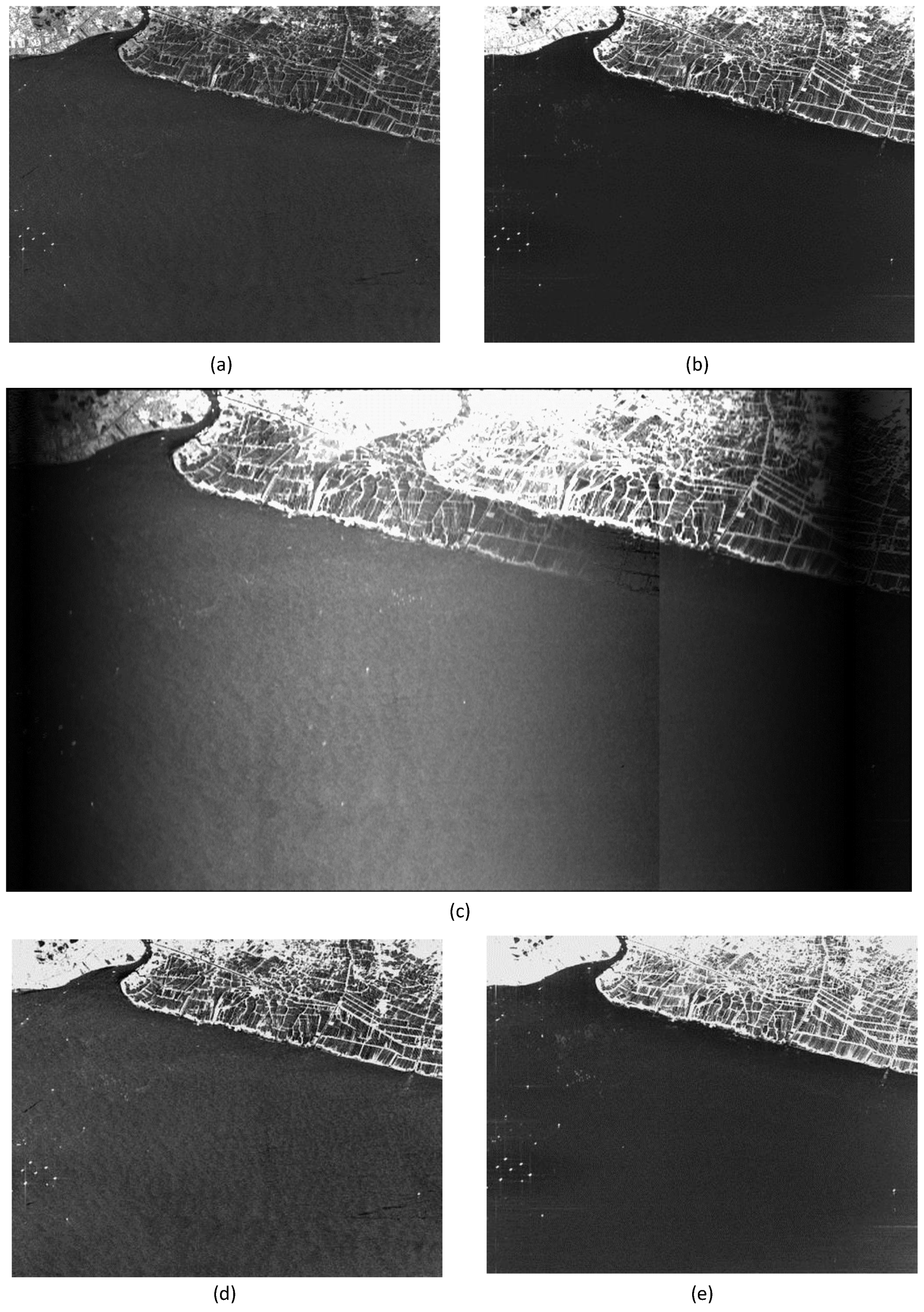
Figure 2, the simulations of waveform separation were carried out for two polarized receiving channels, respectively. Here, for convenience, we only showed the results of vertical polarized receiver channel, as shown in the
Figure 19 below.
We can see in the figure that an undistorted and unambiguous waveform separation was realized. In the same way, the waveform separation for horizontal polarization receive channel was carried out too. Thus, we have obtained the images of four polarizations (HH, HV, VH, and VV). Then we can obtain a full polarization image through polarization information fusion. Here we represent the polarization information by using pseudo-color image. The pseudo-color image was formed by the fusion of HH, HV, and VV polarization channel SAR images. The results are shown in
Figure 20.
As shown in the figure, we can get the same polarization result as the original image. The polarization characteristics remain very well. This simulation proves the potential of the proposed method in polarized SAR system.
However, there is a degree of distortion in
Figure 19 and
Figure 20, especially in the upper part. We can determine that the distortion is due to the ICS algorithm instead of the waveform separation algorithm. Maybe it is caused by improper setting of system parameters, different dynamic range of image display, the scale change of image in simulation, and so on. However, as we have been emphasizing, our study focus was on waveform separation through proposed DBF method, so the effect of ICS algorithm on the image was not studied intensively in our study.
6. Conclusions
This study focuses on the MIMO SAR system based on the array-fed reflector antenna. We simultaneously combined the combination of orthogonal waveforms in different polarizations and DBF technology in elevation at the receiving end; this method can greatly improve system performance, especially ambiguity suppression, waveform separation, and fully polarized observation. However, owing to the substantial differences in their methodological underpinnings, unlike the planar antenna, it is difficult to decouple the azimuth and elevation two-dimensional problem into two one-dimensional problems when waveform separating. Thus, we propose a DBF method processing in range-Doppler domain to solve this problem. The simulation results show the correctness and feasibility of this method, which can obtain the ideal image without range ambiguity. The simulation for full polarization SAR can also show the great potential of the proposed method in the applications of multi-dimensional radar observation.
However, there is a limitation to the proposed DBF method, which is the assumption mentioned in the
Section 2. We can achieve waveform separation in R-D domain only if there is no ambiguity in azimuth direction. This is hard to fully satisfy in practical applications. If there is ambiguity in the Doppler domain, one Doppler frequency corresponds to more than one azimuth squint angles, so that we could not do DBF processing in the R-D domain. How to realize waveform separation when there is ambiguity in both range and azimuth direction is also our next research goal. There are two thoughts to solve this problem. One of our ideas is that if we could decouple the antenna pattern like
through the design of antenna, including the reflector shape or the placement of the array elements. Then this 2-dimensional coupling problem can be simplified to two 1-dimensional problems. For example, maybe we can solve the problem by using elliptic shaped antenna or offset-focus parabolic antenna and so on instead of rotational parabolic antenna; however, this idea puts forward higher requirements for system design and also increases the cost and complexity of antenna. Another promising way is to improve the signal processing algorithm without changing the reflector shape. We can use a cascade system, first remove the azimuth ambiguity through DBF in azimuth (or DPCA technique etc.), and then we can separate the mixed echoes by using the proposed method. Another thought is to use a two-dimensional array, and then we can use a 2-dimensional DBF method, which separates the mixed echo and remove the azimuth ambiguity simultaneously. However, this solution has a high requirement on the signal processing capability and system freedom.
