Article

Inter-Calibration of AMSU-A Window Channels

1
I. M. Systems Group, 5830 University Research Court, College Park, MD 20740, USA
2
Center for Satellite Applications and Research, National Environmental Satellite Data and Information Service, National Oceanic and Atmospheric Administration, 5825 University Research Court, Suite 4001, College Park, MD 20740-3823, USA
3
Global Science and Technology, Inc., 5830 University Research Court, College Park, MD 20740, USA
*
Author to whom correspondence should be addressed.
Remote Sens. 2020, 12(18), 2988; https://doi.org/10.3390/rs12182988
Submission received: 4 August 2020 / Revised: 31 August 2020 / Accepted: 9 September 2020 / Published: 14 September 2020

Abstract

:
More than one decade of observations from the Advanced Microwave Sounding Unit-A (AMSU-A) onboard the polar-orbiting satellites NOAA-15 to NOAA-19 and European Meteorological Operational satellite program-A (MetOp-A) provided global information on atmospheric temperature profiles, water vapor, cloud, precipitation, etc. These observations were primarily intended for weather related prediction and applications, however, in order to meet the requirements for climate application, further reprocessing must be conducted to first eliminate any potential satellites biases. After the geolocation and cross-scan bias corrections were applied to the dataset, follow-on research focused on the comparison amongst AMSU-A window channels (e.g., 23.8, 31.4, 50.3 and 89.0 GHz) from the six different satellites to remove any inter-satellite inconsistency. Inter-satellite differences can arise from many error sources, such as bias drift, sun-heating-induced instrument variability in brightness temperatures, radiance dependent biases due to inaccurate calibration nonlinearity, etc. The Integrated microwave inter-calibration approach (IMICA) approach was adopted in this study for inter-satellite calibration of AMSU-A window channels after the appropriate standard deviation (STD) thresholds were identified to restrict Simultaneous Nadir Overpass (SNO) data for window channels. This was a critical step towards the development of a set of fundamental and thematic climate data records (CDRs) for hydrological and climatological applications. NOAA-15 served as the main reference satellite for this study. For ensuing studies that expand to beyond 2015, however, it is recommended that a different satellite be adopted as the reference due to concerns over potential degradation of NOAA-15 AMSU-A.

Graphical Abstract

1. Introduction

Satellite measurements and derived meteorological products from the Polar Operational Environmental Satellite (POES) system have demonstrated their capability in Numerical Weather Prediction (NWP). The long time series of these measurements make them candidates for use in climate monitoring and assessment. In 2004, a panel of experts convened and developed a strategy for the generation of Climate Data Records (CDR) from satellite observations [1]. In that document, CDR was defined as “a time series of measurements of sufficient length, consistency, and continuity to determine climate variability and change”, and segmented into Fundamental CDR (FCDR), at the radiance/reflectance level, and Thematic CDR (TCDR), at the geophysical product level. Thereafter, National Oceanic and Atmospheric Administration (NOAA)’s National Climatic Environmental Information (NCEI) launched the NOAA’s CDR program, which included several types of CDRs, including atmospheric and sea surface temperatures, snow and ice conditions, precipitation and clouds.
In order to achieve CDR quality from a satellite time series like AMSU-A, which has spanned seven different satellites since 1998, inter-satellite calibration is perhaps the most critical step, and is commonly accomplished through direct comparisons of collocated observations from pairs of satellite instruments (i.e., NOAA-15 with NOAA-16, etc.). Through these comparisons, systematic calibration transfer functions can be generated to correct the radiometric biases of the monitored sensors in References [2,3,4]. Numerous inter-satellite calibration approaches have emerged recently, and can be classified into two broad categories according to their sensor scanning types: simultaneous nadir overpass (SNO) for cross-track scanning sensor pairs like AMSU-A [5] and simultaneous conical overpass (SCO) for conical scanning sensor pairs like the Special Sensor Microwave Imager (SSM/I) [6]. SCO uses relatively stable on-Earth targets as references for sensor comparisons, e.g., vicarious cold target [7] and warm target [8], because of the relatively stable earth incidence angle of the conically scanning instruments. To introduce cross-platform calibration (XCAL), a unified calibration was developed to adapt comparison results from a group of approaches [9]—most of these approaches have been applied to the SSM/I to develop its FCDR [10].
The space-borne passive microwave measurements, especially from Advanced Microwave Sounding Unit-A (AMSU-A), first launched on May 13, 1998 onboard NOAA-15 (N15), and later NOAA-16 (N16) through NOAA-19 (N19), and the European Meteorological Operational satellite program-A (MetOp-A), have been identified as the largest contributor to the improvement of the global 24-h forecast skills by about 25% [11]. Among the fifteen AMSU-A channels, Channels 1–3 and 15, with the nominal central frequencies at 23.8, 31.4, 50.3 and 89.0 GHz, are collectively referred to as window channels, as their weighting functions peak at or near the surface, and they are more transparent in the atmosphere than other channels. Radiances and Brightness Temperatures (TB’s) from these channels are operationally used by two product systems at NOAA’s National Environmental Satellite, Data and Information Service (NESDIS): the Microwave Surface and Precipitation Products System (MSPPS) [12], and the Microwave Integrated Retrieval System (MIRS) [13], to retrieve a suite of hydrological products, including cloud liquid water (CLW), total precipitable water (TPW), sea ice, snow cover, as well as relevant variables, including land surface temperature and surface emissivity of 23.8, 31.4 and 50.3 GHz. Radiance observations of these channels are also routinely assimilated into NWP and reanalysis systems such as Climate forecasting System Reanalysis (CSFR) [14] and the Modern-Era Retrospective Analysis for Research and Applications (MERRA) [15]. It should be noted that, even though the AMSU-A temperature sounding data is assimilated in ERA-Interim [16], which is produced by European Center for Medium-Range Weather Forecasts (ECMWF), AMSU-A window channels are not included [16].
As a follow on study from our previous geolocation [17] and cross-scan bias corrections [18], the main goal of this work is to inter-calibrate the window channels of AMSU-A instruments onboard six satellites to a common calibration standard for use in developing CDRs. After an exhaustive trial of several methods, such as vicarious cold reference, and various SNO approaches in the earlier stage of the study, we selected the IMICA algorithm for the intersatellite calibration of AMSU-A window channels. This approach, developed by Zou et al. [19,20], extensively uses SNO to solve calibration coefficients and remove/minimize inter-satellite biases, captures the major causes of the inter-satellite inconsistency, and accounts for scene homogeneity, etc. Note that until now almost all published inter-calibration work related to AMSU-A have focused on the sounding channels in the oxygen absorption region, which are Channels 4–14, and their corresponding physical variables. For instance, the work in Reference [19] inter-calibrated FCDR for these sounding channels, and produced TCDR of atmospheric temperature at different atmospheric levels from the FCDR, while the work in References [21,22] produced temperature TCDR using operationally calibrated brightness temperatures. In comparison, physical variables from window channels are more closely related to the surface (e.g., see ice and wind speed over the sea), precipitation, and integrated atmospheric water since these channels are sensitive to water vapor and liquid water emission. Inconsistency in the data set may cause various problems in the follow on applications. For instance, according to Robertson et al. [23], it is primarily through the window channels that the AMSU-A instrument can affect the water vapor increments in MERRA.
This paper is organized as follows. Section 2 presents the materials and methods, including the simultaneous nadir overpass (SNO) method and how it is used in our application, the Integrated Microwave Inter-Calibration Approach (IMICA) used to correct the warm target contamination and non-linearity problem, and two other error sources: bias drift and frequency shift. Section 3 demonstrates the effectiveness of the inter-satellite calibration approaches through time series of both FCDR and TCDR. Further discussions and concluding remarks are presented in Section 4.

2. Materials and Methods

2.1. Sno Overview

Originally proposed by Cao et al. [24], the simultaneous nadir overpass (SNO) approach is widely used to perform inter-satellite calibration for both microwave sensors [5,19] and infrared sensors [25,26] onboard polar orbiting satellites. “Nadir” refers to the observations with a zero degree of sensor scan angle or earth incidence angle, so as to eliminate uncertainties associated with difference of atmospheric paths and viewing geometries. Since AMSU-A does not have nadir observations, the two observations closest to nadir were combined as the nadir scene. “Simultaneous” requires temporal and spatial restrictions to describe the event of two satellites meeting. These requirements typically vary depending on the sensor configuration and orbital overpass times and may limit the number of SNO’s. There are some general rules for selecting the spatial and temporal thresholds for SNO. In considering spatial threshold, it is optimal to adopt a distance between the nadir scenes of the two satellites close to the sensor spatial resolution [20]. For AMSU-A, the spatial threshold should be about 50–75 km since its nadir field of view is 48 km. The major consideration for temporal restriction is the tradeoff between observational change and the number of matches. A temporal threshold of 50 s was used in this study to provide an adequate number of matchups and still maintains any meteorological changes at a minimum. Further discussion about this threshold is provided later in this paper. Additionally, for the AMSU-A window channels, special consideration must be taken to ensure that the pair of nadir observations is homogenous, as they are much more sensitive to the surface compared to the sounding channels [20]. Sensitivity tests were performed, following the investigation of SNO performance of all the satellite pairs, which confirms that our selections of SNO thresholds are valid.

2.1.1. Temporal Features and Number of SNO Pairs

Due to the different orbital configuration of each NOAA and MetOp satellite, such as the time of local ascending node, altitude, inclination, orbital drift rate, and central frequencies of window channels (Table 1 and Table 2, and more details in Reference [27]), patterns of SNO events vary between different pairs of satellites. For example, SNO events occur between N15 and N16, roughly every 8 days, while SNOs between N18 and N19 occur in 8 consecutive days when their orbits are close, but then, SNO’s do not occur for over 300 days. A comprehensive list of the SNO overlap and interval patterns is given in Table 3.
Note the numbers in Table 3 are average numbers for the period of record. There are slight variations over the period of satellite operation due to changes in satellite drifts. For example, in early 2001, the SNO interval time for the N15 vs. N16 pair was 8.07 days, this interval time increased to 8.20 days when it had a global SNO in August 2008, and stepped down to 8.17 days in late 2010.

2.1.2. Spatial Features

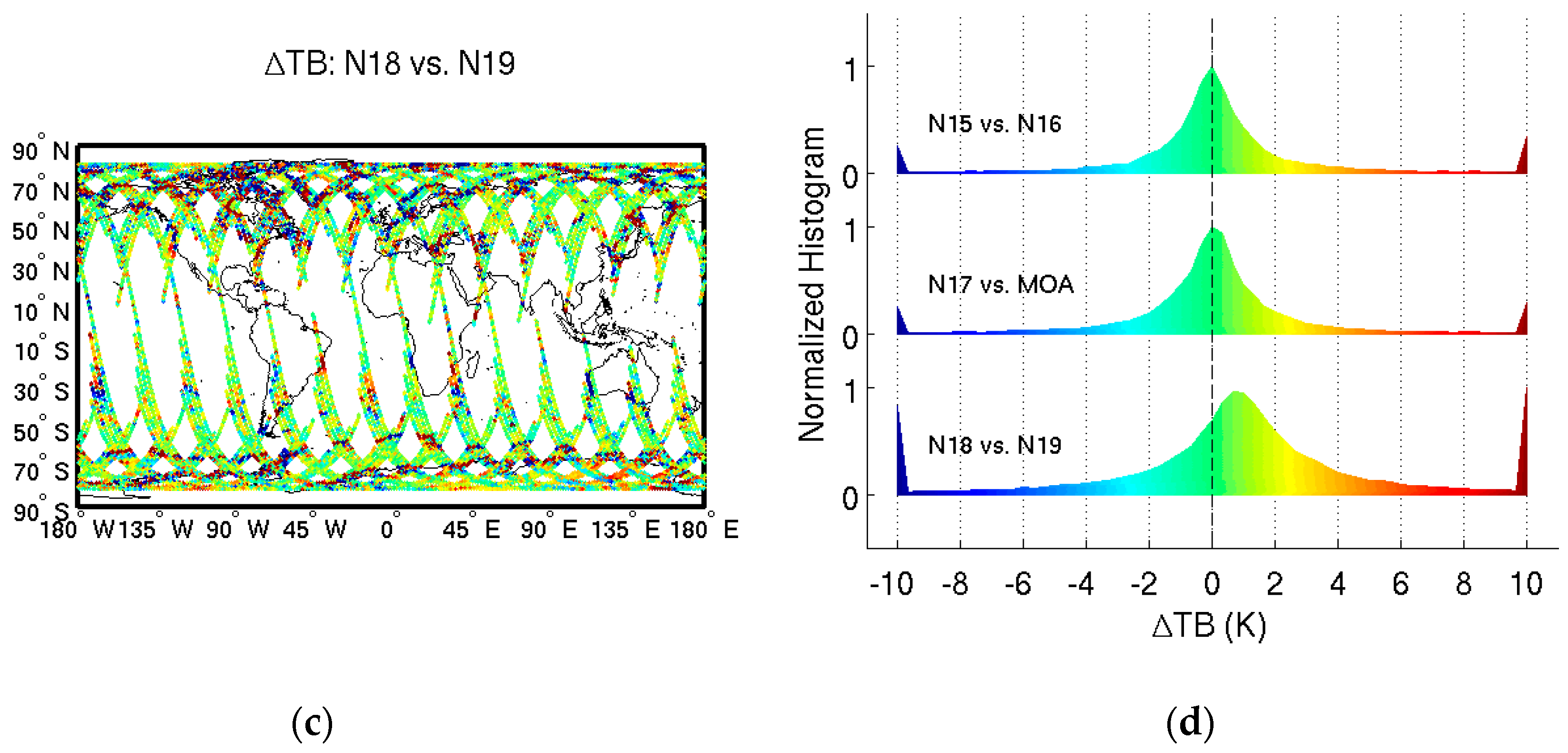
Due to the orbital properties of sun synchronous, polar orbiting satellites, most SNO events between satellite pairs occur near polar regions over the 70°N to 80°N and 70°S to 80°S bands [20,24]. In some instances, an SNO could occur at lower latitudes, which provides additional information on inter-satellite differences in warmer atmospheric conditions and allows for a wider dynamic range to perform the inter-satellite calibration. [28]. Figure 1 shows the global SNO for three satellite pairs: N15 vs. N16 in August, 2008, N17 vs. MetOp A in April and May, 2009, and N18 vs. N19 in September, 2009. Using the time and space criteria of 50 s and 50 km, respectively (N18 vs. N19 pair needs a larger distance of 75 km to allow for enough number of observations due to their very close equatorial crossing times), SNOs occurred at all latitudes between 81°S to 81°N. As can be seen, the differences at 23.8 GHz brightness temperatures are mostly within 3 K, and the largest TB differences come from coast regions. Global SNO greatly enhances the spatial coverage and number of observations for further analysis.

2.1.3. Brightness Temperature Time Series of SNO Pairs

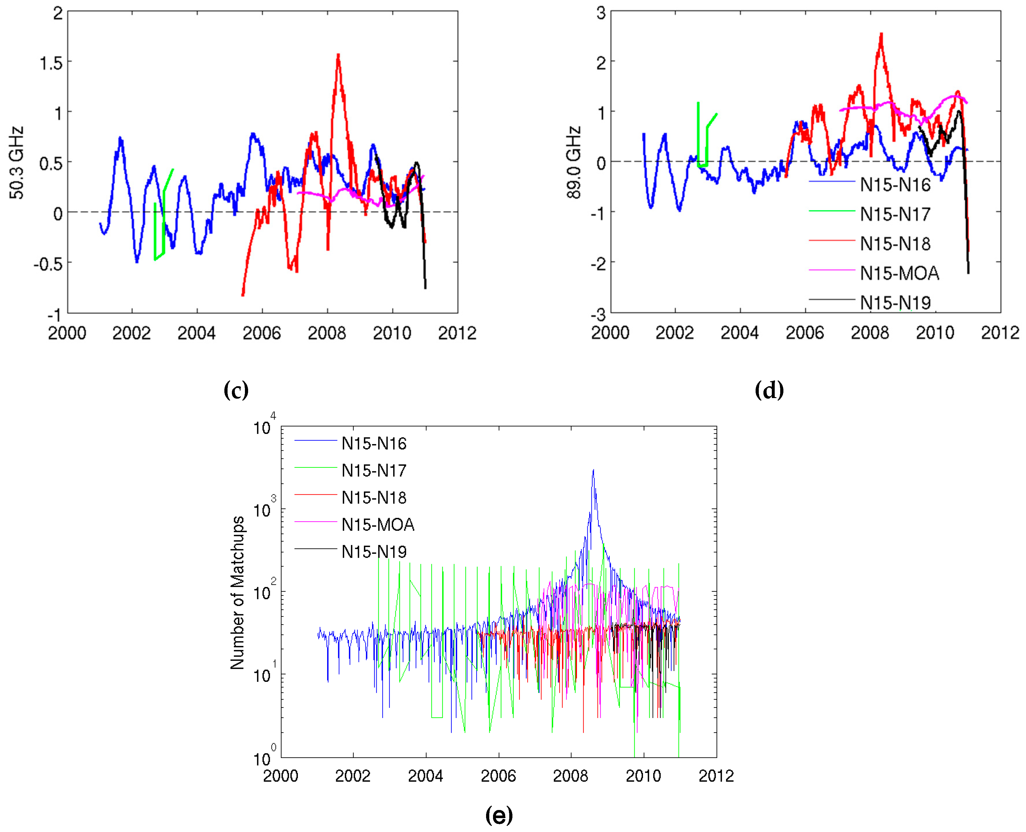
After investigating the overlap pattern and spatial distribution of the SNO, the next step is to evaluate the TB difference time series, which provides the opportunity to gain a better understanding of the inter-satellite differences. Figure 2 shows the SNO time series between AMSU-A onboard N15 with other satellites, i.e., N16 through the N19 and MetOp-A. N17 AMSU-A1 modules (containing 50.3 and 89 GHz) stopped working in November 2003. However, the AMSU-A2 module continued to operate, and thus, the time series of 23.8 and 31.4 GHz channels could extend through 2010. Nevertheless, the N17 time series generate the most outliners, especially for 23.8 and 31.4 GHz channels. In most cases, the TB difference is within 3 K, which is consistent with the observations in Section 2.1.2 and Figure 1.
The brightness temperature difference (ΔTB) of SNO pairs may come from various sources. For instance, Table 1 also lists the central frequencies of these AMSU-A window channels onboard difference satellites, and one can find that they fall into two groups: the first group includes NOAA-15 and NOAA-16, and the second group includes the other satellites. The channels within a group are generally the same, but there is a slight difference between different groups, e.g., 0.8 MHz difference for 23.8 and 50.3 GHz channel, 0.3 MHz difference for 31.4 GHz channel, and 60 KHz difference for the 89.0 GHz channel. In addition, although we have applied a geolocation correction [17], there still might be residual variations in view angles. These sensor factors inevitably lead to systematic ΔTB, although they might be small and hard to quantify as separate error components.

2.1.4. Sensitivity Test of Brightness Temperature Difference

Figure 1 and Figure 2 display the spatial and temporal distributions of brightness temperature differences (ΔTB) between the nadir scenes of the SNO satellite pairs. Since the AMSU-A window channels, i.e., 23.8, 31.4, 50.3, and 89 GHz, are sensitive to surface conditions, we need to examine the impact of certain factors on the ΔTB between satellite pairs. These factors include the distance between the nadir scenes of the satellite pairs, time difference between the satellite pairs passing over the same location, and brightness temperature contrasts (BTC) between the two central observations, i.e., beam positions 15 and 16 of AMSU-A, which together form the nadir scene. Note that BTC is computed for each individual satellite within the SNO satellite pairs. A large value of BTC indicates that the observations from the two beam positions may come from different surface types, e.g., one beam position is mainly observed over ocean while the other is mainly over land. This is the primary difference between window channels and sounding channels, since the latter are not sensitive to various surface types. Table 4 shows the average correlation coefficients between SNO ΔTB and various factors from more than 50,000 SNO occurrences. Higher absolute values in Table 4 indicate more important factors.
The sensitivity test reveals that the BTCs of both satellites produce the largest correlation coefficients with ΔTB so BTC serves as the most important factor to explain the variation of ΔTB. A small BTC usually suggests that the scene is more homogeneous and leads to small ΔTB and vice versa. For this reason, the BTC information is used to screen out the potential inhomogeneous SNO pairs. In contrast, the distance between satellite pairs can only explain a fraction of the ΔTB variation since a longer distance may potentially increase the possibility of having different surface types between observed scenes. Finally, the time difference between the satellites essentially plays no role in explaining any differences, as both the atmospheric and surface conditions are relatively stable within the time frame of 50 s. For this reason, the time difference threshold is more relaxed in some studies, e.g., it was 300 s in the study by John et al. [28]. In our study, the time difference relates more to the number of matchup observations. As the number of polar SNOs was large enough, and the number of global SNO was mainly determined by the meeting collocation pattern of satellite pairs (Section 2.1.2), we kept the time difference at 50 s.
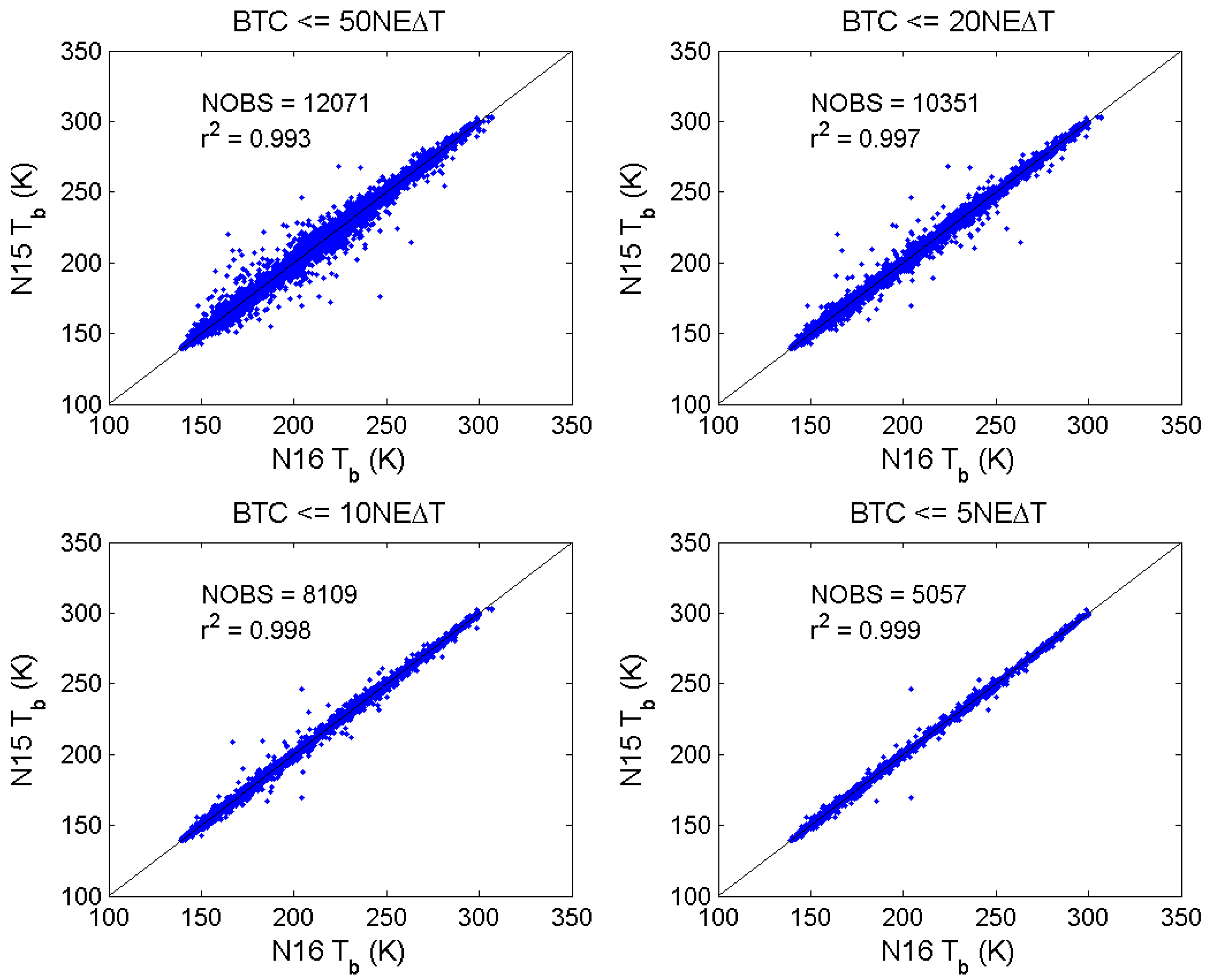
Optimizing the uncertainties of inter-satellite SNO ΔTB requires a proper threshold for BTC that is small enough to ensure scene homogeneity, yet large enough to allow for a sufficient number of observations (NOBS). Since these channels have different sensitivities to the surface, the BTC threshold can vary with channels. A series of sensitivity tests were performed based on NEΔT using the SNO matchups between N15 and N16 (Figure 3). Based on the analysis, the threshold was set at 10xNEΔT.

2.2. Warm Target Contamination and Correction

The inter-satellite differences of ΔTB revealed some inter-calibration issues, such as bias drift, sun-heating-induced instrument variability in TB, scene temperature dependent biases due to inaccurate calibration nonlinearity, and frequency shifts [19]. Among them, the warm target induced bias and the inaccurate calibration nonlinearity impacted the measurements in the entire life span of the instrument—these were the primary biases to investigate and correct.

2.2.1. Identification of Warm Target Contamination

The AMSU-A instrument onboard each satellite measured counts of three objects in each full scan: cold target ( C c ), warm target ( C w ), and earth scene ( C e ). The radiances of cold target ( R c ) and warm target ( R w ) were also measured to calculate earth scene radiance ( R ) through the following series of equations [29]:
R = R L + μ Z
R L = R c + S ( C e C c )
S = R w R c C w C c
Z = S 2 ( C e C c ) ( C e C w )
Equation (1) decomposes the earth scene radiance into a linear part ( R L ) and a non-linear part ( μ Z ). The two parts were further described in Equations (2) and (4). The non-linear coefficient μ was calculated from the reference instrument temperature in a pre-defined range in the Level 1b data before inter-satellite calibration.
Cold and warm targets were designed to provide reference radiances for on-orbit calibration to obtain accurate earth scene radiance, so it was ideal for these radiances and TBs to be stable. The cold target temperature was relatively stable, given that the cosmic background should not vary very much in the life span of the sensors. An exception is lunar contamination, which was well detected and corrected [30]. The contamination of the cold space view from antenna side/back-lobes/spillover may also introduce bias, and was corrected beforehand [31]. The warm target, however, may be heated by the sun and is susceptible to seasonal and inter-annual variability, as shown in Figure 4. The variability of warm target temperature was explained well using the solar beta angle in Reference [19]. Figure 4 shows that 23.8 and 31.4 GHz channels have similar variabilities as they both reside on the AMSU-A2 module, while the variability of 50.3 and 89 GHz are similar because their sub modules (AMSU-A1-2 for 50.3 GHz channel, and AMSU-A1-1 for 89 GHz channel) are close to one another on the spacecraft. The NOAA-16 warm target temperature was rather stable before 2008, mainly due to the fact that the satellite solar shield worked well during that period and reflected a large portion of solar heat.

2.2.2. Correction Utilizing Integrated Microwave Inter-Calibration Approach

The Integrated Microwave Inter-Calibration Approach (IMICA), developed by Zou et al. [19,20,32,33], has demonstrated the calibration coefficients obtained from regressions minimize three biases: constant offsets between satellite pairs, scene temperature dependent biases between satellite pairs, and the sun-heating induced seasonal variability in brightness temperature. When the coefficients are time-varying, the coefficients also remove bias drifts over time between satellite pairs. It is effective for AMSU-A temperature sounding channels. The IMICA approach was adopted in this study for the inter-satellite calibration of AMSU-A window channels in order to remove the biases in an empirical way by adjusting the transfer function that converts counts to radiance, after certain modifications are made, e.g., the application of appropriate standard deviation (STD) thresholds to filter the SNO time series.
In the IMICA approach, Equation (1) is modified to
R = R L δ R + μ Z
where the radiance offset δ R allows for adjustments of the inter-satellite radiance difference, and the non-linear coefficient μ is redefined and calculated, as described below following [19]. It is noted that the non-linear coefficient in the text refers to this inter-calibrated, redefined μ . Firstly, the non-linear term, Z , of the two satellites can be linearly related as:
Z j = β Z k + α + ζ
where β and α are slope and offset, respectively, ζ is a white noise, and j and k indicate the two satellites, respectively. Secondly, the variability of Equation (5) can be obtained through a least square calculation as:
{ i = 1 N Δ R L , i = a 0 + a 1 i = 1 N Z k , i i = 1 N Z k , i Δ R L , i = a 0 i = 1 N Z k , i + a 1 i = 1 N Z k , i 2
where i represents different observations, Δ R L refers to the difference of R L between the two SNO matchup satellites, and the newly introduced coefficients a 0 and a 1 can be linked back to other variables such as
{ a 0 = Δ δ R + α μ j a 1 = μ k + β μ j
By obtaining the coefficients α , β , a 0 and a 1 , one can calculate Δ δ R (the difference of δ R between the two SNO satellites), μ j and μ k Then, δ R j can be determined by setting the reference δ R k to zero.
In order to achieve the optimum results for all six satellites of interest, a sequential adjusting process was applied and is described below:
1. Generate intermediate SNO data set from the launch of the newer satellite of the satellite pair to 2010, which includes multiple intermediate variables, including time, latitude, longitude, brightness temperature, counts, radiance, etc., for each SNO event;
2. Filter this data set by the BTC threshold described in Section 2.1;
3. Calculate SNO coefficients ( α , β , a 0 and a 1 );
4. Set δ R N 15 = 0 , and μ N 15 , calculate δ R j , μ j , j = 1 to 5;
5. Generate level-1c radiances for all six satellites using recalibration coefficients;
6. Compute tropical ocean mean time series of ΔTb for available overlaps between pairs;
7. Change the value of μ N 15 and repeat steps 3, 4, and 5;
8. Stop when the summation of the standard deviation of ΔTb is a minimum.
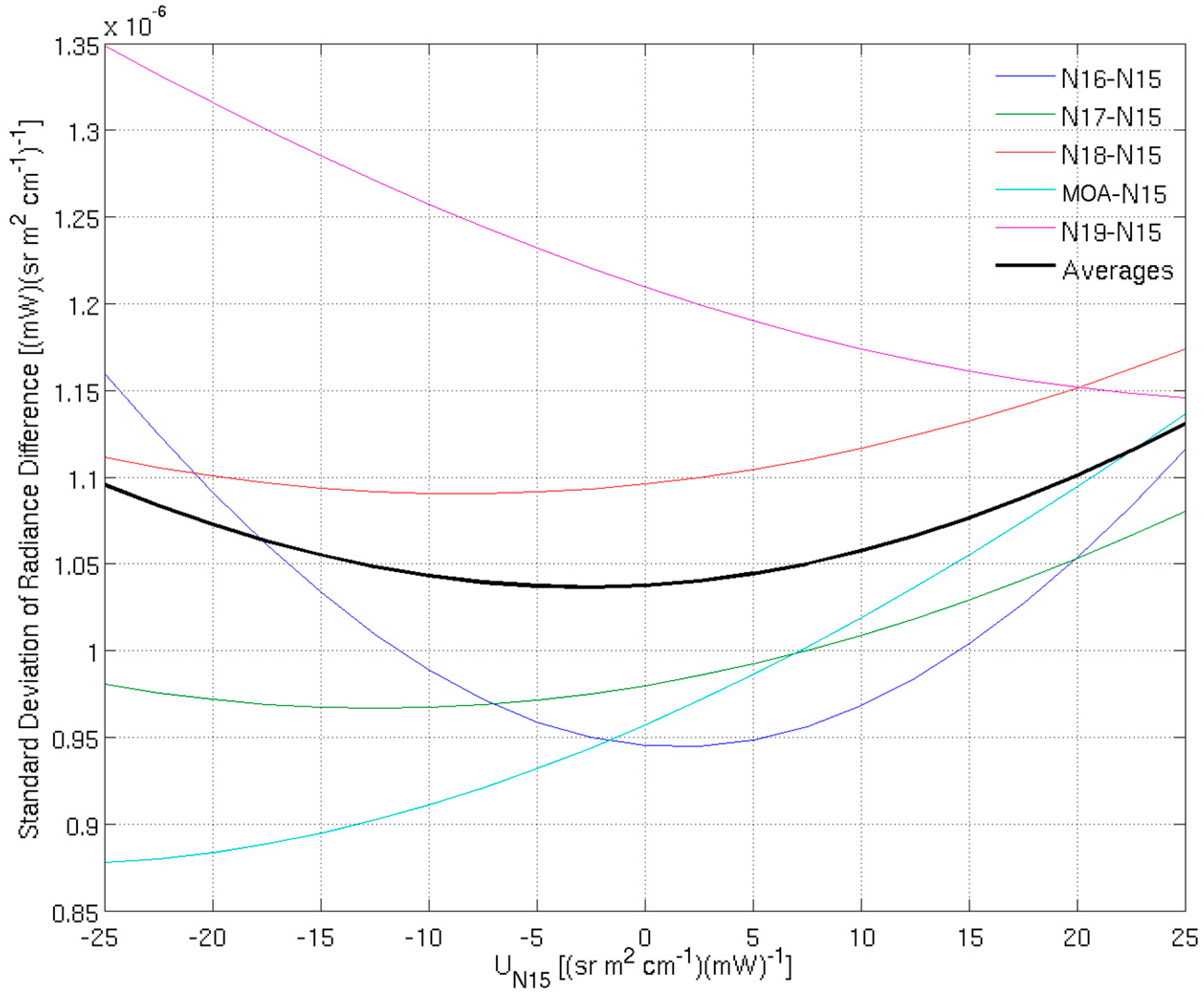
The iterative adjustment of μ N 15 is illustrated in Figure 5. By setting μ N 15 from −25 to 25 at an interval of 2.5 (sr m2 cm−1)(mW)−1, δ R j and μ j can be calculated, as described in step 4 above. Then, a set of level 1c radiances over the tropical ocean is generated, and compared with that of NOAA-15. Each satellite pair would reach minimum an STD of ΔTb, but the minimum average STD of ΔTb is selected.
The optimal μ and δ R are given in Table 5 after further corrections and modifications, as detailed in the next section.

2.3. Other Satellite Specific Corrections

After the warm target contamination bias is removed through the iterative process, two channels, 50.3 GHz on NOAA-16 and 89 GHz on NOAA-15, still exhibit some issues that need further attention before a final FCDR data set can be generated, as detailed in the following sections.

2.3.1. Slope Correction on 50.3 GHz, NOAA-16

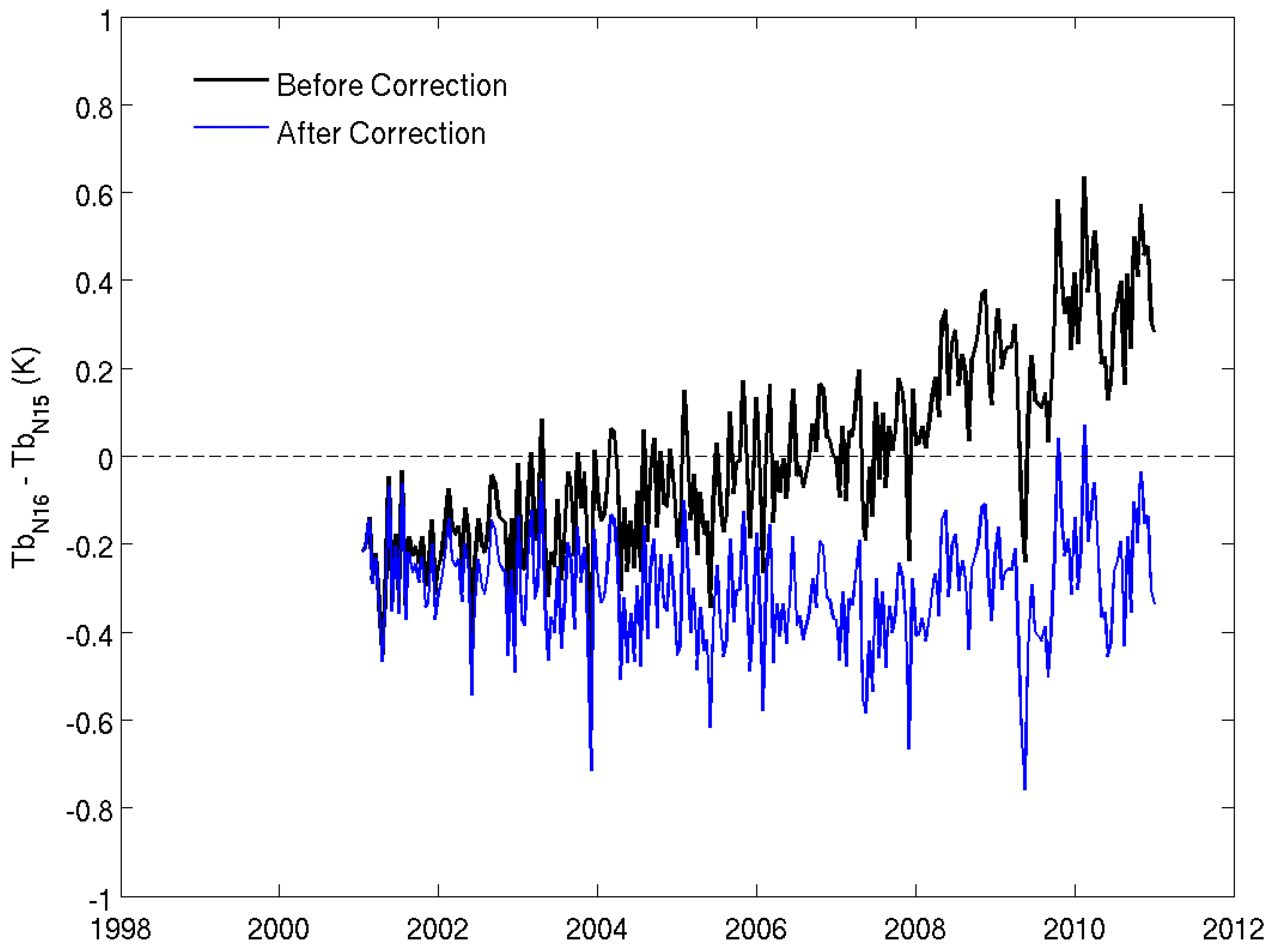
Compared to the tropical ocean mean TB of the 50.3 GHz from NOAA-15, NOAA-16 exhibits a clear upward trend of 0.06 K per year (Figure 6). This type of trend does not appear in any other satellite pairs. Apparently, this trend can only be explained by an unidentified sensor bias drift.
NOAA-16 sounding channels also show similar bias drift, as reported in References [19,22]. In Reference [22], the entire record of NOAA-16 is excluded in the time series due to the bias drift, while in Reference [19] this bias drift is corrected using the following equation:
δ R = δ R 0 + κ ( t t 0 )
where δ R 0 is a constant offset, κ is the rate of changes in the offset, t is time and t 0 is a reference time. This study utilized Equation (9) to remove the bias drift, and set t 0 to the NOAA-16 launch time. The corrected result is shown as the blue curve in Figure 6.

2.3.2. Possible Frequency Shift in 89 GHz, NOAA-15

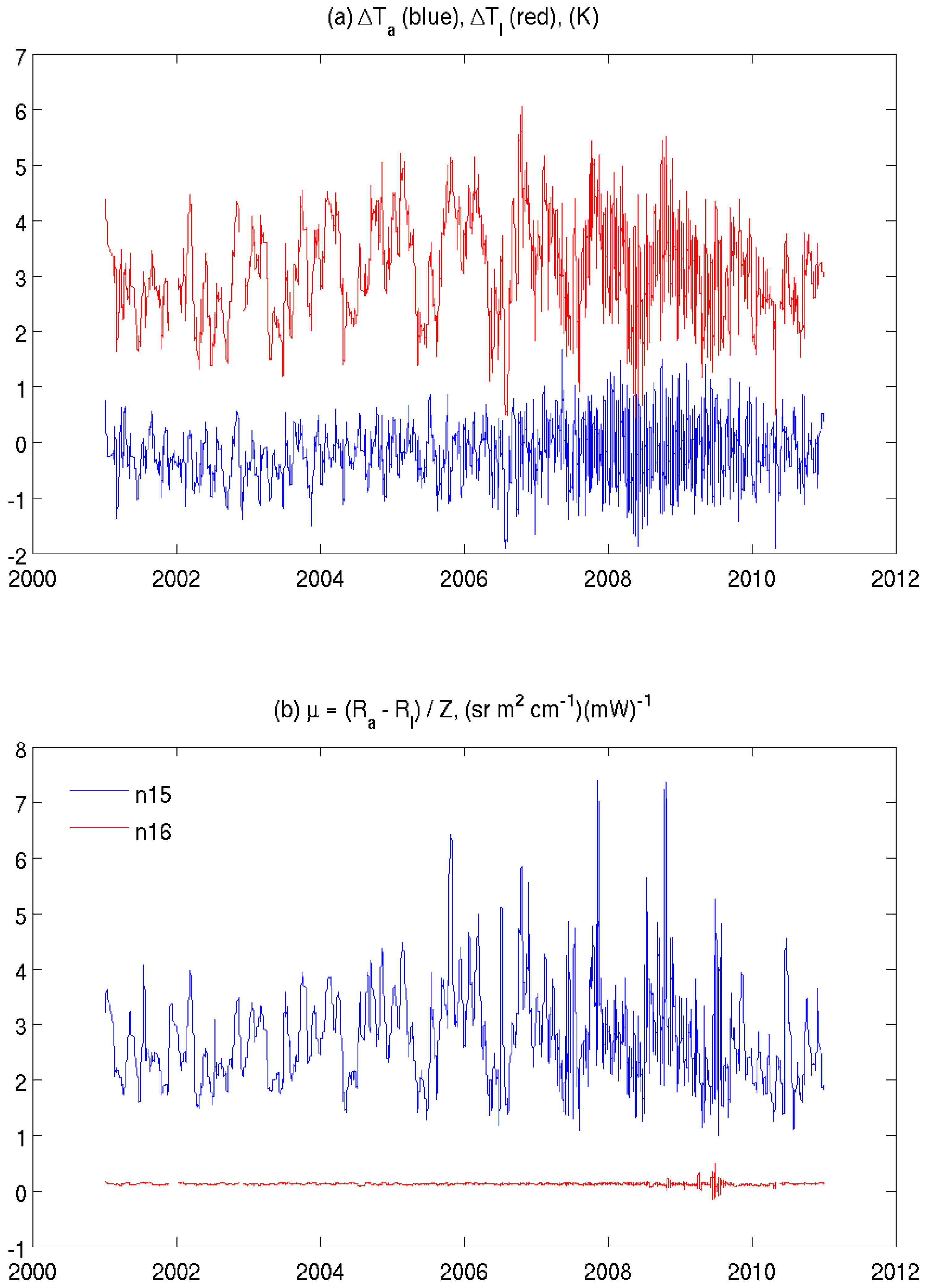
The sequential adjusting process described in Section 2.2.2 failed when applied to the 89 GHz channel on NOAA-15, as no optimal μ and δ R combination could be found to form a reasonable time series. Figure 7a shows the inter-satellite difference on the antenna temperature T a and the linear component T l from the SNO observations. Even though the difference of T a is generally around zero, the T l difference is around 3 K, and displays a well-defined seasonal variation. It is expected that their nonlinear difference would display a similar variation pattern. Figure 7b further shows the nonlinear coefficient, μ , derived from Equation (1). μ of NOAA-16 89 GHz channel is nearly a constant at around 0.1, while that of NOAA-15 89 GHz is around 3. The latter also displays a distinctive variation, which is apparently compensating for the TB difference in Figure 7a. Though not shown, μ of 89 GHz of other satellites are approximately constant, which matches the IMICA assumption of the fixed optimal μ .
Figure 7a,b show that a constant optimal μ for the 89 GHz of NOAA-15 will only result in a varied Δ T a time series similar to the red curve in Figure 7a. It means that the error in this channel cannot be corrected using IMICA. In addition, Zou and Wang stated that “Radiance biases caused by the frequency errors may mix with the nonlinear calibration errors” [19]. These observations led to our postulation that the bias arrives from an erroneous central frequency or frequency shift.
To verify this assumption and determine the magnitude of the frequency shift, we examined the change of the standard deviation of Δ Tb by adjusting the frequency shift d f , where Δ Tb is the TB difference and is defined as a function of the difference between the SNO pair and simulated TBs:
Δ T b = T b ( N 15 ) Δ T b s ( N 15 , d f ) T b ( N 16 ) = [ T b ( N 15 ) T b s ( N 15 , f m + d f ) ] + [ T b s ( N 15 , f m ) T b ( N 16 ) ]
where f m is the nominal central frequency of 89 GHz channel of NOAA-15. Following both References [19,34], the assumption of this scheme is that the minimum standard deviation of Δ T b corresponds to the value of the frequency shift. To achieve this, the global SNO pairs of NOAA-15 and NOAA-16, which occurred in August 2008, as shown in Figure 1a, were adopted as the basic comparison data set. The data is further restricted to ocean observations between 30°S and 30°N to make the simulation more reliable, as this channel is sensitive to surface conditions. Following References [18,19], CRTM [35] is selected as the radiative transfer model, and the ERA-Interim [16] as the model input. Different experimental frequencies, centered at 89 GHz on NOAA-15, were examined in the CRTM simulations with the frequency shift, df. The shift is relative to the prelaunch measurement and range from −1.5 GHz to 1.5 GHz with an interval of 25 MHz.
The comparison between the SNO observation and simulation is shown in Figure 8. The minimum standard deviation of Δ Tb (STD) was achieved between −350~−325 MHz, though the change with frequency shift was small. An additional test was carried out using the ocean emissivity, calculated using the radiative transfer model developed by the Remote Sensing System (RSS) [36]. However, the result concerning the frequency shift remains the same.
Figure 8 reveals that STD is rather insensitive to frequency shifts with a 0.03K change corresponding to about a 1.8 GHz shift. The result shows that frequency shift cannot explain the large STD, and thus our hypothesis is not valid. The root cause of the variable coefficient μ of the NOAA-15 89 GHz channel (Figure 7b) remains unclear, which may leave room for future research. For this reason, a frequency correction is not applied to this channel in the AMSU-A FCDR.
Since no optimal μ and δ R combination could be found for the 89 GHz channel of NOAA-15 AMSU-A, NOAA-16 was used as the reference satellite for this channel in the iterative approach described in Section 2.2.2.

3. Results

Table 5 lists a series of coefficients, μ , δ R 0 , and κ , which are obtained by using the approaches described in Section 2.2 and Section 2.3. Since NOAA-15 is the reference satellite for Channels 1~3, their corresponding δ R 0 ’s are set to zero, so is δ R 0 for Channel 15 of NOAA-16. The coefficients μ and δ R 0 for Channel 15 of NOAA-15 were zero because the corrections shown by Equations (5) and (9) were not applied to this channel. Most values of μ were within the range of [−4, 4], except Channel 1 of NOAA-16 and NOAA-17, which was around −7 and indicates a strong non-linearity. In general, the offsets δ R 0 of Channels 1 and 2 were on the order of 10−7 (mW)(sr m2 cm−1)−1, corresponding to ΔTb on the order of 0.02 and 0.013 K, respectively, and δ R 0 of Channels 3 and 15 were on the order of 10−6 (mW)(sr m2 cm−1)−1, corresponding to ΔTb on the order of 0.045 and 0.019 K, respectively. The exceptions were Channels 1 and 3 of NOAA-18, as both were one order of magnitude higher than the other satellites. As indicated in Section 2.3.1, only Channel 3 of NOAA-16 suffered from bias drift with a non-zero κ .

3.1. Fundamental CDR

The Fundamental CDR (FCDR) was obtained by applying geolocation correction [17], asymmetry correction [18], and inter-satellite calibration, as described in Section 2.2 and Section 2.3. The impacts of the former two corrections have been documented in the corresponding papers [17,18]. This study investigates the impact of the inter-satellite calibration.
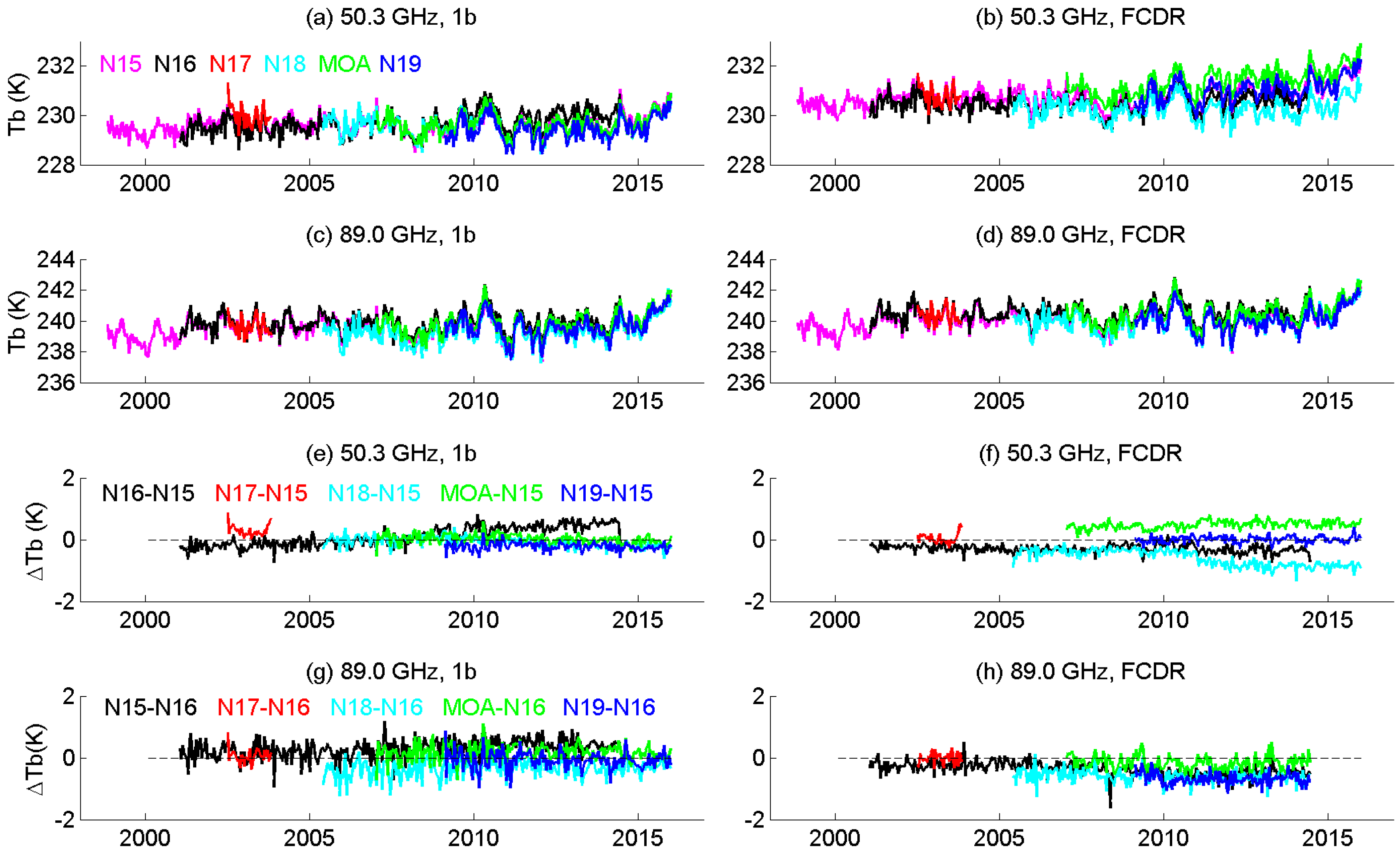
To compare the time series performance before and after inter-satellite calibration, we extracted the TB time series on the level 1b data before inter-satellite calibration and newly corrected FCDR from satellite launch time to 2015, over tropical oceans between 30°S and 30°N. Further, to avoid the residual impact of the asymmetry correction, only nadir pixels (e.g., AMSU-A beam positions 15 and 16) were selected. As seen in Figure 9a–d and Figure 10a–d, the level 1b data before inter-satellite calibration suffered no obvious inter-satellite offsets, and the FCDR Tb time series shows similar features. However, upon closer examination carried out by subtracting the TB time series from those of the referenced satellite, (shown in Figure 9e–h and Figure 10e–h), we noticed that the ΔTb of FCDR was more constant over the entire time series, which indicated that the impact of warm target contamination had been minimized. To further confirm this, Table 6 shows a comparison of the STD of ΔTb calculated from Figure 9e–h and Figure 10e–h. As an example, the STD of Channel 1 (23.8 GHz) between NOAA-16 and NNOAA-15 was 0.374 K before correction, which decreased to 0.217 K after inter-satellite calibration. Generally, the improvement to all the channels was approximately 50%.
It is worth noting that the spurious upward trend of the 50.3 GHz Tb difference between NOAA-16 and NOAA-15 (black line in Figure 10e) has been corrected (Figure 10f). There is a 0.6 K offset between Metop-A and NOAA-15, and a −0.6 K offset between NOAA-18 and NOAA-15, as indicated in Figure 10f, which can be attributed to the following reasons: 1. In order to obtain more accurate calibration coefficients solutions ( α , β , a 0 and a 1 ) with the IMICA method, it is better to include more SNO pairs. 2. In the sequential adjusting process to obtain μ N 15 , it is better to extend the training data. In the current study, both SNO pairs and the global mean difference data are only limited to 2010 to obtain the coefficients, yet the coefficients are applied to the time series up to 2015, thus the FCDR results after 2010 are less ideal, future reprocessing may improve the performance. 3. The choice of the reference satellite. In the current study, NOAA-15 was selected as the reference satellite, mainly due to its data length. This channel from NOAA-16 contains a serious bias drift, as mentioned in Section 2.3.1; the NOAA-17 AMSU-A1 module operated for only a limited time from June 2002 to the end of October 2003 due to scan motor failure; NOAA-18 drifted for nearly 8 h during its operations more than 15 years ago. Thus, future reference satellites, which perform better in terms of drifting, should include only Metop-A and NOAA-19 as candidates. However, as the diurnal drift for NOAA-18 was large, the large differences between NOAA-18 and NOAA-15 could be due to NOAA-18 diurnal drift, and it could be unrealistic to expect to have small biases between NOAA-18 and NOAA-15. However, the biases between MetOp-A and NOAA-15 might be improved when we have an SNO of up to 2015.

3.2. Thematic CDR

The suite of AMSU-A Thematic CDR (TCDR) from window channels was obtained by applying the corresponding FCDR’s to the MSPPS product suite [12]. If the FCDR was generated properly at all four AMSU-A window channels, its improvements were expected to extend into the derived products of the TCDR, including CLW, TPW, sea ice, and snow cover, etc. The derivations or regressions of all the TCDR’s were based on multiple channels of FCDR’s, and thus any erroneous correction or calibration of the FCDR’s would be inherited and magnified. Thus, both CDR’s need to be developed in a synergistic manner before the FCDR is finalized and this concept was adopted during various aspects of the FCDR development, including the geolocation and scan bias corrections. More detailed aspects of the performance of TCDR (i.e., comparisons with in-situ data, spatial analysis of seasonal to annual climate variations, etc.) will be investigated in ongoing research. Here, we only show the product consistency resulting from the inter-satellite calibration.
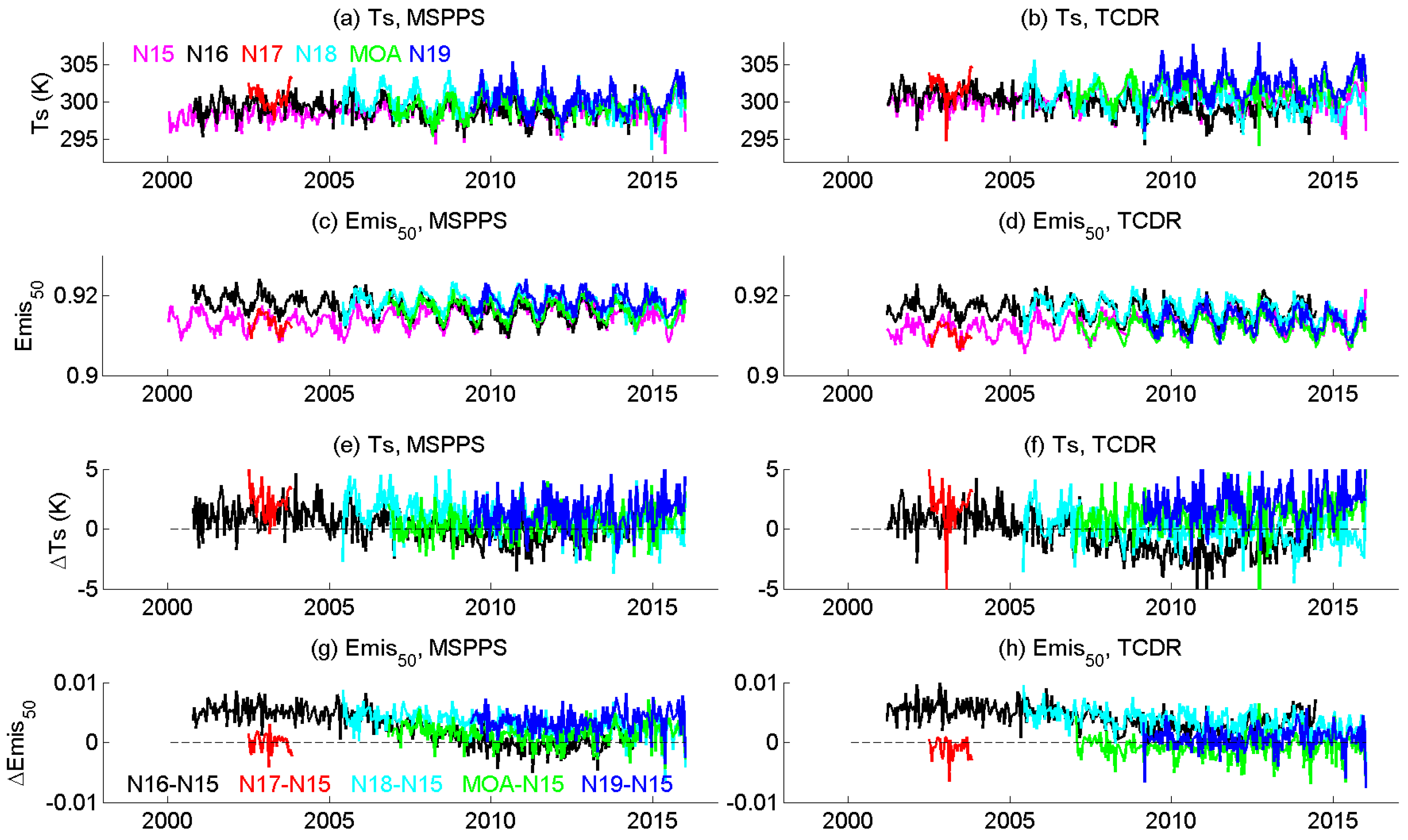
Figure 11 shows the time series of the MSPPS and TCDR’s of NOAA-15 for two ocean products, TPW and CLW, over tropical ocean between 30°S and 30°N. Only their nadir retrievals are shown to further isolate the impact of the inter-satellite corrections. Figure 12 shows similar comparison of two land products, land surface temperature (Ts), and land surface emissivity of 50.3 GHz (Emis50), over tropical land.
From Figure 11a, it is noticeable that the TPW before inter-satellite calibration displays a wet bias relative to NOAA-15, which is more clearly shown in Figure 11e, where positive values are seen. The wet bias of TPW was corrected by the TCDR, as shown in Figure 11b,f, with the overall difference being closer to zero. Similarly, the TCDR CLW series displays a better agreement among the six satellites than that of the uncorrected CLW products.
As opposed to the ocean products, the land products display distinctive diurnal effects in both versions before and after inter-satellite calibration. Specifically, Figure 12g,h displays nearly constant offsets in 50.3 GHz emissivity for different satellite pairs. The offsets are within the range of 0.01, and agree very well with other studies [37]. It should be noted that during the entire inter-satellite calibration process, land observations were only used in the calculation of SNO coefficients ( α , β , a 0   and a 1 ), mostly in high latitudes. No land observation was used in the iterative adjusting of μ N 15 . Additionally, no diurnal correction was applied; collectively, evaluation of the land products in regions where no data was used in the adjustments further demonstrates the robustness of the FCDR’s.

4. Discussion and Conclusions

With over 15 years of observations from the AMSU-A sensor and through a series of six satellites—NOAA-15, NOAA-16, NOAA-17, NOAA-18, NOAA-19 and Metop-A—global monitoring of important parameters such as total precipitable water, cloud liquid water and land surface emissivity has been achieved and well documented in the open literature. The excellent temporal sampling by the NOAA POES constellation has provided excellent compliments to the passive microwave imagers (i.e., SSM/I, AMSR-E and TMI), thus yielding a long time series dating back to around 1998. While the scientific community took note of the huge potential of passive microwave “all weather” capability and generally stable radiometric measurements to generate climate data sets in support of both national and international programs, the data sets contain deficiencies that prevent them from being classified as a true CDR, which is provided with “sufficient length, consistency, and continuity” [1]. This is mainly due to the lack of routinely updated satellite calibration information and inter-satellite calibrations that are not factored into the data processing, and which are primarily driven by the main purpose of these measurements (e.g., NWP model assimilation and derived products to support weather forecasts). Additionally, resource limitations and a lack of a true climate “requirement” within the satellite programs at NOAA have prohibited any sort of routine reprocessing as part of its core satellite operations. This gap has been bridged for AMSU-A window channels of 23.8, 31.4, 50.3 and 89.0 GHz, with the introduction of the inter-satellite calibration, after the application of geolocation [17] and cross-scan bias corrections [18]. As a result, the FCDR and TCDR time series from 1998 to 2015 have been generated and utilized to test the effectiveness of the calibration.
The Integrated Microwave Inter-Calibration Approach (IMICA) approach, which was developed for the inter-satellite calibration of AMSU-A sounding channels, was adopted in this study for the AMSU-A window channels. To minimize the impact of surface heterogeneity on the window channel observations, the appropriate standard deviation thresholds have been identified through sensitivity tests of various factors to restrict Simultaneous Nadir Overpass (SNO) data.
One critical element of the IMICA approach is how to select the proper reference satellite for each channel. It is desirable that the channel on the reference satellite has a long enough time span, and is free of, or at least suffers from few, error sources such as bias drift, frequency shift, etc. In considering the length of the record, NOAA-15 could be the best candidate as a reference satellite. Yet, when error sources are taken into account, Channel 15 (89 GHz) on NOAA-15 is not ideal due to a significant varying non-linear coefficient μ , as mentioned in Section 2.3.2. The selection of the reference satellite for Channel 3 (50.3 GHz channel) is not ideal either, as discussed in Section 3.1. Further, since NOAA-15 was launched in 1998 and is the oldest satellite carrying AMSU-A, there are some concerns over its orbital and radiometric stabilities in recent years. It is recommended that ensuing studies utilize a newer satellite, e.g., Metop-A, as the reference satellite for the years beyond 2015, while still adopting the same inter-calibration techniques. In the future, the selection of the reference channel/satellite may be improved by introducing other techniques, such as the two-sample Allan deviation to an international standard (SI) traceable noise characterization [38].
After applying the inter-satellite calibration, the consistency of AMSU-A window channels brightness temperatures have improved by 50%. In addition, the spurious trend in the NOAA-16 50.3 GHz channel has been removed. Though further assessment work, such as the detection of climate change, is needed before claiming the dataset “climate quality”, these improvements will ensure the quality of the TCDR that are generated from the AMSU-A data, such as the hydrological bundle CDR based on AMSU [39]. With the removal of most inter-satellite biases, the inter-calibrated AMSU-A radiances (FCDR’s) are expected to improve the related NWP reanalysis and other applications with regard to consistency and accuracy. Similar calibrations can be applied to measurements from more recent sensors, such as Metop-B and S-NPP ATMS. Another set of TCDR can also be generated by utilizing the operational MiRS system. In summary, this study is a critical step towards the development of a set of fundamental and thematic CDRs for hydrological and meteorological applications, and the data sets, in turn, provide a beneficial contribution to a wider CDR community [40].

Author Contributions

All authors contributed significantly to this manuscript. Specific contributions include Data Collection, W.Y. and H.M.; Data Analysis, W.Y. and Y.C.; Methodology, W.Y., H.M. and R.R.F.; Project Management, H.M. and R.R.F.; Manuscript Preparation, W.Y., H.M. and R.R.F. All authors have read and agreed to the published version of the manuscript.

Funding

This research was funded by NOAA/NCEI CDR program through grant NA09NES4400006 (Cooperative Institute for Climate and Satellites -CICS) at the University of Maryland, Earth System Science Interdisciplinary Center (ESSIC).

Acknowledgments

The authors would like to thank Cheng-zhi Zou for fruitful discussions and guidance in this study. Three anonymous reviewers are thanked for their constructive comments and suggestions. The views, opinions, and findings contained in this report are those of the authors and should not be construed as an official National Oceanic and Atmospheric Administration or U.S. Government position, policy, or decision.

Conflicts of Interest

The authors declare no conflict of interest.

References

  1. National Research Council. Climate Data Records from Environmental Satellites; National Research Council of the National Academies: Washington, DC, USA, 2004; p. 150.
  2. Goldberg, M.; Ohring, G.; Butler, J.; Cao, C.; Datla, R.; Doelling, D.; Gärtner, V.; Hewison, T.; Iacovazzi, B.; Kim, D.; et al. The global space-based inter-calibration system. Bull. Am. Meteorol. Soc. 2011, 92, 467–475. [Google Scholar] [CrossRef]
  3. Hewison, T.J.; Wu, X.; Yu, F.; Tahara, Y.; Koenig, M. GSICS Inter-Calibration of Infrared Channels of Geostationary Imagers using Metop/IASI. IEEE Trans. Geosci. Remote Sens. 2013, 51, 1160–1170. [Google Scholar] [CrossRef]
  4. Chander, G.; Hewison, T.J.; Fox, N.; Wu, X.; Xiong, X.; Blackwell, W.J. Overview of intercalibration of satellite instruments. IEEE Trans. Geosci. Remote Sens. 2013, 51, 1056–1080. [Google Scholar] [CrossRef]
  5. Iacovazzi, R.A., Jr.; Cao, C.Y. Reducing uncertainties of SNO-estimated inter-satellite AMSU-A brightness temperature biases for surface-sensitive channels. J. Atmos. Ocean. Technol. 2008, 25, 1048–1054. [Google Scholar] [CrossRef]
  6. Yang, S.; Weng, F.; Yan, B.; Sun, N.; Goldberg, M. Special Sensor Microwave Imager (SSM/I) intersonsor calibration using s simultaneous conical overpass technique. J. Appl. Meteorol. Climatol. 2011, 50, 77–95. [Google Scholar] [CrossRef]
  7. Ruf, C.S. Detection of calibration drifts in spaceborne microwave radiometers using a vicarious cold reference. IEEE Trans. Geosci. Remote Sens. 2000, 38, 44–52. [Google Scholar] [CrossRef] [Green Version]
  8. Brown, S.T.; Ruf, C.S. Determination of an Amazon hot reference target for the on-orbit calibration of microwave radiometers. J. Atmos. Ocean. Technol. 2005, 22, 1340–1352. [Google Scholar] [CrossRef] [Green Version]
  9. Wilheit, T.; Berg, W.; Jones, L.; Kroodsma, R.; McKague, D.; Ruf, C.; Sapiano, M. A consensus calibration based on TMI and WindSat. In Proceedings of the 2011 IEEE International Geoscience and Remote Sensing Symposium, Vancouver, BC, Canada, 24–29 July 2011; pp. 2641–2644. [Google Scholar]
  10. Sapiano, M.R.P.; Berg, W.K.; McKague, D.S.; Kummerow, C.D. Toward an intercalibrated fundamental climate data record of the SSM/I sensors. IEEE Trans. Geosci. Remote Sens. 2013, 51, 1492–1503. [Google Scholar] [CrossRef]
  11. Cardinali, C. Data Assimilation: Observation Impact on the Short Range Forecast. ECMWF Lecture Notes. Available online: https://software.ecmwf.int/wiki/download/attachments/31064618/ObservationImpactForecast.pdf (accessed on 9 September 2020).
  12. Ferraro, R.R.; Weng, F.; Grody, N.; Zhao, L.; Meng, H.; Kongoli, C.; Pellegrino, P.; Qiu, S.; Dean, C. NOAA operational hydrological products derived from the AMSU. IEEE Trans. Geosci. Remote Sens. 2005, 43, 1036–1049. [Google Scholar] [CrossRef]
  13. Boukabara, S.A.; Garrett, K.; Chen, W.; Iturbide-Sanchez, F.; Grassotti, C.; Kongoli, C.; Chen, R.; Liu, Q.; Yan, B.; Weng, F.; et al. MiRS: An all-weather 1DVAR satellite data assimilation and retrieval system. IEEE Trans. Geosci. Remote Sens. 2011, 49, 3249–3272. [Google Scholar] [CrossRef]
  14. Saha, S.; Moorthi, S.; Pan, H.L.; Wu, X.; Wang, J.; Nadiga, S.; Tripp, P.; Kistler, R.; Woollen, J.; Behringer, D.; et al. The NCEP climate forecast system reanalysis. Bull. Am. Meteorol. Soc. 2010, 91, 1015–1058. [Google Scholar] [CrossRef]
  15. Rienecker, M.M.; Suarez, M.J.; Gelaro, R.; Todling, R.; Bacmeister, J.; Liu, E.; Bosilovich, M.G.; Schubert, S.D.; Takacs, L.; Kim, G.K.; et al. MERRA: NASA’s modern-era retrospective analysis for research and applications. J. Clim. 2011, 24, 3624–3648. [Google Scholar] [CrossRef]
  16. Dee, D.P.; Uppala, S.M.; Simmons, A.J.; Berrisford, P.; Poli, P.; Kobayashi, S.; Andrae, U.; Balmaseda, M.A.; Balsamo, G.; Bauer, D.P.; et al. The ERA-Interim reanalysis: Configuration and performance of the data assimilation system. Q. J. R. Meteorol. Soc. 2011, 137, 553–597. [Google Scholar] [CrossRef]
  17. Moradi, I.; Meng, H.; Ferraro, R.R.; Bilanow, S. Correcting geolocation errors for microwave instruments aboard NOAA satellites. IEEE Trans. Geosci. Remote Sens. 2013, 51, 3625–3637. [Google Scholar] [CrossRef]
  18. Yang, W.; Meng, H.; Ferraro, R.R.; Moradi, I.; Devaraj, C. Cross scan asymmetry of AMSU-A window channels: Characterization, correction and verification. IEEE Trans. Geosci. Remote Sens. 2013, 51, 1514–1530. [Google Scholar] [CrossRef]
  19. Zou, C.Z.; Wang, W. Inter-satellite calibration of AMSU-A observations for weather and climate applications. J. Geophys. Res. 2011, 116, D23113. [Google Scholar] [CrossRef]
  20. Zou, C.Z.; Goldberg, M.; Cheng, Z.; Grody, N.; Sullivan, J.; Cao, C.; Tarpley, D. Recalibration of microwave sounding unit for climate studies using simultaneous nadir overpasses. J. Geophys. Res. 2006, 111, D19114. [Google Scholar] [CrossRef] [Green Version]
  21. Christy, J.R.; Spencer, R.W.; Norris, W.B.; Braswell, W.D.; Parker, D.E. Error estimates of version 5.0 of MSU-AMSU bulk atmospheric temperature. J. Atmos. Ocean. Technol. 2003, 20, 613–629. [Google Scholar] [CrossRef]
  22. Mears, C.A.; Wentz, F.J. Construction of the Remote Sensing Systems V3.2 atmospheric temperature records from the MSU and AMSU microwave sounders. J. Atmos. Ocean. Technol. 2009, 26, 1040–1056. [Google Scholar] [CrossRef] [Green Version]
  23. Robertson, F.R.; Bosilovich, M.G.; Chen, J.; Miller, T.L. The effect of satellite observing system changes on MERRA water and energy fluxes. J. Clim. 2011, 24, 5197–5217. [Google Scholar] [CrossRef] [Green Version]
  24. Cao, C.; Weinreb, M.; Xu, H. Predicting simultaneous nadir overpasses among polar-orbiting meteorological satellites for the intersatellite calibration of radiometers. J. Atmos. Ocean. Technol. 2004, 21, 537–542. [Google Scholar] [CrossRef]
  25. Cao, C.; Xu, H.; Sullivan, J.; McMillin, L.; Ciren, P.; Hou, Y.T. Inter-satellite radiance biases for the High-Resolution infrared Radiation Sounders (HIRS) on board NOAA-15, -16, and -17 from simultaneous nadir observations. J. Atmos. Ocean. Technol. 2005, 22, 381–395. [Google Scholar] [CrossRef]
  26. Wang, L.; Goldberg, M.; Wu, X.; Cao, C.; Iacovazzi, R.; Yu, F.; Li, Y. Consistency assessment of Atmospheric Infrared Sounder and Infrared Atmospheric Sounding Interferometer radiances: Double differences versus simultaneous nadir overpasses. J. Geophys. Res. 2011, 116, D11. [Google Scholar] [CrossRef]
  27. POSE Operational Status–POSE Status–OSPO. Available online: www.ospo.noaa.gov/Operations/POES/status.html (accessed on 9 September 2020).
  28. John, V.O.; Holl, G.; Buehler, S.A.; Candy, B.; Saunders, R.W.; Parker, D.E. Understanding intersatellite biases of microwave humidity sounders using global simultaneous nadir overpasses. J. Geophys. Res. 2012, 117, D02305. [Google Scholar] [CrossRef] [Green Version]
  29. Mo, T. Prelaunch calibration of the Advanced Microwave Sounding Unit-A for NOAA-K. IEEE Trans. Microw. Theory Tech. 1996, 44, 1460–1469. [Google Scholar] [CrossRef]
  30. Mo, T.; Kigawa, S. A study of lunar contamination and on-orbit performance of the NOAA-18 Advanced Microwave Sounding Unit-A. J. Geophys. Res. 2007, 112, D20124. [Google Scholar] [CrossRef]
  31. Mo, T. AMSU-A antenna pattern corrections. IEEE Trans. Geosci. Remote Sens. 1999, 37, 103–112. [Google Scholar]
  32. Zou, C.Z.; Gao, M.; Goldberg, M. Error structure and atmospheric temperature trends in observations from the Microwave sounding Unit. J. Clim. 2009, 22, 1661–1681. [Google Scholar] [CrossRef] [Green Version]
  33. Zou, C.Z.; Wang, W. Stability of the MSU-derived atmospheric temperature trend. J. Atmos. Ocean. Technol. 2010, 27, 1960–1971. [Google Scholar] [CrossRef]
  34. Lu, Q.; Bell, W. Characterizing Channel Center Frequencies in AMSU-A and MSU Microwave Sounding Instruments. J. Atmos. Ocean. Technol. 2014, 31, 1713–1732. [Google Scholar] [CrossRef] [Green Version]
  35. Han, Y.; Van Delst, P.; Liu, Q.; Weng, F.; Yan, B.; Treadon, R.; Derber, J. JCSDA Community Radiative Transfer Model (CRTM)—Version 1; NOAA Technical Report NESDIS 122; U.S. DOC NOAA: Washington, DC, USA, 2006.
  36. Meissner, T.; Wentz, F.J. The emissivity of the ocean surface between 6 and 90 GHz over a large range of wind speeds and earth incidence angles. IEEE Trans. Geosci. Remote Sens. 2012, 50, 3004–3026. [Google Scholar] [CrossRef]
  37. Norouzi, H.; Rossow, W.; Temimi, M.; Prigent, C.; Azarderakhsh, M.; Boukabara, S.; Khanbilvardi, R. Using microwave brightness temperature diurnal cycle to improve emissivity retrievals over land. Remote Sens. Environ. 2012, 123, 470–482. [Google Scholar] [CrossRef] [Green Version]
  38. Tian, M.; Zou, X.; Weng, F. Use of Allan Deviation for characterizing satellite microwave sounder noise equivalent differential temperature (NEDT). IEEE Geosci. Remote Sens. Lett. 2015, 12, 2477–2480. [Google Scholar] [CrossRef]
  39. Ferraro, R.R.; Nelson, B.R.; Smith, T.; Prat, O.P. The AMSU-based hydrological bundle climate data record—Description and comparison with other data sets. Remote Sens. 2018, 10, 1640. [Google Scholar] [CrossRef] [Green Version]
  40. Yang, W.; John, V.O.; Zhao, X.; Lu, H.; Knapp, K.R. Satellite Climate Data Records: Development, Applications, and Societal Benefits. Remote Sens. 2016, 8, 331. [Google Scholar] [CrossRef] [Green Version]
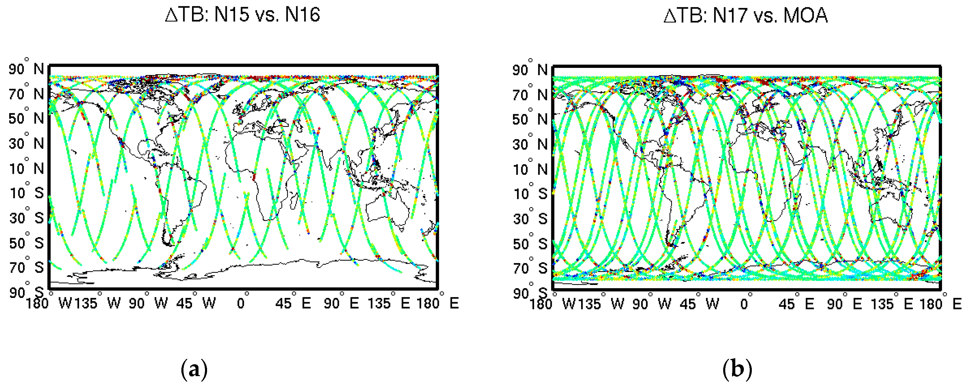
Figure 1. Geographical distribution of 23.8 GHz brightness temperature difference where global SNOs occur between (a) N15 and N16, (b) N17 and MOA, (c) N18 and N19. (d) shows normalized histogram of the brightness temperature difference of the three pairs. The SNO is defined as observation from two satellites with time difference within 50 s, and distance within 50 km (NOAA-18 vs. NOAA-19 pair needs larger distance as 75 km). The color bar of ΔTB and associated normalized histogram of these three cases are illustrated in the lower right panel. In the labels of the figures, N15 is short for NOAA-15, and MOA is short for MetOP-A.
Remotesensing 12 02988 g001aRemotesensing 12 02988 g001b
Figure 2. Smoothed brightness temperature differences of SNO pairs between AMSU-A onboard N15 with N16 through N19 and MetOP-A, from their operational time till the end of 2010 for (a) 23.8, (b) 31.4, (c) 50.3 and (d) 89 GHz. The typical uncertainty on the difference is about the same order of the difference. (e) Shows number of SNO matchups between N15 and other satellites, in the logarithm scale.
Remotesensing 12 02988 g002aRemotesensing 12 02988 g002b
Figure 3. Scatter plot between NOAA-15 and NOAA-16 SNO brightness temperature for 23.8 GHz channel under various ranges of NEΔT, to test the brightness temperature contrast (BTC) threshold.
Remotesensing 12 02988 g003
Figure 4. Warm target temperature variation between AMSU-A onboard N15 and N16, from their operational time through 2010 for (a) 23.8, (b) 31.4, (c) 50.3, and (d) 89 GHz. Note: the only observations during their SNO period are shown to decrease the sampling.
Remotesensing 12 02988 g004
Figure 5. Iterative search for μ N 15 of 23.8 GHz channel. The average line is the major criterion to select the optimal μ N 15 .
Remotesensing 12 02988 g005
Figure 6. The tropical ocean mean brightness temperature time series of 50.3 GHz channel onboard NOAA-16 versus NOAA-15 displays an upper trend (black curve), a new time series (blue curve) is formed through removing the trend line.
Remotesensing 12 02988 g006
Figure 7. Characterization of the nonlinearity of 89 GHz channel of NOAA-15 from SNO pairs of NOAA-15 and 16. (a) T a and T l difference between NOAA-15 and 16. (b) μ of NOAA-15 and -16, calculated from Equation (1).
Remotesensing 12 02988 g007
Figure 8. Amplitude of the standard deviation of Δ Tb (Equation (10)) using SNO pairs over the tropical ocean versus the 89 GHz channel of NOAA-15 frequency shift, d f .
Remotesensing 12 02988 g008
Figure 9. Tropical ocean mean Tb (ad) and ΔTb (eh) for 23.8 and 30.4 GHz channels. Left panels display the values of 1b before inter-satellite calibration, while the right panels are FCDRs after inter-satellite calibration.
Remotesensing 12 02988 g009
Figure 10. Tropical ocean mean Tb (ad) and ΔTb (eh) for 50.3 and 89.0 GHz channels. Left panels display the values of 1b before inter-satellite calibration, while the right panels are FCDRs after inter-satellite calibration.
Remotesensing 12 02988 g010
Figure 11. Retrieved tropical ocean products comparison, note different variables are used in different panels. Left panels display the products produced by MSPPS from 1b before inter-satellite calibration, while right panels are TCDR after inter-satellite calibration. Time series of total precipitable water (TPW) is shown in (a,b), the difference versus N15 is shown in (e,f); time series of cloud liquid water (CLW) is shown in (c,d), the difference versus N15 is shown in (g,h).
Remotesensing 12 02988 g011
Figure 12. Retrieved tropical land products comparison, note different variables are used in different panels. Left panels display the products produced by MSPPS from 1b before inter-satellite calibration, while right panels are TCDR after inter-satellite calibration. Time series of land surface temperature (Ts) is shown in (a,b), the difference versus N15 is shown in (e,f); time series of land surface emissivity of 50.3 GHz channel (Emis50) is shown in (c,d), the difference versus N15 is shown in (g,h).
Remotesensing 12 02988 g012
Table 1. Satellite orbital parameters.
Launch DateDecommission DateAltitude (km)Period (min)Inclination (deg)Precession Rate (min/mon)
NOAA-1505/13/1998 807101.1098.51.05
NOAA-1609/21/200006/09/2014849102.0099.03.00
NOAA-1706/24/200204/10/2013810101.2098.7−4.62
NOAA-1805/20/2005 854102.1298.73.52
MetOP-A10/19/2006 817101.3698.7
NOAA-1902/06/2009 870102.1498.70.77
Table 2. Satellite central frequencies.
Central Frequency (GHz)
Channel 1Channel 2Channel 3Channel 15
NOAA-1523.80001359331.39999223850.29998804389.000016571
NOAA-1623.80001359331.39999223850.29998804389.000016571
NOAA-1723.79920415431.39966246650.29917860389.000076529
NOAA-1823.79920415431.39966246650.29917860388.999986591
MetOP-A23.79920415431.39966246650.29917860389.000076529
NOAA-1923.79920415431.39966246650.29917860389.000076529
Table 3. Overlap and interval days (in parentheses) for each satellite pairs.
NOAA-16NOAA-17NOAA-18MetOP-ANOAA-19
NOAA-151 (8.16)4.5 (104)1 (7.31)1 (31.7)1 (7.14)
NOAA-16 1 (8.44)3 (82.0)1 (11.2)2 (66.0)
NOAA-17 1 (7.66)2 (40.0)1 (7.52)
NOAA-18 1 (9.81)8 (326.0)
MetOP-A 1 (9.62)
Table 4. Correlation coefficients between ΔTB and related factors.
Correlation Coefficients23.8 GHz31.4 GHz50.3 GHz89 GHz
(NOBS)(53,531)(53,531)(53,534)(53,506)
Distance0.190.180.150.18
S1 * BTC0.530.530.470.43
S2 * BTC0.550.550.50.44
Time Difference−0.01−0.01−0.01−0.01
* S1 and S2 indicate the two satellites in a SNO pair, e.g., in the pair NOAA-15 vs. NOAA-16, S1 refers to NOAA-15 and S2 refers to NOAA-16.
Table 5. Calibration coefficients for AMSU-A Channels 1–3 and 15 a.
Ch #NOAA-15NOAA-16NOAA 17NOAA-18MetOP ANOAA-19
μ 1−3.00870−7.25050−7.22996−0.88067−0.980530.10012
2−1.05123−3.35409−2.847011.51212−1.28394−2.30045
3−2.37781−2.31567−2.20964−2.09040−2.62705−1.28555
150−0.16528−0.257430.366180.214460.25637
δ R 0 10−3.874 × 10 7 −5.459 × 10 7 1.675 × 10 6 −4.635 × 10 7 −3.931 × 10 7
20−6.009 × 10 7 −6.199 × 10 7 −2.792 × 10 7 −5.270 × 10 7 −4.772 × 10 7
30−1.496 × 10 6 −1.750 × 10 6 1.051 × 10 5 −5.953 × 10 6 −4.744 × 10 6
1500−7.220 × 10 7 −2.927 × 10 6 −6.715 × 10 6 −2.017 × 10 6
κ 1000000
2000000
301.448 ×   10 6 0000
15000000
a Units for μ , δ R 0 and κ are (sr m2 cm−1)(mW)−1, (mW)(sr m2 cm−1)−1, and (mW)(sr m2 cm−1)−1yr−1.
Table 6. Standard deviation of Tb difference of specified channels and satellite pairs, before and after inter-satellite calibration a.
BeforeAfter
Channel1231512315
N16-N150.3740.2630.2670.3150.2170.1930.1260.227
N17-N150.2850.2170.1910.2250.1910.1910.1710.132
N18-N150.3860.2590.1680.3370.2390.1970.130.242
M02-N150.370.3840.1670.3280.2150.2070.1080.227
N19-N150.4240.2760.1740.3740.2630.1870.1150.208
a Unit is K. “Before” corresponds to the uncorrected L1b data and “After” refers to the FCDR.