Article

Research on Resource Allocation Method of Space Information Networks Based on Deep Reinforcement Learning

Science and Technology on Complex Electronic System Simulation Laboratory, Space Engineering University, Beijing 101416, China
*
Author to whom correspondence should be addressed.
Remote Sens. 2019, 11(4), 448; https://doi.org/10.3390/rs11040448
Submission received: 16 January 2019 / Revised: 16 February 2019 / Accepted: 18 February 2019 / Published: 21 February 2019

Abstract

:
The space information networks (SIN) have a series of characteristics, such as strong heterogeneity, multiple types of resources, and difficulty in management. Aiming at the problem of resource allocation in SIN, this paper firstly establishes a hierarchical and domain-controlled SIN architecture based on software-defined networking (SDN). On this basis, the transmission, caching, and computing resources of the whole network are managed uniformly. The Asynchronous Advantage Actor-Critic (A3C) algorithm in deep reinforcement learning is introduced to model the process of resource allocation. The simulation results show that the proposed scheme can effectively improve the expected benefits of unit resources and improve the resource utilization efficiency of the SIN.

1. Introduction

At present, with the gradual deepening of space science exploration and the continuous development of space information technology, the construction of space information systems presents a state of explosive development. However, the construction of all kinds of spatial information systems is still separate, forming a situation of repeated construction and “chimney-like development”. Various navigation, communication, remote-sensing, and other satellites occupy a large amount of orbital resources. When a single satellite system completes a given task, it will have more idle states, resulting in a waste of space resources [1]. The proposal of the space information network (SIN) provides a solution to the above problems. The SIN became a research hotspot in the global field [2].
The SIN is a network system that acquires, transmits, and processes spatial information in real time on various space platforms (such as synchronous satellites or mid-orbit satellites, stratospheric balloons, and manned or unmanned aerial vehicles) [3]. Compared with the ground network, the SIN plays an irreplaceable role in earth observation, emergency communication, air transportation, space TT&C, and the expansion of national strategic interests [4]. Compared with the traditional satellite network, the SIN has a series of characteristics such as complex structure, dynamic topology change, large cross-domain spatial scale, and so on. Therefore, we need to build an efficient SIN architecture to realize the effective allocation and management of multi-dimensional resources in the SIN, which is of great significance for the construction of the SIN [5].
Software-defined networking (SDN) is a new network architecture with data forwarding which is control-separated and software-programmable. SDN adopts a centralized control surface and a distributed forwarding surface. The control plane uses the developed control and forwarding communication interface to centralize the control of network devices on the forwarding plane, while providing flexible programmable capabilities [6]. The core idea of SDN is applied to the SIN. The data plane and control plane of satellite are separated, such that the satellite mainly implements simple forwarding and hardware configuration functions, thus solving the disadvantages of complex design and high cost of satellite nodes. The resources of transmission, caching, and computing of the whole network are allocated by the controller, which can not only lighten the burden of satellite nodes, but also benefit the unified management of the whole network [7,8].
Deep reinforcement learning is a new research hotspot at present. It combines the perception ability of deep learning with the decision-making ability of reinforcement learning, and can realize direct control from original input to output. The Asynchronous Advantage Actor-Critic (A3C) algorithm is a deep reinforcement learning algorithm proposed by DeepMind in 2015 [9]. The A3C algorithm evaluates the output action. On the basis of using the Actor-Critic framework, the idea of asynchronous training is introduced, which effectively improves the training efficiency and reduces the training time [10]. The application of the A3C algorithm in the SIN can effectively solve the problem of dynamic allocation of the SIN resources, thereby improving the utilization efficiency of the SIN resources.
Current research on the SIN mainly focuses on architecture design and the routing algorithm. Relevant research institutes and scholars proposed to apply SDN technology to the construction of the SIN, but there is a lack of specific multi-dimensional resource allocation methods. The main features of this paper are as follows:
  • Based on the core idea of SDN, a hierarchical and domain-controlled SIN architecture is established. The overall network architecture and network control architecture are designed.
  • On the basis of the SDN-based SIN architecture, the transmission resources, caching resources, and computing resources in the SIN are unified. Among them, the transmission resource depends on the coverage time of low Earth orbit (LEO) satellite to users, the transmission state of geostationary orbit (GEO) data relay satellite, and the communication link state.
  • The dynamic allocation of multi-dimensional resources in the SIN is modeled mathematically. A SIN resource allocation method based on the A3C algorithm is proposed.
  • The expected benefits of unit resources under different conditions are simulated and analyzed. The simulation results show that the proposed scheme of unified management of transmission resources, caching resources, and computing resources has better expected benefits, and can effectively improve the efficiency of the SIN resources.
The rest of this article is arranged as follows: Section 2 analyzes the related research of the SIN and SDN-based SIN. Section 3 proposes an SDN-based SIN architecture and builds the system model. In the Section 4, the dynamic allocation of multi-dimensional resources in the SIN is modeled as a deep reinforcement learning process based on the algorithm of A3C. The Section 5 simulates and analyzes the scheme proposed in this paper. Section 6 summarizes and discusses the full text.

2. Related Work

2.1. Space Information Networks

The SIN is an important international scientific frontier and strategic commanding height in the world today. At present, the representative projects are the (Space Communications and Navigation (SCaN) of the National Aeronautics and Space Administration (NASA) [11], the Transformational Satellite Communication System (TSAT) of the United States (US) [12], and the Integrated Space Infrastructure for Global Communications (ISICOM) of Europe [13]. SCaN plans to divide the network system into a backbone network, access network, spacecraft intranet, and adjacent network, which can adequately meet the needs of future space communications in the United States. Based on this framework, there is no need to build a new communication infrastructure for emerging tasks, which can effectively avoid duplication of construction. TSAT was proposed by the US Department of Defense in 2002. It consists of a space segment, terminal segment, and mission operation segment. The goal of TSAT is to adapt to the transformation of communication needs of the US military, break the communication bottleneck, and provide users with a secure and high-speed communication architecture. Although the TAST project eventually stopped, its overall architecture laid the foundation for the development of SIN technology. In September 2008, the European Union adopted a Security Council resolution on “Making Future European Space Policy”, and the concept of ISICOM came into being. The ISICOM system consists of a space-based network and a terrestrial network. The goal is to establish an independent Internet Protocol (IP)-based communication network, which combines microwave and laser links to achieve broadcast services, emergency services, telemedicine, distance education services, and other services.
Through the investigation and analysis of the current research situation of the SIN, according to the way of networking, the current SIN architecture can be divided into three categories: satellite-earth network, space-based network, and space–net–Earth network. Its typical system and main characteristics are shown in Table 1 [14,15].
In conclusion, the space–net–Earth network architecture can make full use of the wide-area coverage ability and the abundant transmission and processing ability of the space-based network, and reduce the complexity and cost of the system technology; it is a more appropriate reference for the construction of the SIN.
Aiming at the resource scheduling problem of the SIN, the current research mainly focuses on the resource scheduling of the GEO data relay satellite. Adinolfi used a backtracking heuristic algorithm to solve the resource scheduling problem of the GEO data relay satellite for the European Space Station [16]. Rojanasoonthon studied the tracking and data relay satellite system (TDRSS) of the United States, and studied the scheduling problem with two visual time windows [17]. Gu analyzed the resource and task constraints in the scheduling process of the GEO data relay satellite, and established the scheduling model of the GEO data relay satellite [18]. The current research lacks research on the overall resource allocation method for different types of nodes in the SIN.

2.2. SDN-Based Space Information Networks

Based on the advantages of SDN technology, some scholars and research institutes proposed its application in the SIN. The related research is still in its infancy, mainly focusing on the research of architecture and routing algorithms. Researchers at the Centre National de la Recherche Scientifique (CNRS) and Université de Toulouse studied handover decision-making algorithms in satellite networks through SDN’s programmability [19]. Joint researchers from the Polytechnic University of Catalonia and the Greek National Research Center are exploring the introduction of SDN technology into satellite networks. SDN technology is used to improve the satellite network infrastructure, so as to improve the joint service capability of ground and satellite networks and hybrid access service capability [20]. Researchers from Hughes Network Systems Inc. of the United States directly proposed a software-defined satellite network (SDSN) architecture, and applied it to their SPACEWAY system (a new generation of broadband satellite communication system). By establishing modules and performance objects, the extended allocation of inter-satellite packet routing addresses and the resource management control in the controller were realized [21]. Reference [22] proposes a networking architecture for on-board switching systems based on SDN. SDN on-board switching system can effectively reduce the load of traditional on-board switching systems, optimize the utilization of satellite channel resources, and improve the quality of service support capability of satellite communication networks. References [23,24] analyzed the routing algorithm of SDN-based SIN.
SIN includes a large number of heterogeneous nodes such as satellites, caches, mobile edge computing (MEC) servers, and so on. The allocation of the SIN resources involves the allocation of multi-dimensional resources such as transmission, caching, and computing. It is necessary to make overall considerations to achieve the maximum effective use of the SIN resources.

3. System Model

In this section, we firstly establish an SDN-based SIN architecture. On this basis, this article takes the use of LEO communication satellites and GEO data relay satellites for information transmission as an example; the network model, satellite coverage and transmission model, communication link model, caching model, and computing model of the SIN are analyzed.

3.1. SDN-Based Space Information Network Architecture

3.1.1. Overall Networking Architecture

Based on the core idea of SDN, this paper establishes a hierarchical and domain-controlled SIN architecture, whose overall network architecture is shown in Figure 1.
From a hierarchical point of view, the SIN architecture is divided into three parts: space-based, air-based, and ground-based. The space-based network is mainly composed of satellites with different orbits, which are geostationary orbit satellites (GEO), medium orbit satellites (MEO), and low orbit satellites (LEO) from far to near. Air-based networks include stratospheric airships, balloons, manned or unmanned aerial vehicles, etc. Ground-based networks are mainly composed of gateway base stations, caches, and MEC servers, as well as space-based network controllers, space-based network controllers, ground-based network controllers, and an SIN resource management and scheduling center. Because the resource management and scheduling center of the SIN plays an important role, a backup center should be set up.
From the point of view of sub-domain, the ground-based network, space-based network, and air-based network are divided into several domains according to the region; each domain is controlled by a network controller. Among them, there are three kinds of network controllers, space-based network controllers, air-based network controllers, and ground-based network controllers, which control space-based networks, air-based networks, and ground-based networks, respectively. In order to make full use of the global coverage capability of GEO satellites and the high-speed computing capability of ground controllers, space-based network controllers are divided into space-based network controllers on the ground and space-based network controllers on the GEO satellite. Space-based network controllers on the ground are responsible for computing and storing large amounts of data and other complex functions. Space-based network controllers on the GEO satellite are responsible for collecting global views, completing simple routing storage, distributing flow tables, and other functions. Each network controller constitutes a single-domain controller, and multiple single-domain controllers are uniformly controlled by the SIN resource management and scheduling center [25].

3.1.2. Network Control Architecture

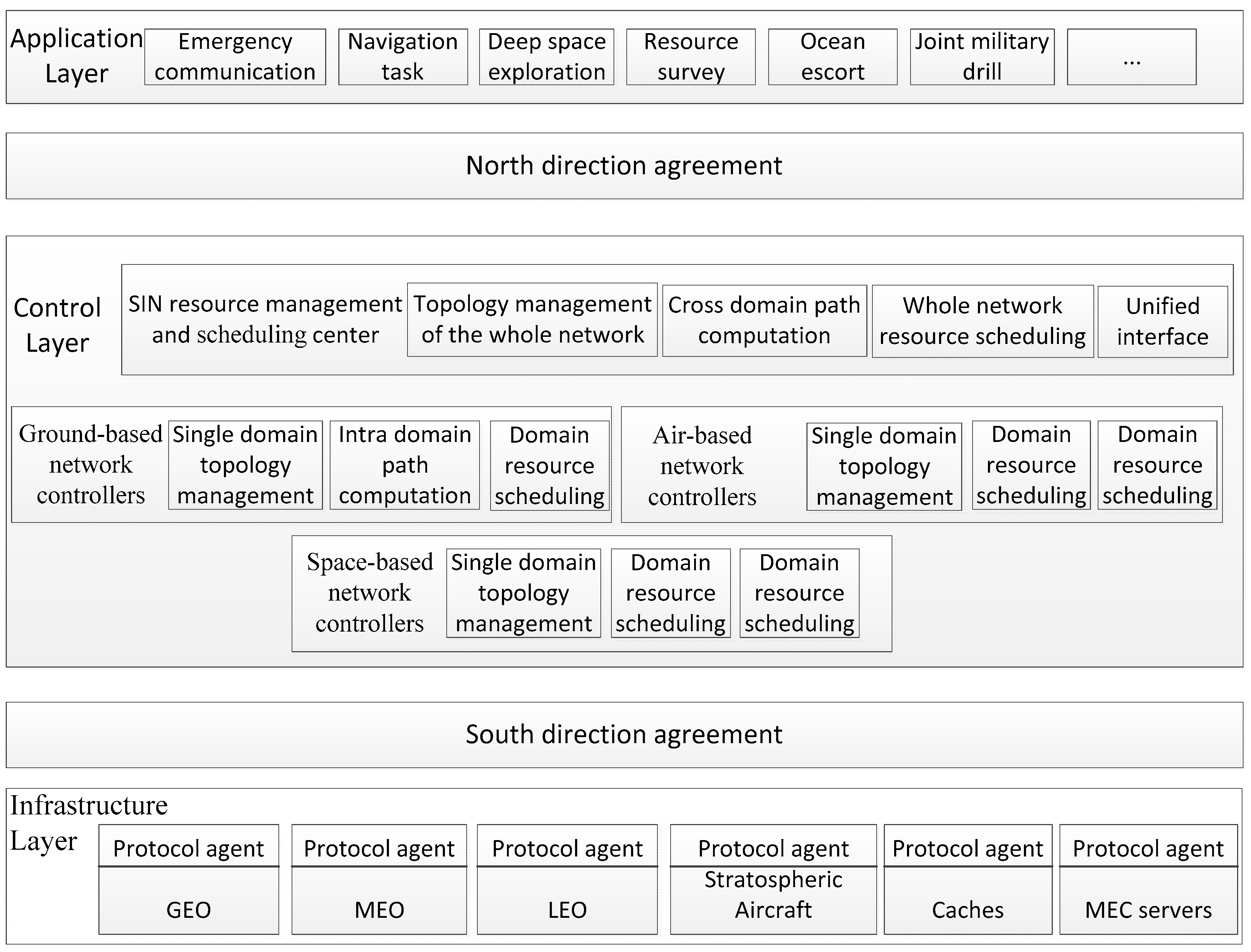
Based on the structure of SDN, the control architecture of the SIN is divided into three layers: application layer, control layer, and infrastructure layer [26]. The top layer is the application layer, which refers to a series of space tasks such as emergency communication and deep space exploration completed by the SIN. At the bottom is the infrastructure layer, which refers to satellites in different orbits, stratospheric vehicles, gateway base stations, and so on. In the middle is the control layer, which is composed of network controllers and the SIN resource management and scheduling center. The hierarchical and domain-based control structure of the SIN is shown in Figure 2.
In the control layer, the single-domain controller collects the topological information of each node in the domain. When the intra-domain traffic arrives, the single-domain controller calculates the intra-domain links, and controls the nodes by downloading the flow table, so as to realize path building and service processing. The SIN resource management and scheduling center is responsible for the control and allocation of the whole-network resources. It obtains the domain topology resources from the single-domain controller and establishes the whole-network topology. When cross-domain service arrives, it is responsible for cross-domain path calculation to realize cross-domain service transmission. In addition, due to the heterogeneity of different inter-domain networks, the SIN resource management and scheduling center is also responsible for the unification of heterogeneous device interfaces to achieve cross-domain interconnection of heterogeneous devices.
In the SIN management architecture based on SDN, north-direction agreement and south-direction agreement play an important role. North-direction agreement is a series of interfaces between application layer and control layer. There is no unified standard for its interface protocol. Therefore, the control layer provides many extensible application program interfaces (APIs) for different users in the application layer, and each API interface corresponds to a corresponding application; thus, the control architecture can implement a variety of application services. A typical south-direction agreement is OpenFlow [27], which is responsible for the interaction between the control layer and the underlying implementation switches to complete the forwarding of infrastructure layer data. In the OpenFlow protocol, an OpenFlow switch can connect multiple network controllers; however, at the same time, only one controller has control over it, and other controllers have read-only function. In the SDN-based SIN management architecture, all switches in each single domain can only be managed by its single-domain controller.

3.2. Network Model

The SIN resource management and scheduling center and the single-domain controllers realize the dispatching of various resources. This paper takes an LEO communication satellite and GEO data relay satellite as examples to analyze. Let la, lga, ca, ma, and ua represent the LEO communication satellite, GEO data relay satellite, cache device, MEC server, and user in the underlying physical resources, respectively. Let l a = { 1 , , L } , l g a = { 1 , , L g } , c a = { 1 , , C } , m a = { 1 , , M } and u a = { 1 , , U } , where L, Lg, C, M, and U represent the number of LEO satellites, GEO data relay satellites, caches, MEC servers, and users, respectively [28].

3.3. Satellite Coverage and Transmission Model

3.3.1. LEO Satellite Coverage Model

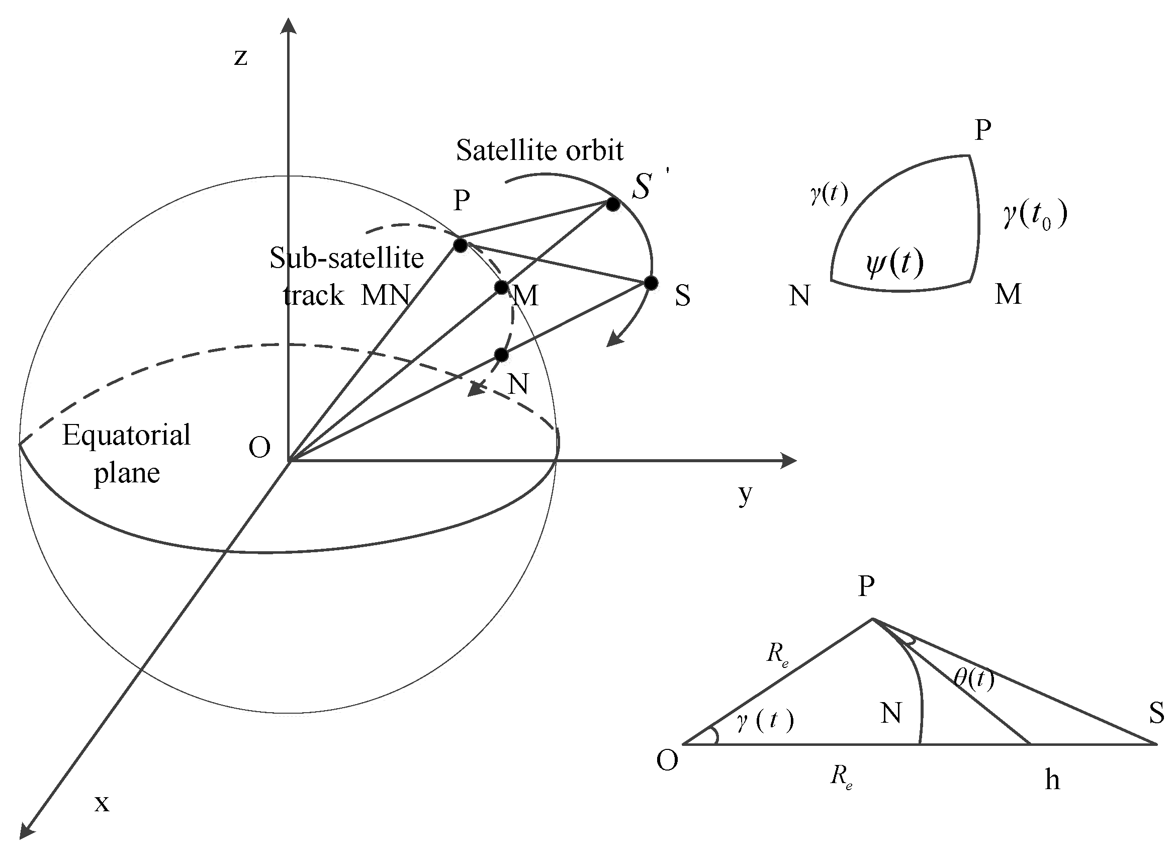
LEO satellite can only cover users in a certain time and space range to complete the transmission of information. The geometric relationship between LEO satellite and user is shown in Figure 3.
In Figure 3, O is the geocentric, R e is the earth radius, h is the LEO satellite orbit altitude, and P represents the ground user; at t 0 time, the maximum elevation of the ground user is θ max , and the LEO satellite position and the sub-satellite points are S and M. At t time, the LEO satellite position and satellite sub-satellite points are S and N. Furthermore, γ ( t 0 ) , γ ( t ) and ψ ( t ) represent the corresponding geocentric angles between P and M, P and N, and M and N, respectively. In addition, θ ( t ) represents the elevation of the ground user at time t; θ ( t ) is the minimum elevation of the ground user, and the corresponding maximum geocentric angle at time t is γ max .
According to the spherical triangle PMN and the triangle OPS shown in Figure 3, we can obtain the following:
cos γ ( t ) = cos ψ ( t ) cos γ ( t 0 ) ;
γ ( t ) = a r c   c o s ( R e R e + h cos θ ( t ) ) θ ( t ) .
The effective coverage time t c of LEO satellite to ground users is
t c = 2 ω ψ ( t ) = 2 ω a r c   c o s ( cos γ max cos γ ( t 0 ) ) ,
where ω = ω s ω e i 0 is the angular velocity of a satellite in the Earth-centered, Earth-fixed, (ECEF) coordinate system, ω s is the angular velocity of a satellite in the Earth-centered inertial (ECI) coordinate system, ω e is the angular velocity of the earth’s rotation under ECI, and i 0 is the orbital inclination angle.
Ground users are randomly distributed. We assume that the distance from the ground user to the sub-satellite point obeys a uniform distribution. Therefore, when the LEO satellite covers ground users, γ ( t 0 ) satisfies the U ( 0 γ max ) uniform distribution. The probability density function f γ ( t 0 ) ( γ ( t 0 ) ) of γ ( t 0 ) is
f γ ( t 0 ) ( γ ( t 0 ) ) = { 1 / γ max , 0 γ ( t 0 ) < γ max 0 ,   Other .
According to Equations (3) and (4), the cumulative distribution function of coverage time t c is
F T c ( t c ) = P ( 2 ω a r c   c o s ( cos γ max cos γ ( t 0 ) ) t c ) = 1 1 γ max a r c   c o s ( cos γ max / cos ω t c 2 ) , 0 < t c T m
where T m represents the maximum effective coverage time of satellite to ground users. When γ ( t 0 ) = 0, according to Equation (3), we can get
T m = max ( t c ) = 2 γ max / ω .
According to Equation (5), the probability density function of coverage time f t c ( t c ) is
f t c ( t c ) = { ω c o s g m a x t a n ( ω t c / 2 ) 2 γ max cos 2 ( ω t c / 2 ) cos 2 γ max , 0 < t c 2 γ max ω 0   Other   .
According to Equation (7), the average coverage time E ( t c ) of LEO satellite to ground users is as follows [29]:
E ( t c ) = 2 cos γ max ω γ max 0 γ max x tan x cos 2 x cos 2 γ max d x .
The elevation θ u l used between u and LEO satellite l is
θ u l = a r c   t a n ( cos Θ R e / ( R e + h ) sin Θ ) ,
where
c o s Θ = cos ( u l o l l o ) cos u l a cos l l a + sin u l a sin l l a .
In Equation (10), u l o and u l a represent the longitude and latitude of the user, respectively, while l l o and l l a represent the longitude and latitude of LEO satellite, respectively.
When the LEO satellite is flying around the equator, l l a = 0, the longitude of the user and the satellite is the same, u l o = l l o , the elevation is the maximum, and Equation (10) can be simplified into
c o s Θ = cos u l a .
Therefore, within the average coverage time E ( t c ) , the maximum θ u l max of θ u l is
θ u l max = a r c   t a n ( cos u l a R e / ( R e + h ) sin u l a ) .
To ensure that elevation increases monotonously, we set Ω as the elevation of LEO satellite from the horizon to the user. The relationship between Ω and θ u l is as follows:
Ω = { θ u l      θ u l θ u l , max 2 * θ u l , max θ u l    θ u l > θ u l , max   .
The maximum value of Ω is Ω max = 2 * θ u l , max . In this model, the smaller Ω is, the longer the LEO satellite coverage time will be. LEO satellites have more time to transmit, cache, and compute information with users. The larger Ω is, the shorter the coverage time of LEO satellite to users will be, and the less time it will take for the LEO satellite to transmit, cache, and compute information with users.
Because there are many LEO satellites in the SIN, we cannot determine which LEO satellite is connected to the user, nor can we determine the elevation of user u and satellite l at the next moment. Therefore, we set the elevation angle of user u and satellite l to the random variable Ω u l . The value range of Ω u l can be divided into Y segments: Ω 0 * Ω u l Ω 1 * , y 0 ; Ω 1 * Ω u l Ω 2 * , y 1 ; …; Ω Y 1 * Ω u l Ω u , max l , y Y 1 . Each segment conforms to a Markov chain model and has Y segments, that is, y = { y 0 , y 1 , , y Y 1 } . The elevation of user u and LEO satellite l at time t is expressed as w u l ( t ) , where t { 0 , 1 , 2 , , T 1 } . We have a total of T time slots, representing the total time from the user’s application to the user’s receiving and processing information. Based on a certain transition probability, w u l ( t ) transfers from one state to another. The probability of transition from state S 11 ¯ to state S 12 ¯ is expressed as κ S 11 ¯ S 12 ¯ ( t ) . We can get a Y × Y dimensional elevation state transition probability matrix between user u and a LEO satellite l as follows:
κ u l ( t ) = [ κ S 11 ¯ S 12 ¯ ( t ) ] Y × Y ,
where κ S 11 ¯ S 12 ¯ ( t ) = Pr ( w u l ( t + 1 ) = S 12 ¯ | w u l ( t ) = S 11 ¯ ) , S 11 ¯ , S 12 ¯ y .

3.3.2. GEO Data Relay Satellite Transmission Model

Due to the limited transmission capacity of the LEO communication satellite, it cannot meet the user’s all-weather real-time transmission requirements. Therefore, the relay transmission mode of the GEO data relay satellite and LEO satellite will become an important part of the SIN [30].
We assume that the LEO satellite contains I tasks. Each task is arranged in descending order of importance. Task i represents the important task of the i-th item. The request rate of task i at time t is
λ i ( t ) = ϖ ρ i α .
The arrival process of task i obeys Poisson distribution with a ϖ parameter. The content of task request satisfies Zipf-like distribution. The probability of task i is 1 / ρ i α , where ρ = i = 1 I 1 / i α , α is the Zipf slope, and 0 < α 1 [31].
We are not sure if task i requires the transmission of a GEO data relay satellite. Therefore, we assume that task i is transmitted by the GEO relay satellite as a random variable i . If task i does not require relay satellite transmission, then i = 0 ; otherwise, i = 1 , constituting a Markov chain model i = { 0 , 1 } with two states. The transmission state of time t can be expressed as i ( t ) , t { 0 , 1 , 2 , , T 1 } . According to a certain transition probability, the transmission state i ( t ) is transferred from one state to another state. Let J S 21 ¯ S 22 ¯ ( t ) denote the probability of transition from state S 21 ¯ to state S 22 ¯ ; then, the transition probability matrix i ( t ) is obtained as follows:
i ( t ) = [ J S 21 ¯ S 22 ¯ ( t ) ] 2 × 2 ,
where J S 21 ¯ S 22 ¯ ( t ) = Pr ( i ( t + 1 ) = S 22 ¯ | i ( t ) = S 21 ¯ ) , S 21 ¯ , S 22 ¯ i [32].

3.4. Communication Link Model

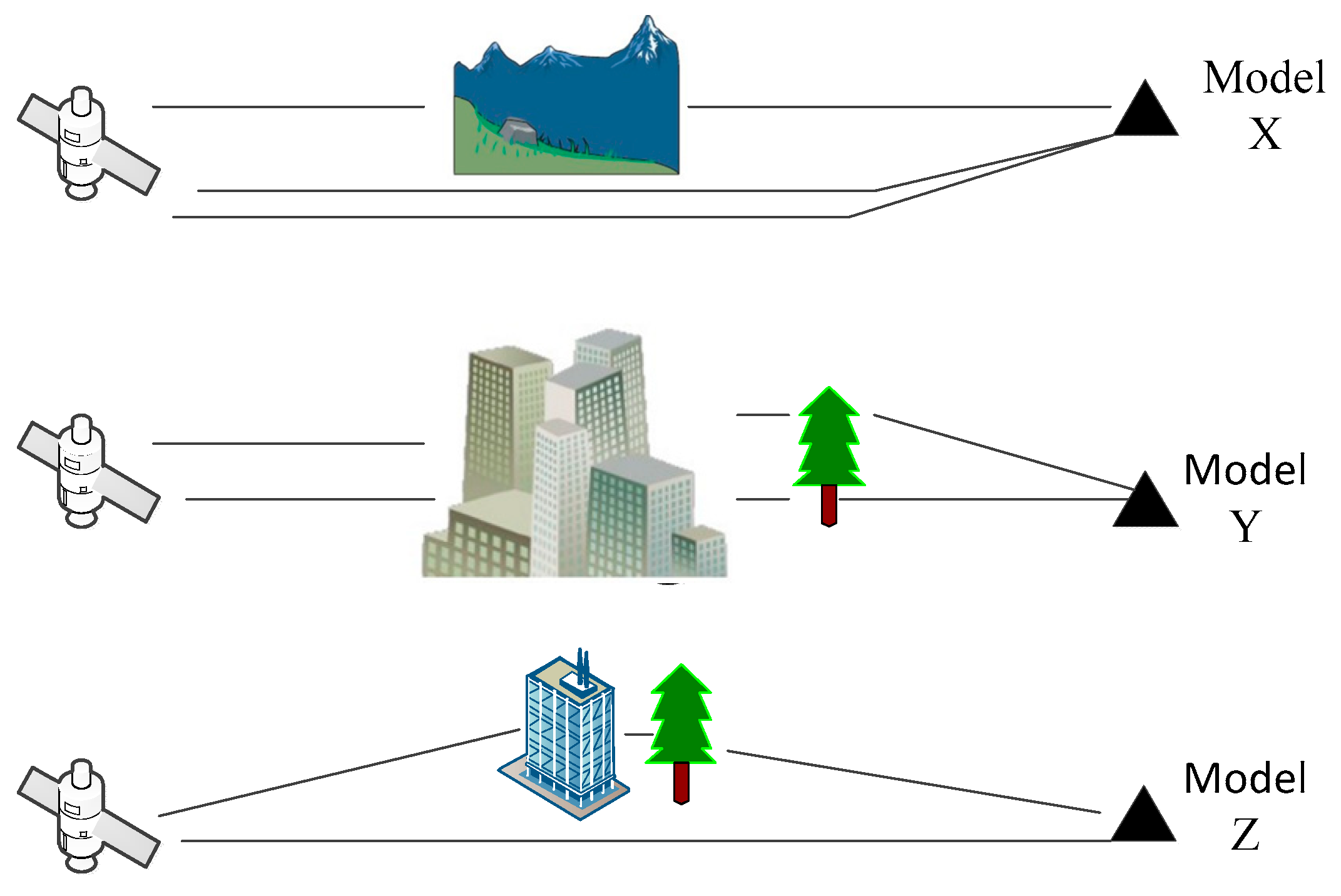
According to Reference [33], the main models of satellite communication channel are the C. Loo model, Corazza model, and Lutz model. The C. Loo model is mainly suitable for rural environments. The received signals are mainly composed of direct shadowing signal components and multi-path signal components which are not shadowed. The Corazza model is applicable to all environments (roads, villages, cities, etc.). The signals received by users are affected by shadows. The Lutz model divides the channel environment between satellite and user into good and bad states. In the good state, there is no shadowing effect. In the bad state, there is no direct signal component. The above three models are represented as model X, model Y, and model Z, respectively. Three main propagation models of satellite communication links are shown in Figure 4.
We assume that the probability of satellite link transmission models X, Y, and Z are p X , p Y and p Z , respectively. From this, we get a three-element model space S = { S X , S Y , S Z } . The state transition probability matrix Λ between the three models is
Λ = ( P X X   P X Y   P X Z P Y X   P Y Y   P Y Z P Z X   P Z Y   P Z Z ) = ( 1 Δ t < Γ X > Δ t 2 p X ( p X < Γ X > + p Y < Γ Y > p Z < Γ Z > )   Δ t 2 p X ( p X < Γ X > + p Z < Γ Z > p Y < Γ Y > ) Δ t 2 p Y ( p X < Γ X > + p Y < Γ Y > p Z < Γ Z > ) 1 Δ t < Γ X >     Δ t 2 p Y ( p Y < Γ Y > + p Z < Γ Z > p X < Γ X > ) Δ t 2 p Z ( p X < Γ X > + p Z < Γ Z > p Y < Γ Y > )   Δ t 2 p Z ( p Y < Γ Y > + p Z < Γ Z > p X < Γ X > ) 1 Δ t < Γ X > ) ,
where Δ t is the smallest unit of time for state transition between two transmission models, and < Γ X > ,   < Γ Y > and < Γ Z > represent the average time of model states X, Y and Z, respectively.
We assume that the transmission link between satellite and user is time-varying and can be modeled as a finite-state Markov chain model. In this model, the quality of the channel is expressed as the signal-to-noise ratio (SNR) of the signal received by the user. We assume that the SNR of the signal received by user u from LEO satellite l is the random variable h u l . The value range of h u l can be divided into L segments: h 0 * h u l h 1 * , H 0 ; h 1 * h u l h 2 * , H 1 ; …; h u l h L 1 * , H L 1 . Each segment conforms to a Markov chain model and has L segments, that is, H = { H 0 , H 1 , , H L 1 } . At time t, the SNR of the signal received by user u from LEO satellite l is h u l ( t ) , where t { 0 , 1 , 2 , , T 1 } . According to a certain transition probability, the SNR h u l ( t ) is transferred from one state to another state. Let γ S 31 ¯ S 32 ¯ ( t ) denote the probability of transition from state S 31 ¯ to state S 32 ¯ . The state transition probability matrix of transmission channel between user u and LEO satellite l can be expressed as an L × L dimensional matrix ƛ u l ( t ) .
ƛ u l ( t ) = [ γ S 31 ¯ S 32 ¯ ( t ) ] L × L ,
where ƛ S 31 ¯ S 32 ¯ ( t ) = P r ( h u l ( t + 1 ) = S 32 ¯ | h u l ( t ) = S 31 ¯ ) , S 31 ¯ , S 32 ¯ H .
We assume that the available spectrum bandwidth of the LEO satellite l is B l Hz, where B u l Hz is allocated to user u. The available return capacity of satellite l is Z l bps. User u’s spectrum utilization at time t is v u l ( t ) . Then, the communication rate between user u and LEO satellite l is
C o m R u l ( t ) = a u l ( t ) B u l ( t ) v u l ( t ) , u u a ,
and u u a C o m R u l ( t ) Z l , l l a , where a u l ( t ) indicates whether user u is connected to LEO satellite l. a u l ( t ) = 1 indicates that user u is connected to LEO satellite l; otherwise, a u l ( t ) = 0 .

3.5. Caching Model

Based on the analysis of Section 3.3.2, users in the SIN have I tasks. Each task is arranged in descending order of importance. Task i represents the important task of the i-th item. The request rate of task i at time t is shown in Equation 15. The arrival process of task i obeys Poisson distribution with a ϖ parameter. The content of the task request satisfies a Zipf-like distribution. The probability of task i is 1 / ρ i α , where ρ = i = 1 I 1 / i α , α is a Zipf slope, and 0 < α 1 [34].
We cannot determine whether task i is cached first. Therefore, we assume that task i is cached as a random variable ς i . If task i is not cached, then ς i = 0 ; otherwise, ς i = 1 , constituting a Markov chain model ς i = { 0 , 1 } with two states. The cache state of time t can be expressed as ς   i ( t ) , t { 0 , 1 , 2 , , T 1 } . According to a certain transition probability, the cache state ς   i ( t ) is transferred from one state to another state. Let J S 41 ¯ S 42 ¯ ( t ) denote the probability of transition from state S 41 ¯ to state S 42 ¯ ; then, the transition probability matrix Φ i ( t ) is obtained as follows:
Φ i ( t ) = [ J S 41 ¯ S 42 ¯ ( t ) ] 2 × 2 ,
where J S 41 ¯ S 42 ¯ ( t ) = Pr ( ς i ( t + 1 ) = S 42 ¯ | ς i ( t ) = S 41 ¯ ) , S 41 ¯ , S 42 ¯ ς i [35].

3.6. Computing Model

Let user u have computing task T u = { o u , n u } , where o u represents the size of the task content, and n u represents the number of cycles that the central processing unit (CPU) needs to run to complete the task. Because there are multiple users and MEC servers, it is impossible to know how much computing power is allocated to user u. Therefore, a random variable Ξ u m is established to represent the computing power of assigning MEC server m to user u. Ξ u m is divided into M discrete intervals, Π = { Π 0 , Π 1 , , Π M 1 } . The computing state of time t can be expressed as Ξ u m ( t ) , t { 0 , 1 , 2 , , T 1 } . According to a certain transition probability, the computing state Ξ u m ( t ) is transferred from one state to another state. Let ε S 51 ¯ S 52 ¯ ( t ) denote the probability of transition from state S 51 ¯ to state S 52 ¯ . The state transition probability matrix E u m ( t ) of M × M dimension can be expressed as
E u m ( t ) = [ ε S 51 ¯ S 52 ¯ ( t ) ] M × M ,
where ε S 51 ¯ S 52 ¯ ( t ) = ( P r Ξ u m ( t + 1 ) = S 52 ¯ | Ξ u m ( t + 1 ) = S 51 ¯ ) , S 51 ¯ , S 52 ¯ Π .
The execution time of task T u on MEC server m is
t u m = n u Ξ u m ( t ) .
Thus, the computing rate is
C o m p R u m ( t ) = a u m ( t ) o u t u m = a u m ( t ) Ξ u m ( t ) o u n u ,
and u u a a u m ( t ) o u O m , where a u m ( t ) indicates whether the user uses the MEC server m. a u m ( t ) = 1 means that the user uses MEC server m; otherwise, a u m ( t ) = 0 . O m represents the maximum value that can be calculated on server m [36].

4. Problem Equation

Based on the satellite coverage and transmission model, communication link model, caching model, and computing model established in Section 3, this section models the allocation of multi-dimensional resources in the SIN as a deep reinforcement learning process. Next, the state set, action set, reward function, and A3C algorithm flow in the process of deep reinforcement learning are analyzed.

4.1. State Set

The state set of the SIN includes the elevation state between user and satellite, transmission state of GEO data relay satellite, communication link state, caching state, and computing state. Therefore, the state set S (t) of time t can be expressed as
S ( t ) = [ w u 1 ( t )   w u 2 ( t )     w u L ( t ) l 1 ( t )   l 2 ( t )     l L g ( t ) h u 1 ( t )   h u 2 ( t )     h u L ( t ) Γ u 1 ( t )   Γ u 2 ( t )     Γ u C ( t ) Ξ u 1 ( t )   Ξ u 2 ( t )     Ξ u M ( t ) ] ,
where Γ u c ( t ) = [ ς   1 ( t ) , ς   2 ( t ) , , ς   i ( t ) , ς   I ( t ) ] , ς   i ( t ) [ 0 , 1 ] , l L g ( t ) = [ 1 ( t ) , 2 ( t ) , , i ( t ) , I ( t ) ] , and i ( t ) [ 0 , 1 ] .

4.2. Action Set

In the dynamic change of the SIN, we use a deep reinforcement learning algorithm to decide which LEO satellite is connected to user u, whether the tasks of user u need GEO data relay satellite for transmission, whether the tasks of user u are cached, and which MEC server is used to compute the tasks of user u. Therefore, the set of actions at time t is
a u ( t ) = { C o m A u ( t ) , C o m A l ( t ) , C a A u ( t ) , C o m p A u ( t ) } ,
where the following apply:
(1) C o m A u ( t ) = [ C o m A u 1 ( t ) , C o m A u 2 ( t ) , , C o m A u l ( t ) , C o m A u L ( t ) ] , C o m A u l ( t ) { 0 , 1 } . When C o m A u l ( t ) = 0 , it means that user u is not connected to LEO satellite l at time t; otherwise, C o m A u l ( t ) = 1 . In this paper, at any time, it is assumed that only one LEO satellite is connected to the user u; thus, l l a C o m A u l ( t ) = 1 , u u a .
(2) C o m A l ( t ) = [ C o m A l 1 ( t ) , C o m A l 2 ( t ) , , C o m A l l g ( t ) , C o m A l L g ( t ) ] , C o m A l l g ( t ) { 0 , 1 } . When C o m A l l g ( t ) = 0 , it means that the task is not transmitted by GEO data relay satellite lg; otherwise, C o m A l l g ( t ) = 1 . In this paper, at any time, it is assumed that only one GEO data relay satellite is connected to the LEO satellite; thus, l g Î l g a C o m A l l g ( t ) = 1 , l l a .
(3) C a A u ( t ) = [ C a A u 1 ( t ) , C a A u 2 ( t ) , , C a A u c ( t ) , C a A u C ( t ) ] , C a A u c ( t ) { 0 , 1 } . When C a A u c ( t ) = 0 , it means that the task is not cached by cache c; otherwise, C a A u c ( t ) = 1 . In this paper, at any time, suppose there is only one cache to cache a specified task; thus, c c a C a A u c ( t ) = 1 , u u a .
(4) C o m p A u ( t ) = [ C o m p A u 1 ( t ) , C o m p A u 2 ( t ) , , C o m p A u m ( t ) , C o m p A u M ( t ) ] , C o m p A u m ( t ) { 0 , 1 } . When C o m p A u m ( t ) = 0 , it means that the task was not handed over to MEC server m for computing; otherwise, C o m p A u m ( t ) = 1 . In this paper, at any time, it is supposed that there is only one MEC server to compute a specified task; thus, m m a C o m p A u m ( t ) = 1 , u u a .

4.3. Reward Function

According to Reference [37], SDN managers of the SIN need to pay for LEO satellite l, GEO data relay satellite lg, cache c, and MEC server m. It is assumed to pay δ l to the LEO satellite every Hz, δ l g to the GEO data relay satellite per Hz, ς c to the cache per unit storage space, and η m to the MEC server per joule.
In addition, the SIN managers need to charge users for information transmission, caching, and computing. Suppose τ u is charged per bit of transmission information, κ u is charged per bit of cache information, and ϕ u is charged per bit of calculation information. The reward function is
R u ( t ) = l l a R u , l c o m m ( t ) + l g l g a R l , l g c o m m ( t ) + c c a R u , c c o c h e ( t ) + m m a R u , m c o m p ( t ) = l l a w u l ( t ) C o m A u l ( t ) ( τ u C o m R u l ( t ) / δ l B u l ( t ) ) + lg lg a w u l ( t ) C o m A l lg ( t ) ( τ u C o m R l l g ( t ) / δ l g B l l g ( t ) ) + c c a w u l ( t ) C a A u c ( t ) ( κ u C a R u c ( t ) / ς c o u ) + m m a w u l ( t ) C o m p A u m ( t ) ( ϕ u C o m p R u m ( t ) / η m n u e m ) = l l a w u l ( t ) C o m A u l ( t ) ( τ u B u l ( t ) v u l ( t ) / δ l B u l ( t ) ) + lg lg a w u l ( t ) C o m A l lg ( t ) ( τ u B l l g ( t ) v l l g ( t ) / δ l g B l l g ( t ) ) + c c a w u l ( t ) C a A u c ( t ) ( κ u B u l ( t ) v u l ( t ) ς u c ( t ) / ς c o u ) + m m a w u l ( t ) C o m p A u m ( t ) ( ϕ u Ξ u m ( t ) o u n u / η m n u e m )
where e m represents the energy consumed by the CPU to rotate a circle. We define the reward function R u ( t ) as the expected benefit of the unit resource at time t, that is, the ratio of the fee charged to the user and the fee paid to obtain the resource. The higher the value of R u ( t ) is, the higher the utilization rate of resources will be.

4.4. A3C Algorithm

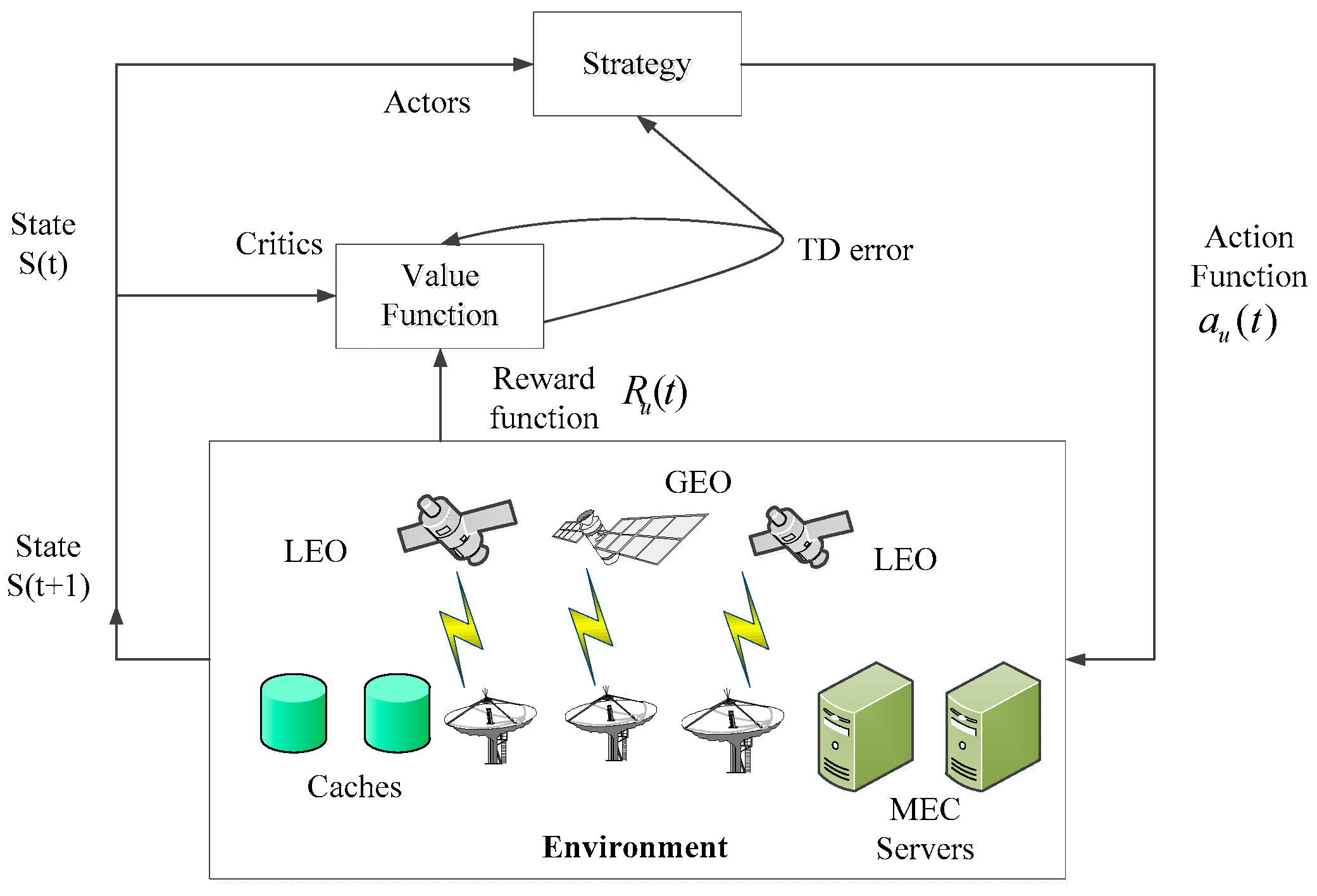
In this paper, we need to consider the coverage of the LEO satellite, transmission status of the GEO data relay satellite, communication link status, cache status, and computing power of the MEC server. Moreover, the SIN is a dynamic network system which is constantly changing. Therefore, this paper adopts the A3C algorithm in the deep reinforcement learning algorithm. The A3C algorithm is a deep reinforcement learning algorithm which combines a use value function and a strategy gradient. The actor part can dynamically change the strategy according to the learned value function. The critic part estimates the current state (action) value function and evaluates the actor’s strategy [38]. The basic framework of the A3C algorithm based on the SIN is shown in Figure 5.
In the A3C algorithm, first of all, we define the learning strategy as ι . The value function V ι ( s ) and action value function Q ι ( s , a ) are used to judge the learning strategy. The value function V ι ( s ) of the current initial state s is defined as
V ι ( s ) = E ι [ k = 0 ϒ k R u ( t + k + 1 ) i | S t = s ] ,
where E ι [ * ] represents mathematical expectations under certain state transition probabilities and learning strategies, R u ( t ) represents the reward function, and ϒ is the discount factor, ϒ [ 0 , 1 ] . ϒ is used to measure the role of reward function in value function. The farther it is away from the current state, the smaller the value of ϒ will be.
Each strategy represents a mapping from state to action space, i.e., a = ι ( s ) . The action value function Q ι ( s , a ) is defined as
Q ι ( s , a ) = E ι [ k = 0 ϒ k R u ( t + k + 1 ) | S t = s , a u ( t ) = a ] .
Actor networks can be divided into three parts. Assuming that the network parameter of the Actor part is Θ , the following results are obtained:
(1) Revenue function: J ( Θ ) = V ι Θ ( s ) = E ι Θ [ V ] ;
(2) Derivation of strategy function: Θ ι Θ ( s , a ) = ι Θ ( s , a ) Θ log ι Θ ( s , a ) ;
(3) Renewal of income gradient through gradient: Θ J ( Θ ) = E ι Θ ( s , a ) [ Θ log ι Θ ( s , a ) V ι Θ ( s ) ] .
For the Critic part, set the network parameter as Θ c . When the Actor network and the Critic network are finally determined, V Θ c ( s ) V ι Θ ( s ) . The optimal strategy obtained through Actor and Critic networks is the same. Therefore, the gradients of the two should be equal, i.e., Θ c V Θ c ( s ) = Θ log ι Θ ( s , a ) .
After the above deduction, we define the loss function as ε = E ι [ ( V ι Θ ( s ) V Θ c ( s ) ) 2 ] . When the loss function is minimized, its minimum value is obtained when the derivative is 0. It can be concluded that Θ c ε = 0 . Further derivation shows that
E ι [ ( V ι Θ ( s ) V Θ c ( s ) ) Θ c V Θ c ( s ) ] = 0 E ι [ ( V ι Θ ( s ) V Θ c ( s ) ) Θ log ι Θ ( s , a ) ] = 0 E ι [ V ι Θ ( s ) Θ log ι Θ ( s , a ) ] = E ι [ V Θ c ( s ) Θ log ι Θ ( s , a ) ]
Therefore, the gradient of the income function J ( Θ ) is
Θ J ( Θ ) = E ι Θ [ Θ log ι Θ ( s , a ) V Θ c ( s ) ] .
It is known that the network parameter of Actor part is Θ and that of the Critic part is Θ c . Since there are multiple threads in the A3C algorithm, we have two parameters in the thread: Θ and Θ c . Set the global counter T = 0 ; thus, each thread has its own counter t. The flow chart of the A3C algorithm is shown below.
Algorithm: Asynchronous Advantage Actor-Critic
Initialize thread step counter t 1
repeat
  Reset gradients: d Θ 0 and d Θ 0 d Θ c 0
  Synchronize thread-specific parameters Θ = Θ and Θ c = Θ c
   t s t a r t = t
  Get state S t
  repeat
    Perform a u ( t ) according to policy ι ( a u ( t ) | S t ; Θ )
    Receive reward R u ( t ) and new state S t + 1
     t t + 1
     T T + 1
  until terminal S t or t t s t a r t = t max
   R = { 0 for terminal   S t V ( S t , Θ c ) for non - terminal   S t / / Bootstrap   from   last   state
  for k { t 1 , , t s t a r t } do
     R R u ( k + 1 ) + ϒ R
    Accumulate gradients wrt Θ : d Θ d Θ + Θ log ι ( a k | S k ; Θ ) ( R V ( S k ; Θ c ) )
Accumulate gradients wrt Θ c : d Θ c d Θ c + ( R V ( S k ; Θ c ) 2 ) / Θ c
end for
Perform asynchronous update of Θ using d Θ and of Θ c using d Θ c
Until T > T max
(1) Thread counters are initialized to t = 1 . The network parameters Θ and Θ c are used to initialize the parameters Θ and Θ c in the thread.
(2) Iterate sequentially until the maximum number of executions t max is reached, or other termination states are encountered. In successive iterations, the action a u ( t ) is obtained by using the strategy function ι ( a u ( t ) | S t ; Θ ) . Execute this action to get the next state S ( t + 1 ) and the corresponding reward value R u ( t ) . The value function of each state is solved by the Critic network at this time.
R = { 0   In   case   of   termination V ( S t , Θ c )   General   situation
Update counters: t = t + 1 , T = T + 1 .
(3) In multiple sampling, it may be t max times, or it may end in advance. The Bellman equation is used to calculate the value function for each sampling result, and the network parameters of Actor and Critic are updated by gradient.
(4) After the number of iterations is reached, the parameters Θ and Θ c in each thread are used to update the network parameters Θ and Θ c of the whole Actor and Critic parts.

5. Simulation Analysis

5.1. Simulation Parameter Setting

In the experiment, the hardware environment was an Intel Core i7-8750 CPU, with 8 GB of memory and 1 TB of hard disk space. The software environment was Python3.6.1 with Tensorflow1.4.0, MATLAB R2014a [39].
We assumed that there were three GEO data relay satellites, five LEO communication satellites, seven MEC servers, and seven caches. The altitudes of the five LEO satellites were 500 km, 780 km, 1000 km, 1200 km, and 1400 km. The elevation angle between user u and LEO satellite l conforms to Markov chain model. Assuming that the elevation angle is excellent, w u l = 10 , better, w u l = 8 , medium elevation, w u l = 6 , lower elevation, w u l = 4 , and extremely bad, w u l = 2 . We assume that the elevation state transition probability matrix is
κ = [ 0.4   0.1   0.2   0.2   0.1 0.1   0.4   0.1   0.2   0.2 0.2   0.1   0.4   0.1   0.2 0.2   0.2   0.1   0.4   0.1 0.1   0.2   0.2   0.1   0.4 ] .
Similarly, when the communication efficiency between user u and satellite l is very excellent, the spectrum utilization ratio is v u l ( t ) = 10 , better, v u l ( t ) = 8 , medium condition, v u l ( t ) = 5 , lower condition, v u l ( t ) = 1 , and extremely bad, v u l ( t ) = 0.2 . Its state transition probability matrix is
ƛ = [ 0.5   0.1   0.05   0.15   0.3 0.3   0.5   0.1   0.05   0.15 0.15   0.3   0.5   0.1   0.05 0.05   0.15   0.3   0.5   0.1 0.1   0.05   0.15   0.3   0.5 ] .
Assuming that there is a space task, whether it needs a GEO relay satellite transmission conforms to a Markov chain model, and its state transition probability matrix is
= [ 0.3   0.7 0.7   0.3 ] .
The cache state of the space task conforms to the Markov chain model, and its state transition probability matrix is
Φ = [ 0.6   0.4 0.4   0.6 ] .
For MEC servers, when the computing state is excellent, the computing rate is Ξ u m ( t ) = 50 , better, Ξ u m ( t ) = 30 , medium condition, Ξ u m ( t ) = 10 , lower condition, Ξ u m ( t ) = 3 , and extremely bad, Ξ u m ( t ) = 0.5 . Its state transition probability matrix is
E = [ 0.5   0.15   0.05   0.25   0.05 0.05   0.5   0.15   0.05   0.25 0.25   0.05   0.5   0.15   0.05 0.05   0.25   0.05   0.5   0.15 0.15   0.05   0.25   0.05   0.5 ] .
The remaining parameters in the simulation are shown in Table 2.
In this experiment, we simulated the expected benefits of unit resources in the following six situations as follows:
(1) Unified consideration of LEO satellite elevation state, communication link state, GEO data relay satellite transmission state, caching state, and computing state, expressed as A3C-based all scheme.
(2) Unified consideration of GEO data relay satellite transmission state, caching state, and computing state, regardless of LEO satellite elevation state and communication link state, expressed as A3C-based without coverage communication scheme.
(3) Unified consideration of LEO satellite elevation state, communication link state, caching status, and computing state, regardless of GEO data relay satellite transmission state, expressed as A3C-based without GEO communication.
(4) Unified consideration of LEO satellite elevation state, communication link state, GEO data relay satellite transmission state, and computing state, regardless of caching state, expressed as A3C-based without caching scheme.
(5) Unified consideration of LEO satellite elevation state, communication link state, GEO data relay satellite transmission state, and caching state, regardless of computing state, expressed as A3C-based without computing scheme.
(6) Direct allocation of resources under static network conditions, expressed as A3C-based no scheme [40].

5.2. Simulation Result

The simulation results in this paper are discussed below.
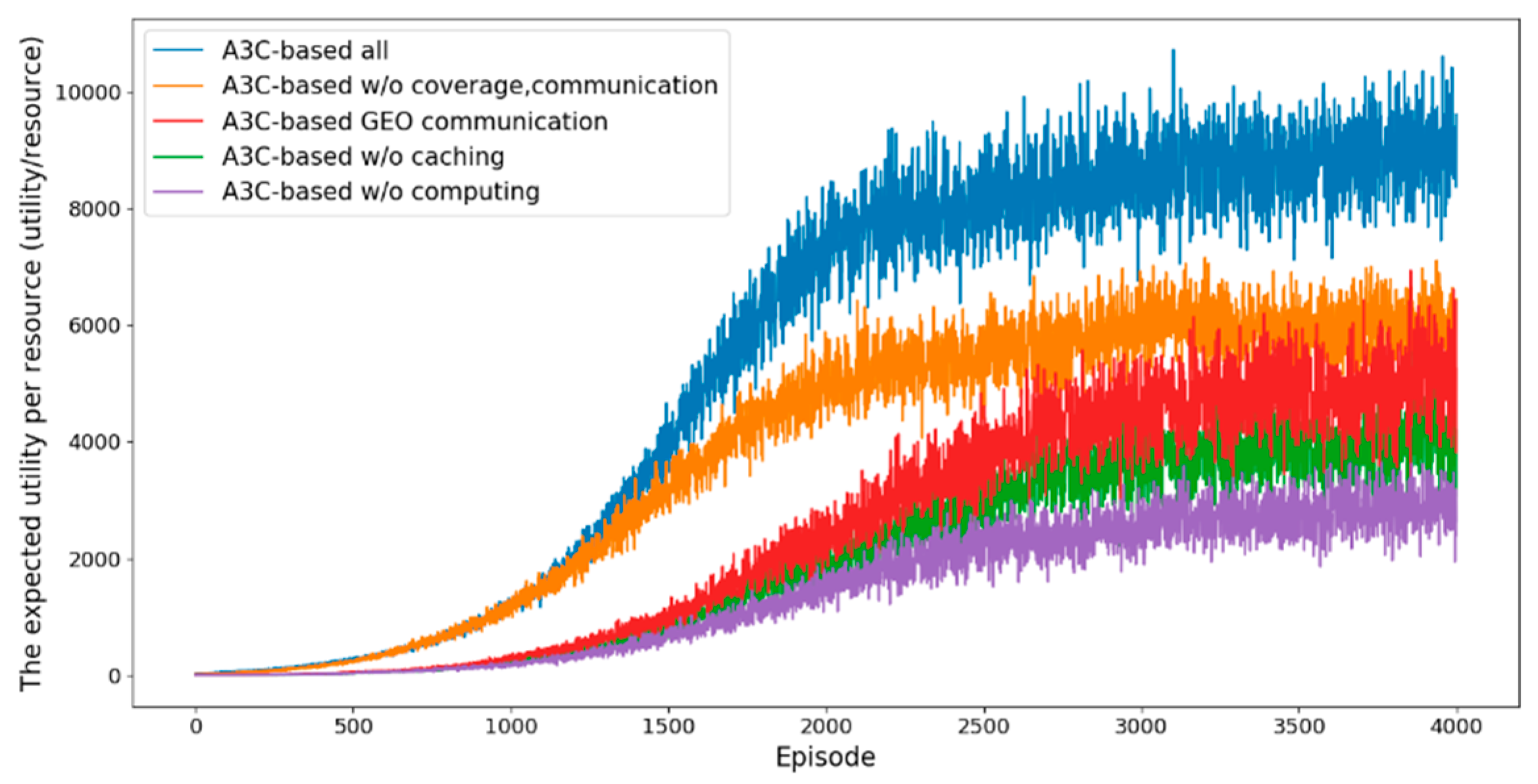
Figure 6 shows the convergence performance under different schemes. From the simulation, we can see that, at the beginning of deep reinforcement learning, the expected benefit per unit resource is low. With the increase of training times, the expected benefit of unit resources tends to be stable. The proposed A3C-based all scheme takes into account the coverage area of the LEO satellite, the communication link state between users and the LEO satellite, the transmission state of the GEO data relay satellite, the caching state of caches, and the computing state of the MEC server, which has better resource utilization efficiency.
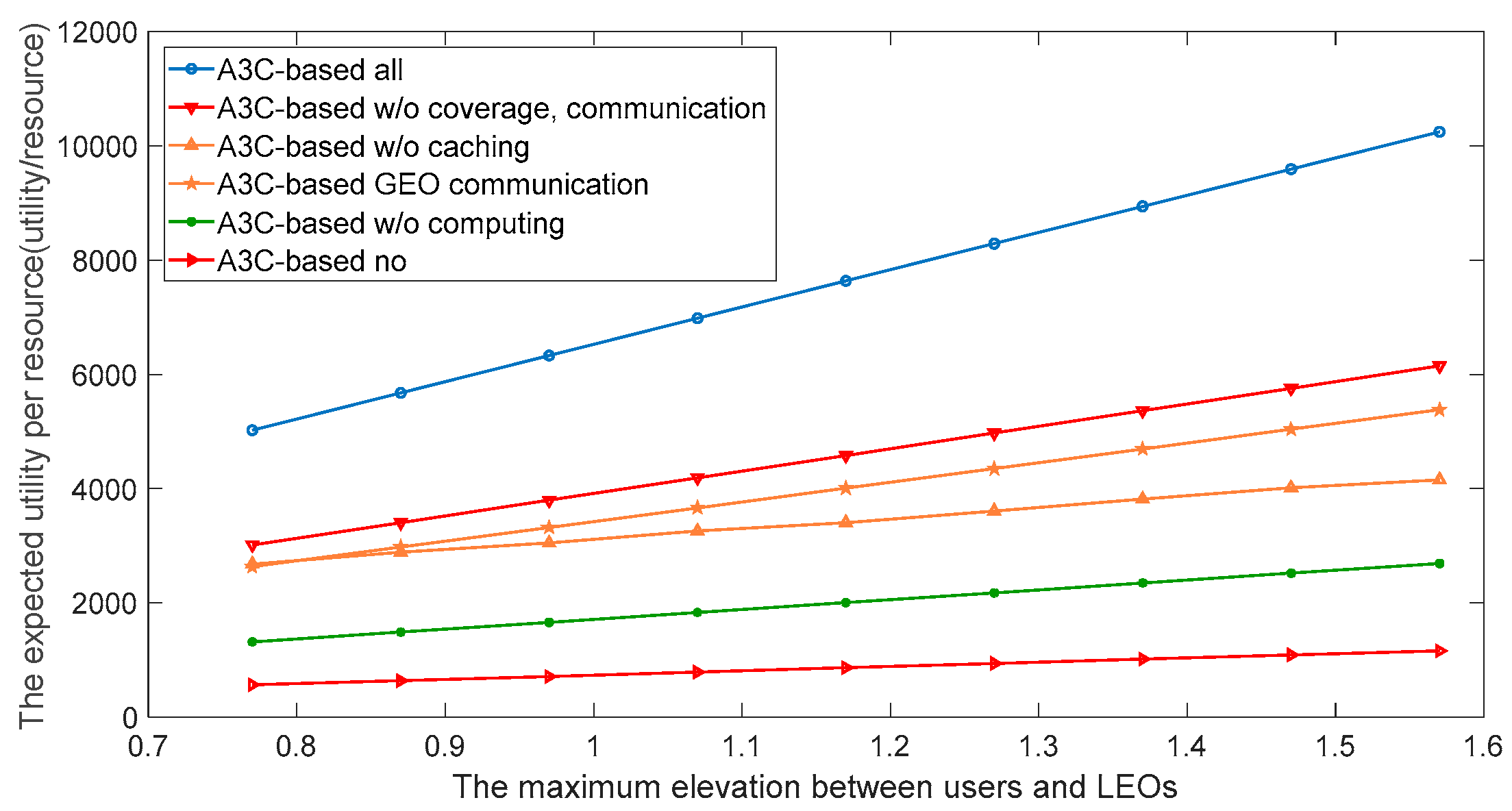
Figure 7 shows that with the increase in elevation angles of users and LEO satellites, the expected benefits per unit resource of the SIN increase gradually. The proposed A3C-based all scheme takes into account the coverage area of the LEO satellite, the communication link state between users and the LEO satellite, the transmission state of the GEO data relay satellite, the caching state of caches, and the computing state of the MEC server, which has better resource utilization efficiency.
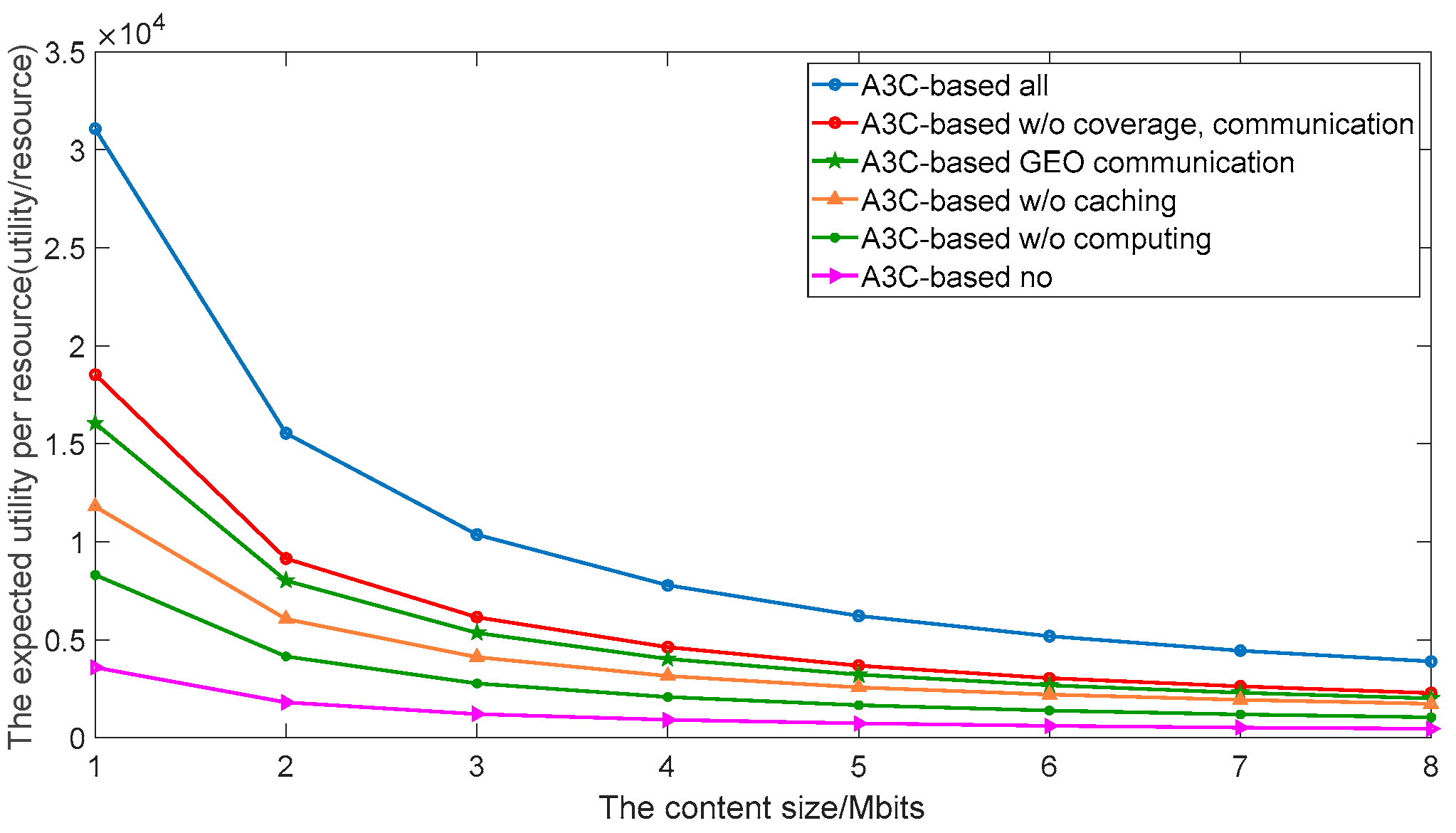
Figure 8 shows that, with the increase of the task content, the cost of caching charged to users increases gradually; thus, the expected benefit of unit resources of the SIN decreases gradually. The proposed A3C-based all scheme takes into account the coverage area of the LEO satellite, the communication link state between users and the LEO satellite, the transmission state of the GEO data relay satellite, the caching state of caches, and the computing state of the MEC server, which can achieve better expected benefits per unit resource.
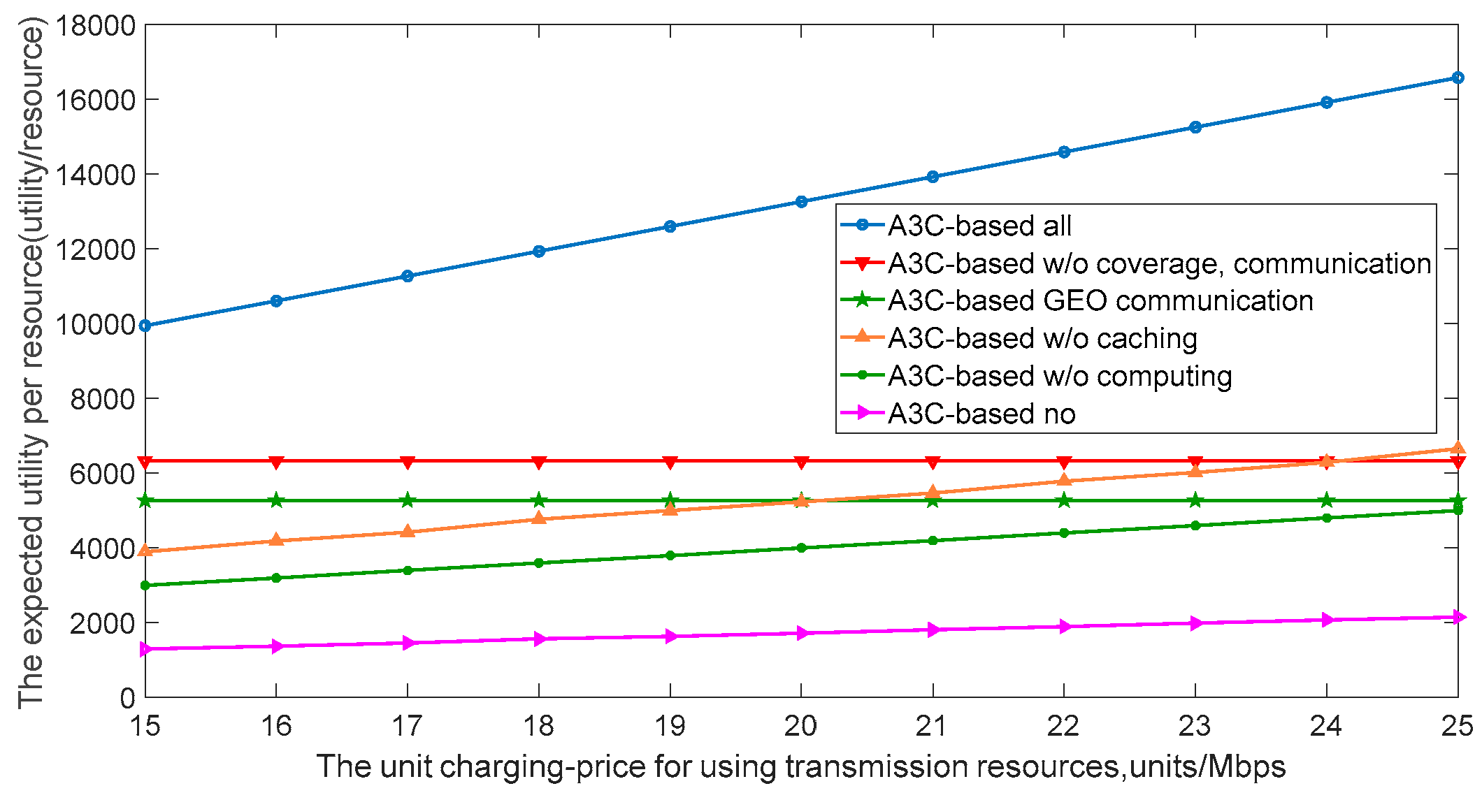
Figure 9 shows the relationship between the unit charging price for using transmission resources and the expected benefit of the unit resource. With the increase of the unit charging price for using transmission resources, the expected benefit of the unit resource of the SIN increases gradually. The scheme of A3C-based all takes into account the coverage area of the LEO satellite, the state of communication link between users and the LEO satellite, the transmission state of the GEO data relay satellite, the caching state of caches, and the computing state of the MEC server. It effectively improves the efficiency of unit resource utilization, and has more advantages than other schemes.
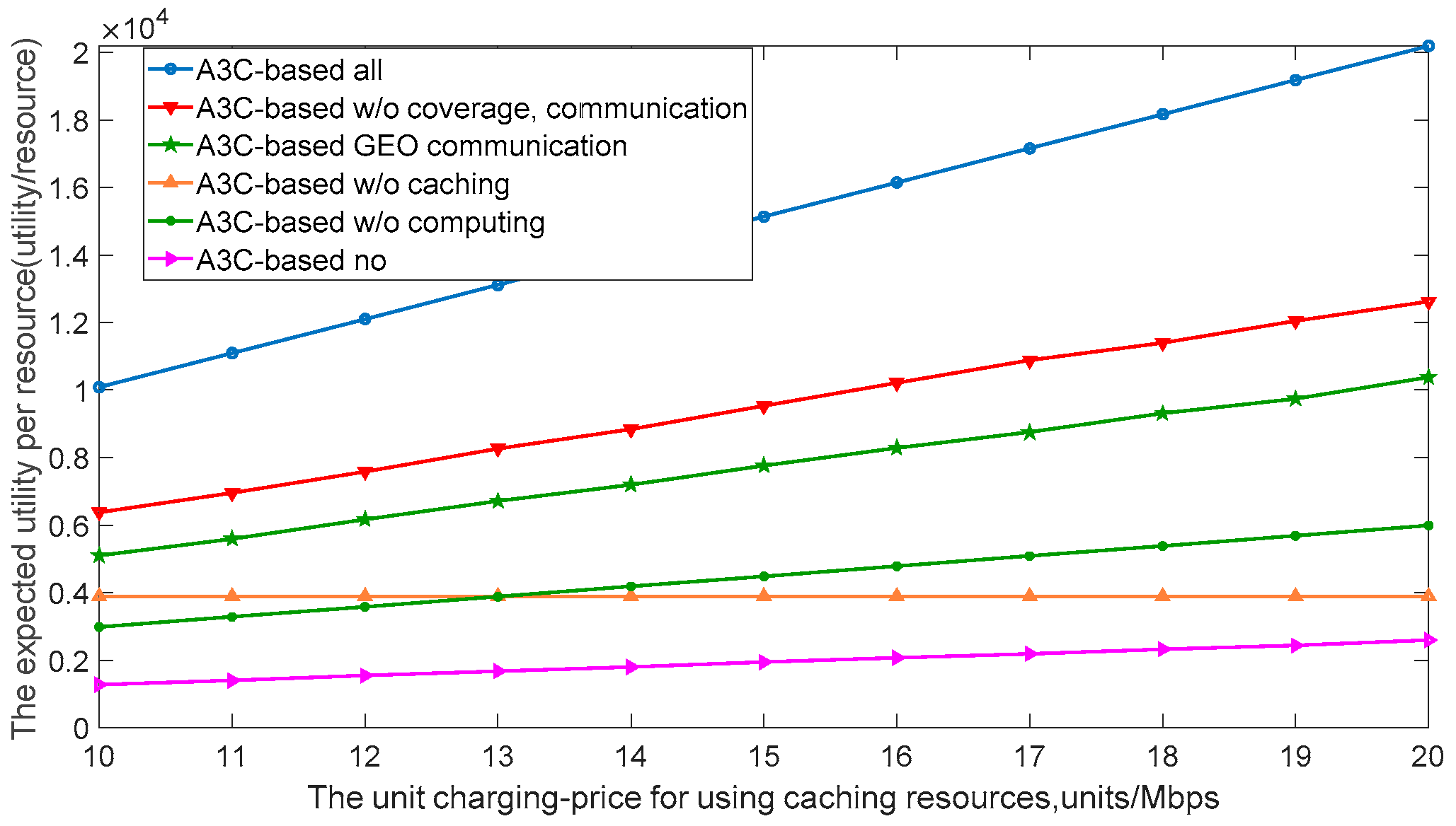
Figure 10 shows the relationship between the unit charging price for using caching resources and the expected benefit of the unit resource. With the increase of the unit charging price for using caching resources, the expected benefit of the unit resource of the SIN increases gradually. The scheme of A3C-based all takes into account the coverage area of the LEO satellite, the state of communication link between users and the LEO satellite, the transmission state of the GEO data relay satellite, the caching state of caches, and the computing state of the MEC server. It effectively improves the efficiency of unit resource utilization, and has more advantages than other schemes.
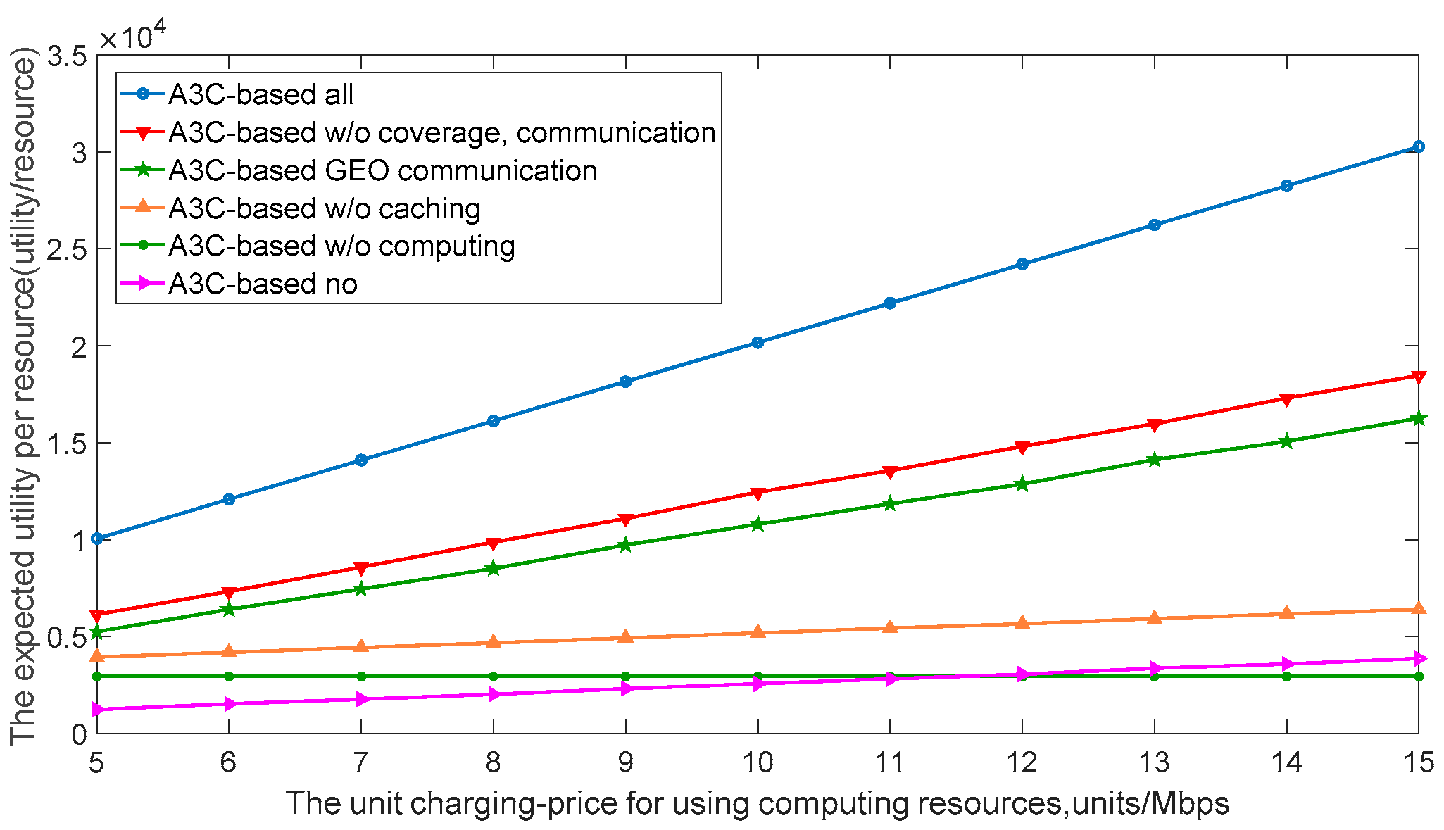
Figure 11 shows the relationship between the unit charging price for using computing resources and the expected benefit of the unit resource. With the increase of the unit charging price for using caching resources, the expected benefit of the unit resource of the SIN increases gradually. The proposed A3C-based all scheme takes into account the coverage area of the LEO satellite, the communication link state between users and the LEO satellite, the transmission state of the GEO data relay satellite, the caching state of caches, and the computing state of the MEC server, which has better resource utilization efficiency.

6. Conclusions

In this paper, in order to improve the resource management and utilization efficiency of the SIN, firstly, based on the core idea of SDN, a hierarchical and domain-controlled SIN architecture was established. The overall networking architecture and network control architecture were designed. On this basis, the transmission resources, caching resources, and computing resources of the SIN were managed in a unified way. Next, the satellite coverage and transmission model, communication link model, caching model, and computing model of the SIN were modeled and analyzed. Finally, the A3C algorithm of deep reinforcement learning was introduced to model and simulate the multi-dimensional resource allocation problem of the SIN. The simulation results show that the proposed scheme can effectively improve the expected benefits of unit resources and the utilization efficiency of the SIN resources. In this paper, LEO communication satellites and several GEO data relay satellites were taken as examples for analysis. However, the SIN is a huge system. In practical applications, the scheduling of remote-sensing satellites, navigation satellites, and other resources may have different situations, which need specific analysis. Furthermore, in a follow-up study, we will further analyze the other SIN resources such as energy resources and sensor resources.

Author Contributions

Conceptualization, X.M. and L.W.; Methodology, X.M. and L.W.; Software, X.M. and S.Y.; Validation, X.M.; Formal Analysis, X.M.; Investigation, X.M.; Resources, X.M. and S.Y.; Data Curation, X.M.; Writing-Original Draft Preparation, X.M.; Writing-Review & Editing, X.M.; Visualization, X.M.; Supervision, L.W.

Funding

China Equipment Named Research Funded Project with grant number 6142010010301.

Acknowledgments

The authors would like to thank Chao Qiu of Beijing University of Posts and Telecommunications for her guidance on the ideas for the text.

Conflicts of Interest

The authors declare no conflict of interest.

References

  1. Zhang, W. Topological Control Theory and Method of Space Information Network; PLA University Science and Technology: Nanjing, China, 2016; pp. 1–5. [Google Scholar]
  2. Wang, Y.; Sheng, M.; Zhuang, W.; Zhang, S.; Zhang, N.; Liu, R. Multi-Resource Coordinate Scheduling for Earth Observation in Space Information Networks. IEEE J. Sel. Areas Commun. 2018, 36, 268–279. [Google Scholar] [CrossRef]
  3. National Natural Science Foundation. The Program Guidance of the Basic Theory and Key Technology Research of Space Information Network in 2016. Available online: http://www.nsfc.gov.cn/publish/portal0/tab38/info51946.htm (accessed on 25 March 2016).
  4. Yu, Q.Y.; Meng, W.X.; Yang, M.C.; Zheng, L.M.; Zhang, Z.Z. Virtual multi-beamforming for distributed satellite clusters in space information networks. IEEE Wirel. Commun. 2016, 23, 95–101. [Google Scholar] [CrossRef]
  5. Li, D.R.; Shen, X.; Gong, J.Y.; Zhang, J.; Lu, J.H. On construction of China’s space information network. Wuhan Univ. Inf. Sci. Ed. 2015, 40, 711–715. [Google Scholar] [CrossRef]
  6. Cui, L.; Yu, F.R.; Yan, Q. When big data meets software-defined networking: SDN for big data and big data for SDN. IEEE Netw. 2016, 30, 58–65. [Google Scholar] [CrossRef]
  7. Li, T.X.; Zhou, H.C.; Xu, Q. SAT-FLOW: Multi-Strategy Flow Table Management for Software Defined Satellite Networks. IEEE Access 2017, 5, 14952–14965. [Google Scholar] [CrossRef]
  8. Gardikis, G.; Koumaras, H.; Sakkas, C.; Koumaras, V. Towards SDN/NFV-enabled satellite networks. Telecommun. Syst. 2017, 66, 1–14. [Google Scholar] [CrossRef]
  9. Liu, Q.; Zhai, J.W.; Zhang, Z.Z.; Zhong, S.; Zhou, Q.; Zhang, P. A Survey on Deep Reinforcement Learing. Chin. J. Comp. 2018, 1, 1–27. [Google Scholar] [CrossRef]
  10. Mnih, V.; Kavukcuoglu, K.; Silver, D.; Rusu, A.A.; Veness, J.; Bellemare, M.G.; Graves, A.; Riedmiller, M.; Fidjeland, A.K.; Ostrovski, G.; et al. Human-level control through deep reinforcement learning. Nature 2015, 518, 529–533. [Google Scholar] [CrossRef]
  11. Jennings, E.; Heckman, D. Performance Characterization of Space Communications and Navigation (SCaN) Network by Simulation. In Proceedings of the IEEE Aerospace Conference, Big Sky, MT, USA, 1–8 March 2008; pp. 1–9. [Google Scholar] [CrossRef]
  12. Vanderpoorten, J.; Cohen, J.; Moody, J.; Cornell, C.; Streland, A.; Breese, S. Transformational Satellite Communications System (TSAT) lessons learned: Perspectives from TSAT program leaders. In Proceedings of the 2012 IEEE Military Communications Conference, Orlando, FL, USA, 29 October–1 November 2012; pp. 1–6. [Google Scholar] [CrossRef]
  13. Sesena, J.; Alfaro, A.; Munoz, S. Regulatory environment for the successful ISICOM development. In Proceedings of the 2009 International Workshop on Satellite and Space Communications, Tuscany, Italy, 9–11 September 2009; pp. 109–112. [Google Scholar] [CrossRef]
  14. Axford, R.; Short, S.; Shchupak, P.; Muhammad, N. Wideband Global SATCOM (WGS) earth terminal interoperability demonstrations. In Proceedings of the 2012 IEEE Military Communications Conference, San Diego, CA, USA, 16–19 November 2008; pp. 1–6. [Google Scholar] [CrossRef]
  15. Schroth, K.; Burkhardt, N.; Che, T.S.; Pisano, D. IP networking over the AEHF MILSATCOM system. In Proceedings of the 2012 IEEE Military Communications Conference, Orlando, FL, USA, 29 October–1 November 2012; pp. 1–6. [Google Scholar] [CrossRef]
  16. Adinolfi, M.; Cesta, A. Heuristic scheduling of the DRS communication system. Eng. Appl. Artif. Intell. 1995, 8, 147–156. [Google Scholar] [CrossRef]
  17. Rojanasoonthon, S.; Bard, J.F.; Reddy, S.D. Algorithms for parallel machine scheduling: A case study of the tracking and data relay satellite system. J. Oper. Res. Soc. 2003, 54, 806–821. [Google Scholar] [CrossRef]
  18. Gu, Z.S. Research on the Relay Satellite Dynamic Scheduling Problem Modeling and Optimizational Technology; National University of Defense Technology: Changsha, China, 2008; pp. 11–26. [Google Scholar] [CrossRef]
  19. Bertaux, L.; Medjiah, S.; Berthou, P.; Abdellatif, S.; Hakiri, A.; Gelard, P.; Planchou, F.; Bruyere, M. Software defined networking and virtualization for broadband satellite networks. IEEE Commun. Mag. 2015, 53, 54–60. [Google Scholar] [CrossRef] [Green Version]
  20. Ferrús, R.; Koumaras, H.; Sallent, O.; Agapiou, G.; Rasheed, T.; Kourtis, M.-A.; Boustie, C.; Gélard, P.; Ahmed, T. SDN/NFV-enabled satellite communications networks: Opportunities, scenarios and challenges. Phys. Commun. 2016, 18, 95–112. [Google Scholar] [CrossRef] [Green Version]
  21. Gopal, R.; Ravishankar, C. Software Defined Satellite Networks. In Proceedings of the Aiaa International Communications Satellite Systems Conference, San Diego, CA, USA, 24–27 September 2013. [Google Scholar] [CrossRef]
  22. Yu, X.; Lei, W.M.; Song, L. A framework of SDN-based satellits on-board switching networks. J. PLA Univ. Sci. Tech. (Nat. Sci. Ed.) 2017, 18, 224–230. [Google Scholar] [CrossRef]
  23. Zhu, S.Y. Research on Routing Algorithm of Space Network Based on SDN; Harbin Institute of Technology: Harbin, China, 2017; pp. 1–19. [Google Scholar]
  24. Tian, R.; Yu, X.S.; Zhao, Y.L.; Wang, W.Z.; Li, Y.J.; Wang, C.F.; Zhang, J. Multi-path Carrying Strategy in SDN-based Space Information Networks. Radio Eng. 2016, 46, 63–67. [Google Scholar] [CrossRef]
  25. Tian, R. Research on Control Protocol and Routing Algorithms of Software Defined Space-Terrestrial Network; Beijing University of Posts and Telecommunications: Beijing, China, 2017; pp. 9–16. [Google Scholar]
  26. Zhang, S.M.; Zou, F.M. Survey on software defined network research. Appl. Res. Comput. 2013, 30, 2246–2251. [Google Scholar] [CrossRef]
  27. Nguyen, X.N.; Saucez, D.; Barakat, C. Rules Placement Problem in OpenFlow Networks: A Survey. IEEE Commun. Surv. Tutor. 2016, 18, 1273–1286. [Google Scholar] [CrossRef]
  28. Zhang, Q.; Li, M.; Deng, Y. Measure the structure similarity of nodes in complex networks based on relative entropy. Phys. A Stat. Mech. Appl. 2018, 491, 749–763. [Google Scholar] [CrossRef]
  29. Yang, B.; He, F.; Jin, J.; Xu, G.H. Analysis of Coverage Time and Handoff Number on LEO Satellite Comunication Systems. J. Electron. Inf. Technol. 2014, 36, 804–809. [Google Scholar] [CrossRef]
  30. Deng, B.; Jiang, C.; Kuang, L.; Guo, S.; Lu, J.; Zhao, S. Two-Phase Task Scheduling in Data Relay Satellite Systems. IEEE Trans. Veh. Technol. 2018, 67, 1782–1793. [Google Scholar] [CrossRef]
  31. Gomaa, H.; Messier, G.G.; Williamson, C.; Davies, R. Estimating Instantaneous Cache Hit Ratio Using Markov Chain Analysis. IEEE/ACM Trans. Netw. 2013, 21, 1472–1483. [Google Scholar] [CrossRef]
  32. Breslau, L.; Cao, P.; Fan, L.; Phillips, G.; Shenker, S. Web caching and Zipf-like distributions: Evidence and implications. Proc. IEEE INFOCOM 1999, 1, 126–134. [Google Scholar] [CrossRef]
  33. Li, H.Q. Hardware Implementation of LEO Satellite Channel Characteristic Emulation; Harbin Institute of Technology: Harbin, China, 2008; pp. 12–15. [Google Scholar]
  34. Theofanis, X.; Psannis, K.E. Caching Hit Probability and Compressive Sensing Perspective for Mobile Cellular Networks. Simul. Model. Pract. Theory 2018, 87, 92–98. [Google Scholar] [CrossRef]
  35. Daniel, G.; Gerson, S.; Jordi, C. Advanced prefetching and caching of models with PrefetchML. Softw. Syst. Model. 2018, 1–22. [Google Scholar] [CrossRef] [Green Version]
  36. Zhou, Y.; Yu, F.R.; Chen, J.; Kuo, Y. Resource Allocation for Information-Centric Virtualized Heterogeneous Networks with In-Network Caching and Mobile Edge Computing. IEEE Trans Veh. Technol. 2017, 66, 11339–11351. [Google Scholar] [CrossRef]
  37. He, Y.; Zhao, N.; Yin, H.X. Integrated Networking, Caching and Computing for Connected Vehicles: A Deep Reinforcement Learning Approach. IEEE Trans. Veh. Technol. 2018, 67, 44–55. [Google Scholar] [CrossRef]
  38. Helma, C.; Cramer, T.; Kramer, S.; Raedt, L.D. Data Mining and Machine Learning Techniques for the Identification of Mutagenicity Inducing Substructures and Structure Activity Relationships of Noncongeneric Compounds. J. Chem. Inf. Comput. Sci. 2018, 35, 1402–1411. [Google Scholar] [CrossRef]
  39. Jiang, S.W.; Guo, K.K.; Liao, J.; Zheng, G.A. Solving Fourier ptychographic imaging problems via neural network modeling and TensorFlow. Biomed. Opt. Express 2018, 9, 3306–3319. [Google Scholar] [CrossRef]
  40. Ying, H.; Cheng, C.L.; Richard, Y.; Zhu, H. Trust-based Social Networks with Computing, Caching and Communications: A Deep Reinforcement Learning Approach. IEEE Trans. Netw. Sci. Eng. 2018, 1–14. [Google Scholar] [CrossRef]
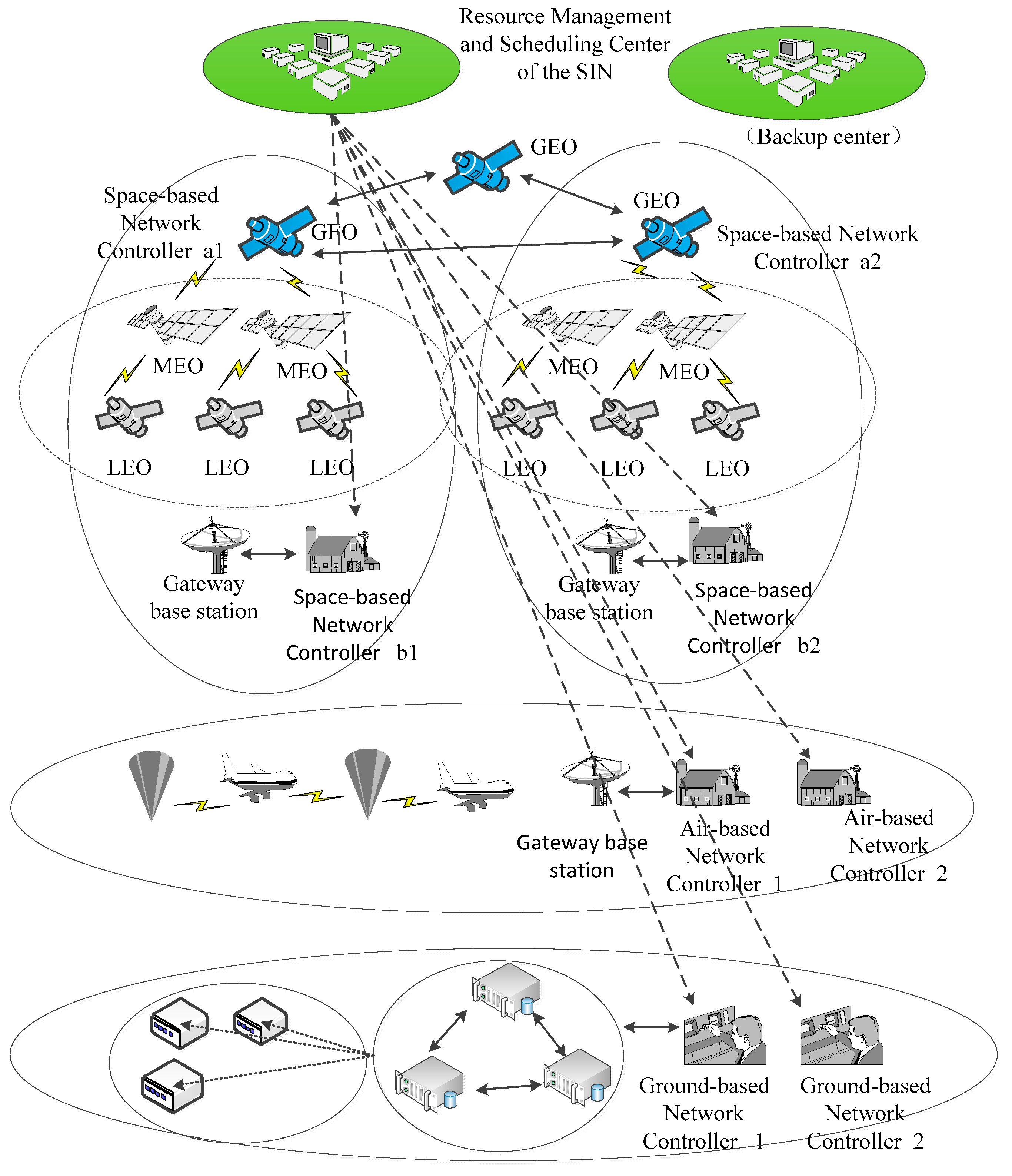
Figure 1. Overall networking architecture of the hierarchical and domain-controlled space information network (SIN) architecture.
Remotesensing 11 00448 g001
Figure 2. Network control architecture of the hierarchical and domain-controlled SIN architecture.
Remotesensing 11 00448 g002
Figure 3. Geometric diagram of low Earth orbit (LEO) satellite and user.
Remotesensing 11 00448 g003
Figure 4. Satellite channel model diagram.
Remotesensing 11 00448 g004
Figure 5. Framework of the Asynchronous Advantage Actor-Critic (A3C) algorithm based on the SIN.
Remotesensing 11 00448 g005
Figure 6. Convergence performance under different schemes.
Remotesensing 11 00448 g006
Figure 7. Expected benefits of unit resources under different elevation angles.
Remotesensing 11 00448 g007
Figure 8. Expected benefits of unit resources under different task content.
Remotesensing 11 00448 g008
Figure 9. The relationship between the unit charging price for using transmission resources and the expected benefit of unit resources.
Remotesensing 11 00448 g009
Figure 10. The relationship between the unit charging price for using caching resources and the expected benefit of unit resources.
Remotesensing 11 00448 g010
Figure 11. The relationship between the unit charging price for using computing resources and the expected benefit of unit resources.
Remotesensing 11 00448 g011
Table 1. Comparison of different space information network (SIN) architectures.
ArchitectureSatellite–Earth NetworkSpace-based NetworkSpace–net–Earth Network
Typical systemCivil: Inmarsat, O3b, OneWeb, Intersat
Military: WGS, MUOS
Civil: Iridium
Military: AEHF
Civil: SCaN, ISICOM
Military: TSAT
GroundGlobal distributed ground station networkThe system can operate independently of the ground stationThe earth and the sky cooperate with each other; the ground network does not need the global distribution of stations
Inter-satellite networkingNoYesYes
Equipment on satelliteSimpleComplexModerate
Difficulty of System MaintenanceSimpleComplexModerate
Technical complexitySimpleComplexModerate
Construction costLowHighModerate
Table 2. Simulation parameter setting. LEO—low Earth orbit; GEO—geostationary orbit; CPU—central processing unit.
ParametersValuesDescriptions
B u l 6 MHzBandwidth allocated by LEO satellite l to user u
B l l g 6 MHzBandwidth allocated by GEO satellite lg to user l
δ l 2 units/MHzPayment price using LEO spectrum resources
δ l g 2 units/MHzPayment price using GEO spectrum resources
ς c 4 units/MbitsPayment price using caching resources
η m 1 unit/JPayment price using computing resources
τ u 15 units/MbpsThe unit transmission fee charged to the user
κ u 10 units/MbpsThe unit caching fee charged to the user
ϕ u 5 units/MbpsThe unit computing fee charged to the user
θ u , max l π / 2 Maximum elevation between user u and satellite l
n u 6 McyclesNumber of cycles a CPU takes to complete each space task
e m 1 JThe energy consumed by the CPU in one lap
o u 3 MbitsTask content