An Object-Based Markov Random Field Model with Anisotropic Penalty for Semantic Segmentation of High Spatial Resolution Remote Sensing Imagery

Abstract

1. Introduction
2. The OMRF-AP Model for Image Segmentation
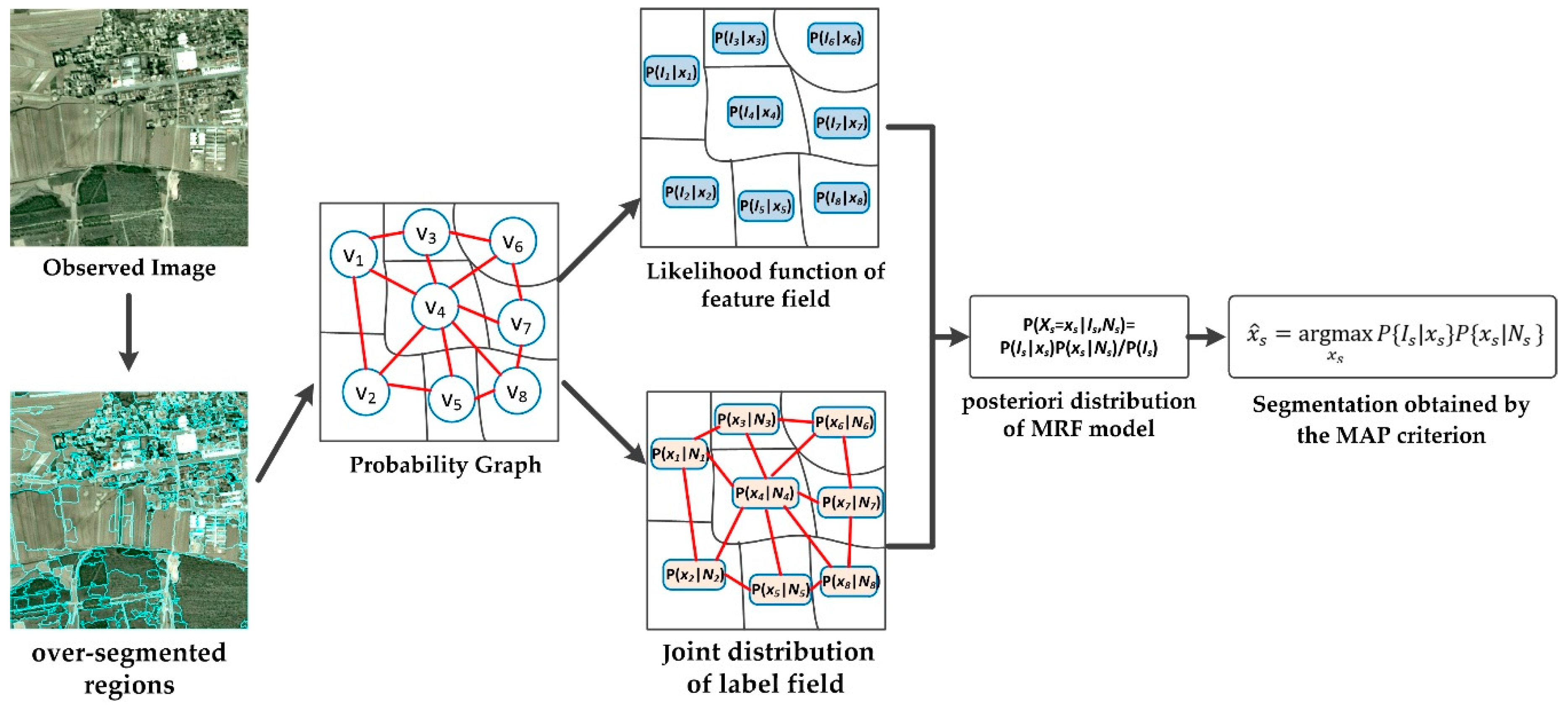
2.1. MRF Model for Image Segmentation
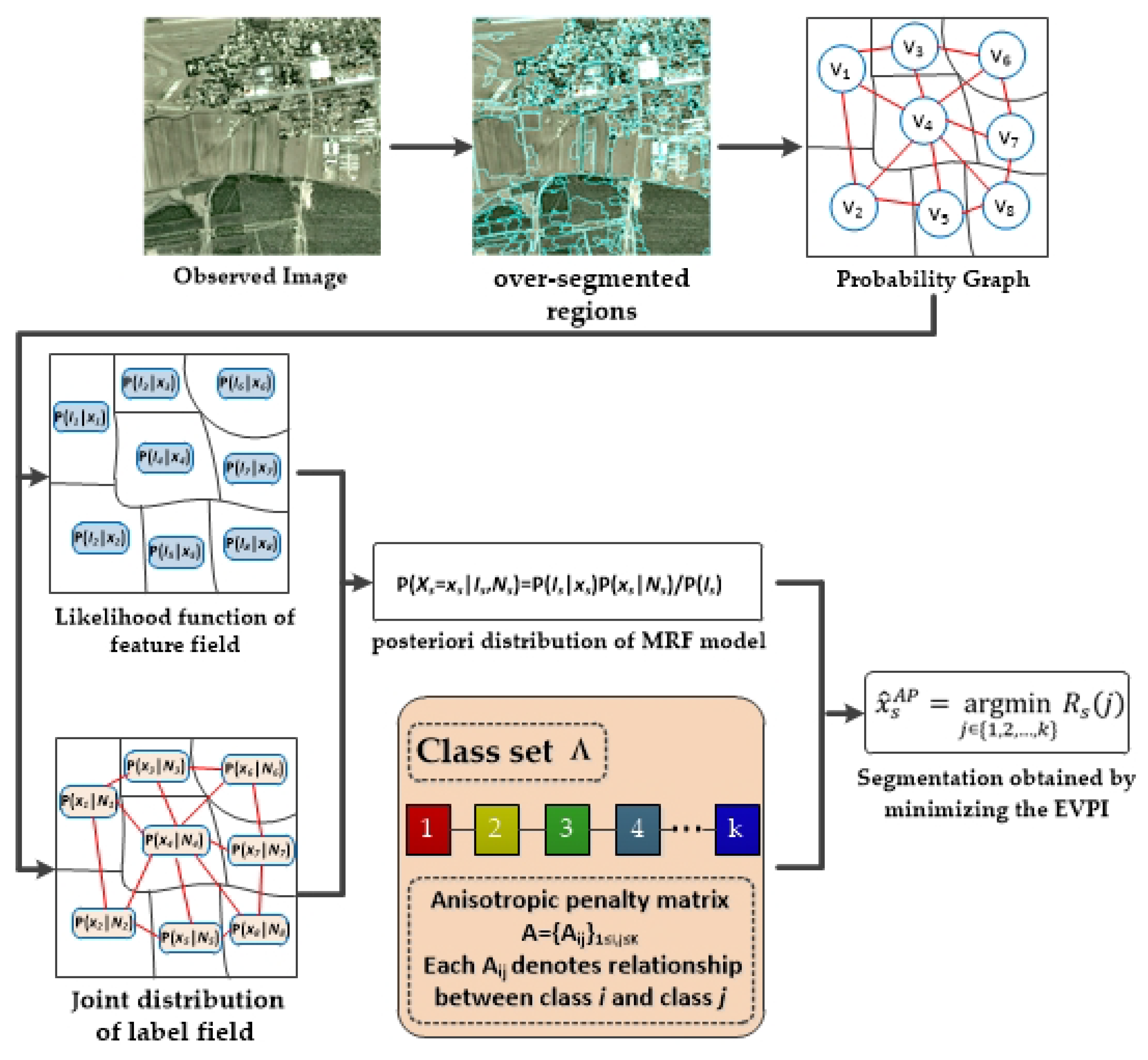
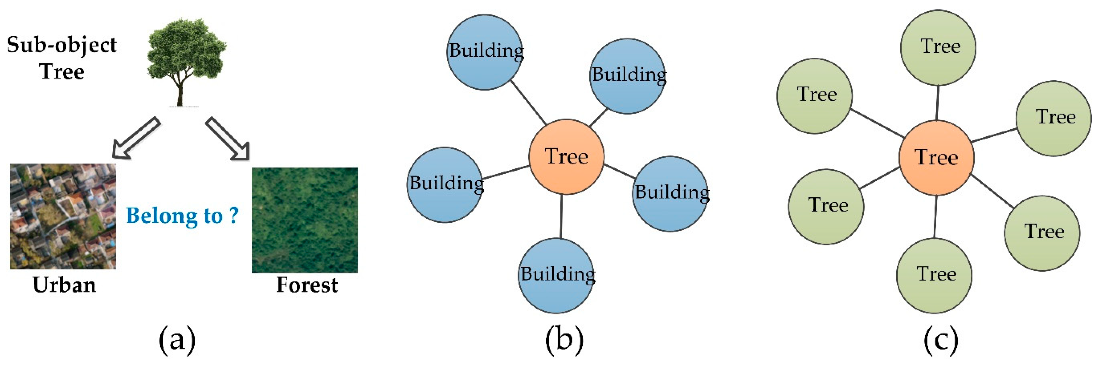
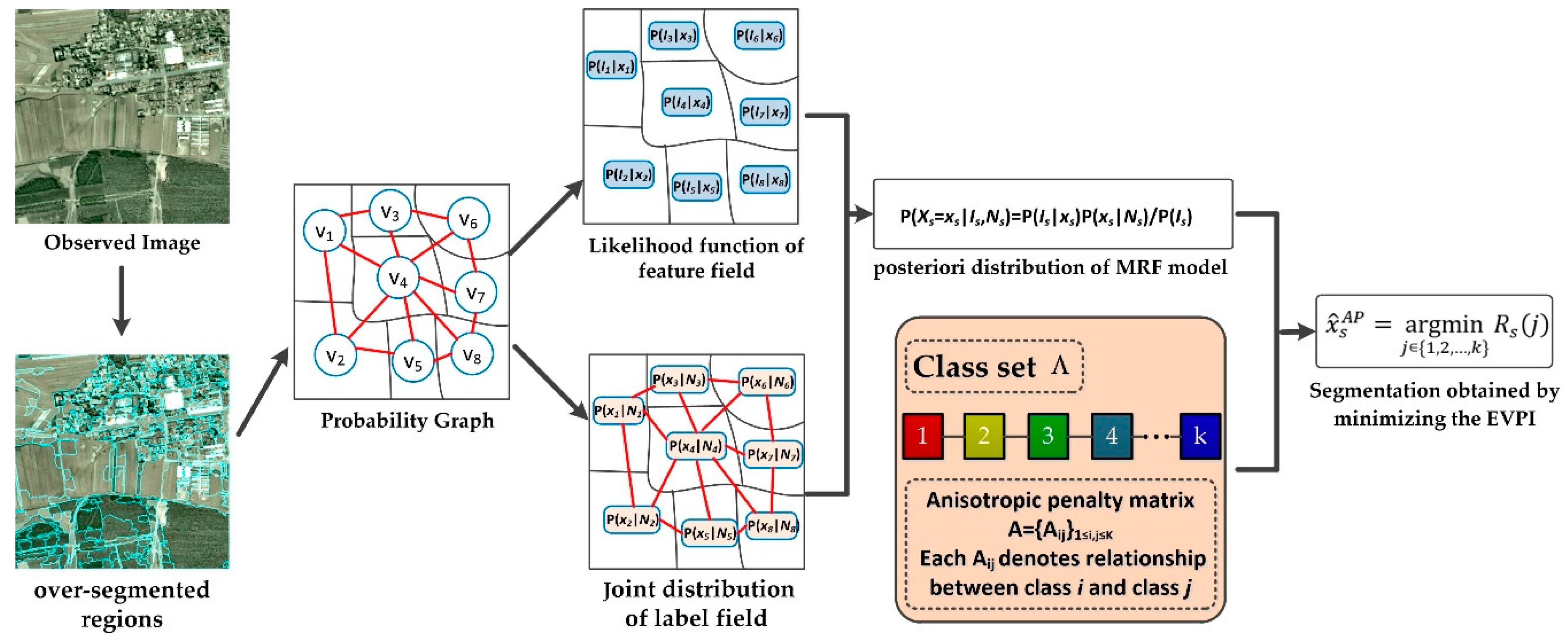
2.2. Proposed OMRF-AP Model
| Algorithm 1. OMRF-AP model |
| Input: the observed image , the number of classes , the anisotropic penalty matrix. Output: the segmentation result |
|
3. Experimental Results
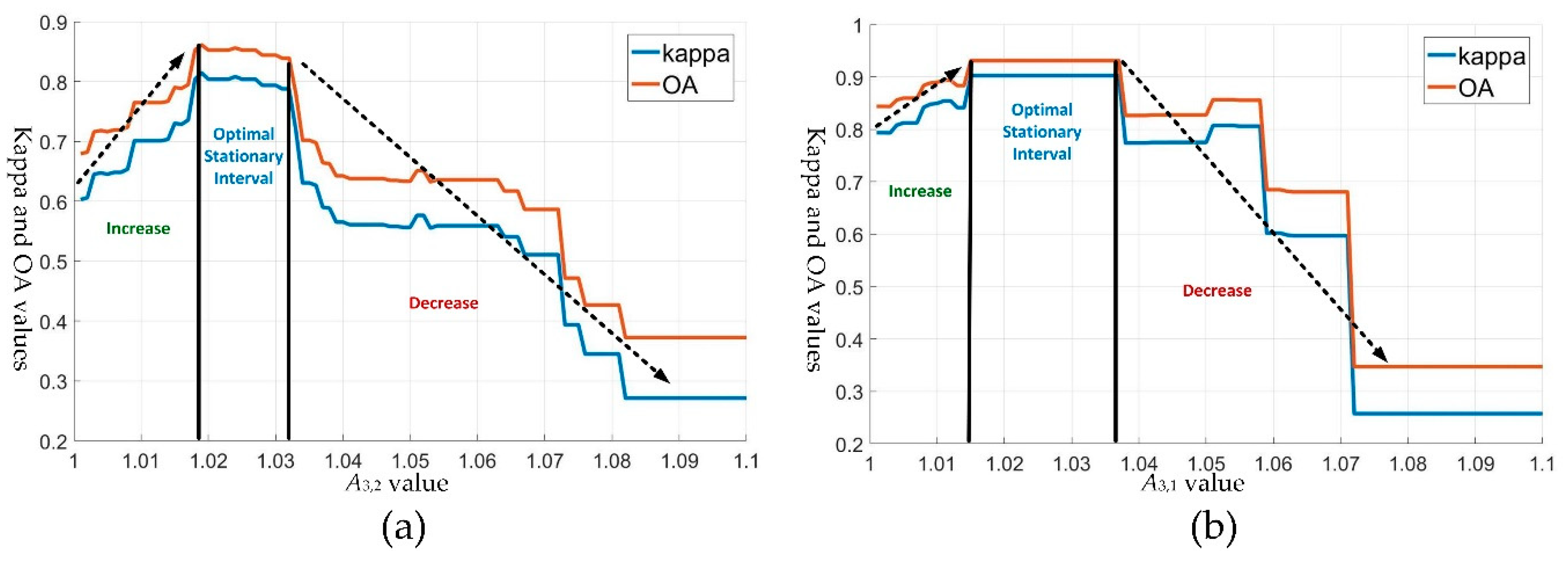
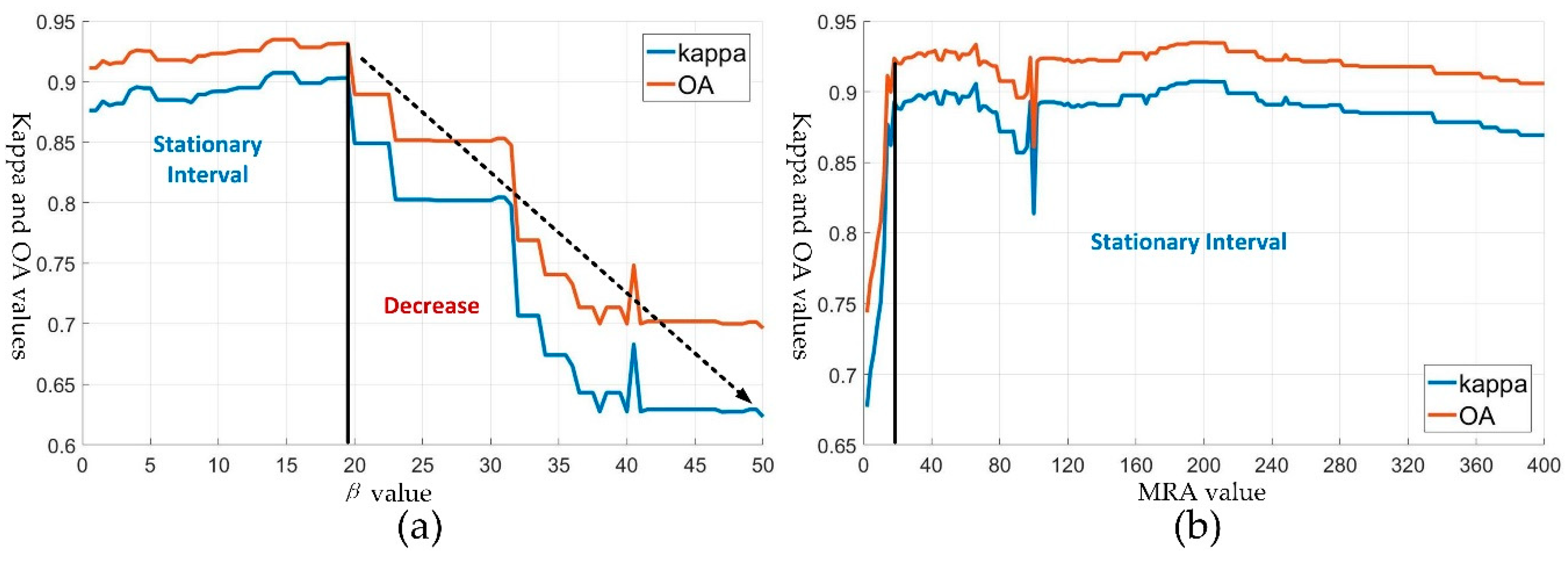
3.1. Parameter Settings of the OMRF-AP
3.2. Segmentation Experiments
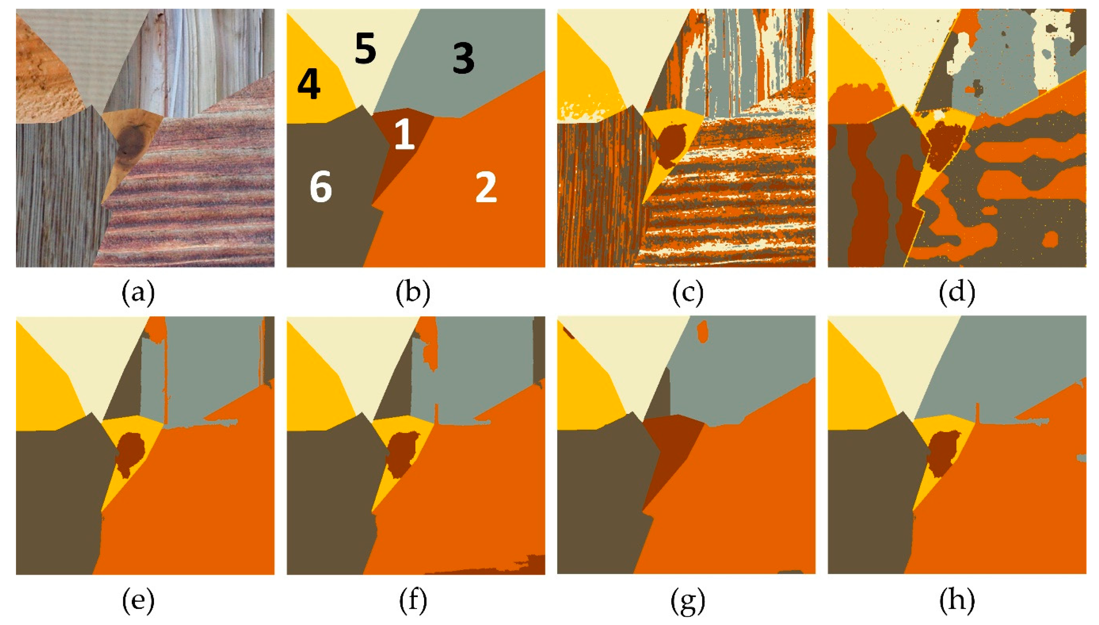
3.2.1. Segmentation of Texture Images
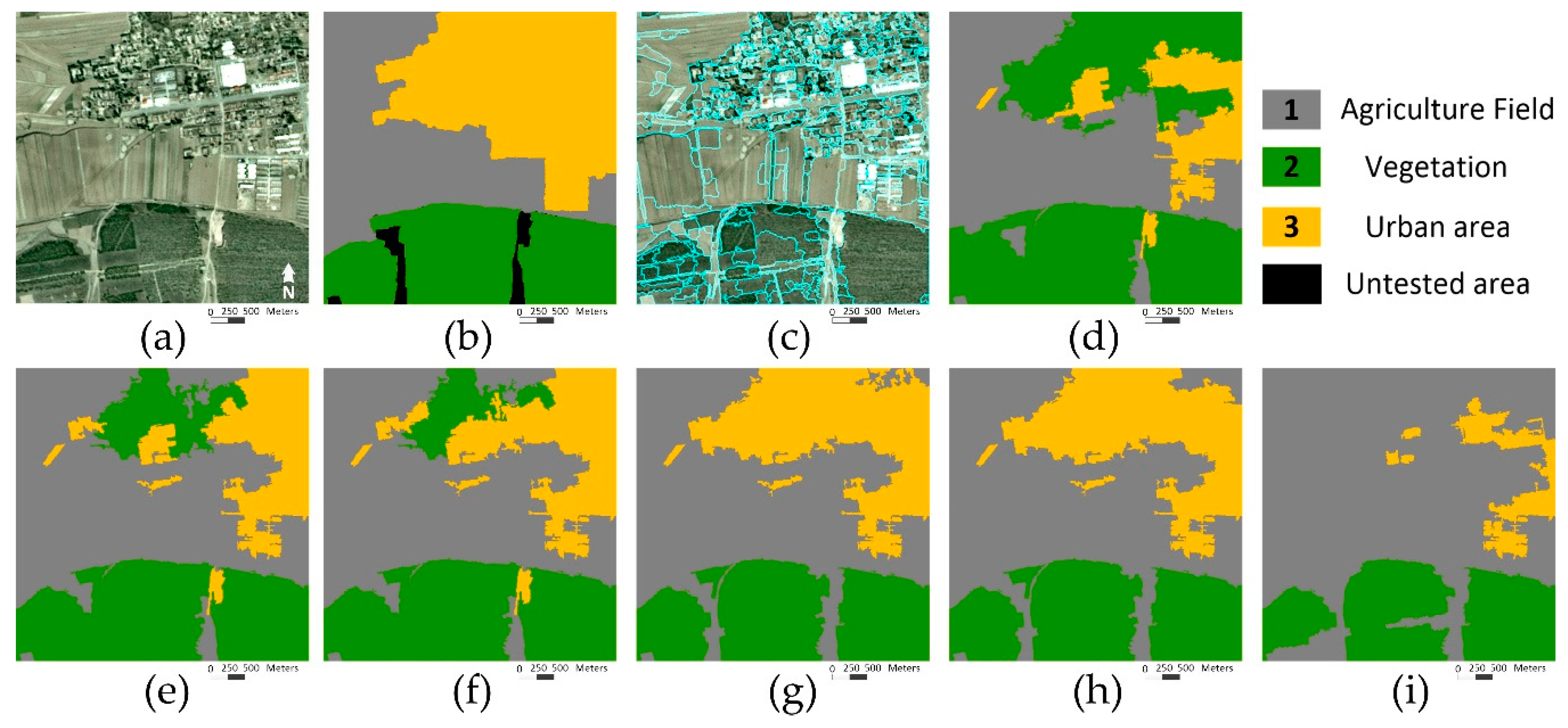
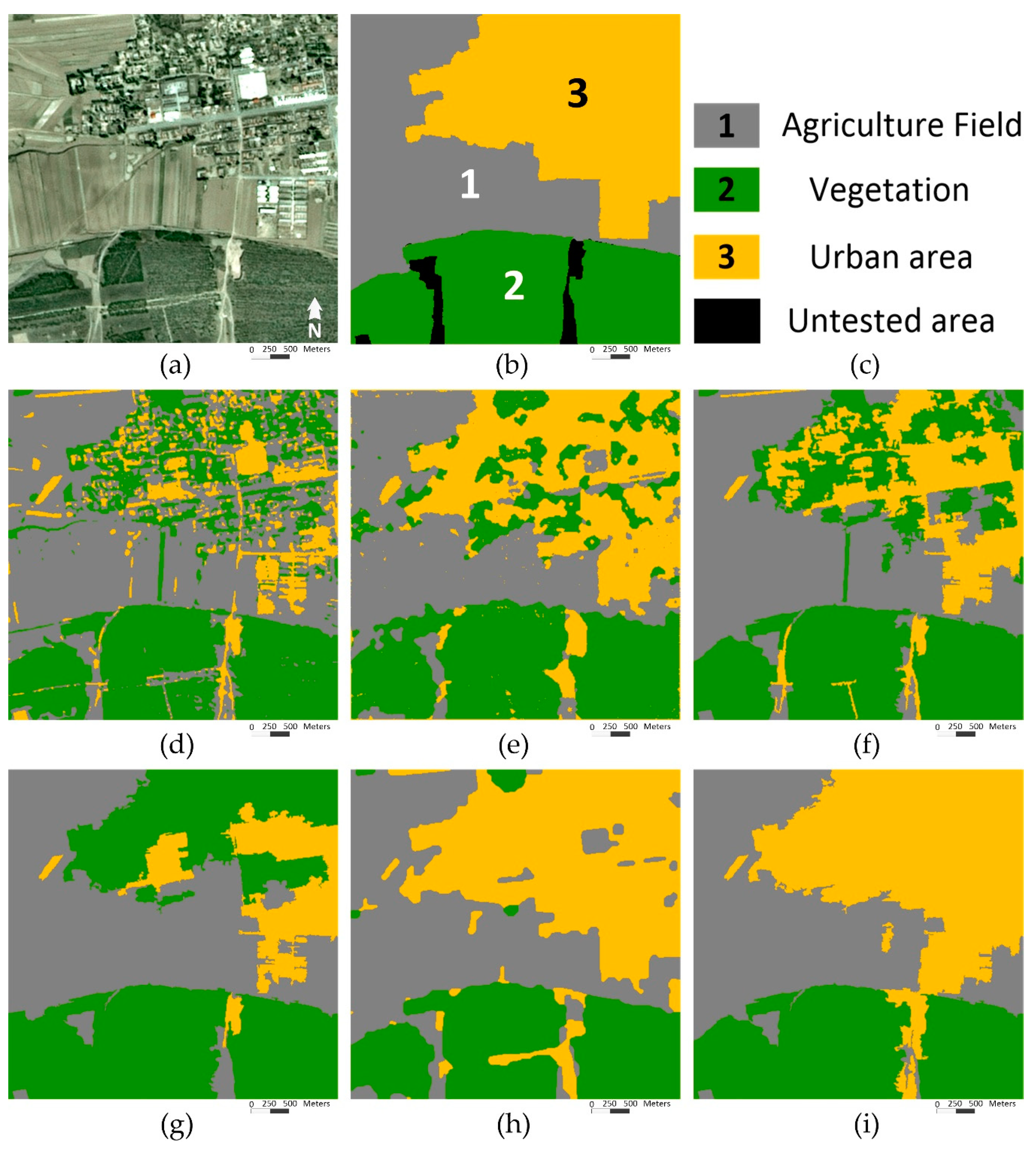
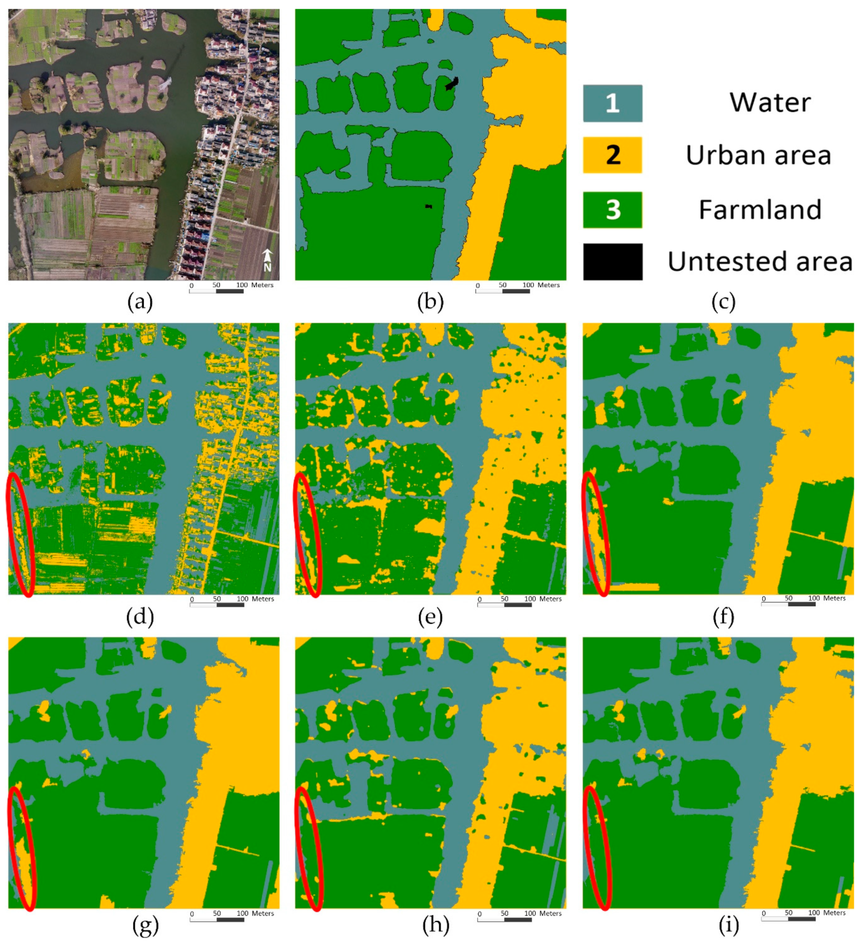
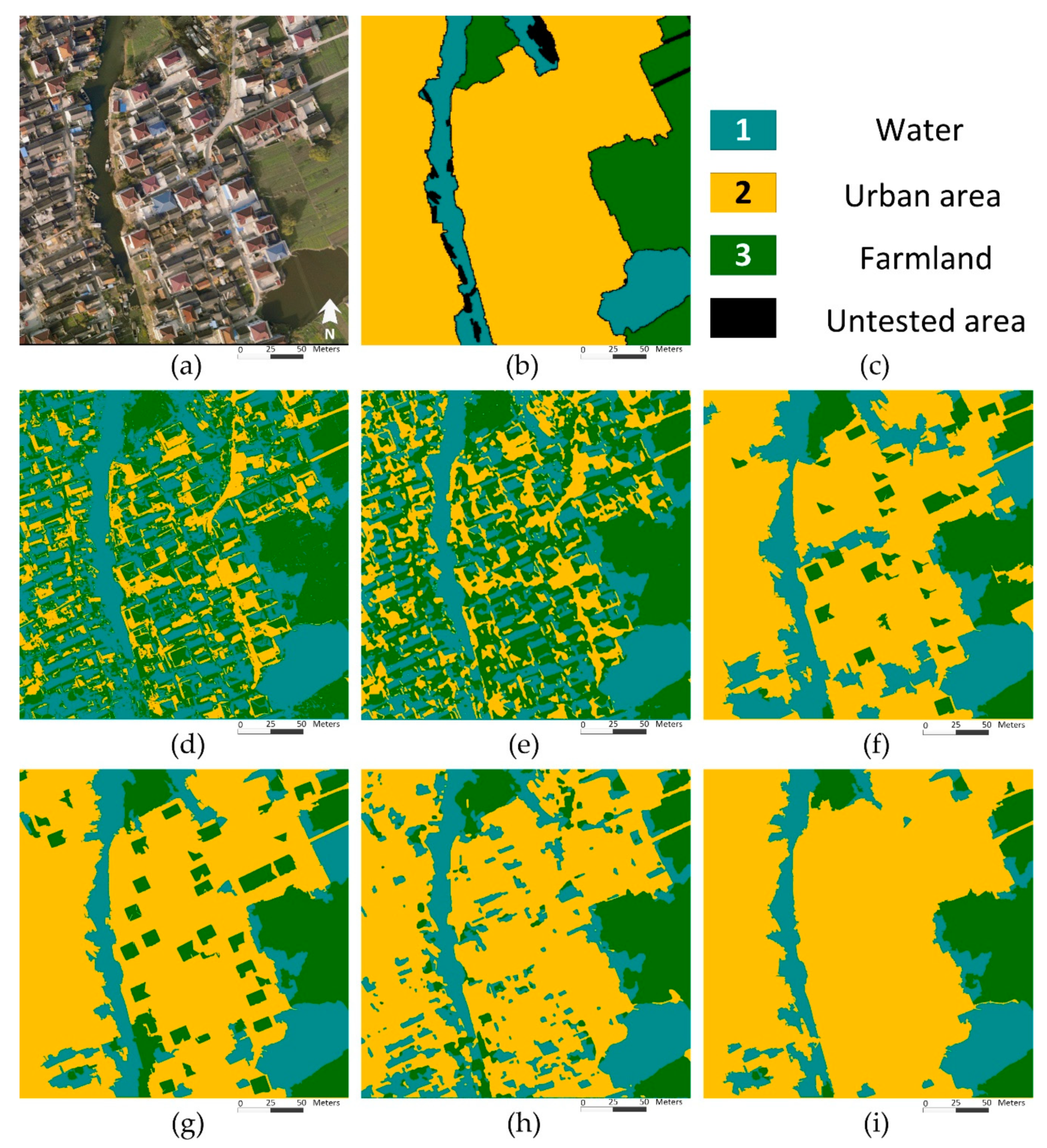
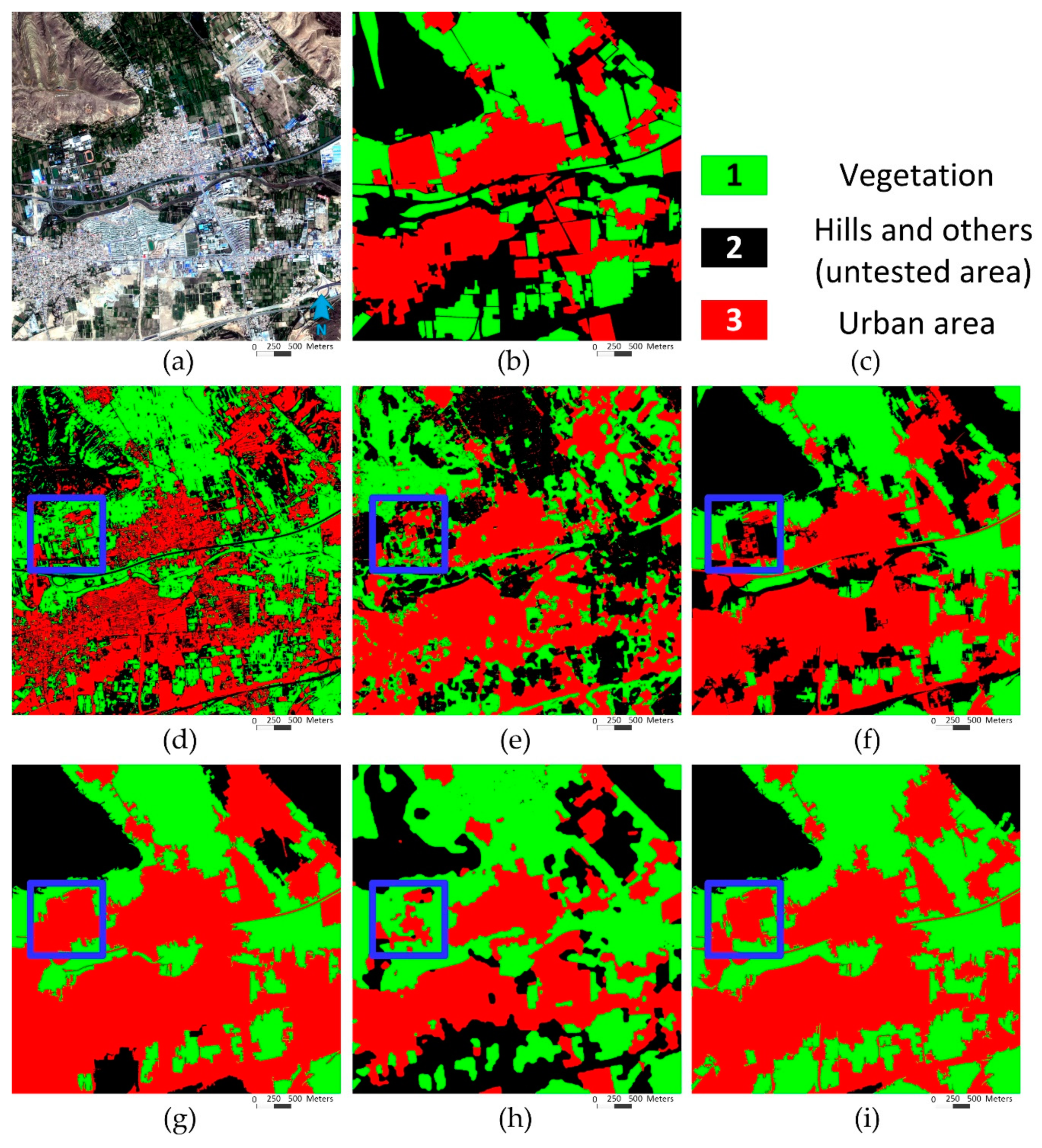
3.2.2. Segmentation of Remote Sensing Images
3.3. Post-Processing with Pixel-Based MRF
3.4. Computational Time
4. Discussion
5. Conclusions
Supplementary Materials
Author Contributions
Funding
Acknowledgments
Conflicts of Interest
References
- Jain, A.K.; Murty, M.N.; Flynn, P.J. Data clustering: A review. ACM Comptu. Surv. 1999, 31, 264–323. [Google Scholar] [CrossRef]
- Kanungo, T.; Mount, D.M.; Netanyahu, N.S.; Piatko, C.D.; Silverman, R.; Wu, A.Y. An efficient k-means clustering algorithm: Analysis and implementation. IEEE Trans. Pattern Anal. Mach. Intell. 2002, 24, 881–892. [Google Scholar] [CrossRef]
- Liu, G.Y.; Zhang, Y.; Wang, A.M. Image Fuzzy Clustering Based on the Region-Level Markov Random Field Model. IEEE Geosci. Remote Sens. Lett. 2015, 12, 1770–1774. [Google Scholar]
- Zhao, Y.; Yuan, Y.; Wang, Q. Fast Spectral Clustering for Unsupervised Hyperspectral Image Classification. Remote Sens. 2019, 11, 399. [Google Scholar] [CrossRef]
- Osher, S.; Sethian, J.A. Fronts propagating with curvature dependent speed: Algorithms based on Hamilton-Jacobi formulations. J. Comput. Phys. 1988, 79, 12–49. [Google Scholar] [CrossRef]
- Ball, J.E.; Bruce, L.M. Level set hyperspectral image classification using best band analysis. IEEE Trans. Geosci. Remote Sens. 2007, 45, 3022–3027. [Google Scholar] [CrossRef]
- Ma, H.C.; Yang, Y. Two Specific multiple-level-set models for high-resolution remote-sensing image classification. IEEE Geosci. Remote Sens. Lett. 2009, 6, 558–561. [Google Scholar]
- Längkvist, M.J.; Kiselev, A.; Alirezaie, M.; Loutfi, A. Classification and Segmentation of Satellite Orthoimagery Using Convolutional Neural Networks. Remote Sens. 2016, 8, 329. [Google Scholar] [CrossRef]
- Zhao, W.; Du, S.; Emry, W.J. Object-Based Convolutional Neural Network for High-Resolution Imagery Classification. IEEE J. Sel. Top. Appl. Earth Observ. Remote Sens. 2017, 10, 3386–3396. [Google Scholar] [CrossRef]
- De, S.; Bruzzone, L.; Bhattacharya, A.A.; Bovolo, F.; Chaudhuri, S. Novel Technique Based on Deep Learning and a Synthetic Target Database for Classification of Urban Areas in PolSAR Data. IEEE J. Sel. Top. Appl. Earth Observ. Remote Sens. 2018, 11, 154–170. [Google Scholar] [CrossRef]
- Tang, X.; Zhang, X.R.; Liu, F.; Jiao, L.C. Unsupervised deep feature learning for remote sensing image retrieval. Remote Sens. 2018, 10, 1243. [Google Scholar] [CrossRef]
- Zhao, W.; Du, S.; Wang, Q.; Emery, W.J. Contextually guided very-high-resolution imagery classification with semantic segments. ISPRS J. Photogram. Remote Sens. 2017, 132, 48–60. [Google Scholar] [CrossRef]
- Li, S.Z. Markov Random Field Modeling in Computer Vision, 3rd ed.; Springer: New York, NY, USA, 2009; pp. 88–90. [Google Scholar]
- Besag, J. On the statistical analysis of dirty pictures. J. R. Stat. Soc. Ser. B 1986, 48, 259–302. [Google Scholar] [CrossRef]
- Nishii, R. A Markov random field-based approach to decision-level fusion for remote sensing image classification. IEEE Trans. Geosci. Remote Sens. 2003, 41, 2316–2319. [Google Scholar] [CrossRef]
- Feng, W.; Jia, J.; Liu, Z.Q. Self-Validated Labeling of Markov Random Fields for Image Segmentation. IEEE Trans. Image Process. 2010, 32, 1871–1887. [Google Scholar]
- Zheng, C.; Zhang, Y.; Wang, L. Semantic Segmentation of Remote Sensing Imagery Using an Object-Based Markov Random Field Model with Auxiliary Label Fields. IEEE Trans. Geosci. Remote Sens. 2017, 55, 3015–3028. [Google Scholar] [CrossRef]
- Wang, Y.; Mei, J.; Zhang, L.; Zhang, B.; Zhu, P.; Li, Y.; Li, X. Self-Supervised Feature Learning with CRF Embedding for Hyperspectral Image Classification. IEEE Trans. Geosci. Remote Sens. 2018, 57, 2628–2642. [Google Scholar] [CrossRef]
- Zheng, C.; Yao, H. Segmentation for remote-sensing imagery using the object-based Gaussian-Markov random field model with region coefficients. Int. J. Remote Sens. 2019, 40, 4441–4472. [Google Scholar] [CrossRef]
- Bouman, C.; Liu, B. Multiple resolution segmentation of textured images. IEEE Trans. Pattern Anal. Mach. Intell. 1991, 13, 99–113. [Google Scholar] [CrossRef]
- Noda, H.; Shirazi, M.N.; Kawuguchi, E. MRF-based texture segmentation using wavelet decomposed images. Pattern Recognit. 2002, 35, 771–782. [Google Scholar] [CrossRef]
- Xia, G.S.; Chu, H.; Hong, S. An Unsupervised Segmentation Method Using Markov Random Field on Region Adjacency Graph for SAR Images. In Proceedings of the 2006 CIE International Conference on Radar, Shanghai, China, 16–19 October 2016. [Google Scholar]
- Zheng, C.; Wang, L.G. Semantic Segmentation of Remote Sensing Imagery Using Object-based Markov Random Field Model with Regional Penalties. IEEE J. Sel. Top. Appl. Earth Observ. Remote Sens. 2015, 8, 1924–1935. [Google Scholar] [CrossRef]
- Zhao, L.; Wang, X.; Yao, H.; Tian, M.; Jian, Z. Power Line Extraction from Aerial Images Using Object-Based Markov Random Field with Anisotropic Weighted Penalty. IEEE Access 2019, 7, 125333–125356. [Google Scholar] [CrossRef]
- Yu, Q.; Clausi, D.A. IRGS: Image segmentation using edge penalties and region growing. IEEE Trans. Pattern Anal. Mach. Intell. 2008, 30, 2126–2139. [Google Scholar] [PubMed]
- Yu, P.; Qin, A.K.; Clausi, D.A. Unsupervised Polarimetric SAR Image Segmentation and Classification Using Region Growing with Edge Penalty. IEEE Trans. Geosci. Remote Sens. 2012, 50, 1302–1317. [Google Scholar] [CrossRef]
- Ladicky, L.; Russell, C.; Kohil, P.; Torr, P.H.S. Associative Hierarchical Random Fields. IEEE Trans. Pattern Anal. Mach. Intell. 2014, 36, 1056–1077. [Google Scholar] [CrossRef] [PubMed]
- Wang, L.G.; Huang, X.; Zheng, C.; Zhang, Y. A Markov random field integrating spectral dissimilarity and class co-occurrence dependency for remote sensing image classification optimization. ISPRS J. Photogram. Remote Sens. 2017, 128, 223–239. [Google Scholar] [CrossRef]
- Unnikrishnan, R.; Hebert, M. Measures of Similarity. In Proceedings of the 2005 Seventh IEEE Workshops on Applications of Computer Vision, Breckenridge, CO, USA, 5–7 January 2005. [Google Scholar]
- Dempster, A.P.; Laird, N.M.; Rubin, D.B. Maximum likelihood from incomplete data via the EM algorithm. J. R. Stat. Soc. Ser. B 1977, 39, 1–38. [Google Scholar]
- Derin, H.; Elliott, H. Modeling and Segmentation of Noisy and Textured Images Using Gibbs Random Fields. IEEE Trans. Pattern Anal. Mach. Intell. 1987, 9, 39–55. [Google Scholar] [CrossRef]
- Comaniciu, D.; Meer, P. Mean shift: A robust approach toward feature space analysis. IEEE Trans. Pattern Anal. Mach. Intell. 2002, 24, 603–619. [Google Scholar] [CrossRef]
- Huang, X.; Zhang, L.P. An adaptive mean-shift analysis approach for object extraction and classification from urban hyperspectral imagery. IEEE Trans. Geosci. Remote Sens. 2008, 46, 4173–4185. [Google Scholar] [CrossRef]
- The Prague Texture Segmentation Datagenerator and Benchmark. Available online: http://mosaic.utia.cas.cz/ (accessed on 8 December 2008).
- Tong, X.Y.; Xia, G.S.; Lu, Q.K.; Shen, H.F.; Li, S.Y.; You, S.C.; Zhang, L.P. Learning Transferable Deep Models for Land-Use Classification with High-Resolution Remote Sensing Images. arXiv 2018, arXiv:1807.05713. Available online: http://captain.whu.edu.cn/GID/ (accessed on 16 July 2018).
- Han, X.P.; Huang, X.; Li, J.Y.; Li, Y.S.; Yang, M.Y.; Gong, J.Y. The edge-preservation multi-classifier relearning framework for the classification of high-resolution remotely sensed imagery. ISPRS J. Photogram. Remote Sens. 2018, 138, 57–73. [Google Scholar] [CrossRef]
- Chen, X.H.; Zheng, C.; Yao, H.T.; Wang, B.X. Image segmentation using a unified Markov random field model. IET Image Process. 2017, 11, 860–869. [Google Scholar] [CrossRef]
- Lu, Q.L.; Huang, X.; Li, J.; Zhang, L.P. A Novel MRF-Based Multifeature Fusion for Classification of Remote Sensing Images. IEEE Geosci. Remote Sens. Lett. 2016, 13, 515–519. [Google Scholar] [CrossRef]


| Agriculture Fields | Vegetation | Urban | |
|---|---|---|---|
| Agriculture fields | 61303 (0.9430) | 1134 (0.0216) | 13310 (0.1908) |
| Vegetation | 3328 (0.0512) | 51334 (0.9780) | 35716 (0.5121) |
| Urban | 375 (0.0058) | 23 (0.0004) | 20723 (0.2971) |
| Agriculture Fields | Vegetation | Urban | |
|---|---|---|---|
| Agriculture fields | 63058 (0.9700) | 3085 (0.0588) | 24186 (0.3468) |
| Vegetation | 985 (0.0152) | 49406 (0.9412) | 0 (0) |
| Urban | 963 (0.0148) | 0 (0) | 45563 (0.6532) |
| Agriculture Fields | Vegetation | Urban | |
|---|---|---|---|
| Agriculture fields | 60005 (0.9231) | 542 (0.0103) | 5724 (0.0821) |
| Vegetation | 994 (0.0153) | 50311 (0.9585) | 0 (0) |
| Urban | 4007 (0.0616) | 1638 (0.0312) | 64025 (0.9179) |
| Indicator | Method | Figure 8 | Figure 9 | Figure 10 | Figure 11 | Figure 12 | Figure 13 |
|---|---|---|---|---|---|---|---|
| OA | ICM | 0.5113 | 0.5207 | 0.6635 | 0.7355 | 0.4344 | 0.6500 |
| MRMRF | 0.8783 | 0.5287 | 0.8001 | 0.8754 | 0.4618 | 0.5322 | |
| IRGS | 0.9061 | 0.9166 | 0.7649 | 0.9191 | 0.8089 | 0.7505 | |
| OMRF | 0.9375 | 0.9096 | 0.7122 | 0.9285 | 0.8354 | 0.8100 | |
| NED-MRF | 0.9955 | 0.9823 | 0.9209 | 0.9381 | 0.8297 | 0.8564 | |
| OMRF-AP | 0.9941 | 0.9668 | 0.9311 | 0.9453 | 0.9149 | 0.9120 | |
| Kappa | ICM | 0.4782 | 0.4866 | 0.5903 | 0.6572 | 0.3928 | 0.5518 |
| MRMRF | 0.8548 | 0.4989 | 0.7515 | 0.8258 | 0.4193 | 0.4322 | |
| IRGS | 0.8877 | 0.8936 | 0.7027 | 0.8820 | 0.6970 | 0.6517 | |
| OMRF | 0.9240 | 0.8857 | 0.6424 | 0.8943 | 0.7283 | 0.7139 | |
| NED-MRF | 0.9943 | 0.9769 | 0.8889 | 0.9077 | 0.7265 | 0.7730 | |
| OMRF-AP | 0.9926 | 0.9566 | 0.9025 | 0.9170 | 0.8295 | 0.8486 |
| Indicator | Method | Figure 8 | Figure 9 | Figure 10 | Figure 11 | Figure 12 | Figure 13 |
|---|---|---|---|---|---|---|---|
| OA | IRGS | 0.9061 | 0.9166 | 0.7649 | 0.9191 | 0.8089 | 0.7505 |
| IRGS-P | 0.9153 | 0.9179 | 0.7669 | 0.9206 | 0.8097 | 0.7666 | |
| OMRF | 0.9375 | 0.9096 | 0.7122 | 0.9285 | 0.8354 | 0.8100 | |
| OMRF-P | 0.9430 | 0.9111 | 0.7165 | 0.9302 | 0.8362 | 0.8228 | |
| OMRF-AP | 0.9941 | 0.9668 | 0.9311 | 0.9453 | 0.9149 | 0.9120 | |
| OMRF-APP | 0.9998 | 0.9690 | 0.9328 | 0.9494 | 0.9165 | 0.9264 | |
| Kappa | IRGS | 0.8877 | 0.8936 | 0.7027 | 0.8820 | 0.6970 | 0.6517 |
| IRGS-P | 0.8983 | 0.8951 | 0.7035 | 0.8840 | 0.6980 | 0.6688 | |
| OMRF | 0.9240 | 0.8857 | 0.6424 | 0.8943 | 0.7283 | 0.7139 | |
| OMRF-P | 0.9305 | 0.8875 | 0.6478 | 0.8966 | 0.7292 | 0.7294 | |
| OMRF-AP | 0.9926 | 0.9566 | 0.9025 | 0.9170 | 0.8295 | 0.8486 | |
| OMRF-APP | 0.9998 | 0.9594 | 0.9048 | 0.9229 | 0.8325 | 0.8706 |
| Method | Figure 8 | Figure 9 | Figure 10 | Figure 11 | Figure 12 | Figure 13 |
|---|---|---|---|---|---|---|
| ICM | 1.19 | 2.09 | 0.62 | 29.11 | 25.11 | 10.78 |
| MRMRF | 28.24 | 28.39 | 13.06 | 407.41 | 406.61 | 134.74 |
| IRGS | 12.36 + 0.93 | 19.45 + 0.92 | 8.45 + 0.47 | 375.90 + 14.77 | 438.86 + 14.85 | 140.52 + 5.16 |
| OMRF | 17.66 + 0.93 | 7.29 + 0.95 | 5.60 + 0.46 | 230.81 + 14.68 | 416.96 + 14.90 | 121.32 + 5.16 |
| NED-MRF | 27.02 | 33.01 | 12.21 | 363.40 | 552.82 | 157.60 |
| OMRF-AP | 20.45 + 0.93 | 7.34 + 0.93 | 7.58 + 0.46 | 232.70 + 14.74 | 376.86 + 14.85 | 80.06 + 5.23 |
© 2019 by the authors. Licensee MDPI, Basel, Switzerland. This article is an open access article distributed under the terms and conditions of the Creative Commons Attribution (CC BY) license (http://creativecommons.org/licenses/by/4.0/).
Share and Cite
Zheng, C.; Pan, X.; Chen, X.; Yang, X.; Xin, X.; Su, L. An Object-Based Markov Random Field Model with Anisotropic Penalty for Semantic Segmentation of High Spatial Resolution Remote Sensing Imagery. Remote Sens. 2019, 11, 2878. https://doi.org/10.3390/rs11232878
Zheng C, Pan X, Chen X, Yang X, Xin X, Su L. An Object-Based Markov Random Field Model with Anisotropic Penalty for Semantic Segmentation of High Spatial Resolution Remote Sensing Imagery. Remote Sensing. 2019; 11(23):2878. https://doi.org/10.3390/rs11232878
Chicago/Turabian StyleZheng, Chen, Xinxin Pan, Xiaohui Chen, Xiaohui Yang, Xin Xin, and Limin Su. 2019. "An Object-Based Markov Random Field Model with Anisotropic Penalty for Semantic Segmentation of High Spatial Resolution Remote Sensing Imagery" Remote Sensing 11, no. 23: 2878. https://doi.org/10.3390/rs11232878
APA StyleZheng, C., Pan, X., Chen, X., Yang, X., Xin, X., & Su, L. (2019). An Object-Based Markov Random Field Model with Anisotropic Penalty for Semantic Segmentation of High Spatial Resolution Remote Sensing Imagery. Remote Sensing, 11(23), 2878. https://doi.org/10.3390/rs11232878