Article

Lane-Level Road Extraction from High-Resolution Optical Satellite Images

School of Geomatics, Liaoning Technical University, Fuxin 12300, China
*
Author to whom correspondence should be addressed.
Remote Sens. 2019, 11(22), 2672; https://doi.org/10.3390/rs11222672
Submission received: 24 October 2019 / Revised: 14 November 2019 / Accepted: 14 November 2019 / Published: 15 November 2019

Abstract

:
High-quality updates of road information play an important role in smart city planning, sustainable urban expansion, vehicle management, urban planning, traffic navigation, public health and other fields. However, due to interference from road geometry and texture noise, it is difficult to avoid the decline of automation while accurately extracting roads. Therefore, we propose a high-resolution optical satellite image lane-level road extraction method. First, from the perspective of template matching and considering road characteristics and relevant semantic relations, an adaptive correction model, an MLSOH (multi-scale line segment orientation histogram) descriptor, a sector descriptor, and a multiangle beamlet descriptor are proposed to solve the interference from geometry and texture noise in road template matching and tracking. Second, based on refined lane-level tracking, single-lane and double-lane road-tracking modes are designed to extract single-lane and double-lane roads, respectively. In this paper, Pleiades satellite and GF-2 images are selected to set up different scenarios for urban and rural areas. Experiments are carried out on the phenomena that restrict road extraction, such as tree occlusion, building shadow occlusion, road bending, and road boundary blurring. Compared with other methods, the proposed method not only ensures the accuracy of lane-level road extraction but also greatly improves the automation of road extraction.

Graphical Abstract

1. Introduction

In recent years, the extraction of roads from remote-sensing images has gradually become the main way to update road information. Since the 1970s, the international academic community and related fields have conducted in-depth research on the construction of road extraction models from different perspectives [1]. According to differences in image processing primitives, the existing road extraction methods can be divided into global matching methods and local analysis methods.
The global matching methods usually take the whole image as the processing unit, construct a model or sample set that conforms to the road characteristics, and analyze the road by function judgment. The most classical global matching method is the object-oriented method [2]. In this method, roads are regarded as region units with spectral textural shape similarities that are segmented according to rules and extracted by classification and post-processing. Segmentation is the core of this type of method. Commonly used segmentation models include threshold segmentation [3], multi-scale segmentation [4,5], fuzzy C-means [6], graph segmentation [7], edge segmentation [8], and the ISODATA algorithm [9]. For example, Maboudi et al. [4] applied multi-scale models combining color and shape information to segment images; classified the segmentation units based on structural, spectral, and textural characteristics; and applied the tensor voting method to connect road fractures. In general, this type of method has been applied in eCognition software and has achieved good road extraction effects in regions with small spectral texture changes. However, because the processing steps of this method have the basic sequence of segmentation, classification, and post-processing, when local deformation causes the segmentation unit to be over-segmented, the lack of an effective feedback mechanism will inevitably lead to misclassification of the segmentation unit, which reduces the accuracy of the road extraction.
Since 2012, scholars have introduced deep learning methods into the field of road extraction [10,11,12]. Deep learning can effectively solve the occlusion problem in the road extraction process by training a sample set of similar images [12]. However, deep learning methods are often affected by the number of sample sets and the depth and width of the network structure. In the process of network forward propagation, the feature resolution is often reduced, which leads to a significant reduction in the accuracy of road recognition [13]. Therefore, traditional methods such as unsupervised learning [12], the refinement method [11], geometric analysis [10], the level set method [14], and other methods [15,16,17] are also used in the post-processing optimization stage of deep learning. Although the deep learning method has the advantages of high generalization and automation, a good sample set is critical for achieving good results, and samples require a high amount of manual processing. Solving the problem of sample set automatic processing is a bottleneck in the application of deep learning methods.
The local analysis method takes the local image as the processing unit and extracts the roads through local growth or judgment according to a certain road geometric texture constraint principle. The local image judgment extraction method incorporates prior road knowledge, such as vector data [18,19], GPS data [20,21], DSM data (Digital Surface Model) [22,23], and OSM data (Open Street Map) [24], and focuses on the establishment of a hypothesis-testing model combining knowledge with image features to extract roads. It can also be considered that roads have long and narrow geometric characteristics, and the parallel edges [25,26], line segments [27,28], and path morphology [29] are used for road extraction. Notably, these methods have high restrictions on road curvature and road image edges; thus, it is difficult to meet their requirements with some roads, such as curved roads, roads with weak edges, and occluded roads.
In the road local area growth approach, the template-matching method is commonly used, which needs artificially input initial information, sets similarity rules, and uses the textural and topological features of local road images as the main driving factors. When the local image information matches the proposed rules, ground objects are decoded and recognized. According to this concept, templates can generally be divided into variable templates and rule templates. Commonly used variable templates include dynamic contour models [30,31,32,33] and level set models [30]. Rule templates include profile templates [34,35], rectangular templates [36], and T-shaped templates [37]. For example, Zhang et al. [38] manually input three points on both sides of a road, constructed a rectangular template and input direction parameter information, used the gray difference and Euclidean distance as the similarity measure to determine the best tracking results, and completed the extraction of the road network using the iterative method. Although the template-matching algorithm has high accuracy, it cannot make full use of image structure information, which leads to a low degree of automation.
As a typical human-computer interactive road extraction method, the template-matching method has the advantage of high accuracy in road extraction and has been applied in commercial software such as ERDAS EasyTrace, Feature Analyst, and EasyFeature. However, due to the influence of the road geometry and texture noise, this method still has a low degree of automation. Therefore, lane-level road extraction from high-resolution optical satellite images is proposed. This method uses an adaptive correction model, an MLSOH descriptor (multi-scale line segmentation orientation histogram descriptor), a sector descriptor and a multiangle beamlet descriptor to achieve road matching and analysis. According to double-lane and single-lane tracking mechanisms, tracking points are obtained. This method improves the automation while ensuring the accuracy of road network extraction. In the case of ensuring the accuracy of road network extraction, the degree of automation of the algorithm is improved by reducing the degree of human participation. The main contributions of the proposed method are summarized as follows:
(1) Adaptive correction model: According to the concept of internal road homogeneity, this paper performs adaptive correction through the regional gradient constraint method, automatically obtains initial road width information, and updates the positions of manually input points and tracking points.
(2) MLSOH descriptor: Starting from the semantic relationship between roads and related objects—that is, according to the principle that the edge directions of roads, motor vehicles, buildings, isolation zones, traffic indication lines, and other objects in the road buffer zone are close to the tracking directions—this paper proposes MLSOH descriptor. The descriptor can expand the perception ability of the overall structure of the road to predict the tracking direction more accurately when the area of the matching template is determined.
(3) Sector descriptor: According to the homogeneity of the road texture and the heterogeneity of road and non-road mixed areas, the optimal road point is determined. This descriptor ensures that the matching and tracking process does not shift and reduces the interference of adjacent similar objects in road extraction when the geometric information of the road image is not prominent and the role of the MLSOH descriptor is not obvious.
(4) Multiangle beamlet descriptor: When there is a large shadow on the road surface, the MLSOH descriptor and the sector descriptor are invalid. At this time, according to the law that local occlusion leads to the decline of the road gray level and the characteristics of local road linearization, this paper proposes a multiangle beamlet descriptor, which, when combined with the pixel shape index (PSI) model and beamlet algorithm, determines the road tracking point according to the maximum length principle.
(5) Simultaneous tracking mechanism for double-lane and single-lane roads: In the single-lane section, this paper completes road tracking through the road matching model based on a single point. In the double-lane section, this paper inputs two points at the same time to carry out synchronous tracking of different lanes. The tracking results are more stable, effectively avoiding the occurrence of tracking errors in the case of a double-lane.

2. Methodology

A flowchart of the proposed method is depicted in Figure 1. There are two main stages of the proposed method. (A) Preprocessing. This step provides basic information for matching and tracking via the following two steps: (i) line segment extraction and (ii) L0 smooth filtering. (B) Road matching and tracking. This paper first introduces four road matching models: the adaptive correction model, MLSOH descriptor, sector descriptor, and multiangle beamlet descriptor. Second, in the process of road tracking, this paper introduces two tracking modes: single-lane and double-lane.

2.1. Preprocessing

Preprocessing is used to extract line segment information from images and to enhance the homogeneity of pixel texture inside roads and the heterogeneity between road and non-road features. In this context, the preprocessing steps are independent and do not interfere with each other.

2.1.1. L0 Smoothing

Image smoothing is to remove the unimportant details in the image and only retain the significant edge part. In high-resolution images, the surface brightness of road images is not uniform. For example, with a ground sampling distance of less than 1 m, a zebra crossing, noise, and many other small details are visible (Figure 2a). These factors increase the complexity of the road surface and the difficulties of road tracking. In this paper, the L0 smoothing method from Xu et al. [39] is used to filter the original image. L0 norm can be understood as the number of non-zero elements in a vector. This method is a global smoothing filter based on sparse strategy. By controlling the number of non-zero image gradients to enhance the significant edge of the image, the global optimization of the image is achieved. In two-dimensional image representation, the gradient measurement of this method (the measurement of L0 norm of image gradient) can be expressed as:
C ( S ) = # { p | | x S p | + | y S p | }
In the formula, I represents the input image, and S represents the calculation result. #{} represents a statistical operation. The gradient of Sp is used to calculate the color difference between them and adjacent pixels in the x (horizontal) and y (vertical) directions for each pixel p.
As shown in Figure 2b, the slight noise and zebra crossing were removed, and the gray pixels of the road surface exhibit homogeneity. The contrast between the road surface and the surrounding environment was also enhanced, and the road edge information was well preserved.

2.1.2. Line Segment Extraction

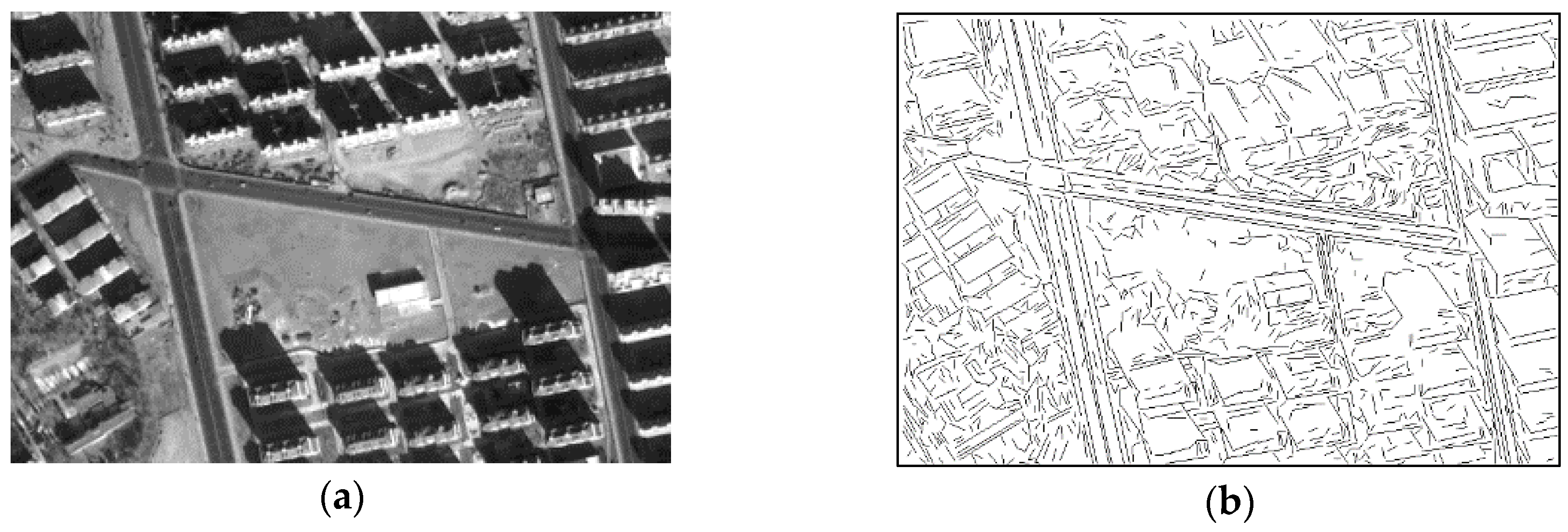
L0 filtering is a double-edged sword that can filter out noise and improve the uniformity of road pixels but can also weaken the structural information of road edges. Therefore, on the basis of the original map, this paper extracts line segments directly using the method proposed by Dai et al. [40] to ensure the accuracy of the information. First, a complete refinement algorithm targeting the Canny edge map is presented. Second, an improved chain code tracking method is proposed, and the key algorithm steps are as follows. The start points of the chain code are detected, and the dynamic main directions are set to determine the tracking directions of the chain code. The tracking of edge points inside the eight neighborhoods is preferred, but edge points outside the eight neighborhoods are tracked if there are no edge points inside the eight neighborhoods. Meanwhile, linear analysis is employed to impose dynamic constraints on the chain code. Finally, linear fitting and phase marshaling validation are applied for chain code tracking. Straight lines are output when conditions are satisfied; otherwise, the start points of the chain code are reset to extract straight lines.
As shown in Figure 3b, the road boundary and the road centerline, including the line segments extracted from the shadow portions of some buildings, had an identical or similar direction to that of the road, which made it possible to track the road based on the line segment. In the following sections, the MLSOH descriptor is constructed using line segment information (direction and length) to determine the tracking direction.

2.2. Road Matching Model

In this paper, the road matching model includes four models. First, according to the location information of reference points, an adaptive correction model is established to determine the road width and initial road center point, and the reference points are corrected simultaneously. Second, the MLSOH descriptor is used to determine the direction of the road. Finally, the sector descriptor and the multiangle beamlet descriptor are used to determine the tracking points. This section mainly introduces the principles and construction method of each descriptor. In this section, the matching point refers to the road point to be obtained by tracking, and the reference point includes both the manual input point and the known point used in the tracking process.

2.2.1. Adaptive Correction Model

In road matching processing, the positions of reference points are the basis for accurately predicting tracking points. However, in the initial and tracking stages of this method, the reference point is not guaranteed to be completely in the center of the road, which interrupts the identification of the matching point. Therefore, this paper cites the method of Tan et al. [41] and improves it to obtain the road width and correct the position of the reference point. The model establishment process is described as follows:
(1) Create a base circular template with a radius of 1 pixel centered on the reference point.
(2) Search for 8 neighborhood pixels of the reference point, centering on each pixel, to create circular templates as large as the base circular template.
(3) Compare the sums of the morphological gradients of all points in each template and calculate the morphological gradients, as shown in formula (2). Choose the template with the smallest gradient as the radius, and update the matching point to the center of the template.
G ( p ) = δ N f ( p ) ε N f ( p )
In the formula, G(p) is the morphological gradient of point p, f(p) is the gray image, δNf(p) is the morphological expansion value, εNf(p) is the morphological corrosion value, and N is the structural element.
(4) If the reference point is a manually input point, the gradient is used as a constraint, and the process proceeds to step (5). If the reference point is the matching point, the known radius of the road is selected as the constraint condition, and the process proceeds to step (6).
(5) Increase the most suitable template radius in pixels, and regard it as the basic circular template. Repeat steps (2), (3), and (4) until the sum of the gradients in the most suitable template is greater than μ (gradient threshold). At this time, the most suitable template radius is the road radius, and the center of the template is the road center after correction.
(6) Increase the most suitable template radius in pixels, and regard it as the basic circular template. Repeat steps (2), (3), and (4) until the most suitable template radius is larger than the road radius. At this point, the most suitable template center is the road center after correction.
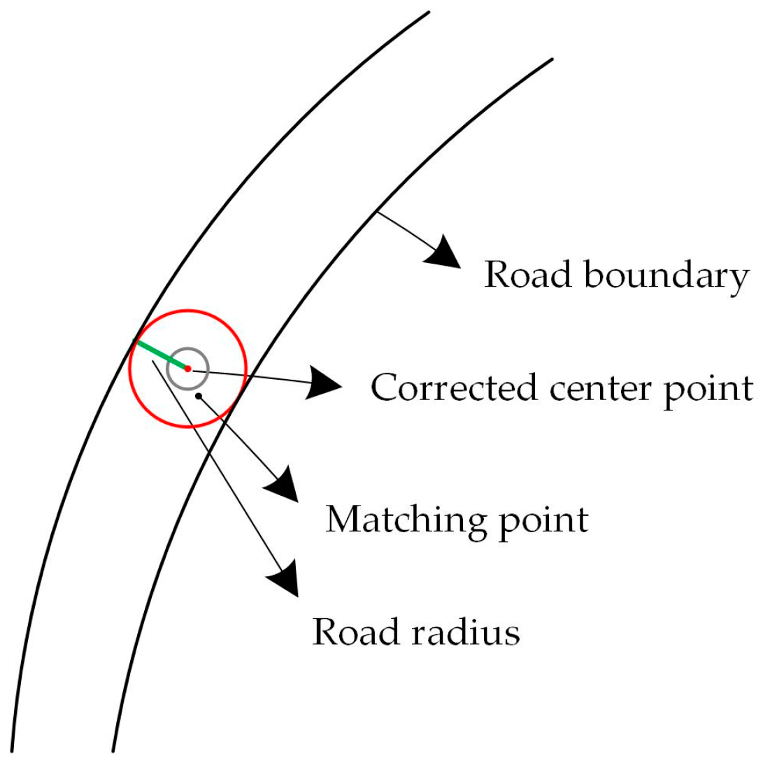
In Figure 4, the black point is the matching point, the green line is the road radius of the corresponding position, the red circle is the corrected template, and the red point is the corrected road center point.

2.2.2. MLSOH Descriptor

In real scenes of low-resolution remote sensing images, a road can be expressed based on the edge of the local road image. However, in high-resolution images, the geometric features of road edges are weakened by ground object interference, occlusion, and blurring, which makes it more difficult to depict tracking directions. This paper considers the road interior (road-marking lines, edges of mobile vehicles, central median dividers, and shaded edges of flat-roofed buildings), road edges (lined by trees and edges of parked vehicles), and objects near the road (edges of buildings) to usually have the same or a similar direction to that of the road and predicts the tracking direction by capturing the semantic relationships between shadows, trees, motor vehicles, road indicators, and other features.
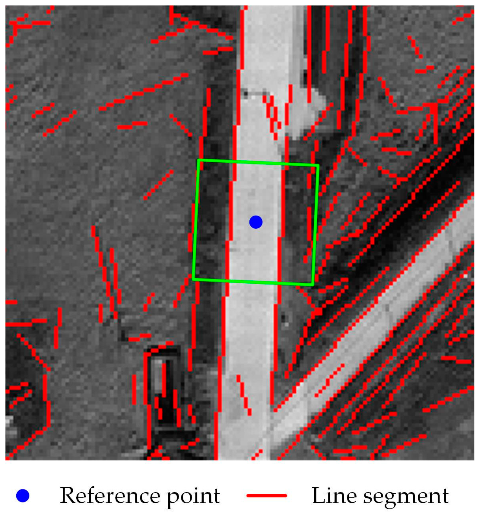
Edge information is usually expressed in two forms: edge points (Li et al. [42]) and edge lines. Edge points are a discrete form of information sensitive to local mutation points, and the regularity of edge points is difficult to characterize. A line segment is a set of regular edge points that is robust to noise and has directionality. Therefore, this paper selects the line segment as the basic expression for analyzing the direction of a road and proposes an MLSOH descriptor. As shown in Figure 5, this method centers on the reference points and takes 2 times the width of the road as the side length, establishing a rectangular search area. The road width is obtained from the adaptive correction model.
In Figure 5, the blue point is the center of the road, the green rectangle is the search area determined according to the road width, and the length and direction information of the line segment are obtained using the positional attributes of the line segment in the rectangular area; thus, the image structure information of a larger area is perceived in the local rectangular search area. At the same time, with the increase of the length of the line segment, the strength of the anti-noise ability and the coincidence with the actual object edge increase, which is conducive to improving the machine’s ability to express the image structure. The MLSOH descriptor is established as follows:
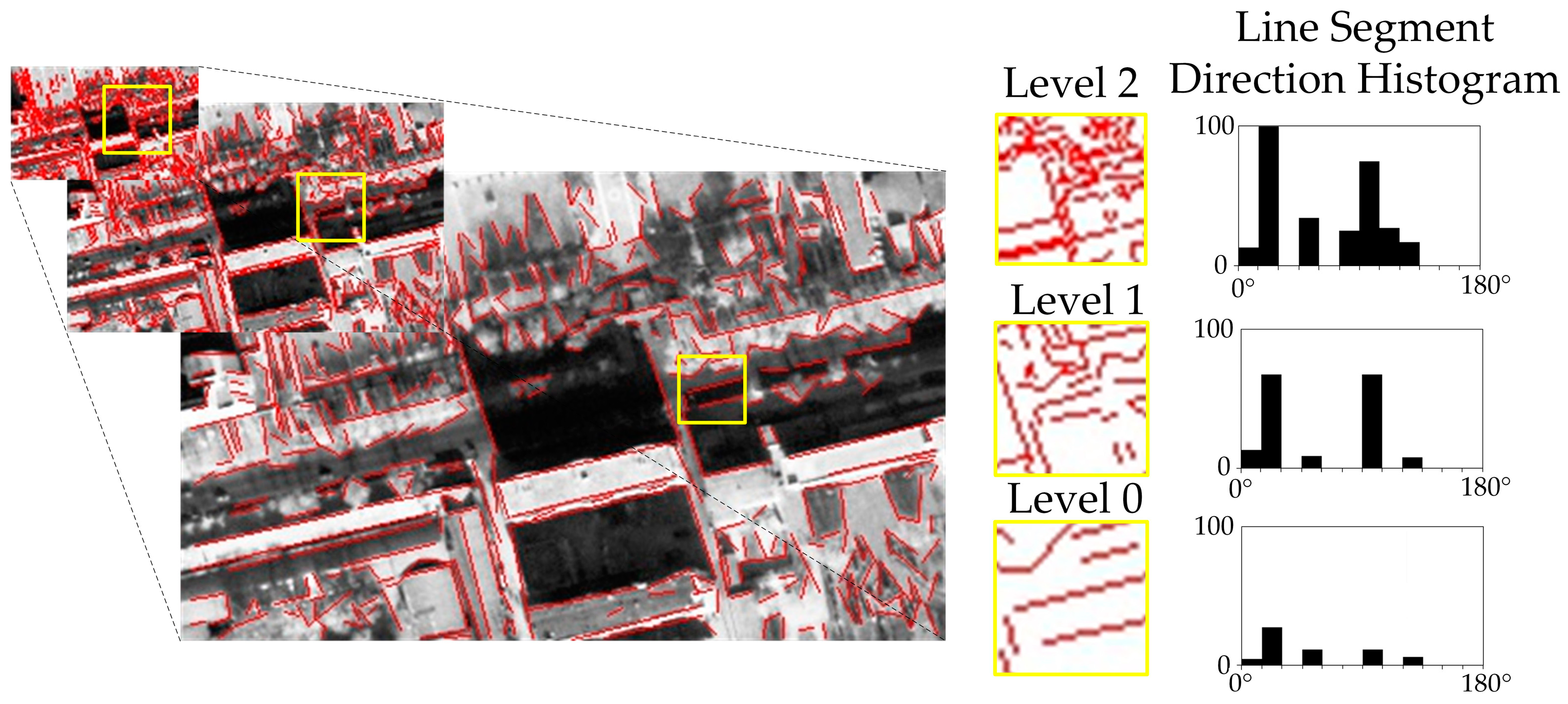
(1) A line segment pyramid is established, in which the line segment information is extracted from the original image (layer 0). The line segment endpoint coordinates are mapped to layer 1 and layer 2 by reducing the line segment coordinates by 1/2 and 1/4, respectively.
(2) A rectangular search area is created on level 0, and a search area equal to level 0 is established at the corresponding positions of level 1 and level 2.
(3) The total length of each line segment direction in each search area is separately counted, and a line direction histogram is established. The horizontal axis of this histogram shows the line direction angles, with a unit of 10° and an angle range of 0° to 180°. The vertical axis shows the cumulative value of the line length, and the unit of this axis is pixels. As shown in Figure 6, in the yellow rectangular area of level 0, the road surface is not obvious under the occlusion of building shadows and roadside features. A comparison of the histograms of level 1 and level 2 shows that the tracking direction is at a peak, which demonstrates the stability of the line direction histogram. Therefore, according to the order of layers 0-1-2, if the main peak and the sub-peak satisfy formula 3, the main peak direction is the tracking direction.
H e a p _ f H e a p _ s × β
In the formula, Heap_f is the main peak of the histogram, Heap_s is the sub-peak, and β is the scaling factor.

2.2.3. Sector Descriptor

The MLSOH descriptor determines the direction of most roads. However, on the right side of Figure 7, the structural information of the road is missing, and the segment information of the non-road area greatly interferes with the tracking process. Simply using structural information to determine tracking points will result in large errors. In this paper, based on the high homogeneity of the texture in the area corresponding to the road direction and the high heterogeneity of the mixed area of the road and other objects, the tracking direction is verified, and the tracking point is determined.
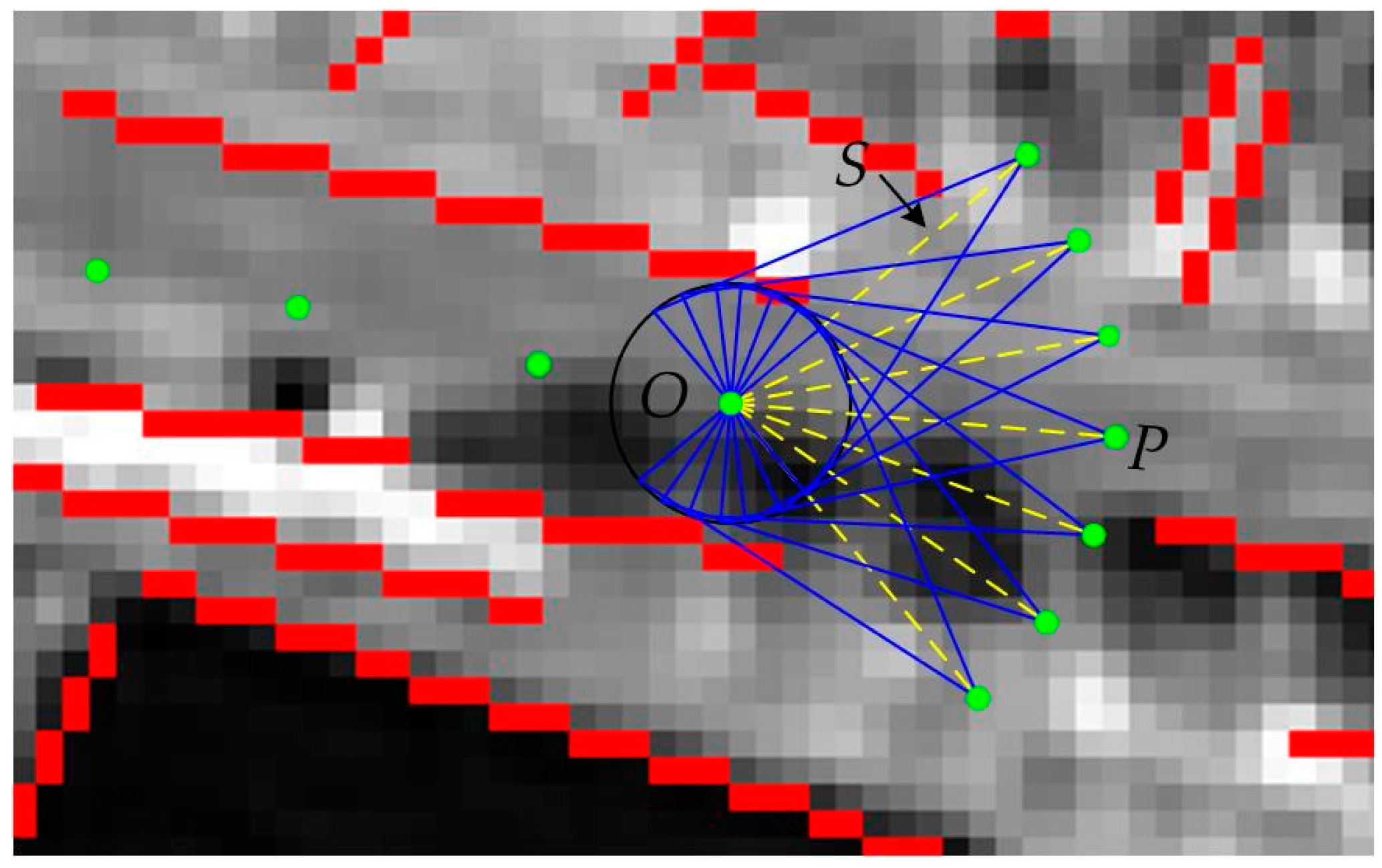
The sector is composed of 7 equally sized triangles. By analyzing the stability of the pixels in each triangle, the tracking points can be obtained. The specific process is as follows:
(1) Taking the matching point O as the origin, advance along the road with a step length of S (if the step size is too short, the calculation expense will be large, and if the step length is too long, the errors will be high; therefore, a step length equal to two times the width of the road is sufficient ensure that at least two sectors fall on the road), and reach point P (Figure 7). Establish an isosceles triangle with the diameter of the vertical tracking direction as the base and point P as the vertex. Centering on O, rotate the triangles by ±15°, ±30°, and ±45°.
(2) Record the pixel value of each triangle vertex. Then, calculate the stability (variance) and mean gray value of each triangle based on the pixel gray value, as shown below:
G r a y m e a n _ i = ( m , n ) T r i a i g r a y ( m , n ) n u m i
V a r y i = ( m , n ) T r i a i ( g r a y ( m , n ) G r a y m e a n _ i ) 2
where Varyi represents the grayscale variance of the ith triangle, Graymean_i represents the grayscale mean of the ith triangle, gray(m, n) represents the grayscale value of the image at position (m, n), (m, n) ∈Triai represents all pixel coordinates in the ith triangle, and numi represents the number of pixels in the ith triangle.
(3) Take the two triangles with the smallest Varyi, calculate the difference between Graymean_i and Grayreference (Grayreference: the mean gray value of all points to be matched) for each triangle, and take the point with a difference less than α (angle threshold) as the tracking point. If both points have a value smaller than α, the angle between the two vertices and the reference point is calculated, and the points with the smallest difference between the angle and the reference direction (Direction_reference is the average of the six recently obtained reference points, and if there are not enough reference points, this value is the average of all reference points) are taken as tracking points.

2.2.4. Beamlet Descriptor

As shown in Figure 8, the shadows of ground objects usually decrease the texture homogeneity of local pavement, thereby reducing the accuracy of the road matching model. To verify the distribution rule of the road texture near shadow areas, the horizontal axis of Figure 8b shows the distance from the current pixel to the origin, and the vertical axis shows the current pixel value. The red, green, and blue curves indicate the gray-level changes of all the pixels in the 250-pixel range in the red, green, and blue directions in Figure 8a. The curve of the shadow-covered road area presents an obviously low valley, and the distribution of the pixel values is stable and less than that of the gray reference value. Based on the texture variation characteristics and linear geometric characteristics of local roads, this paper proposes a multiangle beamlet descriptor for shadow crossing. The specific process is as follows:
(1) Adaptive adjustment of the reference point. The reference point is tracked by extending the direction of Direction_reference until the gray value of the successive pixels is less than 0.5 times the Grayreference value. This point is recorded as the origin of the multiangle beamlet descriptor. As shown in Figure 8a, OR is the reference point, and OO is the origin of the multiangle beamlet descriptor.
(2) Multidirectional ray analysis. Since the direction of the road after passing through the shadow area cannot be determined, we select Direction_reference as the reference, and rays are set every 2 degrees (experiments show that when the radius of the road is greater than or equal to 3 pixels, an interval of 2 degrees can ensure that at least two rays fall on the road and reduce the interference of noise in the experimental results) in the range of 44 degrees to the left and right, and the pixel value of each pixel through which the ray passes is taken. If the pixel value is less than or equal to γ (1.2 times Grayreference), its weighted length is increased by 1, and tracking is continued until the length of the ray is 10 times the width of the road. If the pixel value is greater than γ, the rays are interrupted.
(3) Cross shadow verification. At the end of the longest ray, tracking point verification is performed using the sector descriptors in the ray direction and the opposite direction. If the tracking point is obtained, the shadow crossing is successful; otherwise, the tracking stops.
(4) Addition of trace points to shaded areas. Starting from the origin, in the unshaded areas along the direction of the longest ray, tracking points are set at intervals of the road radius and corrected.
Figure 8c shows the shadow-crossing results. The blue points are the corrected road tracking points.

2.3. Road Tracking Progress

Taking the seed point as the starting point and tracking seed points through iteration is a method commonly used to extract tracking points by template matching. Common tracking methods include iterative interpolation and bidirectional iteration. The iterative interpolation method needs to input more than one seed point (at least two seed points for a path) and has a low degree of automation. In this paper, the bidirectional iteration method is selected to track the matching from the seed point to both ends. According to the characteristics of different roads, this paper uses two different tracking modes: single lane and double lane.

2.3.1. Single-Lane Tracking Mode

In the single-lane tracking mode, the collaboration process of different descriptors is as follows:
(1) Enter the seed point at the center of the road with a clear and unobstructed boundary.
(2) Correct seed points using the adaptive correction model, and extract the road center point of the starting position and the radius of the road.
(3) Construct the MLSOH descriptor based on the center of road. As shown in Figure 9, due to differences in the clarity of road boundaries in different sections, conduct tracking in one of the following two ways according to the ratio of the main peak to the sub-peak in the histogram
① For the layer-0 line segment histogram, if the main peak and the sub-peak satisfy formula 2, or there is only one value in the histogram, the road boundary of this section is clear, and the main peak value is the tracking direction.
② If the main peak and the sub-peak do not satisfy formula 3, the difference between the main peak and the Direction_reference value is calculated. If the difference is smaller than the threshold α, the main peak is the tracking direction. Otherwise, the sub-peak is similarly judged until the tracking direction is determined, and layer 1 and layer 2 are used to verify the direction at the same time (establish a line segment pyramid, determine the alternative tracking direction of level-1 and level-2, calculate the difference between the three tracking directions and the reference direction, and regard the angle with the minimum difference as the tracking direction). If the wireless segment is in the search area of layer 0, the tracking direction is determined by layer 1 and layer 2 in turn.
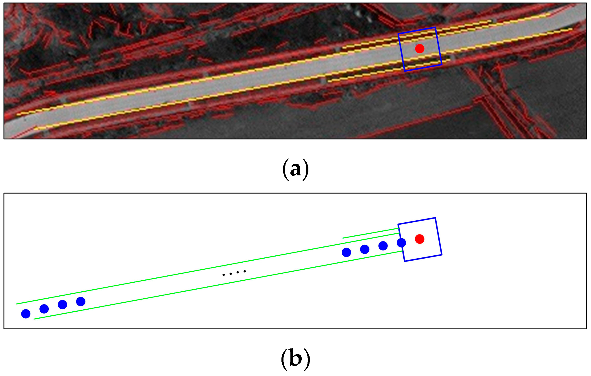
(4) For ① in (3), the tracking point is directly obtained. As shown in Figure 10, take all line segments that pass through the search area and have the same angle as the tracking direction, and calculate the length of each line segment along the tracking direction from the search area (green line segment in Figure 10b). Depending on the length of the line segment, we get the tracking points in two ways: For the line segments with a length greater than or equal to 5 times the width of the road (empirical threshold), based on the reference point, set a tracking point (blue point in Figure 10b) every other road width along the tracking direction, and stop when the distance between the last tracking point and the reference point is greater than the length of the line segment, and then proceed to step (7). Otherwise (the length of the line segment is less than 5 times the road width, or if ② in (3) occurs), proceed to step (5).
(5) Taking the current matching point as the origin, construct the sector descriptor along the tracking direction. If there are more than or equal to three triangular vertex pixels in the sector descriptor with a gray value less than or equal to 0.5 times Grayreference, the front is a suspected shadow area. Increase the step S by r (road radius) and rebuild the sector descriptor. If there are still more than 3 triangle vertices, the pixel gray value is less than or equal to 0.5 times Grayreference, and it is recognized that there are shadows ahead; therefore, enter the cross-shadowing step (6). Otherwise, the tracking point is determined directly using the original sector descriptor. If the tracking point cannot be obtained, increase the step S by the road width unit, and reconstruct the sector descriptor (in a cycle, this operation can only be carried out twice, and if the tracking point is still not available, the tracking stops), and the tracking point is determined. Proceed to step (7).
(6) Use the multiangle beamlet descriptor to cross the shadow and determine the tracking points.
(7) Use the adaptive correction model to correct the tracking points, and at the same time, calculate whether the difference between the angle between the tracking point and the reference point after correction and Direction_reference is less than α. If the condition is not satisfied, increase the step S in the unit of the road width, and reconstruct the sector descriptor to determine the tracking point (in a cycle, this operation can only be carried out twice, and if the tracking point is still not available, the tracking stops). Otherwise, keep the tracking point and update Direction_reference.
(8) Repeat steps (3) to (7) until the image boundary or the end of the road is encountered. Then, stop tracking, and output the road network.

2.3.2. Double-Lane Tracking Mode

In cities, some two-way roads are separated by guardrails, barriers and other facilities. These facilities are clearly visible in high-resolution images and divide the road into two parallel roads. If such roads are tracked separately as two single lanes, it is very likely that the tracking will be disordered. Therefore, this paper introduces a double-lane simultaneous tracking mechanism to coordinate the tracking process. The double-lane tracking mode is roughly the same as the single-lane tracking mode. It is worth noting that:
(1) Since the two lanes are tracked in the same direction, the MLSOH descriptor is constructed by superimposing the information of the two lanes to determine the unified tracking direction, and then tracking is conducted along the tracking direction based on the current reference point in each lane.
(2) When the tracking direction is verified by the sector descriptor, the Varyi values are added. The two best triangles corresponding to the smallest sum of Varyi for the two roads are taken, and then, according to the characteristics of each path, the optimal candidate points are determined. If candidate points cannot be obtained from one lane, the corresponding candidate points from the other lane are mapped to this lane.
(3) After obtaining a pair of tracking points, the distance between the two points is calculated. If the distance is greater than 2 times the width of the road, the tracking points are mapped on the road with a longer distance to the other points to ensure that the double-lane tracking points are in dynamic balance.

3. Experimental Analysis and Discussion

To verify the effectiveness of the proposed method, extensive experiments on road extraction from three remote sensing images were performed. The proposed method was also compared with other methods. In this section, we will describe the experimental setup and discuss our experimental results.

3.1. Experimental Setup

3.1.1. Description of Test Images and Compared Methods

The method proposed in this paper is mainly applicable to high-resolution images with a resolution of less than 1 meter. To verify the validity of the algorithm, we selected three panchromatic images—specifically, one Pleiades satellite image and two GF2 satellite images. All data were radiation corrected, without geographic and geometric correction.
In recent years, most research on road extraction has focused on the deep learning method, which cannot be compared with the local tracking method proposed herein. This is due to inconsistencies in the research ideas between the two methods. The deep learning method is a migration learning method, which requires a large number of training data sets to be established in advance. The proposed method belongs to the traditional manual design method and does not require a large amount of prior data. And deep learning algorithms are highly automated, but less complete (usually less than 85%) [43,44,45]; the proposed algorithm needs manual participation, but the accuracy and completeness are high (both above 95%), so they cannot make a contrast. Considering the slow progress of road extraction methods based on template matching in recent years, this paper first chooses three typical template-matching methods for comparison, including the section template, T-shaped template and rectangular template. The section template selects the IMAGINE EasyTrace module in ERDAS9.2 (a remote-sensing image processing system developed by Intergraph Company, USA), and the T-shaped template [37] and rectangle template [36] are implemented using C++ language. Second, for comparison with other different kinds of methods, the classical object-oriented method was selected, which is processed by eCognition software.
To avoid the influence of subjective factors, the road width obtained by the adaptive correction model was used as the road width of the T-type template and rectangular template.

3.1.2. Parameter Settings

The proposed algorithm requires three parameters, namely, the gradient threshold μ in the adaptive correction model, the angle threshold α in the sector descriptor, and the histogram peak ratio factor β in the MLSOH descriptor. In this paper, 100 seed points are randomly selected from each image, and the reasons behind the setting of parameters are discussed.
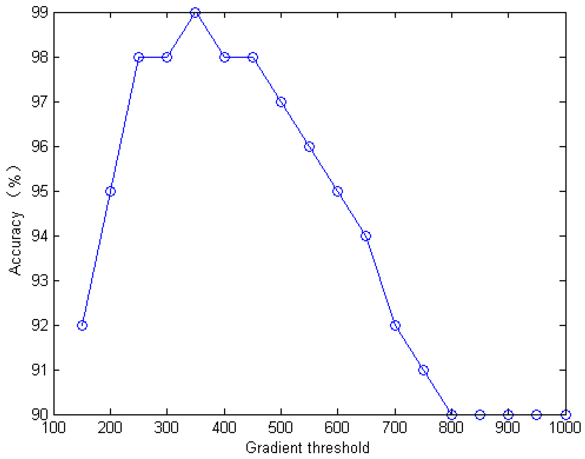
(1) Gradient threshold μ. The texture homogeneity of the filtered image was high, and the seed point was located in an area without vehicles or noise interference, so that any sudden change in the gradient was the road boundary. To obtain the optimal μ value, the road points were corrected under different gradient thresholds. At the same time, the gradient threshold was the horizontal axis, the road point correction accuracy was taken as the vertical axis, and the gradient threshold analysis chart was drawn. As shown in Figure 11, when μ was 400, the accuracy was the highest; thus, the total threshold of the gradient can be determined to be 400.
(2) Angle threshold α. In the local area, the road had linear characteristics, and the direction changed little. Even in the area with large curves, the turning angle of the road within two times the road radius did not exceed 30°. Therefore, this paper set α as 30°.
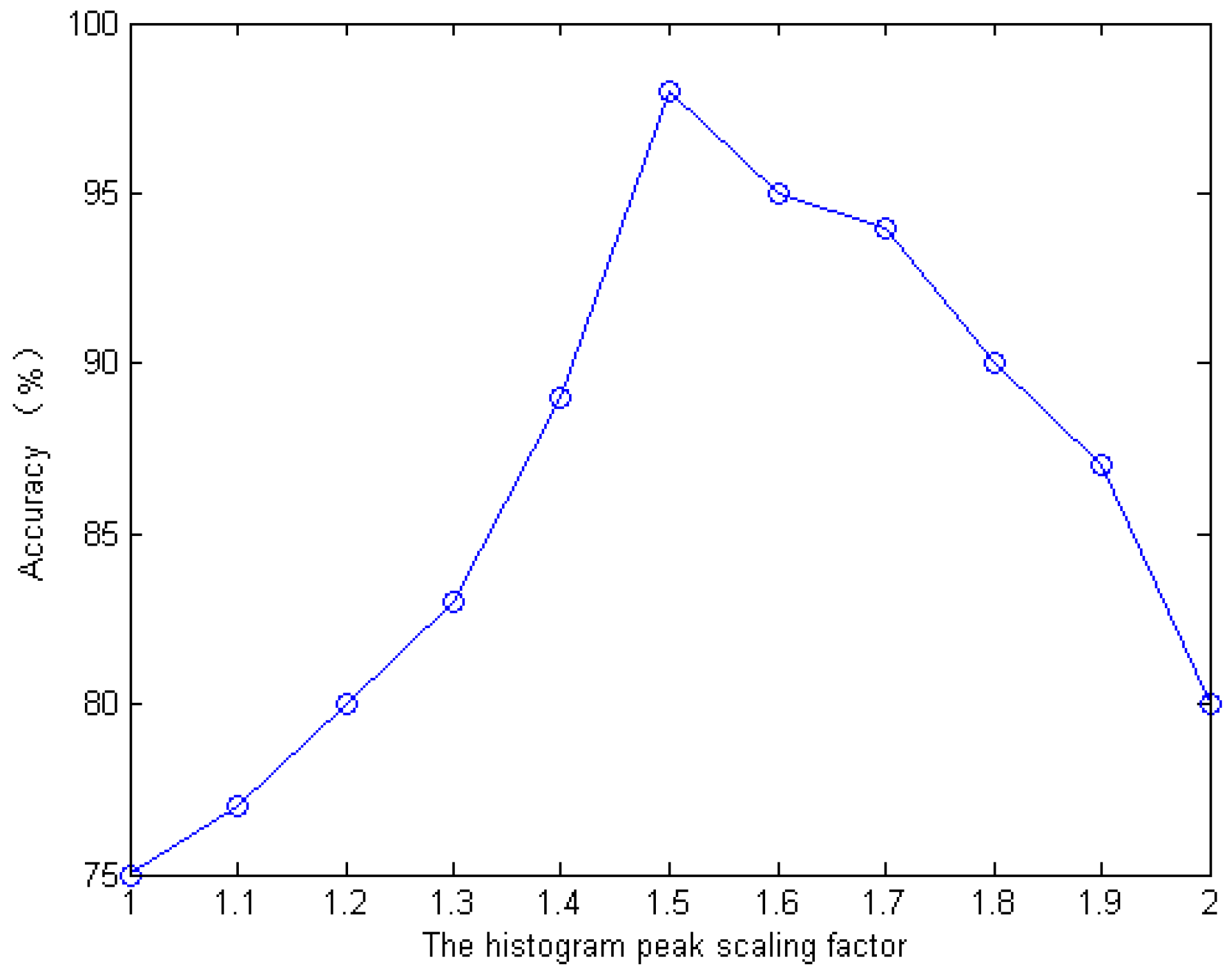
(3) In the MLSOH descriptor, the histogram peak scaling factor β is mainly used to show the relationship between the peak value of the line segment histogram and the tracking direction. Therefore, to highlight the directivity of the road edges, the MLSOH descriptor is constructed with the corrected road points as the center, and the accuracy of the road direction obtained under different β conditions is analyzed. As shown in Figure 12, the accuracy is the highest when the β value is 1.5. If the β value is too small, it can easily cause mis-extraction of the road direction in the case of multiple peaks, and if the β value is too large, the anti-noise ability of the algorithm is lowered.

3.1.3. Evaluation Metrics

The most common metrics used for evaluating an extraction method are the completeness (recall), correctness (precision), and quality (According to Wiedemann et al. [46] and Wiedemann et al. [47]). The completeness of a set of predictions is the fraction of true road pixels that are correctly extracted, while the correctness is the fraction of predicted road pixels that are true road pixels. Quality is a measure of the goodness of the final result that takes into account both the completeness and correctness.
C o m p l e t e n e s s = T P T P + F N
C o r r e c t n e s s = T P T P + F P
Q u a l i t y = T P T P + F P + F N
Here, TP is the length of the correctly extracted roads, FP is the length of non-roads extracted as roads, and FN is the length of roads extracted as non-roads.

3.2. Results

3.2.1. Pleiades Satellite Data

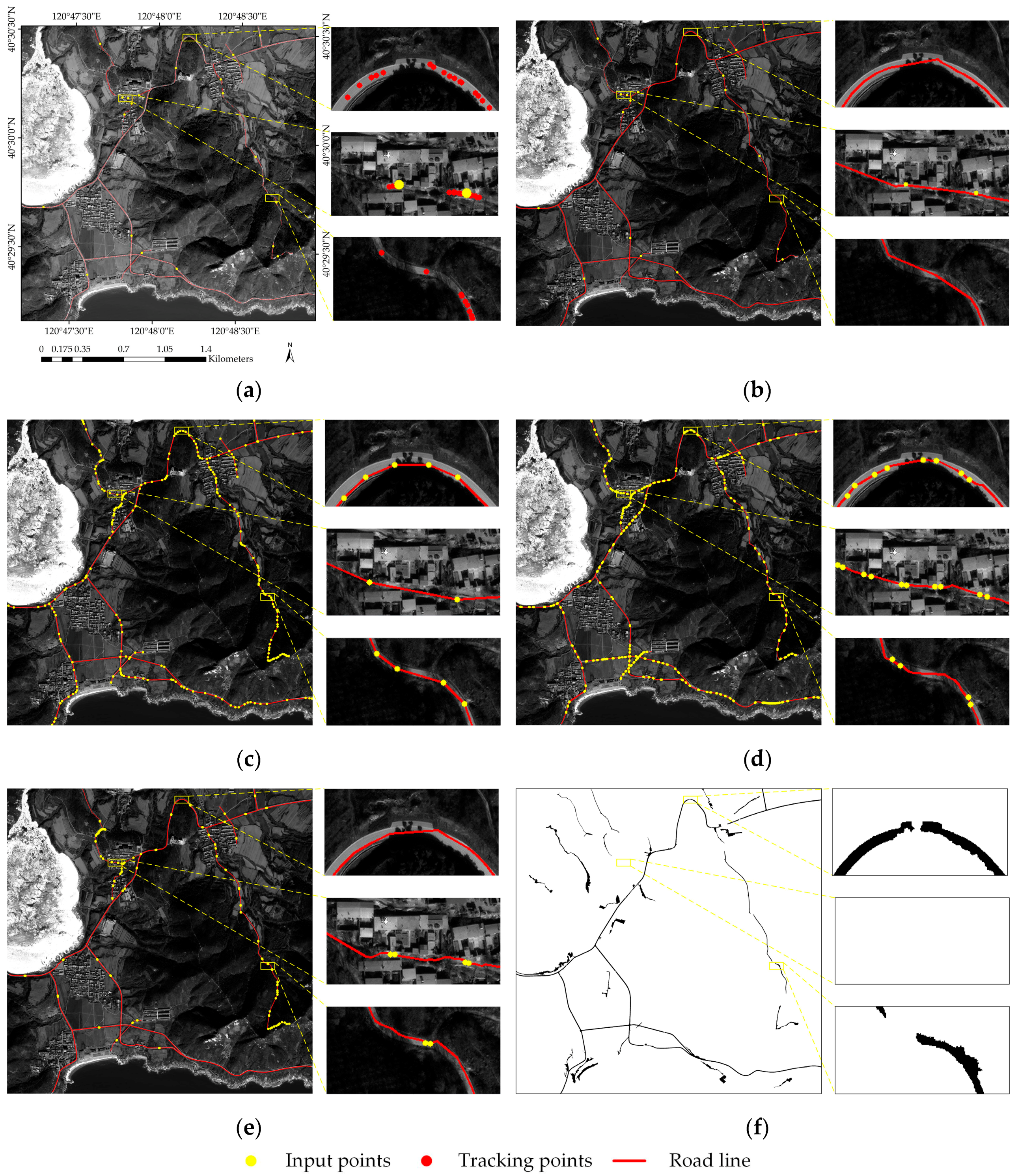
Figure 13 shows the Pleiades satellite panchromatic image covering the rural area of Chrysanthemum Island (Huludao, China), which taken at January 2016 (leaf-off) The image size is 5000 × 5000 pixels with a resolution of 0.5 m and WGS-84 coordinate system. The roads in this area are all single-lane, the internal texture of the roads in the village is very similar to that of the buildings, and the shadows of the buildings and trees cover the road surface, which increases the difficulty of tracking. The enlarged view on the right shows the local roads in three different areas. The first enlarged view on the right side of the figure shows a section with a high curvature and shadows. As can be seen, due to the interference from shadows, the structural information is not sufficient enough to predict the tracking points over a long range of phase synchronization. We used the multi-scale attributes of the MLSOH descriptor to predict the position of the road tracking points and used the sector descriptor to automatically complete the road extraction in this section according to the matching degree between the matching points and reference points. Compared with other methods, the section template and the T-type template need a large number of supplementary points. Further, due to the impact of road image texture mutation, the village roads in this region are fractured by the object-oriented method.
The second enlarged view shows the road inside a village, in which there is a high amount of noise, a complex background and a small difference between the road and the non-road areas. These factors made it difficult to identify the road even with the naked eye; therefore, the tracking effect was poor, and we could only add 2 seed points to ensure the tracking accuracy. Similarly, the other three template-matching methods also need supplementary input points to different degrees, while the object-oriented method exhibits missing extraction in this area. The third enlarged area shows a mountain road section, which has more tree shadows than the other views, and some of these shadows cover the turning position. Because the curvature is small, it meets the requirement of road linearity, and thus, we use the multiangle beamlet descriptor to extract the section automatically, whereas the other template-matching methods require manual intervention. Through the analysis of the three local road extraction scenarios, it can be seen that compared with other template-matching methods, the proposed method can complete the automatic tracking of shadows and bends. At the same time, in complex road areas within villages, the proposed method has the advantage of low manual participation.

3.2.2. GF2 Data

(1) Image One
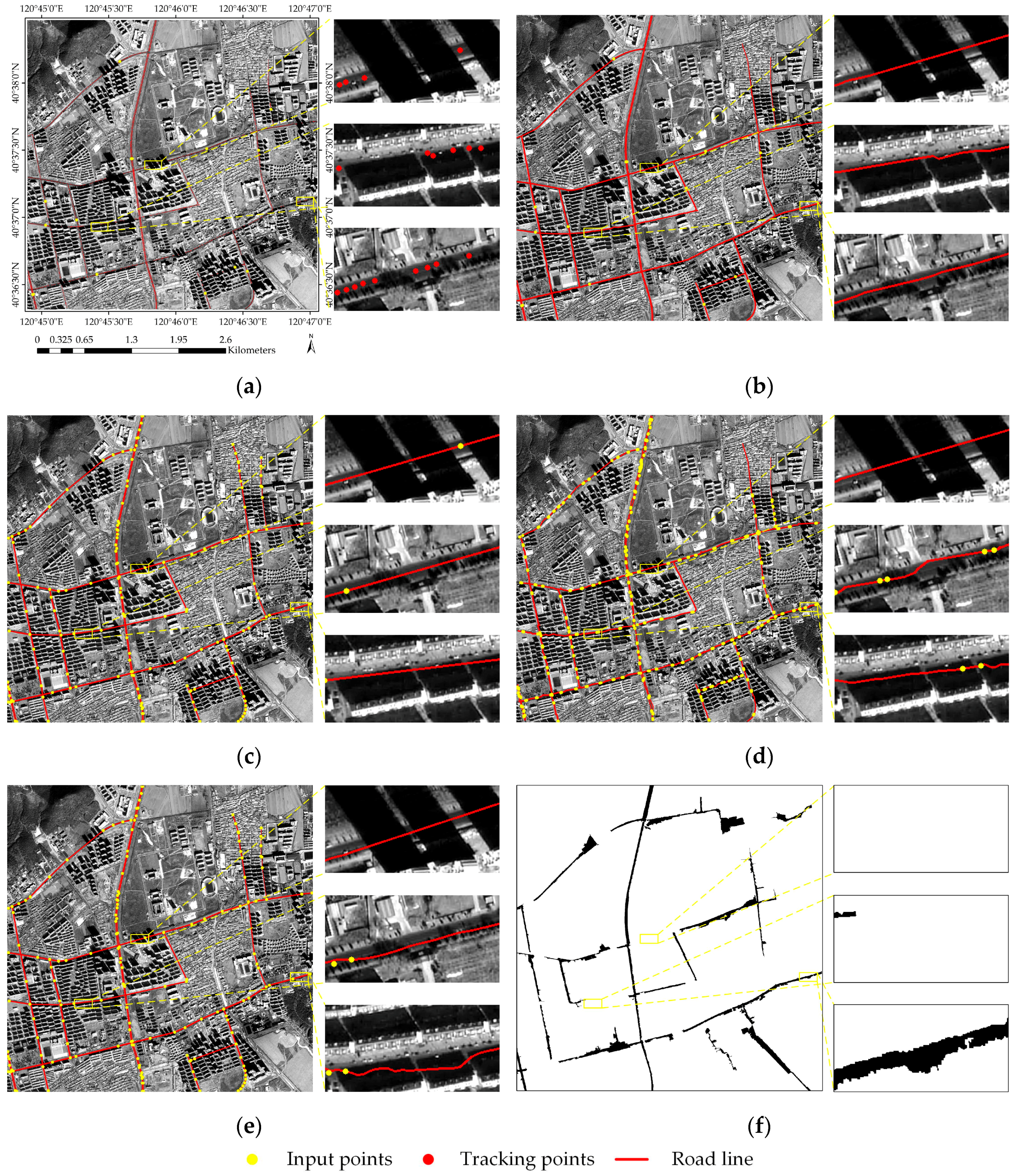
Figure 14 shows the Pleiades satellite panchromatic image covering the urban area of Huludao, China, taken in July 2015 (leaf-on). The image size is 4000 × 4000 pixels with a resolution of 1m and WGS-84 coordinate system. The roads in this area are covered by a large number of shadows, and the types of shadows are various, including not only the shadows of buildings and trees but also full and partial shadows. Figure 14b shows the road extraction results of the proposed method. The first enlarged view on the right side of the road is completely covered, and the second enlarged view shows a partial shadow covering the road. Because of the abrupt change in texture similarity in the road interior caused by shadows, the profile template, T template, and rectangular template require different degrees of manual participation in the above areas, while the object-oriented method exhibits the road fracture phenomenon in this area. The rule in which the multiangle beamlet descriptor sets a ray every 2° ensures the correct selection of tracking points in sections containing such occlusions. It can automatically complete the road tracking and extraction under full and half occlusion. The third enlarged image is a road covered by tree shadows. It can be seen that because of the structural information on one side of the road, the MLSOH multi-scale attributes are used to predict the points, and sector descriptors are used to automatically determine the tracking points. The other template-matching methods need manual intervention, and the object-oriented methods face the problem of road breakage.
(2) Image Two
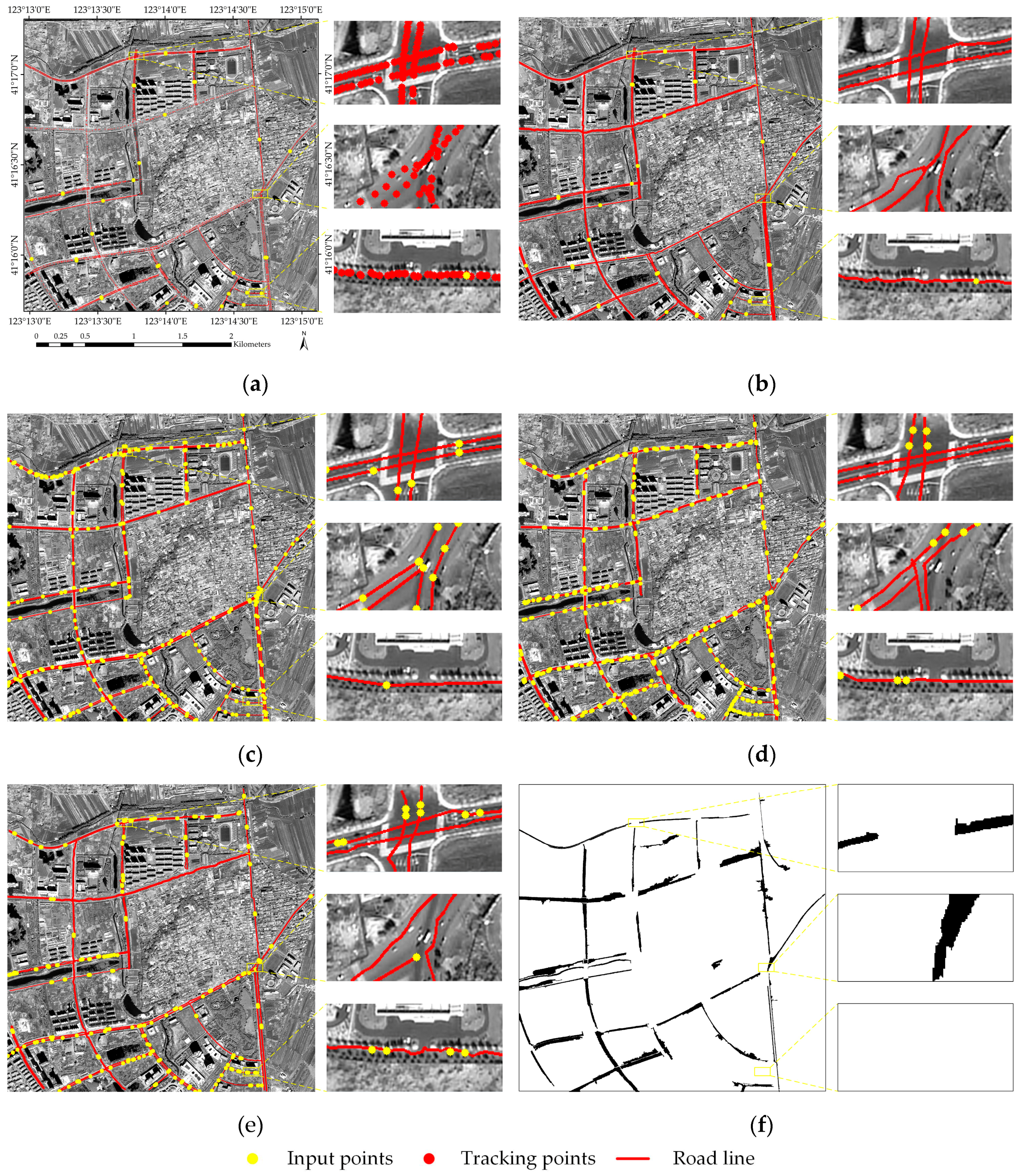
Figure 15 shows the Pleiades satellite panchromatic image covering the urban area of Shenyang, China, taken in September 2016 (leaf-on). The image size is 3000 × 3000 pixels with a resolution of 0.8 m and WGS-84 coordinate system. Furthermore, this image contains multiple double-lane roads, and the road connection mode is complex, which makes road tracking more difficult. Figure 15b shows the results of road extraction using the proposed method. The first enlarged image on the right is the area of a two-lane intersection. We can see that orderly tracking can be achieved in normal lanes. Because there is no shadow coverage on the road, the MLSOH descriptor and sector descriptor can effectively extract the lane-level roads using the two-lane tracking method. However, under the interference of a zebra crossing, the tracking points are easily mistaken when they enter the intersection due to the interference of similar objects on both sides. Therefore, the other three template-matching methods require manual intervention in this area.
In this paper, the tracking is carried out by the two-lane tracking method. According to the two-lane parallel idea, the analysis of the double-sector descriptors determines the best matching tracking points that can automatically complete the crossing of the intersection. In the second enlarged image, two double-lane roads converge into two single-lane roads. In this area, the texture of the different lanes is the same, and the road segmentation zone is not prominent, which makes this area prone to tracking errors. It can be seen that the other three template-matching methods require significant manual adjustments in this area to ensure the accuracy of the road extraction, while the object-oriented method regards it as one road. We first use the MLSOH descriptor to predict the tracking direction to ensure the accuracy of the prediction points. Second, we use the sector descriptor to confirm the prediction points to complete the accurate extraction of the complex lane-level roads in this area. In the last enlarged image, the presence of tree shadows between non-motorized lanes and motorized lanes leads to a decrease of the road texture homogeneity. Therefore, the other three template-matching methods in this section need multiple supplementary artificial input points, while only one manual input point is needed for the method proposed in this paper.

3.3. Discussion

In the tracking process, the reason for correcting the tracking point is that the tracking point determined by the sector descriptor may not be located at the center of the road, and the current tracking point is the basis for subsequent tracking. Because of the complex and changeable road conditions, the adaptive calibration model cannot ensure that the tracking point is located in the road center, but it can be located at the center of the corresponding position. At the same time, the error points can be eliminated according to the angle information to minimize the error. For the tracking fracture phenomenon in the tracking process, because the structure of the fracture area is often not clear and the occlusion is serious, we choose supplementary seed points in front of the fracture area to further ensure the accuracy of the road information acquisition and tracking. T-junctions usually connect two different roads. The algorithm can track these sections in two ways; however, research on L-turning junctions has not been carried out. Additionally, this algorithm only aims at single-lane roads and double-lane roads separated by guardrails and other facilities, while three-lane roads, four-lane roads, etc. require further study.
In this paper, the validation data is the standard road network manually sketched. We calculate the road extraction length of each algorithm in pixels. Among them, the total length of the Pleiades image road extraction is 24,792 pixels, the total length of the GF2 image with the size of 4000 × 4000 is 32,509 pixels, and the total length of the road extracted by the GF2 image with the size 3000 × 3000 is 35,253 pixels. In the local tracking road extraction method, when obstacles occur in the extraction of road tracking points, manual participation is often adopted to improve the integrity and accuracy of the road extraction; that is, the higher the manual participation, the higher the accuracy, with all reaching above 95%. Therefore, the completeness, correctness, and quality of traditional road extraction methods based on template matching are all high, and there are few differences between them. The key is the degree of manual participation. However, in the segmentation and classification process of the eCognition method, because the data processed are global images and only a few parameters need to be set, it is often difficult to fully consider changes in roads in different settings. Therefore, when facing occlusion and geometric texture interference, the integrity and quality of the road extraction are substantially lower than those of traditional template-matching methods. As can be seen in Table 1, Table 2 and Table 3, the comparison of the three other template matching methods shows that the proposed method not only ensures the accuracy of the road extraction but also greatly improves the automation of the road extraction. In this paper, the amount of human involvement mentioned in the paper is measured by the number of seed points. The author separately calculates the sum of the seed points needed for the road algorithm and the other three algorithms (profile template, T-template, and rectangular template) to extract the three images; the ratios are close to 1/10, 1/18, and 1/6, respectively. The proposed method is much better than the existing three template methods, and the experimental verification fully demonstrates the reliability of the proposed method.

4. Conclusions

In this paper, a road extraction method combining multiple descriptors is used for road network tracking in two different modes—single-lane and double lane—and the effectiveness of the algorithm is verified using different types of experimental data. The results show that this method has strong universality and can extract a complete road network under interference from buildings, trees, and partial or complete shadows. Compared with other methods, the proposed method has the obvious advantages of high automation and accuracy. However, there are still some areas of this method to be improved. For example, this algorithm can overcome most shadows. However, shadows located in bend positions conflict with the principle of multiangle beamlet descriptors and have not yet been studied. Determining how to cross all types of shadows will be the focus of future work. Furthermore, it is also urgent to determine how to track shaded sections under double-lane conditions, automatically identify intersections in the tracking process, and introduce the road centerline into the process of road tracking.

Author Contributions

Conceptualization, J.D. and T.Z.; data curation, R.M.; formal analysis, J.D. and T.Z.; Funding acquisition, J.D.; methodology, T.Z.; project administration, R.M.; resources, Y.Z.; software, T.Z. and W.L.; writing—original draft, T.Z.; writing—review and editing, J.D. and T.Z.

Funding

This paper was supported by National Natural Science Foundation of China (NO. 41871379); Key Natural Science Plan Fund in Liaoning Province (NO. 20170520141); Public Welfare Research Fund in Liaoning Province (NO.20170003); Key Laboratory of State Administration of Surveying, Mapping and Geographic Information (NO. 2018NGCM01); Liaoning Provincial Department of Education Project Services Local Project (NO. LJ2019FL008).

Acknowledgments

The authors wish to thank the editors and reviewers.

Conflicts of Interest

The authors declare no conflict of interest.

References

  1. Bajcsy, R.; Tavakoli, M. Computer Recognition of Roads from Satellite Pictures. IEEE Trans. Syst. Man Cybern. 1976, 6, 623–637. [Google Scholar] [CrossRef]
  2. Hofmann, P.; Blaschke, T.; Strobl, J. Quantifying the robustness of fuzzy rule sets in object-based image analysis. Int. J. Remote Sens. 2011, 32, 7359–7381. [Google Scholar] [CrossRef]
  3. Raziq, A.; Xu, A.; Li, Y. Automatic Extraction of Urban Road Centerlines from High-Resolution Satellite Imagery Using Automatic Thresholding and Morphological Operation Method. J. Geogr. Inf. Syst. 2016, 8, 517–525. [Google Scholar] [CrossRef]
  4. Maboudi, M.; Amini, J.; Hahn, M.; Saati, M. Road Network Extraction from VHR Satellite Images Using Context Aware Object Feature Integration and Tensor Voting. Remote Sens. 2016, 8, 637. [Google Scholar] [CrossRef]
  5. Maboudi, M.; Amini, J.; Hahn, M.; Saati, M. Object-based road extraction from satellite images using ant colony optimization. Int. J. Remote Sens. 2017, 38, 179–198. [Google Scholar] [CrossRef]
  6. Ameri, F.; Zoej, M.J.V. Road vectorisation from high-resolution imagery based on dynamic clustering using particle swarm optimisation. Photogramm. Rec. 2015, 30, 363–386. [Google Scholar] [CrossRef]
  7. Alshehhi, R.; Marpu, P.R. Hierarchical graph-based segmentation for extracting road networks from high-resolution satellite images. ISPRS J. Photogramm. Remote Sens. 2017, 126, 245–260. [Google Scholar] [CrossRef]
  8. Miao, Z.; Shi, W.; Zhang, H.; Wang, X. Road centerline extraction from high-resolution imagery based on shape features and multivariate adaptive regression splines. IEEE Geosci. Remote Sens. Lett. 2013, 10, 583–587. [Google Scholar] [CrossRef]
  9. Miao, Z.; Shi, W.; Gamba, P.; Li, Z. An Object-Based Method for Road Network Extraction in VHR Satellite Images. IEEE J. Sel. Top. Appl. Earth Obs. Remote Sens. 2015, 8, 4853–4862. [Google Scholar] [CrossRef]
  10. Alshehhi, R.; Marpu, P.R.; Woon, W.L.; Mura, M.D. Simultaneous extraction of roads and buildings in remote sensing imagery with convolutional neural networks. ISPRS J. Photogramm. Remote Sens. 2017, 130, 139–149. [Google Scholar] [CrossRef]
  11. Cheng, J.; Ding, W.; Ku, X.; Sun, J. Road extraction from high-resolution sar images via automatic local detecting and human-guided global tracking. Int. J. Antenn. Propag. 2014, 2012, 1497–1500. [Google Scholar] [CrossRef]
  12. Zhang, Z.; Liu, Q.; Wang, Y. Road Extraction by Deep Residual U-Net. IEEE Geosci. Remote Sens. Lett. 2018, 15, 749–753. [Google Scholar] [CrossRef]
  13. Mnih, V.; Hinton, G.E. Learning to detect roads in high-resolution aerial images. In Proceedings of the Computer Vision—ECCV, European Conference on Computer Vision, Heraklion, Crete, Greece, 5–11 September 2018; Volume 6316, pp. 210–223. [Google Scholar]
  14. Rajeswari, M.; Gurumurthy, K.S.; Omkar, S.N.; Senthilnath, J.; Reddy, L.P. Automatic road extraction using high resolution satellite images based on Level Set and Mean Shift methods. In Proceedings of the Fourth International Conference on Computing, Kanyakumari, India, 8–10 April 2011. [Google Scholar]
  15. Jiang, Y. Research on road extraction of remote sensing image based on convolutional neural network. EURASIP J. Image Video Process. 2019, 2019, 31. [Google Scholar] [CrossRef]
  16. Panboonyuen, T.; Jitkajornwanich, K.; Lawawirojwong, S.; Srestasathiern, P.; Vateekul, P. Road Segmentation of Remotely-Sensed Images Using Deep Convolutional Neural Networks with Landscape Metrics and Conditional Random Fields. Remote Sens. 2017, 9, 680. [Google Scholar] [CrossRef]
  17. Paisitkriangkrai, S.; Sherrah, J.; Janney, P.; Hengel, V.D. Effective semantic pixel labelling with convolutional networks and Conditional Random Fields. In Proceedings of the IEEE Conference on Computer Vision and Pattern Recognition Workshops, Boston, MA, USA, 7–12 June 2015. [Google Scholar]
  18. Sui, H.; Hua, L.; Gong, J. Automatic extraction of road networks from remotely sensed images based on GIS knowledge. Image Proc. Pattern Recognit. Remote Sens. 2003, 4898, 226–238. [Google Scholar]
  19. Chen, H.; Yin, L.; Ma, L. Research on road information extraction from high resolution imagery based on global precedence. In Proceedings of the 2014 Third International Workshop on Earth Observation and Remote Sensing Applications (EORSA), Changsha, China, 11–14 June 2014; pp. 151–155. [Google Scholar]
  20. Li, J.; Qin, Q.; Xie, C.; Zhao, Y. Integrated use of spatial and semantic relationships for extracting road networks from floating car data. Int. J. Appl. Earth Obs. Geoinform. 2012, 19, 238–247. [Google Scholar] [CrossRef]
  21. Cao, C.; Sun, Y. Automatic Road Centerline Extraction from Imagery Using Road GPS Data. Remote Sens. 2014, 6, 9014–9033. [Google Scholar] [CrossRef]
  22. Uemura, T.; Uchimura, K.; Koutaki, G. Road extraction in urban areas using boundary code segmentation for DSM and aerial rgb images. J. Inst. Image Electron. Eng. Jpn. 2011, 40, 74–85. [Google Scholar]
  23. Herumurti, D.; Uchimura, K.; Koutaki, G.; Uemura, T. Urban road network extraction based on zebra crossing detection from a very high resolution RGB aerial image and DSM data. In Proceedings of the International Conference on Signal-Image Technology & Internet-Based Systems, Kyoto, Japan, 2–5 December 2013; pp. 79–84. [Google Scholar]
  24. Li, Q.; Fan, H.; Luan, X.; Yang, B.; Liu, L. Polygon-based approach for extracting multilane roads from OpenStreetMap urban road networks. Int. J. Geogr. Inf. Sci. 2014, 28, 2200–2219. [Google Scholar] [CrossRef]
  25. Treash, K.; Amaratunga, K. Automatic Road Detection in Grayscale Aerial Images. J. Comput. Civ. Eng. 2000, 14, 60–69. [Google Scholar] [CrossRef]
  26. Sghaier, M.O.; Lepage, R. Road extraction from very high resolution remote sensing optical images based on texture analysis and beamlet transform. IEEE J. Sel. Top. Appl. Earth Observ. Remote Sens. 2016, 9, 1946–1958. [Google Scholar] [CrossRef]
  27. Sengupta, S.K.; Lopez, A.S.; Brase, J.M.; Paglieroni, D.W. Phase-based road detection in multi-source images. IGARSS 2004. 2004 IEEE Internat. Geosci. Remote Sens. Symp. 2004, 6, 3833–3836. [Google Scholar]
  28. Shao, Y.; Guo, B.; Hu, X.; Di, L. Application of a fast linear feature detector to road extraction from remotely sensed imagery. IEEE J. Sel. Top. Appl. Earth Observ. Remote Sens. 2011, 4, 626–631. [Google Scholar] [CrossRef]
  29. Schubert, H.; Van De Gronde, J.J.; Roerdink, J.B.T.M. Efficient Computation of Greyscale Path Openings. Math. Morphol. Theory Appl. 2016, 1, 189–202. [Google Scholar] [CrossRef]
  30. Xu, C.; Prince, J.L. Gradient vector flow: A new external force for snakes. In Proceedings of the IEEE Computer Society Conference on Computer Vision & Pattern Recognition, San Juan, PR, USA, 17–19 June 1997; pp. 66–71. [Google Scholar]
  31. Li, C.; Kao, C.-Y.; Gore, J.C.; Ding, Z. Minimization of region-scalable fitting energy for image segmentation. IEEE Trans. Image Process. 2008, 17, 1940–1949. [Google Scholar] [PubMed]
  32. Nakaguro, Y.; Makhanov, S.; Dailey, M. Numerical experiments with cooperating multiple quadratic snakes for road extraction. Int. J. Geogr. Inf. Sci. 2011, 25, 765–783. [Google Scholar] [CrossRef]
  33. Sethian, J.A. A fast marching level set method for monotonically advancing fronts. Proc. Natl. Acad. Sci. USA 1996, 93, 1591–1595. [Google Scholar] [CrossRef]
  34. Hu, X.; Zhang, Z.; Zhang, J. An approach of semi-automated road extraction from aerial images based on template matching and neural network. 2000. Available online: https://pdfs.semanticscholar.org/a5da/323a4e136db68c3400d31904545b40e50d7f.pdf (accessed on 24 October 2019).
  35. Leninisha, S.; Vani, K. Water flow based geometric active deformable model for road network. ISPRS J. Photogramm. Remote Sens. 2015, 102, 140–147. [Google Scholar] [CrossRef]
  36. Lin, X.; Zhang, J.; Liu, Z.; Shen, J.; Duan, M. Semi-automatic extraction of road networks by least squares interlaced template matching in urban areas. Int. J. Remote Sens. 2011, 32, 4943–4959. [Google Scholar] [CrossRef]
  37. Lin, X.; Liu, Z. Semi-automatic extraction of ribbon roads from high resolution remotely sensed imagery by T-shaped template matching. Geom. Inf. Sci. Wuhan Univ. 2009, 7147, 293–296. [Google Scholar]
  38. Zhang, J.; Lin, X.; Liu, Z.; Shen, J. Semi-automatic road tracking by template matching and distance transformation in urban areas. Int. J. Remote Sens. 2011, 32, 8331–8347. [Google Scholar] [CrossRef]
  39. Xu, L.; Lu, C.; Xu, Y.; Jia, J. Image smoothing via l0 gradient minimization. ACM Trans. Graph. 2010, 30, 1–12. [Google Scholar]
  40. Dai, J.; Li, Z.; Jinwei, L.I.; Fang, X. A line extraction method for chain code tracking with phase verification. Acta Geod. Geophys. 2017, 46, 218–227. [Google Scholar]
  41. Tan, R.; Wan, Y.; Yuan, F.; Li, G. Semi-automatic road extraction of high resolution remote sensing images based on circular template. Bull. Surv. Map. 2014, 10, 63–66. [Google Scholar]
  42. Li, G.; An, J.; Chen, C. Automatic Road Extraction from High-Resolution Remote Sensing Image Based on Bat Model and Mutual Information Matching. J. Comput. 2011, 6, 2417–2426. [Google Scholar] [CrossRef]
  43. Wei, Y.; Wang, Z.; Xu, M. Road Structure Refined CNN for Road Extraction in Aerial Image. IEEE Geosci. Remote Sens. Lett. 2017, 14, 1–5. [Google Scholar] [CrossRef]
  44. Xu, Y.; Xie, Z.; Feng, Y.; Chen, Z. Road Extraction from High-Resolution Remote Sensing Imagery Using Deep Learning. Remote Sens. 2018, 10, 1461. [Google Scholar] [CrossRef]
  45. Gao, L.; Song, W.; Dai, J.; Chen, Y. Road Extraction from High-Resolution Remote Sensing Imagery Using Refined Deep Residual Convolutional Neural Network. Remote Sens. 2019, 11, 552. [Google Scholar] [CrossRef] [Green Version]
  46. Wiedemann, C.; Heipke, C.; Mayer, H. Empirical evaluation of automatically extracted road axes. In Empirical Evaluation Techniques in Computer Vision; Bowyer, K., Phillips, P.J., Eds.; IEEE Computer Society Press: Los Alamitos, CA, USA, 1998; pp. 172–187. [Google Scholar]
  47. Wiedemann, C.; Ebner, H. Automatic completion and evaluation of road networks. Int. Arch. Photogramm. Remote Sens. 2000, 33, 979–986. [Google Scholar]
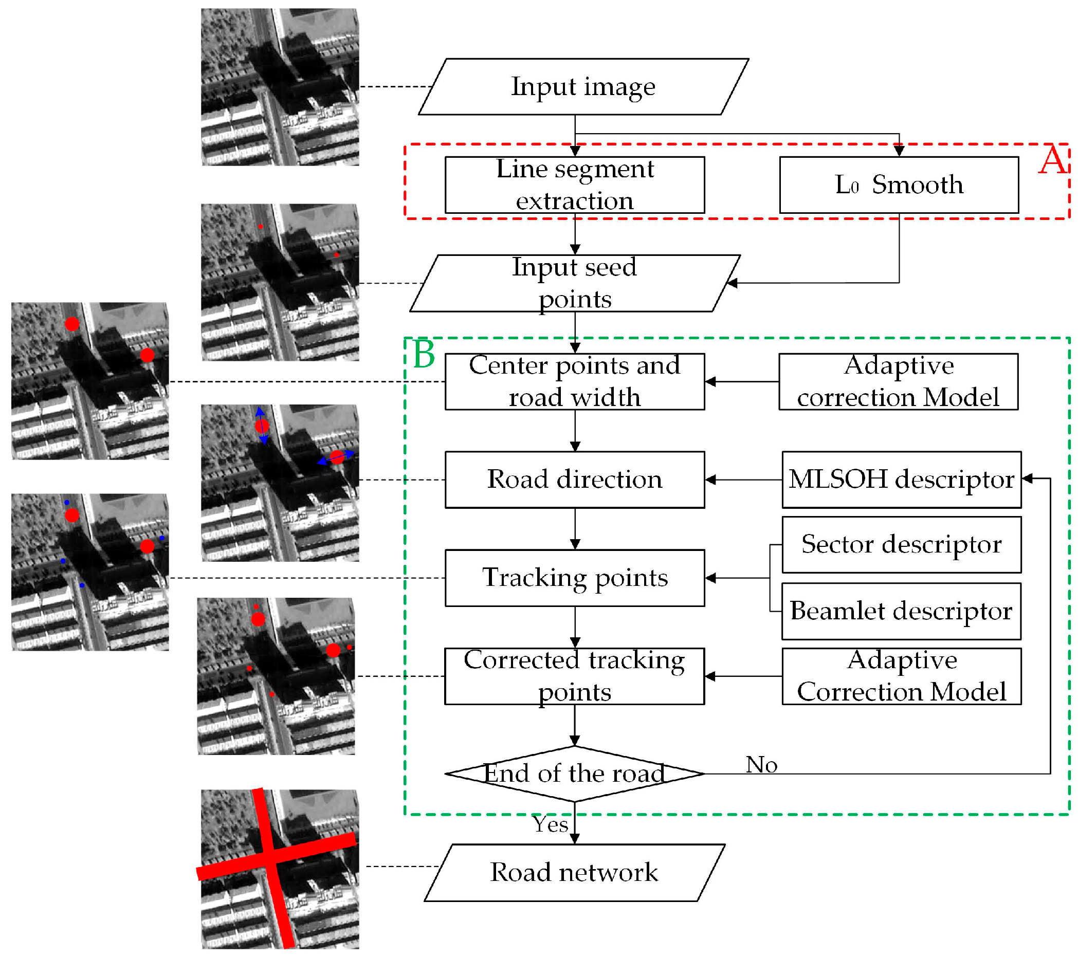
Figure 1. Flow chart.
Remotesensing 11 02672 g001
Figure 2. L0 smoothing result. (a) Input image; (b) result of filtering.
Remotesensing 11 02672 g002
Figure 3. Line extraction result. (a) Input image; (b) result of line extraction.
Remotesensing 11 02672 g003
Figure 4. Matching point correction chart.
Remotesensing 11 02672 g004
Figure 5. Establishment of the rectangular search area.
Remotesensing 11 02672 g005
Figure 6. MLSOH (multi-scale line segment orientation histogram) descriptor.
Remotesensing 11 02672 g006
Figure 7. Sector descriptor.
Remotesensing 11 02672 g007
Figure 8. Beamlet descriptor. (a) Construction of the multiangle beamlet descriptor; (b) gray value change diagram of pixels along the directions of the red, green, and blue lines; (c) the results of shadow-crossing.
Remotesensing 11 02672 g008
Figure 9. Acquisition of tracking points.
Remotesensing 11 02672 g009
Figure 10. Determination of tracking points with clear geometric characteristics: (a) The establishment of search area; (b) the obtention of tracking points.
Remotesensing 11 02672 g010
Figure 11. Gradient threshold analysis.
Remotesensing 11 02672 g011
Figure 12. Peak scaling factor analysis.
Remotesensing 11 02672 g012
Figure 13. First study area: (a) Tracking point result diagram; (b) road extraction result of proposed method; (c) road extraction result of the ERDAS method; (d) road extraction result of the T-shaped template-matching method; (e) road extraction result of the rectangle method; (f) road extraction result of the eCognition method.
Remotesensing 11 02672 g013
Figure 14. Second study area: (a) Tracking point result diagram; (b) road extraction result of proposed method; (c) road extraction result of the ERDAS method; (d) road extraction result of the T-shaped template-matching method; (e) road extraction result of the rectangle method; (f) road extraction result of the eCognition method.
Remotesensing 11 02672 g014
Figure 15. Third study area: (a) Tracking point result diagram; (b) road extraction result of proposed method; (c) road extraction result of the ERDAS method; (d) road extraction result of the T-shaped template-matching method; (e) road extraction result of the rectangle method; (f) road extraction result of the eCognition method.
Remotesensing 11 02672 g015
Table 1. Accuracy evaluation of the first study area.
MethodProposed MethodERDAS MethodeCognition MethodT-shaped MethodRectangle Method
Completeness (%)98.3498.1086.8497.7498.36
Correctness (%)98.6997.4251.8097.8498.54
Quality (%)97.0495.6248.0395.3796.95
Seed Points212370364144
Time (s)10892396203835841741
Table 2. Accuracy evaluation of the second study area.
MethodProposed MethodERDAS MethodeCognition MethodT-shaped MethodRectangle Method
Completeness (%)98.4497.5662.6397.1698.36
Correctness (%)98.9798.6940.8698.5198.48
Quality (%)97.4496.3132.8495.7596.89
Seed Points161710394120
Time (s)8001257147925471039
Table 3. Accuracy evaluation of the second study area.
MethodProposed MethodERDAS MethodeCognition MethodT-shaped MethodRectangle Method
Completeness (%)98.0197.3352.6797.1297.29
Correctness (%)98.4097.3852.8397.6897.87
Quality (%)96.5794.8535.8394.9395.27
Seed Points332770488204
Time (s)16502493253038572236