Abstract
Accurate calibration of oceanic LiDAR signals is essential for the accurate retrieval of ocean optical properties. Nowadays, there are many methods for aerosol LiDAR calibration, but fewer attempts have been made to implement specific calibration methods for oceanic LiDAR. Oceanic LiDAR often has higher vertical resolution, needs greater signal dynamic range, detects several orders of magnitude lower less depth of penetration, and suffers from the effects of the air-sea interface. Therefore the calibration methods for aerosol LiDAR may not be useful for oceanic LiDAR. In this paper, we present a new simple and feasible approach for oceanic LiDAR calibration via comparison of LiDAR backscatter against calculated scatter based on iteratively bio-optical models in clear, open ocean, Type 1 water. Compared with current aerosol LiDAR calibration methods, it particularly considers geometric losses and attenuation occurring in the atmosphere-sea interface. The mean relative error percentage (MREP) of LiDAR calibration constant at two different stations was all within 0.08%. The MREP between LiDAR-retrieved backscatter, chlorophyll after using LiDAR calibration constant with inversion results of measured data were within 0.18% and 1.39%, respectively. These findings indicate that the bio-optical methods for LiDAR calibration in clear ocean water are feasible and effective.
Keywords:
LiDAR calibration; LiDAR constant; bio-optical models; inversion; chlorophyll; backscatter 1. Introduction
Passive ocean color observations have expanded and refined our understanding of global plankton ecosystems, ocean carbon cycle, and the role of the ocean in climate change in the past decades. However, passive measurements are sensitive to only the very near-surface layer, providing no information on vertical structure. Biochemical phenomena and processes often occur at the subsurface of the ocean. For instance, red tides usually occur initially at the subsurface. LiDAR remote sensing has range-resolved capacity, which can provide vertical structure information. And it has energy-concentrated light; thus, it can penetrate inner water dozens of meters deep. Oceanic LiDAR remote sensing of ocean physical, optical, and biogeochemical properties presents an unprecedented new opportunity for overcoming some of the major limitations of passive remote sensing, which have challenged the community for decades [1].
In recent years, shipborne or airborne LiDAR has a wide range of oceanic applications, including bathymetry [2], measuring the optical properties of the water column [3,4,5], also for detecting plankton scattering layers [6,7,8], bubbles [9], internal waves [10], schools of fish [11] and so on. Recent breakthroughs have now demonstrated that plankton properties can be measured with a satellite LiDAR. The satellite LiDAR era in oceanography has arrived [12].
Accurate calibration of LiDAR signals is essential for accurate retrieval, which is related to many parameters involved. The LiDAR calibration constant represents the combined functions of instrument parameters, such as laser energy, optical efficiency of the receiver, and detector electronic gain. Currently, there are mainly four experimental methods that can be used to determine aerosol LiDAR calibration constants: (I) standard diffuse target calibration method in clear, stable, and excellent visibility weather conditions [13]; (II) atmospheric radiative transfer models calibration method, which calculates the aerosol particle spectral distribution through particle counter measurements and calculates the backscattering coefficient, extinction coefficient, and LiDAR ratio through membrane sampling; (III) atmospheric molecular scattering hypothesis calibration method, which assumes that the aerosol scattering contribution is negligible in clear, stable, and excellent visibility weather conditions [14]; and (IV) cross calibration method using the sun radiometer and relatively high power LiDAR for cross calibration [15]. In general, constant micro pulse LiDAR calibration is tedious or difficult.
In the past, there were many methods for aerosol LiDAR calibration, but fewer attempts have been made to implement specific calibration methods for oceanic LiDAR. Oceanic LiDAR often has higher vertical resolution, needs higher signal dynamic range, detects several orders of magnitude lower less depth of penetration, and suffers from the effects of the air–sea interface. The calibration methods for aerosol LiDAR may not be useful for oceanic LiDAR. Current aerosol LiDAR calibration methods have not considered geometric losses and attenuation occurring in the atmosphere-sea interface. In this paper, we present a new simple and feasible approach for oceanic LiDAR calibration via comparing LiDAR backscatter with calculated scatter based on bio-optical models in clear water. First, we compare airborne LiDAR-retrieved attenuation coefficient obtained by using the slope method with the inversion results of water attenuation coefficient on in situ measurements by using bio-optical models. Subsequently, LiDAR calibration constant is iteratively calculated by using bio-optical models. Finally, LiDAR-retrieved backscatter and chlorophyll after using the LiDAR calibration constant are compared with the bio-optical models inversion results based on measured chlorophyll data.
2. Materials and Methods
2.1. Study Area and In Situ Measurements
The experiment took place on 30 September 2017. A total of nine flight tracks were performed in the water near Wuzhizhou Island in Lingshui, SCS. Wuzhizhou Island is located in Haitang Bay in the north of Sanya city, which is far from Monkey Island in the north, and Yalong Bay in the south. It has a coastline of 2.7 km and an area of 1.48 square km. It is shaped like a razor clam, with a length of 1.4 km from east to west and a width of 1.1 km from north to south. During the investigation, the LiDAR was installed on Harbin Y-12 plane, which flew at approximately 307 m above the sea surface. The LiDAR was mounted to point 15° off nadir, and the beginning 18 bins of the LiDAR echoes (above 2-m depth) were removed to reduce unwanted reflection from the surface. Water quality was clear, and bio-optical properties were mostly vertically homogenous, which were suitable for our calibration experiments. The chlorophyll-a concentrations at two calibration stations (see Figure 1) were measured simultaneously, using profile chlorophyll fluorescent probes. PH, temperature, turbidity, and salinity were also measured by a multi-parameter water quality monitor (Manta, Eureka Inc, Detroit, USA) simultaneously during cruises. A total of 26 discrete surface water samples were taken around the Wuzhizhou Island for laboratory chlorophyll measurements. The sampling and measurement principles and methods used here are mainly based on the Ocean Optics Protocols for Satellite Ocean Color Sensor Validation from NASA [16]. Water samples were collected from the surface using a 1.5 L plexiglass hydrophore during the cruises, and then stored in 1 L ambered glass bottles. The samples were then filtered with the polycarbonate filters and the GF/F glass fiber filters for CDOM and particles respectively, and then kept refrigerated for absorption analysis later. Laboratory fluorescence measurements for chlorophyll-a were obtained using a Turner fluorometer (Trilogy, Turner Designs Inc., San Jose, USA). Then, chlorophyll-a concentration was calculated using fluorescence values and the following equation [17], where F is the fluorescence value, v is the dilution volume, V is the actual sample volume and L is the quartz cell’s path length in meters. The estimating chlorophyll using laboratory scanning spectrofluorometer was used to calibrate the in situ profile chlorophyll measurements by profile chlorophyll fluorescent probes via a linear regression (see Figure 2).
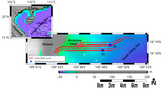
Figure 1.
Study area in Wuzhizhou Island of Hangtang Bay, in the South China Sea. The red lines are airborne LiDAR flight routes taken on 30 September 2017. The blue stars are the shipboard synchronous in situ calibration stations.
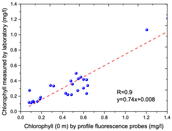
Figure 2.
Line regression between laboratory scanning spectrofluorometer and in situ profile chlorophyll measurements (0 m) by profile chlorophyll fluorescent probes.
2.2. LiDAR System Design
The airborne LiDAR system used here was developed by the Shanghai Institute of Optics and Fine Mechanics (SIOM), Chinese Academy of Sciences (CAS). It employs a frequency-doubled Nd:YAG laser at 532 nm with pulse repetition rate (PRF) of 1 kHz and pulse duration of 1.5 ns. Its pulse energy is 1.5 mJ, and output divergence is 0.25 mrad. The pulse-limited depth resolution is 17.2 cm in water, with a 1.25 Giga-samples per second (GSPS) digitizer; the sample-rate limited depth resolution in water is 8 cm. The telescope diameter is 200 mm, and the field of view (FOV) is 6 mrad. A custom-built trigger generator using a Xilinx (San Jose, California) Kintex-7 field-programmable gate array (FPGA) allows a USB-programmable variable delay to gate the PMTs and trigger the digitizers. Detailed technical parameters of the system can be found in Table 1 in our previous publication [8].
2.3. Calibration Methods
First, mean square error removal, multi-pulse average, and background-noise reduction were applied to improve signal-to-noise ratio (SNR) of the measurements during pretreatment process. Each 50 pulse echoes were averaged, and the signal from ambient noise light was then calculated and subtracted by using the average of the last 100 samples of the pulse. The top of the range for the process was set at a depth of 4 m so that the surface reflection would not affect the results. The bottom of the range was taken to be the depth at which the signal was 0.8 times the water depth, or the depth at which the signal dropped below 5 standard deviations of the background noise.
Under the quasi-small-angle approximation, the oceanic LiDAR equation can be written as [18]:
where is the LiDAR constant to be determined, which is the focus of this paper. It means the multi factor function of instrument parameters, such as laser energy, the optical efficiency of the receiver, and the detector electronic gain, amongst others [12]. One must correct the magnitude of signals for the factors that are unrelated to phytoplankton, such as variation in laser energy, detector electronic gain, and so on. One should particularly consider geometric losses and attenuation occurring in the atmosphere-sea interface for oceanic LiDAR in this study. is the power received from range z. and are the water backscatter and LiDAR attenuation coefficients, respectively. H is the equivalent altitude due to LiDAR tilt angle and water refractive index .
H can be calculated by using LiDAR true flight height and tilt angle [19]:
where is the true altitude of the airborne Lidar, and is Lidar tilt angle. The tilt angle in the water can be expressed by using the Snell’s law: .
The LiDAR equation can be rewritten in the following differential form:
If the water is assumed homogeneous, that is , the LiDAR attenuation coefficient can be expressed directly in terms to signal slope, using the slope method:
where after range correction.
is an “effective” attenuation coefficient, which accounts for the effects of multiple scattering in the water. It closely approximates the beam attenuation coefficient with a narrow FOV and the absorption coefficient with a large FOV [20,21,22]. The multiple scattering effect on can also be expressed as [23]:
Because the FOV of our Lidar system is narrow with 6 mrad, can be assumed as the beam attenuation coefficient in this study. The corresponding profile of attenuation coefficient can be obtained using existing bio-optical models for absorption coefficient and scattering coefficient [24,25,26]:
where C is the concentration of chlorophyll.
The volume scattering function at the Lidar scattering angle of π radians can be calculated as [27,28]:
Using the above equations, the LiDAR constant can be obtained by using the slope method and bio-optical models:
Generally, we can divide the specific calibration process into five steps, as in Figure 3.
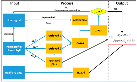
Figure 3.
Flow chart showing the calibration process.
Step I: Match shipborne in situ measurement data with LiDAR signals by temporal–spatial matching. The acquisition time differences of these two kinds of data should not be more than two hours, and we should search the 10 nearest LiDAR signal profiles nearby each shipborne measured station position within 50 m radius.
Step II: Use the slope method to retrieve LiDAR attenuation coefficient.
Step III: Use bio-optical methods to retrieve seawater optical properties, which are needed in Equation (9).
Step IV: Compare LiDAR-retrieved and bio-optical models-retrieved results. If they are similar, input the result into Equation (9); if not, change to the other measurement sites and return to Step I. The mean relative error percentage (MREP) and root mean square error (RMSE) are employed for similarity calculation. The MREP between LiDAR-retrieved and bio-optical models-retrieved results should be within 10%, and RMSE should be within 0.02.
Step V: Continue the iterative operation and finally obtain the mean value of LiDAR constant after mean square error removal.
3. Results and Discussion
3.1. Lidar-Retrieved Attenuation Coefficieent vs. Water Attenuation Coefficieent by Bio-Optical Models
Figure 4 compares airborne LiDAR-retrieved by using the slope method with the inversion results of using the bio-optical models and in situ measurements at Station S1 (109°48.158′E, 18°18.309′N) and Station S2 (109°48.981′E, 18°18.861′N) in the South China Sea. Figure 4a,c is for the data at Station S1, while Figure 4b,d is for the data at Station S2. Each measured curve (red line) corresponds to 10 inversion profiles (black curves) around the station. The profiles of water attenuation coefficient derived from the LiDAR returns and inversion results of shipborne measure data show similar levels of variability over much of the depth range (Figure 4a,b), but their differences increased rapidly when the SNR became small at greater depth. Overall, we see a fairly straight vertical attenuation profile. The Pearson correlation coefficients between LiDAR-retrieved with those by the bio optical models are 0.67 and 0.70, respectively. Figure 4c,d presents the mean relative error percentage (MREP) at S1 and S2 being 7.1% and 9.7%, respectively. The dashed lines indicate the lines of one-to-one correspondence between the LiDAR inversions and the bio-optical inversions. The MREP of LiDAR-retrieved in this study is within 10%. The root mean square error (RMSE) between the two kinds of data at S1 and S2 are 0.012 and 0.018, respectively. The RMSE at the two station are both within 0.02. This suggests that the slope method was feasible and effective for attenuation inversion in homogenous water.
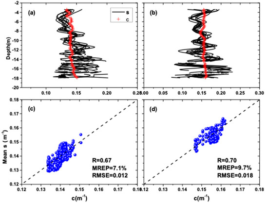
Figure 4.
Comparison of airborne LiDAR-retrieved results with those by bio optical models. (a,c) are for Station S1 (109°48.158′E, 18°18.309′N); (b,d) are for Station S2 (109°48.981′E, 18°18.861′N).
3.2. LiDAR Calibration Constant
Figure 5 shows the LiDAR calibration constant profile calculated by the bio optical models as a function of depth at Station S1 and Station S2. To minimize the reflection effects from the surface, the first 40 bins of the LiDAR echoes (above 4.5-m depth) were removed. The bottom of the range was taken to be the depth at which the signal was 0.8 times the water depth. Figure 5a,b shows fairly straight vertical profiles, which means the function of instrument parameters, such as laser energy, optical efficiency of the receiver, and the detector electronic gain. The max relative error percentage at both stations is within 8.3%, and their MREP is within 0.08%. The mean Lidar constant is for our Lidar system. The RMSE of lidar constant at S1 and S2 are and , respectively. The mean standard deviation are and , respectively. The small MREP and nearly straight vertical profile indicated our bio optical models for Lidar calibration constant was robust.
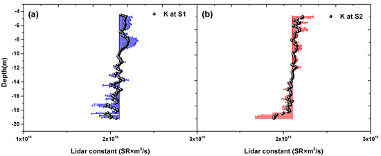
Figure 5.
LiDAR constant calculated by bio optical models as a function of depth (a,b). The colored error bars denote standard deviation.
3.3. Validation
To validate the accuracy of LiDAR calibration constant, we compared the LiDAR retrieved backscatter, chlorophyll after using the obtained LiDAR calibration constant with the bio-optical model inversion results and in situ measurements. Figure 6a,b compares airborne LiDAR-retrieved and the results from the bio-optical model and in situ measurements at Stations S1 and S2, respectively. The profiles of derived from the LiDAR returns show fairly similar levels of variability over much of the depth range compared with the bio-optical model inversion results of in situ measurements, but their differences increased slightly when the SNR became smaller at greater depths (Figure 6a,b). Overall, there is a good agreement between the two. The Pearson correlation coefficients between LiDAR-retrieved and those by the bio optical model are 0.52 and 0.58 at the two stations, respectively. The MREP values at S1 and S2 are 0.18% and 0.08%, respectively. The mean retrieved by bio optical model and lidar method at S1 are and , the mean value difference between the two is . Similarly, the mean values by the two methods at S2 are and , the mean value difference between the two is . The RMSE between the Lidar-retrieved and those by the bio optical model at S1 and S2 are and , respectively. The RMSE at the two station are both within . Figure 6c,d compares airborne LiDAR-retrieved chlorophyll and inversion results by the bio-optical model and in situ measurements at the two stations, respectively. They also show good agreement. The Pearson correlation coefficients between LiDAR-retrieved and those by the bio optical model at S1 and S2 are 0.46 and 0.54, respectively. The MREP values at S1 and S2 are 1.39% and 1.15%, respectively. The mean retrieved chlorophyll by bio optical model and LiDAR method at S1 are 0.144 and 0.141, the mean value difference between the two is 0.003. Similarly, the mean values by the two methods at S2 are 0.119 and 0.113, the mean value difference between the two is 0.006. The RMSE between the LiDAR-retrieved chlorophyll and those by the bio optical model at S1 and S2 are 0.0103 and 0.0102, respectively. The RMSE at the two station are both within 0.015. These results indicate that the bio-optical method for LiDAR calibration used in this study is feasible and effective.
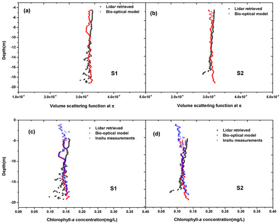
Figure 6.
Comparison of airborne Lidar-retrieved and chlorophyll after using the Lidar calibration constant with the bio-optical model inversion results of in-situ measurements. (a,c) are for Station S1; (b,d) are for Station S2.
4. Discussion
Current LiDAR calibration methods are mostly for atmosphere LiDAR, and do not consider geometric losses and attenuation occurring in the atmosphere-sea interface. Our method for LiDAR calibration constant is based on comparing measured Lidar backscatter with calculated backscatter by bio-optical models in clear water. It is simple and feasible, and includes the effect of the atmosphere-sea interface. Compared to common standard diffuse target calibration method, we save the cost for buying diffuse reflection plate and the experimental procedure is simpler. The signal profiles in Figure 5a,b both appear fairly straight, revealing that they are only affected by the instrument parameters, not by the water changes. This reflects that the effects of water changes were effectively removed using our calibration method from another perspective. Therefore, we could obtain the LiDAR constant from the mean value of this vertical profile. The blue and red error bars (donate standard deviation) of LiDAR constant in Figure 5a,b are both small, which reveals the effectiveness of our method. Comparison of airborne LiDAR-retrieved after using the LiDAR calibration constant with the bio-optical model inversion results of in situ measurements further proves the accuracy of the method (Figure 6).
It seems that the mean K value plotted in Figure 5a,b have errors which are nearly uniformly high above the depths of 10–12 m in the two stations, and nearly uniformly low in the depths greater than the 10–12 m depths. The systematic error may be very likely due to the inadequacy of fluorescence measurements to accurately estimate chlorophyll concentration. This systematic error in the K constant determination will give problems in applying this method and the K constants determined from it to other parts of the ocean. There seems to be a peculiar pattern in the inverted values of volume scattering at the LiDAR scattering angle of π radians and the concentration of chlorophyll for Station 1. in the depths where SNR is not too high the LiDAR, inversion varies in an opposite fashion to the bio-optical inversion. For both parameters the LiDAR inversion reads high when the bio-optical inversion reads low and vice-versa. This could relate to the K constant systematic error. The implementation that chlorophyll concentration determined by HPLC would eliminate this problem. HPLC method may be time-consumed for profile sampling and measurements. One method is to measure several different depths (for instance, 1 m, 5 m, 7 m etc.) use HPLC method, then the measured discrete data are employed to calibrate the in situ profile chlorophyll measurements. Considering the in situ profile chlorophyll fluorescent probes possible precision problem, we have used laboratory scanning spectrofluorometer to calibrate the in situ profile chlorophyll measurements via a linear regression, see Figure 2.
In order to remove the water-change effects on the LiDAR signal calibration process, it is better to choose clear and nearly vertical homogenous Type 1 water for LiDAR calibration. Larger concentrations of chlorophyll do not correlate well with scattering and backscattering, nor the uncertainty in the cell size. To a lesser extent, uncertainties in the C-to-volume ratio accounted for the larger part of the uncertainty in Cf (sum of the contributions from each phytoplankton type) [29]. The bio-optical model described in this paper (Equations (5)–(8)) may not work well in this condition. Due to the LiDAR calibration constant is only dependent on LiDAR system parameters and independent of water types, we could then use the estimated Lidar calibration constant from Type 1 clear water for Type 2 complex water inversion to obtain the vertical structure. A common LiDAR inversion method is slope method, which is based on the assumption of homogenous water. Unfortunately, assumptions like this appear not to be well justified for many situations of interest, e.g., under conditions of subsurface phytoplankton layer. Even under the relatively stable conditions, significant local heterogeneities occur. There are improved methods, such as Fernald [30] and Klett [31], which have been widely used in inhomogeneous mediums. However, these methods depend on accurate acquisition of LiDAR ratio, which will make the calibration algorithm a lot more complex. The technique used in this work assumed that the water was optically homogenous and attenuation was slowly varying with depth. Based on this assumption, we could use the slope method and bio-optical model to obtain the two quantities in the LiDAR equation, namely, attenuation and backscatter coefficients. We have chosen clear and nearly vertical homogenous water for experiments, and measured 26 stations. Our in situ measurements for attenuation coefficient at the two calibration stations present a fairly constant profile (see Figure 4), and so we can assume that the water is vertical homogenous and simply use the slope method.
5. Conclusions
In this study, we developed a new simple and feasible approach for oceanic LiDAR calibration via comparison of LiDAR backscatter from calculated scatter based on the bio-optical model in clear, open ocean, Type 1 water. Compared with current aerosol LiDAR calibration methods, it particularly considers geometric losses and attenuation occurring in the atmosphere-sea interface. Our results indicate that the method is feasible and effective. The technique used in this work assumed that the water was optically homogenous and attenuation was slowly varying with depth. Based on this assumption, we could use the slope method and bio-optical model to obtain the two quantities in the LiDAR equation; Namely attenuation and backscatter coefficients. The LiDAR calibration constant was thus obtained. Considering the difference of regional biologic optical models, further investigation is needed to confirm airborne LiDAR experiments in various sea areas to enhance and validate this new method. Comparison with other calibration methods should also be carried out.
Author Contributions
Funding acquisition, Z.M.; Methodology, P.C.; Supervision, D.P.; Visualization, H.L.
Funding
This research was funded by the National Key Research and Development Program of China grant number 2016YFC1400902; the Scientific Research Fund of the Second Institute of Oceanography, State Oceanic Administration grant number QNYC1803; and the Zhejiang Natural Science Foundation grant number LQ19D060003. And the APC was funded by the National Key Research and Development Program of China grant number 2016YFC1400902.
Acknowledgments
We thank our colleagues at the SIO for taking in situ measurements. We thank anonymous reviewers for their suggestions that significantly improved the presentation of the paper, and Zuojun Yu for editing the paper.
Conflicts of Interest
The authors declare no conflicts of interest.
References
- Behrenfeld, M.J.; Hu, Y.; O’Malley, R.T.; Boss, E.S.; Hostetler, C.A.; Siegel, D.A.; Sarmiento, J.L.; Schulien, J.; Hair, J.W.; Lu, X. Annual boom-bust cycles of polar phytoplankton biomass revealed by space-based lidar. Nat. Geosci. 2016, 10, 118–122. [Google Scholar] [CrossRef]
- Irish, J.L.; Mcclung, J.K.; Llllycrop, W.J. Airborne lidar bathymetry: The SHOALS system. Bull. Int. Navig. Assoc. 2000, 103, 43–53. [Google Scholar]
- Churnside, J.H.; Marchbanks, R.D.; Lembke, C.; Beckler, J. Optical backscattering measured by airborne lidar and underwater glider. Remote Sens. 2017, 9, 379. [Google Scholar] [CrossRef]
- Lee, J.H.; Churnside, J.H.; Marchbanks, R.D.; Donaghay, P.L.; Sullivan, J.M. Oceanographic lidar profiles compared with estimates from in situ optical measurements. Appl. Opt. 2013, 52, 786–794. [Google Scholar] [CrossRef] [PubMed]
- Kokhanenko, G.P.; Balin, Y.S.; Penner, I.E.; Shamanaev, V.S. Lidar and in situ measurements of the optical parameters of water surface layers in Lake Baikal. Atmos. Ocean. Opt. 2011, 24, 478–486. [Google Scholar] [CrossRef]
- Churnside, J.H.; Marchbanks, R.D. Subsurface plankton layers in the Arctic Ocean. Geophys. Res. Lett. 2015, 42, 4896–4902. [Google Scholar] [CrossRef]
- Churnside, J.H.; Donaghay, P.L. Thin scattering layers observed by airborne lidar. ICES J. Mar. Sci. 2009, 66, 778–789. [Google Scholar] [CrossRef]
- Liu, H.; Chen, P.; Mao, Z.; Pan, D.; He, Y. Subsurface plankton layers observed from airborne lidar in Sanya Bay, South China Sea. Opt. Express 2018, 26, 29134–29147. [Google Scholar] [CrossRef]
- Churnside, J. Lidar signature from bubbles in the sea. Opt. Express 2010, 18, 8294–8299. [Google Scholar] [CrossRef]
- Churnside, J.H.; Marchbanks, R.D.; Lee, J.H.; Shaw, J.A.; Weidemann, A.; Donaghay, P.L. Airborne lidar detection and characterization of internal waves in a shallow Fjord. J. Appl. Remote Sens. 2012, 6, 3611. [Google Scholar] [CrossRef]
- Roddewig, M.R.; Pust, N.J.; Churnside, J.H.; Shaw, J.A. Dual-polarization airborne lidar for freshwater fisheries management and research. Opt. Eng. 2017, 56, 031221. [Google Scholar] [CrossRef]
- Hostetler, C.A.; Behrenfeld, M.J.; Hu, Y.; Hair, J.W.; Schulien, J.A. Spaceborne Lidar in the Study of Marine Systems. Annu. Rev. Mar. Sci. 2018, 10, 121–147. [Google Scholar] [CrossRef] [PubMed]
- O’Connor, E.J.; Illingworth, A.J.; Hogan, R.J.; Technology, O. A technique for autocalibration of cloud lidar. J. Atmos. Ocean. Technol. 2004, 21, 777–786. [Google Scholar] [CrossRef]
- Powell, K.A.; Hostetler, C.A.; Liu, Z.; Vaughan, M.A.; Kuehn, R.E.; Hunt, W.H.; Lee, K.P.; Trepte, C.R.; Rogers, R.R.; Young, S.A. CALIPSO Lidar Calibration Algorithms. Part I: Nighttime 532-nm Parallel Channel and 532-nm Perpendicular Channel. J. Atmos. Ocean. Technol. 2009, 26, 2015–2033. [Google Scholar] [CrossRef]
- Biele, J.; Beyerle, G.; Baumgarten, G. Polarization lidar: Corrections of instrumental effects. Opt. Express 2000, 7, 427–435. [Google Scholar] [CrossRef]
- Mitchell, B.G.; Kahru, M.; Wieland, J.; Stramska, M. Determination of spectral absorption coefficients of particles, dissolved material and phytoplankton for discrete water samples. Ocean Opt. Protoc. Satell. Ocean Color Sens. Validation Revis. 2002, 3, 231–257. [Google Scholar]
- Welschmeyer, N.A. Fluorometric analysis of chlorophyll a in the presence of chlorophyll b and pheopigments. Limnol. Oceanogr. 1994, 39, 1985–1992. [Google Scholar] [CrossRef]
- Bissonnette, L.R. Sensitivity analysis of lidar inversion algorithms. Appl. Opt. 1986, 25, 2122–2125. [Google Scholar] [CrossRef] [PubMed]
- Kopilevich, Y.I.; Surkov, A.G. Mathematical modeling of the input signals of oceanological lidars. J. Opt. Technol. 2008, 75, 321–326. [Google Scholar] [CrossRef]
- Gordon, H.R. Interpretation of airborne oceanic lidar: Effects of multiple scattering. Appl. Opt. 1982, 21, 2996–3001. [Google Scholar] [CrossRef]
- Walker, R.E.; McLean, J.W. Lidar equations for turbid media with pulse stretching. Appl. Opt. 1999, 38, 2384–2397. [Google Scholar] [CrossRef] [PubMed]
- Chen, P.; Pan, D.; Mao, Z.; Liu, H. Semi-analytic Monte Carlo radiative transfer model of laser propagation in inhomogeneous sea water within subsurface plankton layer. Opt. Laser Technol. 2019, 111, 1–5. [Google Scholar] [CrossRef]
- Churnside, J.H. Review of profiling oceanographic lidar. Opt. Eng. 2014, 53, 051405. [Google Scholar] [CrossRef]
- Morel, A.; Maritorena, S. Bio-optical properties of oceanic waters: A reappraisal. J. Geophys. Res. Ocean. 2001, 106, 7163–7180. [Google Scholar] [CrossRef]
- Gordon, H.R.; Morel, A.Y. Remote Assessment of Ocean Color for Interpretation of Satellite Visible Imagery: A Review; Springer Science & Business Media: Berlin/Heidelberg, Germany, 2012; Volume 4. [Google Scholar]
- Prieur, L.; Sathyendranath, S.J.L. An optical classification of coastal and oceanic waters based on the specific spectral absorption curves of phytoplankton pigments, dissolved organic matter, and other particulate materials 1. Limnol. Oceanogr. 1981, 26, 671–689. [Google Scholar] [CrossRef]
- Churnside, J.H.; Sullivan, J.M.; Twardowski, M.S. Lidar extinction-to-backscatter ratio of the ocean. Opt. Express 2014, 22, 18698–18706. [Google Scholar] [CrossRef] [PubMed]
- Churnside, J.H.; Marchbanks, R.D. Inversion of oceanographic profiling lidars by a perturbation to a linear regression. Appl. Opt. 2017, 56, 5228–5233. [Google Scholar] [CrossRef] [PubMed]
- Martinez-Vicente, V.; Dall’Olmo, G.D.; Tarran, G.; Boss, E.; Sathyendranath, S. Optical backscattering is correlated with phytoplankton carbon across the Atlantic Ocean. Geophys. Res. Lett. 2013, 40, 1154–1158. [Google Scholar] [CrossRef]
- Fernald, F.G. Analysis of atmospheric lidar observations: Some comments. Appl. Opt. 1984, 23, 652. [Google Scholar] [CrossRef]
- Klett, J.D. Stable analytical inversion solution for processing lidar returns. Appl. Opt. 1981, 20, 211–220. [Google Scholar] [CrossRef]
© 2019 by the authors. Licensee MDPI, Basel, Switzerland. This article is an open access article distributed under the terms and conditions of the Creative Commons Attribution (CC BY) license (http://creativecommons.org/licenses/by/4.0/).