Article

Multi-Temporal DInSAR to Characterise Landslide Ground Deformations in a Tropical Urban Environment: Focus on Bukavu (DR Congo)

by
Adriano Nobile
1,*,
Antoine Dille
1,2,
Elise Monsieurs
1,3,4,
Joseph Basimike
5,
Toussaint Mugaruka Bibentyo
5,
Nicolas D’Oreye
6,7,
François Kervyn
1 and
Olivier Dewitte
1
1
Department of Earth Sciences, Royal Museum for Central Africa, Leuvensesteenweg 13, 3080 Tervuren, Belgium
2
Department of Geography, Earth System Science, Vrije Universiteit Brussel, Pleinlaan 2, 1050 Brussels, Belgium
3
Department of Geography, University of Liège, clos Mercator, 3, 4000 Liège, Belgium
4
F. R. S.—FNRS, Rue d’Egmont, 5, 1000 Brussels, Belgium
5
Department of Geology, Université Officielle de Bukavu, Site Universitaire de Karhale, Kadutu, 570 Bukavu, DR Congo
6
European Center for Geodynamics and Seismology, Rue Josy Welter, 19, L-7256 Walferdange, Luxembourg
7
Department of Geophysics/Astrophysics, National Museum of Natural History, Rue Münster, 25, L-2160 Luxembourg City, Luxembourg
*
Author to whom correspondence should be addressed.
Remote Sens. 2018, 10(4), 626; https://doi.org/10.3390/rs10040626
Submission received: 14 March 2018 / Revised: 5 April 2018 / Accepted: 9 April 2018 / Published: 18 April 2018
(This article belongs to the Special Issue Radar Interferometry for Geohazards)

Abstract

:
Landslides can lead to high impacts in less developed countries, particularly in tropical environments where a combination of intense rainfall, active tectonics, steep topography, and high population density can be found. However, the processes controlling landslide initiation and their evolution through time remains poorly understood. Here we show the relevance of the use of the multi-temporal differential radar interferometric (DInSAR) technique to characterise ground deformations associated with landslides in the rapidly-expanding city of Bukavu (DR Congo). We use 70 COSMO-SkyMed synthetic aperture radar images acquired between March 2015 and April 2016 with a mean revisiting time of eight days to produce ground deformation rate maps and displacement time series using the small baseline subset approach. We find that various landslide processes of different ages, mechanisms, and states of activity can be identified. Ground deformations revealed by DInSAR are found consistent with field observations and differential GPS measurements. Our analysis highlights the ability of DInSAR to grasp landslide deformation patterns affecting the complex tropical-urban environment of the city of Bukavu. However, longer time series will be needed to infer landside responses to climate, seismic, and anthropogenic drivers.

Graphical Abstract

1. Introduction

Landslides represent significant hazards in dissected landscapes, where they can result in fatalities and damage to infrastructure and the natural environment. Landslides can lead to high impacts in less developed countries, particularly in tropical environments, where a combination of intense rainfall, active tectonics, highly-weathered lithology, and high population density can be found [1,2,3,4,5]. Landslide frequency in these regions is expected to increase in the future in response to increasing demographic pressure, deforestation and climate change [6,7,8]. In addition, the processes controlling the timing of landslide initiation and their evolution through time remain poorly understood [1,9].
Kinematics is a key knowledge for understanding landslide processes. Such knowledge can bring information on, e.g., temporally- and spatially-variable stresses acting within landslides, their boundary geometries, external forcing conditions, and characteristics of future landslide movement [10]. Characterization of such deformations benefits greatly from the combination of modern monitoring techniques with increased spatiotemporal resolution and adapted to the deformation dynamics, the scale of deforming area and the environmental context. Ideally, a combination of satellite remote sensing, ground-based monitoring techniques, and field observations offers the best options (e.g., [10,11,12,13]).
In the tropics, the frequent cloud cover limits the use of optical satellites imagery [14]. In such a context, the all-weather, day and night acquisition capabilities of radar are an asset. In particular, the use of multi-temporal differential synthetic aperture radar interferometry (DInSAR) techniques such as permanent scatter interferometry (PSI [15,16]) or small baseline subset (SBAS [17,18]) offers millimetre accuracy, high temporal and areal density of measurements that are especially suited for the detection and monitoring of slow ground surface deformations [19,20,21,22,23,24]. These multi-temporal techniques, moreover, limit the effect of atmospheric artefacts [20,25] that are potentially important over these tropical areas [26,27]. In recent years, many authors have applied these techniques using products from second-generation X-band SAR sensors, such as the German TerraSAR-X and the Italian COSMO-SkyMed (CSK) constellation, taking advantage of the improved spatial and temporal resolution to make accurate measures of surface deformation (e.g., [28,29,30,31,32,33]). The characteristics of these sensors make them particularly suited for detailed and fine-scale study of landslides in urbanised environments [28,30,34,35]. Indeed, in those areas, the abundance of anthropic structures with stable backscattering properties increases the density of measurable coherent target (i.e., persistent scatters [28,32]).
In the present study, we show the relevance of multi-temporal DInSAR techniques to characterise the kinematics of landslides in a complex and data-scarce tropical-urban environment. The region of interest lies in the city of Bukavu (DR Congo), a rapidly expanding urban area set in a landslide-prone environment [36,37]. We follow a two-step validation procedure involving geomorphological mapping and differential GPS (DGPS) measurements to assess the capability of DInSAR to detect and characterise the ground deformations affecting the city.

2. Study Area

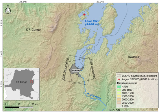
The city of Bukavu is located in the Democratic Republic of Congo, on the southern shore of Lake Kivu in the western branch of the East African Rift (Figure 1). Bukavu counts currently ~800.000 inhabitants and is characterised by a rapid uncontrolled expansion [38]. A large part of the city is affected by landslides [36,37]. These continuous ground movements are responsible for recurring degradation and destruction of houses, buildings, and roads, but also of water networks and sewerage infrastructures [36]. The processes affect particularly new inhabitants living in poor conditions. These newcomers are often forced to relocate from rural areas to the city due to the conflicts affecting the region for years. They have no choice but to settle in steep and unstable areas, where they also contribute to landslides by altering, e.g., the water drainage [39].
The N–S elongated rift offers general E–W slope orientations. Such a geometry is ideally suited to the use of space-borne DInSAR techniques that are more sensitive to deformations in E–W and vertical directions rather than N–S because of the sub-polar orbits of the SAR satellites (e.g., [40]). Furthermore, the active tectonic of the rift is responsible for the frequent occurrence of earthquakes [41,42] that, in combination with the intense rainfall are, in part, responsible for the triggering and reactivation of landslides in the region [3].

3. Materials and Methods

3.1. SAR Data and DInSAR Processing

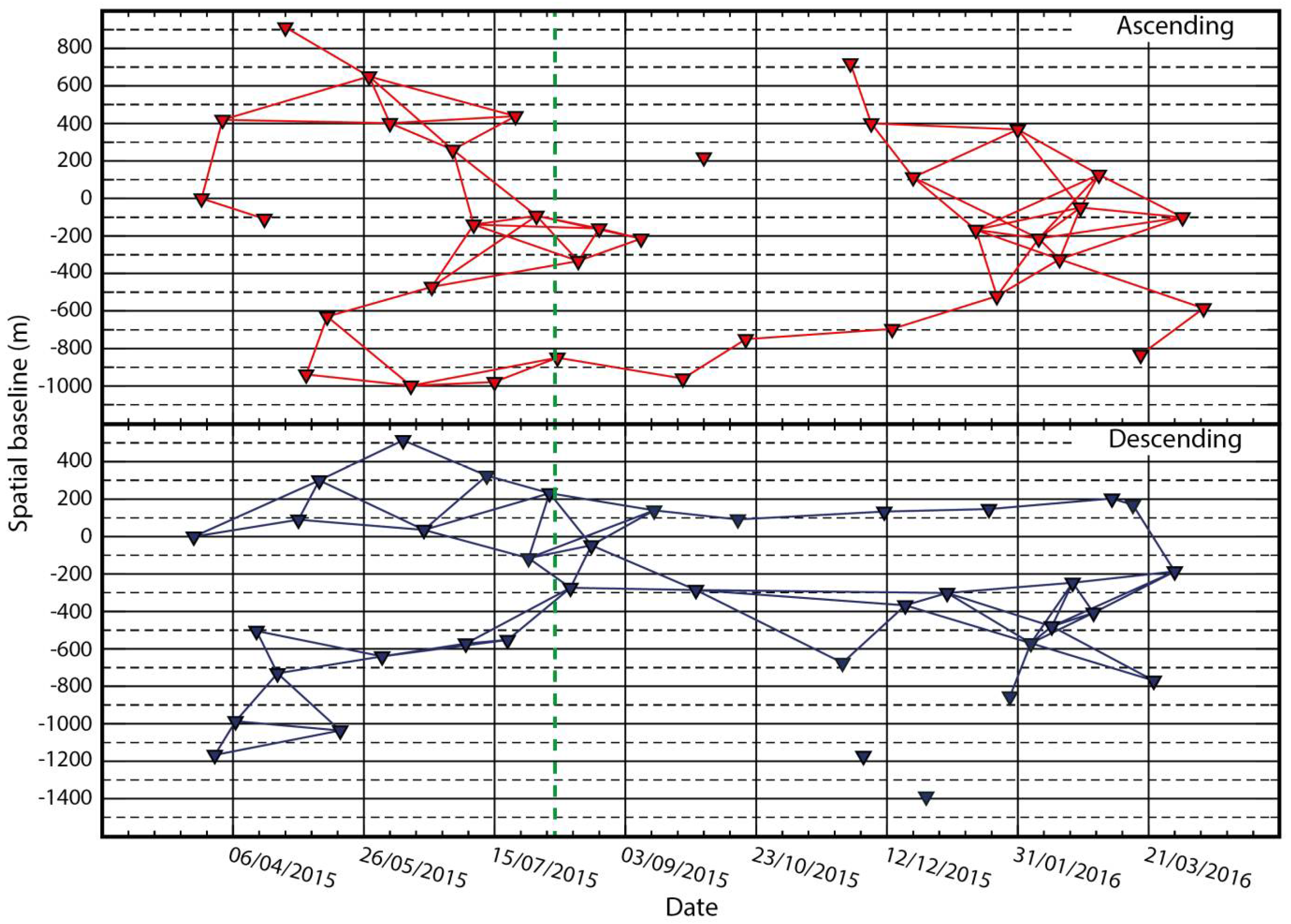
A set of 70 single look complex (SLC) CSK images (35 in each ascending and descending pass) are used in this study. This dataset spans from March 2015 to April 2016 with a mean revisiting time of eight days (per orbit). There is, however, a temporal gap of about 40 days between October and November 2015 (Figure 2). The COSMO-SkyMed constellation is composed of four satellites equipped with an X-band radar sensor (3.12 cm wavelength). We used StripMap HIMAGE data with a scene size of 40 × 40 km and a spatial resolution of ~3 × 3 m in azimuth and range. Since this study focuses on landslides in the urban environment of Bukavu, we processed only a ~15 × 15 km subset of the entire CSK image footprint that covers the city and its close surroundings (Figure 1).
Deformation rate maps and displacement time series are produced by processing two sets of interferograms (62 in ascending and 61 in descending—Figure 2) with StaMPS software (School of Earth and Environment, University of Leeds, Leeds LS2 9JT, UK) [43] using the SBAS technique [17,18]. The use of a multitude of pair combinations in this method allows taking advantage of the high temporal sampling offered by CSK constellation to maintain a greater number of coherent pixels as well as the reduction of the effect of atmospheric errors (e.g., [18,44,45,46]) with respect to the PSI approach where a single master is used [15,47].
Interferograms are obtained from the processing of the SAR image dataset using Doris software (TU-Delft release) (Delft Institute of Earth Observation and Space Systems (DEOS), Faculty of Aerospace Engineering Delft University of Technology, Kluyverweg, 1, 2629 HS Delft, The Netherlands). These interferograms were selected for their short temporal (<64 days) and spatial (<400 m) baselines (Figure 2) to limit coherence loss between pixels [46]. To avoid gaps in the chain of interferograms that could produce artefacts [48], we added two interferograms with larger temporal parameters (80 and 96 days respectively) in the descending dataset. In order to remove the topographic phase component, we used the SRTM 1-arcsec digital elevation model (DEM) [49]. The interferograms were filtered [50] and multi-looked to obtain pixels of ~10 × 10 m. The unwrapping was performed using the 3D (in space and time) algorithm available in StaMPS [51]. Since multi-temporal DInSAR technique measures the relative displacement with respect to a fixed point, we use one of the permanent GNSS stations of the Kivu-G-Net network [52] as reference. The BUK station is situated close to the city centre, 2 km away from the main landslide area. It was occupied by a temporary GPS receiver during the present study (from 2015 to 2016) and has been transformed into a permanent station since December 2016. That reference point, measured with an independent high-resolution GNSS method, can be considered as a stable reference point for the DInSAR processing.
A significant part of the errors on displacement measurements obtained for a single interferogram is related to the phase noise registered by the radar [53,54]. The main source of noise is caused by the radar signal propagation through a variable atmosphere; temperature, pressure and in particular variations of water vapour content in the atmosphere produce delays that can lead to measurement errors up to several centimetres [26,27,54]. In tropical environments, those are expected to be significant due to the considerable variability of the atmospheric properties across the year [55,56]. Other sources of errors with DInSAR measurements include residuals from topographic and orbital phase components that were not correctly estimated during the DInSAR processing, as well as misinterpretations of the phase difference during the unwrapping process (e.g., [44]). The latter can produce a 2nπ phase jump that lead to an error that can be n times half a wavelength (n being an integer). Specific algorithms included in StaMPS, allow to partially correct orbital, topographic, unwrapping and, in a limited way, atmospheric errors [26,43,51].
Since standard multi-temporal interferometric software do not generally provide estimates of the measurement accuracy (e.g., [57]), the latter is frequently evaluated by comparing the DInSAR deformation time series with the one obtained from permanent GNSS stations in the area (e.g., [18,58]) or by performing statistical analysis of the signal to estimate the phase noise component (e.g., [57,59]). Generally, the accuracy of DInSAR measurements varies from 1 to 5 mm/year (e.g., [18,26,59]); a value that depends strongly on the sensor wavelength, the number of acquisitions and interferograms processed and other parameters such as the general coherence over the area. Since no permanent GNSS station was acquiring in the study area during the entire investigated period, we estimate the accuracy of the DInSAR measurements by analysing the noise present in the deformation signal recorded. The residual phase noise was evaluated by computing the standard deviation of the signal within a 1 km2 subset of the deformation map that is showing a low signal to noise ratio. This area surrounds the location of the BUK station that can be considered as stable. That standard deviation is used as a proxy for the accuracy of the displacement rate measurement.

3.2. Geomorphological Landslide Inventory

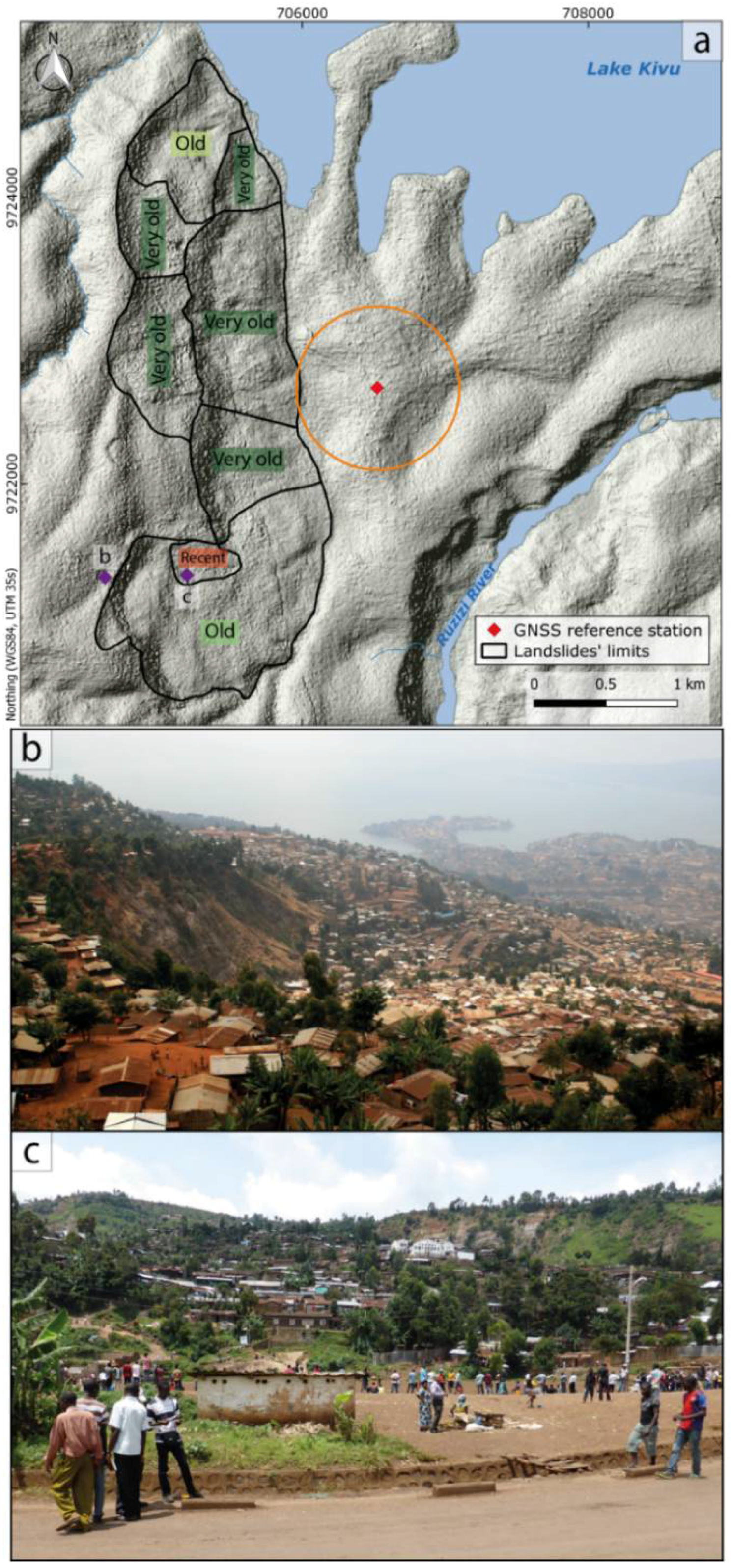
In order to validate the captured DInSAR deformations, we assembled a landslide inventory for a large hillslope oriented towards the east and known for currently being affected by ground instability (Figure 3). The inventory is built from combining intense field survey with visual interpretation of historical aerial photos from 1959 and very high-resolution Pléiades images from 2013. The hillslope is affected by landslides in various and contrasting land use and land cover contexts (very dense habitat, large roads, moderate vegetation, bare soils, and forests). The largest landslides show morphological characteristics of large deep-seated rotational slides (classification based on [60]). They predate clearly the first city settlements. Some are quite eroded and look pretty old and stable (classified here as very old) whilst others seem more recent and have parts that show current deformation activity (classified as old). Among those landslides stands the largest one (1.5 km²) in a slum neighbourhood named Funu. This landslide is known for being very active and having some parts continuously moving. Rotational over its trigger area, this slide shows flow-like features in its runout and accumulation zones. This slide is densely populated, with ~80.000 people (most of them very poor) living on it [38].

3.3. DGPS Measurements

DGPS measurements were carried out in static acquisition mode with Leica GX1230 (Leica Geosystems AG, Heinrich-Wild-Strasse 9435 Heerbrugg, Switzerland) dual-frequency receivers at six benchmarks; five being spread across this large 1.5 km² landslide, one outside in a stable area. Measurements were taken between January 2015 and October 2016. Benchmarks are solid concrete structures that were already in place, such as a water fountain or street curb. In the particular social context of the study area, these structures are more certain to remain in place compared to new structures (e.g., survey point nails) that could easily be damaged or removed by local inhabitants. The reference point is the same as the one used for the calibration of the DInSAR-derived displacements. The receiver at the roving points was left in place for five minutes with a data acquisition set at every second. Measurement duration at roving sites is constrained by the safety of operators and equipment in this very densely populated and poor area, although we acknowledge that position accuracy would increase from longer sessions [61]. To anticipate the tropospheric delay near the equator, a maximum geometric dilution of precision has been set to five during measurements [62]. Data were processed with Leica Geosystems post-processing software in order to calculate the relative position changes of the benchmarks. Post-processing integrated precise ephemeris data for each DGPS campaign, respectively. With a maximum baseline of 2.4 km, all ambiguities have been solved. The accuracy achieved for the DGPS locations was evaluated to 7.5 mm for the horizontal component and 16.5 mm for the vertical component. These uncertainties refer to the internal precision of the measurement, field conditions, and data post-processing. We assumed that all benchmarks and the reference station move at the same rift opening rate (~2 mm/year [42]).
To ensure a consistent comparison of the DGPS and DInSAR displacements, we projected the three dimensional DGPS displacement vectors into the radar ascending and descending looking geometries (Figure S1). Since the DGPS data were acquired with a longer revisiting period but for a longer time span (5–9 acquisitions in 22 months) with respect to the DInSAR data (35 acquisitions per orbit in 13 months), we compared the DGPS deformation rate estimated over the whole period of 22 months (evaluated through a linear regression) instead from the use of shorter displacement time series that are less stable (Figure S1). Given the vertical and horizontal DGPS accuracy (16.5 and 7.5 mm, respectively) and the satellite looking angle in ascending and descending orbits (42 and 49 degrees, respectively), the accuracy of individual DGPS measures in the LOS direction is 14 mm in ascending and 12 mm in descending geometry. The error on the rates at the individual benchmarks varies from 4 to 8 mm/year, depending on the number of acquisitions.
To estimate the reliability of the use of the DGPS rate instead of the time series, we evaluate the linear correlation coefficient for the measurements at single benchmarks. This coefficient is greater than 0.9 for all the DGPS benchmarks except for benchmark A (0.5 for ascending and 0.4 for descending LOS) and benchmark C in descending (0.6; Figure S1). These points, however, show displacements smaller than the measurement error over the entire period of acquisition.

4. Results

4.1. DInSAR Ground Deformations

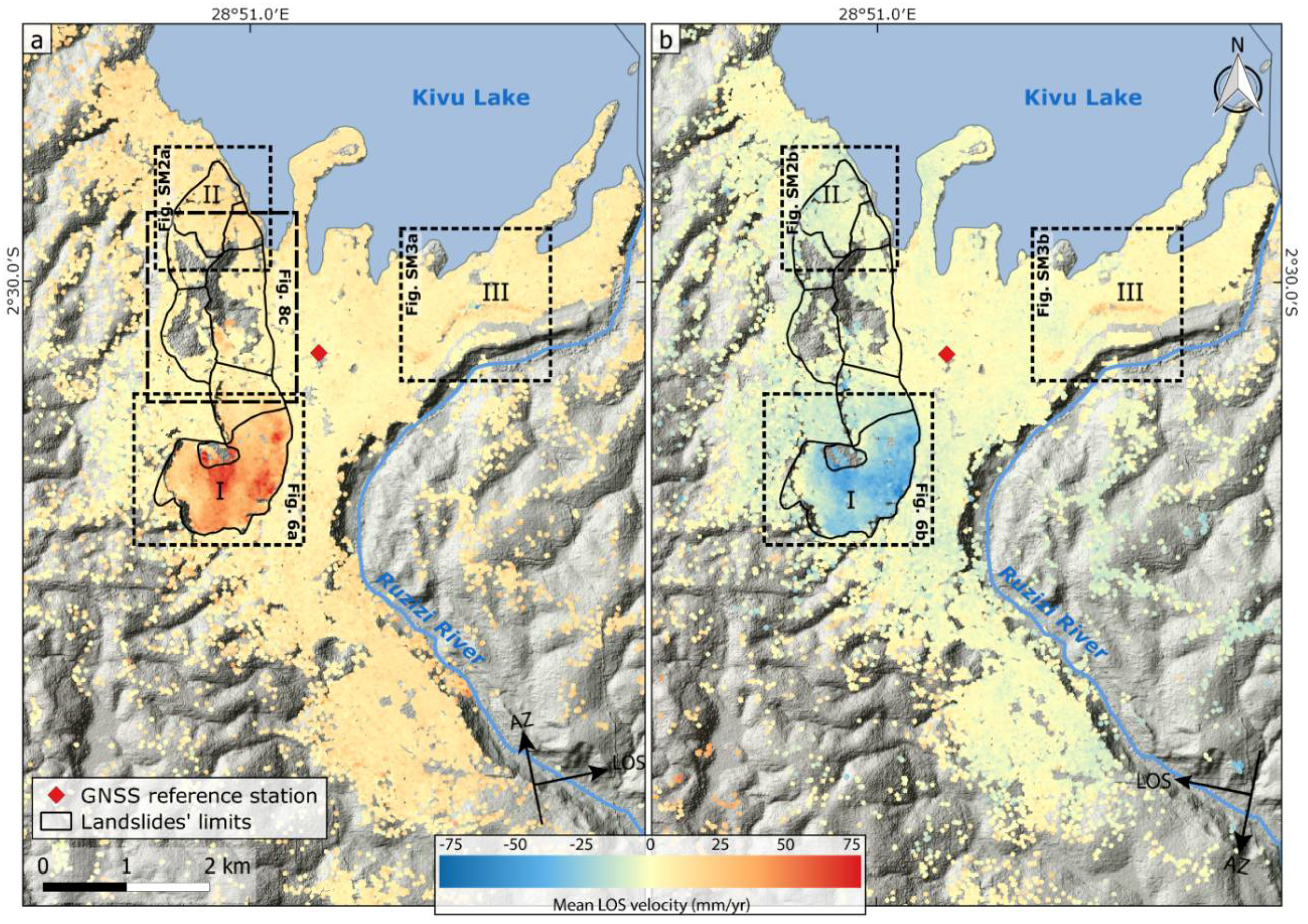
The ground deformation maps over Bukavu obtained from the DInSAR processing are shown in Figure 4. On these maps, ground deformation measures are mostly available in the urbanized areas, with no, or only few, measurements over vegetated or bare environment due to loss of coherence. In those urbanized areas, the dense habitat and communication network indeed provide an important number of permanent scatters where deformation information can be gathered. Similar deformation patterns are observed with both ascending and descending datasets.
Figure 5 shows the data used for the evaluation of the DInSAR measurement accuracy. The area (1 km2) where these values were gathered surrounds the location of the reference BUK station (Figure 3). This zone is showing a low signal to noise ratio and includes both steep and flat terrain that reflects the conditions found over the entire study site. Over this stable area, the mean deformation rates measured by DInSAR is ~4 mm/year in ascending and ~0 mm/year in descending LOS, with a standard deviation of ±4 mm/year for both passes. This value of the standard deviation is here assumed to reflect the accuracy in displacement rate obtained at the different individual permanent scatters found over the study area.
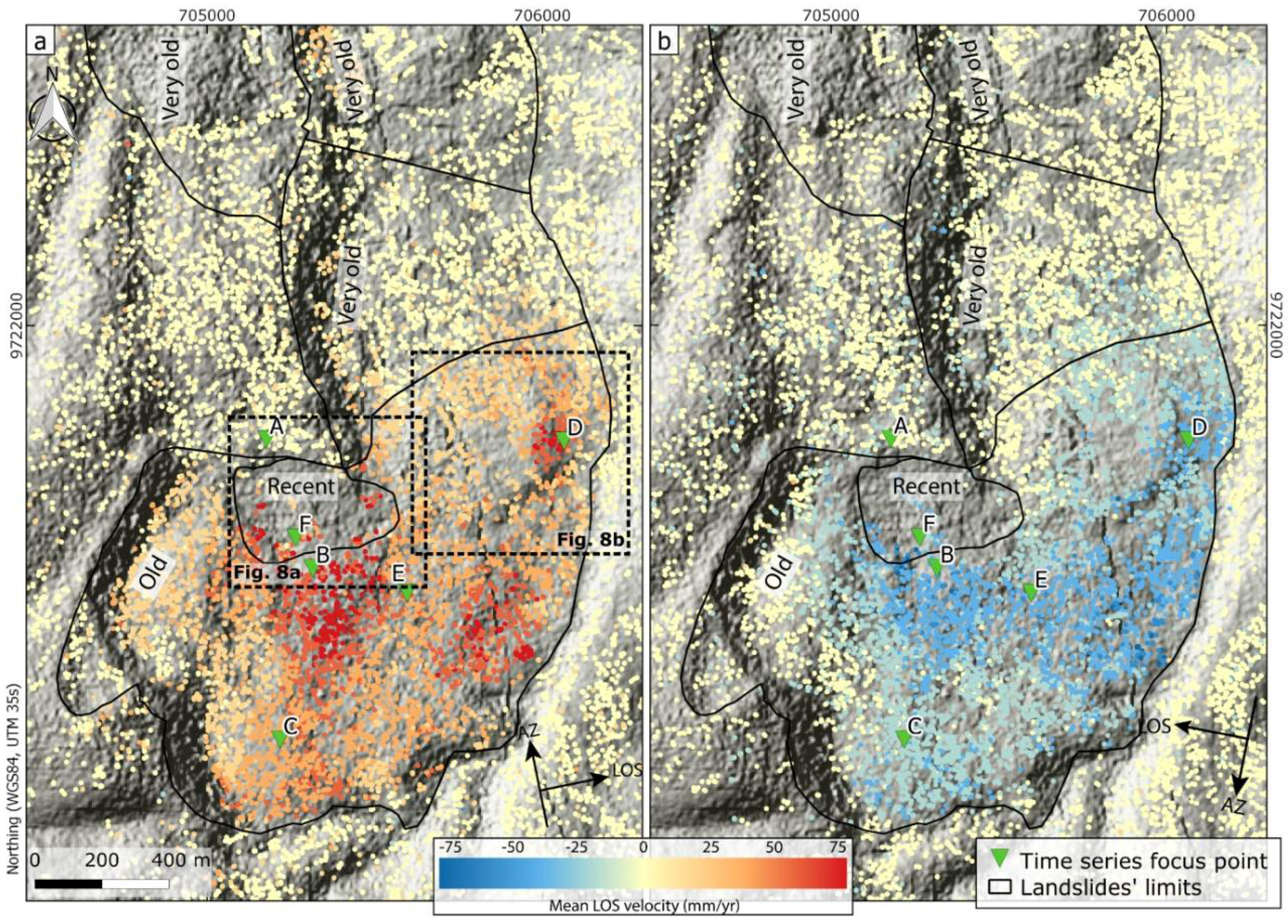
Three zones showing a high signal to noise ratio in Figure 4 should be mentioned. Zone I clearly stands out (see also zoom in Figure 6), being shown as affected by important deformation rates both in the ascending and descending datasets. The analysis of the displacement shows that the movement of the slope is principally eastward (since the displacement values show opposite signs in the different looking geometries; with a range increase for the ascending LOS and a range decrease for the descending LOS). This should, however, not mask the importance of the vertical component of displacement (subsidence), highlighted by the generally higher deformation rates estimated from the ascending pass than the one obtained from the processing of the descending dataset. The deformation maps show that the large active slide of 1.5 km2 comprises several sectors characterised by different displacement rates, with an amplitude in absolute value ranging from ~10 ± 4 mm/year up to more than 75 ± 4 mm/year in the two LOS directions. Zone II (see also zoom in Figure S2), shows a moderate to high (even if less clear than in Zone I) signal to noise ratio. This area, located along Lake Kivu, shows a movement of the ground away from the satellite (10 ± 4 mm/year) for the ascending LOS and a movement towards the satellite (−6 ± 4 mm/year) in the descending LOS. Additionally, here, the movement is principally eastwarding. An elongated zone close to the Ruzizi River forms a third zone of interest (Zone III, see also zoom in S2). This zone shows a clear signal in range increase, i.e., a movement away from the satellite, for both looking geometries (up to 55 ± 4 mm/year and 33 ± 4 mm/year for the ascending and descending LOS, respectively). This movement is principally vertical and in subsidence.

4.2. Comparison of DInSAR Ground Deformations to the Landslide Inventory

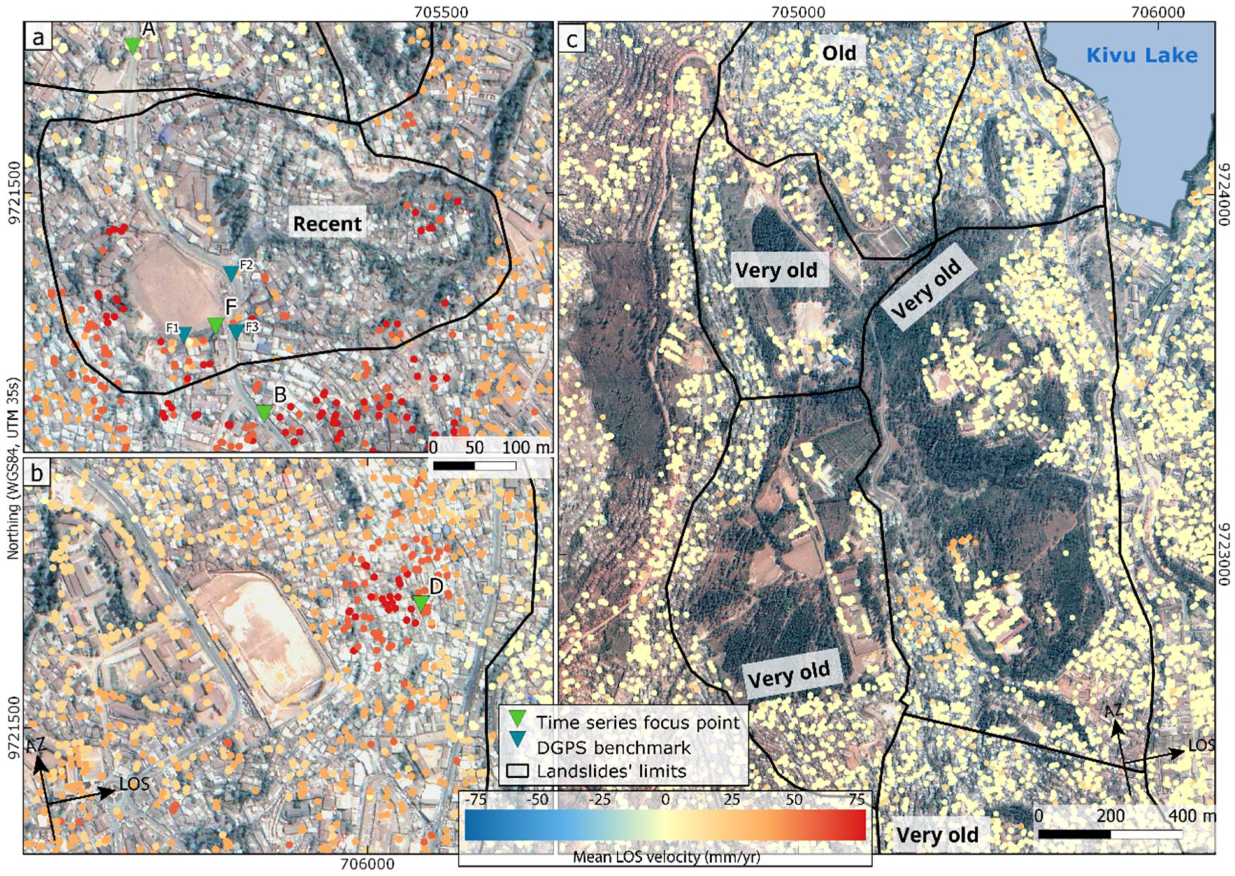
For the area where the landslide inventory was assembled for validation, Figure 4 shows that, at first sight, DInSAR deformations match pretty well with what was observed. The landslides identified as the eldest features appear with very little displacements while the recent ones are more active. Zooms on the hillslope (Zone I, see Figure 6) confirm that the DInSAR measurements correspond well to field reality, the limits of the delineated landslides corresponding to the deformation patterns. Within this large unstable slope, some areas are affected by deformation fast enough to overrun the spatio-temporal resolution of the method (i.e., deformation inducing more than half a fringe per pixel). In these areas, no DInSAR deformation measurements could be obtained over a sector delineated as a follow-up to recent and active landslides (Figure 6). This landslide seems to move faster than the neighbouring areas, as attested in the field by the number of fractures affecting houses and roads, and bending trees.
Over Zone II, that is facing Lake Kivu in the northern part of the hillslope, was also delineated a relatively recent landslide (classified as old) that is known to be currently affected by ground deformation. The strength of the DInSAR derived displacement signal observed on Figure S2 over this area is, however, less strong, with a mean rate of 11 ± 4 mm/year and −6 ± 4 mm/year recorded in ascending and descending LOS, respectively.

4.3. Comparison of DInSAR Ground Deformations to DGPS Measurements

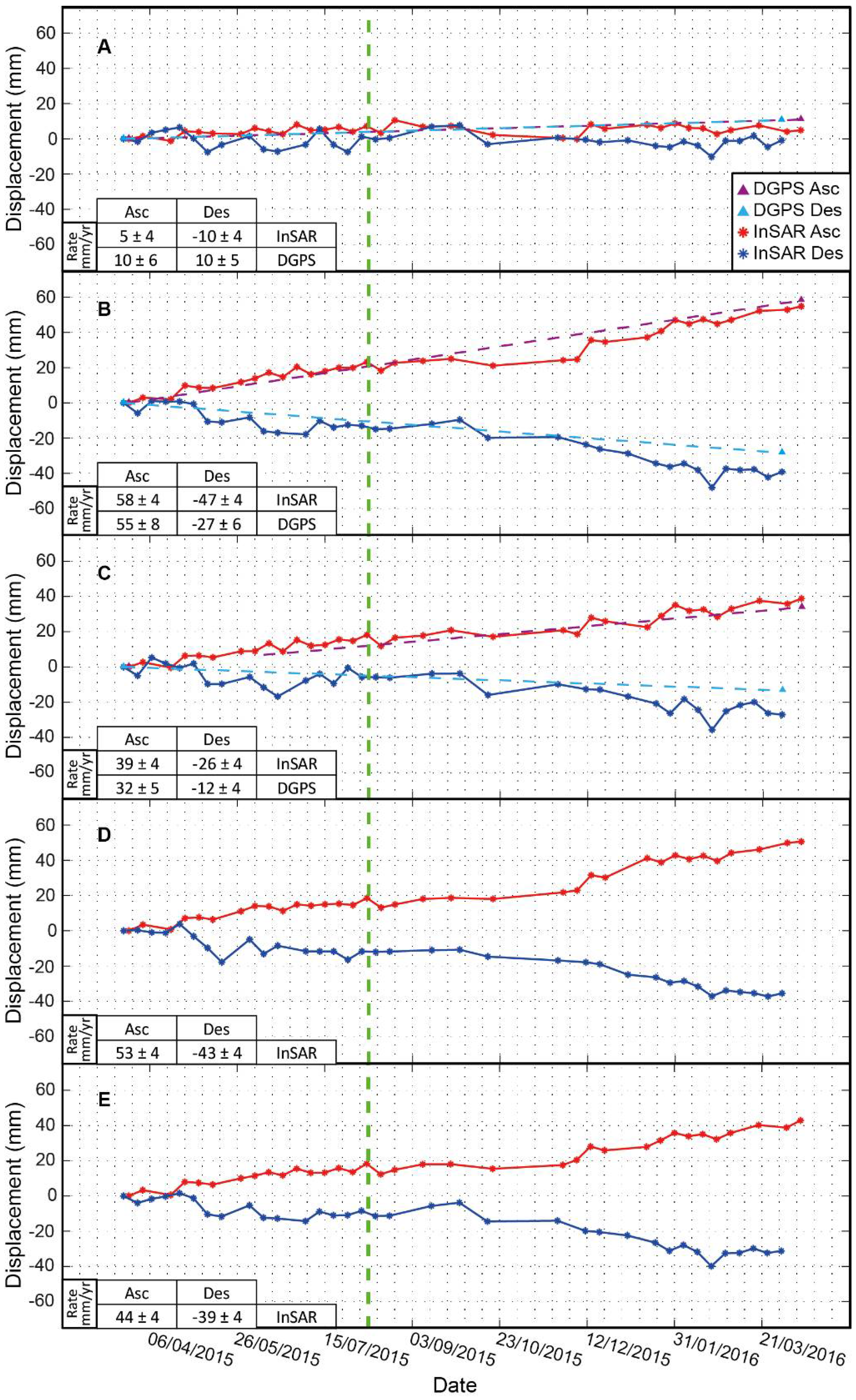
For a quantitative validation of the ground deformations, we compared the time series of displacement obtained from DInSAR to those gathered by DGPS in and outside the 1.5 km2 landslide. Ground deformation time series (Figure 7) were extracted for five representative points, of which three correspond to the location of DGPS benchmarks (Figure 6). To reduce the noise in the DInSAR deformation measurements and check the stability and consistency of the points used in the evaluation of the time series of deformation, we considered the average displacement obtained for all permanent scatters included within a radius of 25 m from each of these points.
Point A is located outside the landslide and shows a relatively stable behaviour with a displacement rate of 5 ± 4 mm/year and −10 ± 4 mm/year captured from DInSAR in ascending and descending passes, respectively. While the ascending signal is consistent with the displacement assessed by the DGPS measurements (10 ± 6 mm/year) given the uncertainties of both methods (Figure 6a) the descending signal shows an opposite trend to the DGPS (10 ± 5 mm/year). This can be explained by the non-linearity observed for the DGPS measurements at this benchmark (Figure S1). Points B to E are located within the active landslide parts. Overall, they show the same deformation trend with, however, a difference in amplitude. The DInSAR—DGPS comparison in points B and C shows a good agreement, with differences included within the error margin. Point B, for instance, which belongs to one of the fastest-moving blocks of the landslide, shows a yearly velocity of 58 ± 4 mm/year from DInSAR and 55 ± 4 mm/year from DGPS in ascending LOS and −47 ± 4 mm/year from DInSAR and −27 ± 7 mm/year from DGPS in descending LOS over the period studied. When converted into horizontal and vertical components, the DInSAR displacement rate corresponds to a movement towards the east of ~72 mm/year and a subsidence of ~13 mm/year. Similar differences are observed for point C, with DInSAR displacement rate of 39 ± 4 mm/year and −26 ± 4 mm/year and DGPS displacement rate of 32 ± 5 mm/year and −12 ± 4 mm/year for ascending and descending LOS, respectively. Converted in horizontal and vertical displacement, those rates correspond to a movement of 45 mm/year towards the east and 13 mm/year in subsidence. Overall, the time series obtained from DInSAR show steady displacement variations, with a linear correlation coefficient >0.8.
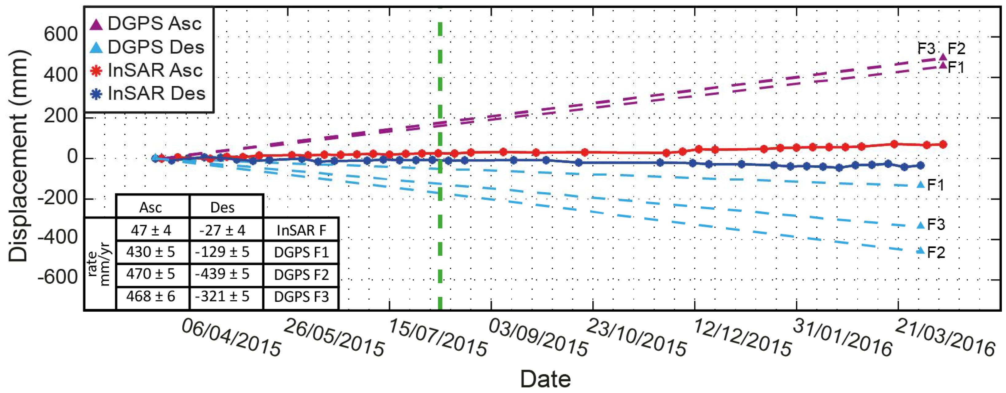
The area covered by Figure 8a corresponds to a recent and active follow-up landslide that is included within the large 1.5 km2 slide. We compared the displacement rates captured by three other DGPS benchmarks (F1 to F3) with the few DInSAR coherent pixels found over the surrounding area. Over this zone, DGPS data show displacement rates up to 500 mm/year, which is about eight times higher than the displacements from DInSAR (47 ± 4 mm/year in ascending LOS and −27 ± 4 mm/year in descending LOS, see Figure 9).

5. Discussion

5.1. Reliability of DInSAR Measurements

Here, characteristics of the study area, such as the high density of permanent scatters related to the dense urban fabric, the relatively low velocity of the ground deformations, and the general eastward movement of the surface deformation features made the city of Bukavu an ideal site for the use of DInSAR techniques. Nevertheless, the high atmospheric variability associated with the tropical environment call for giving special attention to the measurements accuracy and validation of the DInSAR results. The accuracy of the DInSAR displacement measurements was evaluated through a statistical estimation of the residual phase noise (Figure 5). The value of ±4 mm/year obtained for both looking geometries is of the same magnitude as those obtained in other studies (e.g., [57,59]). In addition, we followed a two-step validation procedure combining DGPS measurements and field observations that attests to the reliability of the measurements obtained from DInSAR and of the capability of the technique to grasp the deformation pattern affecting this complex tropical-urban environment.
InSAR data highlighted a large (~1.5 km2) deep-seated and slow-moving landslide as the main instability affecting the wide hillslope located on the south-west of the city (Figures 4). This deformation feature was also delineated in the field-based inventory used in the validation procedure, geomorphological mapping recognising this landslide as the (relatively) most recent and active landslide over the hillslope. Within this large landslide, the deformation rate maps (Figure 6) highlight the capability of the technique to capture subtle differences in displacement velocity over the slope, also stressing the complexity of this large active slide. The quantitative validation has also highlighted the quality of the DInSAR products, a good correlation being shown between the velocities measured by DInSAR and those obtained from DGPS measurements (Figure 7) over this landslide. The small discrepancies observed are within the error margin of both techniques.
Moreover, it is worth mentioning that DGPS measurements are point-based, while the DInSAR-derived rates are averages over the coherent targets located within a 25 m radius around each DGPS benchmark. Even if the time series and rates are consistent for all the coherent pixels in the area, the small-scale heterogeneity captured by DInSAR also impacts the averaged rate used for the comparison and thus increases the discrepancies.
Ground deformations detected by DInSAR in zone II (Figure S2) shows deformation rates of about 11 ± 4 mm/year in ascending LOS and −6 ± 4 mm/year in descending LOS. Similarly to the large 1.5 km2 landslide, this zone was mapped in the inventory also used for validation as an old landslide with some parts currently active. On the contrary to the latter, whose major displacement component is directed towards the east, the movement of the landslide in zone II is mainly oriented towards the northeast. This topographic context could explain an underestimation of the actual landslide deformation with DInSAR; this method being ineffective to measure a north–south component of a slope movement. Ancillary data, such as DGPS measurements, could help to further characterize this.

5.2. DInSAR Deformation Time Series and Landslide Processes

The dense deformation history recorded by the DInSAR time series is another important product of the processing. Active landslides can exhibit a seasonal movement pattern that is primarily governed by precipitation and groundwater levels [11,63,64,65]. Here, the time series over this slow-moving landslide shows that it was moving at a nearly steady rate over the entire studied period (12 months), no cyclic trend in the displacement rate being recorded for that specific period (Figure 7). Another natural potential factor that could affect the displacement rates of active landslides is seismicity (e.g., [66,67,68,69,70]). The city of Bukavu is commonly affected by earthquakes [41,42,71,72] and the Mw 5.8 August 2015 earthquake with the epicentre located ~40 km north of the centre of Bukavu ([52]—Figure 1) could have potentially affected the slope stability over the city [70,73,74,75]. The displacement time series in Figure 7, however, show no change (anticipated it could be acceleration) in the deformation rates after this event. A similar absence of velocity change was recorded by DGPS measurements obtained a few days before and after the August 2015 earthquake (Figure S1). A factor that could have potentially decreased the effect of the earthquake on the slope deformation velocity is its occurrence during the dry season.
We are aware that we have to handle these results with caution since we are in an urban context and anthropogenic activities could play a role on the landslide activity. For example, the presence of houses, roads, and sewage systems can increase, locally, the water concentration, but, on average, a decrease of the total amount of infiltrating water is expected over the landslide. It must also be highlighted that the absence of records of cyclic trends or abrupt changes that would show a relationship between landslide processes and climatic or seismic triggers could be linked to the relatively short length (one year) of the time series used. The expansion of the time series presented here would be of great value to confirm this absence or reveal trends that affect the landslide kinematics only over longer timeframes.

5.3. Limitations of the DInSAR Technique for Landslide Characterisation

Zone III (Figure S3) is moving locally up to 50 ± 4 mm/year in ascending LOS and 33 ± 4 mm/year in descending LOS, with a major displacement component showing a subsidence. This relatively important deformation is affecting an almost flat area where no landslides were mapped nor reported. Moreover, this area does not have a contrasting soil/lithology from the surroundings that could explain this local deformation by, for instance, a tendency to compaction. Here, the recent and rapid urbanisation of the area can probably explain the observed deformation [76,77]. This area remained cultivated until the early 2000s, while the neighbour zones were urbanized in the 1950s. The effect of overloading (compaction) potentially combined with drainage/water pumping can explain the deformation signal recorded by DInSAR. This signal confirms the well-known ability of DInSAR to capture deformations of various origin. This signal also emphasises the need of different LOS to understand the direction of movement and multi-sensors/-techniques approaches to limit the risk of false landslide detection.
The present study also highlights another type of limitation of the technique: the limit in the maximum detectable displacement. In particular, the fastest surface movements in Zone I, which corresponds to a recent follow-up landslide within the large 1.5 km2 slide, is not fully captured by DInSAR (Figure 6 and Figure 8a). DGPS measurements (benchmarks F1 to F3, Figure 9) show that the movement of the scatters over this relatively rapid landslide can be of at least ~16 mm (half of the sensor wavelength; the limit before a phase jump) in about 13 days, assuming a constant displacement rate. While the fairly high temporal sampling of the CSK SAR image acquisitions (~8 days) should, in theory, allow the capture of such deformation, the need for keeping a small spatial baseline (<400 m) led to the coupling of images with longer temporal baselines (up to 96 days). In addition, the areas directly surrounding this follow-up landslide, although also continuously moving, show displacement rates of nearly an order of magnitude lower (e.g., benchmark B, located ~85 m away from F3, shows displacements up to 2 mm over the same period). Both conditions imply a phase difference between coherent neighbour pixels higher than 2π, leading either to a loss of coherence or an underestimation of the displacement during the unwrapping of the interferograms. The use of the C-band ESA Sentinel-1 (λ ≈ 51.2 mm), with 12 days revisiting time and spatial baseline <200 m between subsequent acquisitions, is expected to allow the full capture of the movement [20]. The low revisit frequency of Sentinel-1 before early 2017 (24 to 48 days) over the region of interest, however, did not allow a comparison with CSK results, but calls for future work over the area.
Finally, the suitability of the urban environment for the use of DInSAR stated previously also highlights, by opposition, the limit of the technique in other land cover contexts, such as vegetated areas or bare reworked soils, where direct coherence loss and absence of measurements are observed. Figure 8 shows examples of zones where coherence was lost because of the land cover. In Figure 8a,b large, flat, clay courts appear totally lacking of measurable coherent targets (in a, the high displacement rate also playing a role in the loss of coherence), while in c the correlation between vegetation and the absence of measurements is clear.

6. Conclusions

We show that the multi-temporal DInSAR technique can be used to characterise ground deformations associated with landslides in the city of Bukavu. Using the SBAS approach, we produce displacement rate maps and ground deformation time series to identify various landslide processes of different ages, mechanisms and state of activity. The accuracy of the DInSAR deformation rates in this complex dual combination of urban and tropical contexts is estimated to ~4 mm/year; a value consistent with what is usually found in the literature and, in this specific case, probably in large part associated with the unstable atmospheric properties observed in the tropics. In addition, ground deformation revealed by DInSAR are found consistent with field observations and DGPS measurements. However, longer time series will be needed to infer any potential landside response to climate, seismic, or anthropogenic drivers.
The dense urban fabric, the relatively low velocity of the ground deformations, and the general eastward topography make the city of Bukavu a particularly interesting site for the use of DInSAR techniques. Furthermore, the densely populated context over this study area makes the study of the landslide hazard, and so the appraisal of the performance of methods for its characterisation, more relevant than ever for the society.

Supplementary Materials

The following are available online at https://www.mdpi.com/2072-4292/10/4/626/s1, Figure S1. DGPS time series for the period January 2015–October 2016; Figure S2. Ground deformation maps and time series for Zone II; Figure S3. Ground deformation maps and time series for Zone III.

Acknowledgments

Financial support came from BELSPO for RESIST (SR/00/305), MODUS (SR/00/358), AfReSlide (BR/121/A2/AfReSlide) and GeoRisCA (SD/RI/02A) research projects (http://resist.africamuseum.be/, http://afreslide.africamuseum.be/, http://georisca.africamuseum.be/) and the Belgian Development Cooperation (DGD) for the S1_RGL_GEORISK project. COSMO-SkyMed images were provided to the RESIST project under an Italian Space Agency (ASI) licence. Advice given by Edward Glawe has been a great help in DGPS post-processing. Special thanks go to Université Officielle de Bukavu, and particularly to the members of the Department of Geology. They provided useful information on landslide occurrences, and made it possible to execute fieldwork in the study area. We are also grateful to the Institut Supérieur Pédagogique of Bukavu, the authorities of the City of Bukavu and Civil Protection of South Kivu for their logistic support. Finally, we would like to thank the three anonymous reviewer who provided fast and detailed reviews to improve the manuscript.

Author Contributions

Olivier Dewitte, François Kervyn, Nicolas d’Oreye, and Adriano Nobile conceived and designed the study; Adriano Nobile processed the SAR data and analysed the results; Antoine Dille and Nicolas d’Oreye contributed to the interpretation of InSAR results. Elise Monsieurs, Olivier Dewitte, François Kervyn, Joseph Basimike, and Toussaint Mugaruka Bibentyo participated in the field data acquisition and interpretation; Elise Monsieurs processed the DGPS data and analysed the results with Adriano Nobile; and Adriano Nobile, Antoine Dille, and Olivier Dewitte drafted the paper. All the authors contributed to the final version of the paper.

Conflicts of Interest

The authors declare no conflict of interest.

References

  1. Jacobs, L.; Dewitte, O.; Poesen, J.; Delvaux, D.; Thiery, W.; Kervyn, M. The Rwenzori Mountains, a landslide-prone region? Landslides 2016, 13, 519–536. [Google Scholar] [CrossRef]
  2. Kirschbaum, D.; Stanley, T.; Zhou, Y. Spatial and temporal analysis of a global landslide catalog. Geomorphology 2015, 249, 4–15. [Google Scholar] [CrossRef]
  3. Monsieurs, E.; Kirschbaum, D.; Thiery, W.; van Lipzig, N.; Kervyn, M.; Demoulin, A.; Jacobs, L.; Kervyn, F.; Dewitte, O. Constraints on Landslide-Climate Research Imposed by the Reality of Fieldwork in Central Africa. In Proceedings of the 3rd North American Symposium Landslides, Landslides: Putting Experience, Knowledge and Emerging Technologies into Practice, Roanoke, VA, USA, 4–8 June 2017; pp. 158–168. [Google Scholar]
  4. Petley, D. Global patterns of loss of life from landslides. Geology 2012, 40, 927–930. [Google Scholar] [CrossRef]
  5. Sidle, R.C.; Ziegler, A.D.; Negishi, J.N.; Nik, A.R.; Siew, R.; Turkelboom, F. Erosion processes in steep terrain—Truths, myths, and uncertainties related to forest management in Southeast Asia. For. Ecol. Manag. 2006, 224, 199–225. [Google Scholar] [CrossRef]
  6. DeFries, R.S.; Rudel, T.; Uriarte, M.; Hansen, M. Deforestation driven by urban population growth and agricultural trade in the twenty-first century. Nat. Geosci. 2010, 3, 178–181. [Google Scholar] [CrossRef]
  7. Gariano, S.L.; Guzzetti, F. Landslides in a changing climate. Earth-Sci. Rev. 2016, 162, 227–252. [Google Scholar] [CrossRef]
  8. Maes, J.; Kervyn, M.; de Hontheim, A.; Dewitte, O.; Jacobs, L.; Mertens, K.; Vanmaercke, M.; Vranken, L.; Poesen, J. Landslide risk reduction measures: A review of practices and challenges for the tropics. Prog. Phys. Geogr. 2017, 41, 191–221. [Google Scholar] [CrossRef]
  9. Knapen, A.; Kitutu, M.G.; Poesen, J.; Breugelmans, W.; Deckers, J.; Muwanga, A. Landslides in a densely populated county at the footslopes of Mount Elgon (Uganda): Characteristics and causal factors. Geomorphology 2006, 73, 149–165. [Google Scholar] [CrossRef]
  10. Schulz, W.H.; Coe, J.A.; Ricci, P.P.; Smoczyk, G.M.; Shurtleff, B.L.; Panosky, J. Landslide kinematics and their potential controls from hourly to decadal timescales: Insights from integrating ground-based InSAR measurements with structural maps and long-term monitoring data. Geomorphology 2017, 285, 121–136. [Google Scholar] [CrossRef]
  11. Bennett, G.L.; Roering, J.J.; Mackey, B.H.; Handwerger, A.L.; Schmidt, D.A.; Guillod, B.P. Historic drought puts the brakes on earthflows in Northern California. Geophys. Res. Lett. 2016, 43, 5725–5731. [Google Scholar] [CrossRef]
  12. Schlögel, R.; Doubre, C.; Malet, J.P.; Masson, F. Landslide deformation monitoring with ALOS/PALSAR imagery: A D-InSAR geomorphological interpretation method. Geomorphology 2015, 231, 314–330. [Google Scholar] [CrossRef]
  13. Stumpf, A.; Malet, J.-P.; Delacourt, C. Correlation of satellite image time-series for the detection and monitoring of slow-moving landslides. Remote Sens. Environ. 2017, 189, 40–55. [Google Scholar] [CrossRef]
  14. Reiche, J.; Lucas, R.; Mitchell, A.L.; Verbesselt, J.; Hoekman, D.H.; Haarpaintner, J.; Kellndorfer, J.M.; Rosenqvist, A.; Lehmann, E.A.; Woodcock, C.E.; et al. Combining satellite data for better tropical forest monitoring. Nat. Clim. Chang. 2016, 6, 120–122. [Google Scholar] [CrossRef]
  15. Ferretti, A.; Prati, C.; Rocca, F. Permanent Scatters in SAR Interferometry. IEEE Trans. Geosci. Remote Sens. 2001, 39, 8–20. [Google Scholar] [CrossRef]
  16. Crosetto, M.; Monserrat, O.; Devanthéry, N.; Cuevas-González, M.; Barra, A.; Crippa, B. Persistent scatterer interferometry using Sentinel-1 data. Int. Arch. Photogramm. Remote Sens. Spat. Inf. Sci. ISPRS Arch. 2016, 41, 835–839. [Google Scholar] [CrossRef]
  17. Berardino, P.; Fornaro, G.; Lanari, R.; Sansosti, E. A new algorithm for surface deformation monitoring based on small baseline differential SAR interferograms. IEEE Trans. Geosci. Remote Sens. 2002, 40, 2375–2383. [Google Scholar] [CrossRef]
  18. Lanari, R.; Casu, F.; Manzo, M.; Zeni, G.; Berardino, P.; Manunta, M.; Pepe, A. An overview of the Small BAseline Subset algorithm: A DInSAR technique for surface deformation analysis. Pure Appl. Geophys. 2007, 164, 637–661. [Google Scholar] [CrossRef]
  19. Colesanti, C.; Wasowski, J. Investigating landslides with space-borne Synthetic Aperture Radar (SAR) interferometry. Eng. Geol. 2006, 88, 173–199. [Google Scholar] [CrossRef]
  20. Wasowski, J.; Bovenga, F. Investigating landslides and unstable slopes with satellite Multi Temporal Interferometry: Current issues and future perspectives. Eng. Geol. 2014, 174, 103–138. [Google Scholar] [CrossRef]
  21. Raspini, F.; Bardi, F.; Bianchini, S.; Ciampalini, A.; Del Ventisette, C.; Farina, P.; Ferrigno, F.; Solari, L.; Casagli, N. The contribution of satellite SAR-derived displacement measurements in landslide risk management practices. Nat. Hazards 2017, 86, 327–351. [Google Scholar] [CrossRef]
  22. Bovenga, F.; Pasquariello, G.; Pellicani, R.; Re, A.; Spilotro, G. Landslide monitoring for risk mitigation by using corner reflector and satellite SAR interferometry: The large landslide of Carlantino (Italy). Catena 2017, 151, 49–62. [Google Scholar] [CrossRef]
  23. Mirzaee, S.; Motagh, M.; Akbari, B.; Wetzel, H.U.; Roessner, S. Evaluating Three InSAR Time-Series Methods To Assess Creep Motion, Case Study: Masouleh Landslide in North Iran. ISPRS Ann. Photogramm. Remote Sens. Spat. Inf. Sci. 2017, IV-1/W1, 223–228. [Google Scholar] [CrossRef]
  24. Bayer, B.; Simoni, A.; Mulas, M.; Corsini, A.; Schmidt, D. Deformation responses of slow moving landslides to seasonal rainfall in the Northern Apennines, measured by InSAR. Geomorphology 2018. [Google Scholar] [CrossRef]
  25. Prati, C.; Ferretti, A.; Perissin, D. Recent advances on surface ground deformation measurement by means of repeated space-borne SAR observations. J. Geodyn. 2010, 49, 161–170. [Google Scholar] [CrossRef]
  26. Hooper, A.; Bekaert, D.; Spaans, K.; Arikan, M. Recent advances in SAR interferometry time series analysis for measuring crustal deformation. Tectonophysics 2012, 514–517, 1–13. [Google Scholar] [CrossRef]
  27. Bekaert, D.P.S.S.; Walters, R.J.; Wright, T.J.; Hooper, A.J.; Parker, D.J. Statistical comparison of InSAR tropospheric correction techniques. Remote Sens. Environ. 2015, 170, 40–47. [Google Scholar] [CrossRef]
  28. Bovenga, F.; Wasowski, J.; Nitti, D.O.; Nutricato, R.; Chiaradia, M.T. Using COSMO/SkyMed X-band and ENVISAT C-band SAR interferometry for landslides analysis. Remote Sens. Environ. 2012, 119, 272–285. [Google Scholar] [CrossRef]
  29. Notti, D.; Davalillo, J.C.; Herrera, G.; Mora, O. Assessment of the performance of X-band satellite radar data for landslide mapping and monitoring: Upper Tena Valley case study. Nat. Hazards Earth Syst. Sci. 2010, 10, 1865–1875. [Google Scholar] [CrossRef] [Green Version]
  30. Calò, F.; Ardizzone, F.; Castaldo, R.; Lollino, P.; Tizzani, P.; Guzzetti, F.; Lanari, R.; Angeli, M.G.; Pontoni, F.; Manunta, M. Enhanced landslide investigations through advanced DInSAR techniques: The Ivancich case study, Assisi, Italy. Remote Sens. Environ. 2014, 142, 69–82. [Google Scholar] [CrossRef]
  31. Cigna, F.; Bateson, L.B.; Jordan, C.J.; Dashwood, C. Simulating SAR geometric distortions and predicting Persistent Scatterer densities for ERS-1/2 and ENVISAT C-band SAR and InSAR applications: Nationwide feasibility assessment to monitor the landmass of Great Britain with SAR imagery. Remote Sens. Environ. 2014, 152, 441–466. [Google Scholar] [CrossRef]
  32. Milillo, P.; Fielding, E.J.; Shulz, W.H.; Delbridge, B.; Burgmann, R. COSMO-skymed spotlight interferometry over rural areas: The slumgullion landslide in Colorado, USA. IEEE J. Sel. Top. Appl. Earth Obs. Remote Sens. 2014, 7, 2919–2926. [Google Scholar] [CrossRef]
  33. Novellino, A.; Cigna, F.; Sowter, A.; Ramondini, M.; Calcaterra, D. Exploitation of the Intermittent SBAS (ISBAS) algorithm with COSMO-SkyMed data for landslide inventory mapping in north-western Sicily, Italy. Geomorphology 2017, 280, 153–166. [Google Scholar] [CrossRef]
  34. Elliott, J.R.; Walters, R.J.; Wright, T.J. The role of space-based observation in understanding and responding to active tectonics and earthquakes. Nat. Commun. 2016, 7, 13844. [Google Scholar] [CrossRef] [PubMed]
  35. Crosetto, M.; Copons, R.; Cuevas-González, M.; Devanthéry, N.; Monserrat, O. Monitoring soil creep landsliding in an urban area using persistent scatterer interferometry (El Papiol, Catalonia, Spain). Landslides 2018, 1983. [Google Scholar] [CrossRef]
  36. Moeyersons, J.; Tréfois, P.; Lavreau, J.; Alimasi, D.; Badriyo, I.; Mitima, B.; Mundala, M.; Munganga, D.O.; Nahimana, L. A geomorphological assessment of landslide origin at Bukavu, Democratic Republic of the Congo. Eng. Geol. 2004, 72, 73–87. [Google Scholar] [CrossRef]
  37. Trefois, P.; Moeyersons, J.; Lavreau, J.; Alimasi, D.; Badryio, I.; Mitima, B.; Mundala, M.; Munganga, D.O.; Nahimana, L. Geomorphology and urban geology of Bukavu (R.D. Congo): Interaction between slope instability and human settlement. Geol. Soc. Lond. Spec. Publ. 2007, 283, 65–75. [Google Scholar] [CrossRef]
  38. Michellier, C.; Delvaux, D.; D’Oreye, N.; Dewitte, O.; Havenith, H.-B.; Kervyn, M.; Poppe, S.; Trefon, T.; Wolff, E.; Kervyn, F. Geo-Risk in Central Africa: Integrating Multi-Hazards and Vulnerability to Support Risk Management; Final Report; Belgian Science Policy: Brussels, Belgium, 2018; pp. 1–186. [Google Scholar]
  39. Michellier, C.; Pigeon, P.; Kervyn, F.; Wolff, E. Contextualizing vulnerability assessment: A support to geo-risk management in central Africa. Nat. Hazards 2016, 82, 27–42. [Google Scholar] [CrossRef]
  40. Eriksen, H.Ø.; Lauknes, T.R.; Larsen, Y.; Corner, G.D.; Bergh, S.G.; Dehls, J.F. Visualizing Surface Displacement Patterns Using Multi-Geometry Satellite SAR Interferometry. Remote Sens. Environ. 2017, 191, 297–312. [Google Scholar] [CrossRef]
  41. D’Oreye, N.; González, P.J.; Shuler, A.; Oth, A.; Bagalwa, L.; Ekström, G.; Kavotha, D.; Kervyn, F.; Lucas, C.; Lukaya, F.; et al. Source parameters of the 2008 Bukavu-Cyangugu earthquake estimated from InSAR and teleseismic data. Geophys. J. Int. 2011, 184, 934–948. [Google Scholar] [CrossRef] [Green Version]
  42. Delvaux, D.; Mulumba, J.-L.; Sebagenzi, M.N.S.; Bondo, S.F.; Kervyn, F.; Havenith, H.-B. Seismic hazard assessment of the Kivu rift segment based on a new seismotectonic zonation model (western branch, East African Rift system). J. Afr. Earth Sci. 2016. [Google Scholar] [CrossRef]
  43. Hooper, A.J. A multi-temporal InSAR method incorporating both persistent scatterer and small baseline approaches. Geophys. Res. Lett. 2008, 35, 1–5. [Google Scholar] [CrossRef]
  44. Biggs, J.; Wright, T.; Lu, Z.; Parsons, B. Multi-interferogram method for measuring interseismic deformation: Denali Fault, Alaska. Geophys. J. Int. 2007, 170, 1165–1179. [Google Scholar] [CrossRef]
  45. Ding, X.L.; Li, Z.W.; Zhu, J.J.; Feng, G.C.; Long, J.P. Atmospheric effects on InSAR measurements and their mitigation. Sensors 2008, 8, 5426–5448. [Google Scholar] [CrossRef] [PubMed]
  46. Zebker, H.A.; Villasenor, J. Decorrelation in Inteferometric Radar Echoes. IEEE Trans. Geosci. Remote Sens. 1992, 30, 950–959. [Google Scholar] [CrossRef]
  47. Crosetto, M.; Monserrat, O.; Cuevas-González, M.; Devanthéry, N.; Crippa, B. Persistent Scatterer Interferometry: A review. ISPRS J. Photogramm. Remote Sens. 2016, 115, 78–89. [Google Scholar] [CrossRef]
  48. Hooper, A.; Bekaert, D.; Spaans, K. StaMPS/MTI Manual; School of Earth and Environment, University of Leeds: Leeds, UK, 2013. [Google Scholar]
  49. Farr, T.G.; Kobrick, M. Shuttle radar topography mission produces a wealth of data. EOS Trans. Am. Geophys. Union 2000, 81, 583–585. [Google Scholar] [CrossRef]
  50. Goldstein, R.M.; Werner, C.L. Radar interferogram filtering for geophysical applications. Geophys. Res. Lett. 1998, 25, 4035–4038. [Google Scholar] [CrossRef]
  51. Hooper, A.; Zebker, H.A. Phase unwrapping in three dimensions with application to InSAR time series. J. Opt. Soc. Am. A 2007, 24, 2737. [Google Scholar] [CrossRef]
  52. Geirsson, H.; d’Oreye, N.; Mashagiro, N.; Syauswa, M.; Celli, G.; Kadufu, B.; Smets, B.; Kervyn, F. Volcano-tectonic deformation in the Kivu Region, Central Africa: Results from six years of continuous GNSS observations of the Kivu Geodetic Network (KivuGNet). J. Afr. Earth Sci. 2016. [Google Scholar] [CrossRef]
  53. Burgmann, R.; Rosen, P.A.; Fielding, E.J. Synthetic Aperture Radar Interferometry to Measure Earth’s Surface Topography and its Defromation. Annu. Rev. Earth Planet. Sci. 2000, 28, 169–209. [Google Scholar] [CrossRef]
  54. Hanssen, R.F. Radar Interferometry: Data Interpretation and Error Analysis; Springer Science & Business Media: Berlin, Germany, 2001; ISBN 0-7923-6945-9. [Google Scholar]
  55. Seimon, A.; Phillipps, P.G. Regional climatology of the Albertine rift. In Long-Term Changes in Africa’s Rift Valley: Impacts on Biodiversity and Ecosystems; Nova Science Publishers Inc.: Hauppauge NY, USA, 2011; pp. 9–30. ISBN 9781611227802. [Google Scholar]
  56. Thiery, W.; Davin, E.L.; Panitz, H.-J.; Demuzere, M.; Lhermitte, S.; van Lipzig, N. The Impact of the African Great Lakes on the Regional Climate. J. Clim. 2015, 28, 4061–4085. [Google Scholar] [CrossRef] [Green Version]
  57. González, P.J.; Fernández, J. Error estimation in multitemporal InSAR deformation time series, with application to Lanzarote, Canary Islands. J. Geophys. Res. 2011, 116, B10404. [Google Scholar] [CrossRef]
  58. Quin, G.; Loreaux, P. Submillimeter Accuracy of Multipass Corner Reflector Monitoring by PS Technique. IEEE Trans. Geosci. Remote Sens. 2013, 51, 1775–1783. [Google Scholar] [CrossRef]
  59. Anderssohn, J.; Motagh, M.; Walter, T.R.; Rosenau, M.; Kaufmann, H.; Oncken, O. Surface deformation time series and source modeling for a volcanic complex system based on satellite wide swath and image mode interferometry: The Lazufre system, central Andes. Remote Sens. Environ. 2009, 113, 2062–2075. [Google Scholar] [CrossRef]
  60. Hungr, O.; Leroueil, S.; Picarelli, L. The Varnes classification of landslide types, an update. Landslides 2014, 11, 167–194. [Google Scholar] [CrossRef]
  61. Malet, J.-P.; Maquaire, O.; Calais, E. The use of Global Positioning System techniques for the continuous monitoring of landslides. Geomorphology 2002, 43, 33–54. [Google Scholar] [CrossRef]
  62. Dodo, J.D.; Yahya, M.H.; Kamarudin, M.N. Investigation on the Impact of Tropospheric Delay on GPS Height Variation near the Equator. Afr. J. Inf. Commun. Technol. 2008, 4, 73–79. [Google Scholar] [CrossRef]
  63. Handwerger, A.L.; Roering, J.J.; Schmidt, D.A. Controls on the seasonal deformation of slow-moving landslides. Earth Planet. Sci. Lett. 2013, 377–378, 239–247. [Google Scholar] [CrossRef]
  64. Handwerger, A.L.; Roering, J.J.; Schmidt, D.A.; Rempel, A.W. Kinematics of earthflows in the Northern California Coast Ranges using satellite interferometry. Geomorphology 2015, 246, 321–333. [Google Scholar] [CrossRef]
  65. Schulz, W.H.; McKenna, J.P.; Kibler, J.D.; Biavati, G. Relations between hydrology and velocity of a continuously moving landslide-evidence of pore-pressure feedback regulating landslide motion? Landslides 2009, 6, 181–190. [Google Scholar] [CrossRef]
  66. Keefer, D.K. The importance of earthquake-induced landslides to long-term slope erosion and slope-failure hazards in seismically active regions. Geomorphology 1994, 10, 265–284. [Google Scholar] [CrossRef]
  67. Zerathe, S.; Lacroix, P.; Jongmans, D.; Marino, J.; Taipe, E.; Wathelet, M.; Pari, W.; Smoll, L.F.; Norabuena, E.; Guillier, B.; et al. Morphology, structure and kinematics of a rainfall controlled slow-moving Andean landslide, Peru. Earth Surf. Process. Landf. 2016, 41, 1477–1493. [Google Scholar] [CrossRef]
  68. Lacroix, P.; Berthier, E.; Maquerhua, E.T. Earthquake-driven acceleration of slow-moving landslides in the Colca valley, Peru, detected from Pléiades images. Remote Sens. Environ. 2015, 165, 148–158. [Google Scholar] [CrossRef]
  69. Lacroix, P.; Perfettini, H.; Taipe, E.; Guillier, B. Coseismic and postseismic motion of a landslide: Observations, modeling, and analogy with tectonic faults. Geophys. Res. Lett. 2014, 41, 6676–6680. [Google Scholar] [CrossRef]
  70. Keefer, D.K. Investigating landslides caused by earthquakes—A historical review. Surv. Geophys. 2002, 23, 473–510. [Google Scholar] [CrossRef]
  71. Smets, B.; Delvaux, D.; Ross, K.A.; Poppe, S.; Kervyn, M.; d’Oreye, N.; Kervyn, F. The role of inherited crustal structures and magmatism in the development of rift segments: Insights from the Kivu basin, western branch of the East African Rift. Tectonophysics 2016, 683, 62–76. [Google Scholar] [CrossRef]
  72. Oth, A.; Barrière, J.; d’Oreye, N.; Mavonga, G.; Subira, J.; Mashagiro, N.; Kadufu, B.; Fiama, S.; Celli, G.; Bigirande, J.; et al. KivuSNet: The First Dense Broadband Seismic Network for the Kivu Rift Region (Western Branch of East African Rift). Seismol. Res. Lett. 2017, 88, 49–60. [Google Scholar] [CrossRef]
  73. Tatard, L.; Grasso, J.R. Controls of earthquake faulting style on near field landslide triggering: The role of coseismic slip. J. Geophys. Res. Solid Earth 2013, 118, 2953–2964. [Google Scholar] [CrossRef]
  74. Meunier, P.; Hovius, N.; Haines, J.A. Topographic site effects and the location of earthquake induced landslides. Earth Planet. Sci. Lett. 2008, 275, 221–232. [Google Scholar] [CrossRef]
  75. Meunier, P.; Uchida, T.; Hovius, N. Landslide patterns reveal the sources of large earthquakes. Earth Planet. Sci. Lett. 2013, 363, 27–33. [Google Scholar] [CrossRef]
  76. Chen, G.; Zhang, Y.; Zeng, R.; Yang, Z.; Chen, X.; Zhao, F.; Meng, X. Detection of Land Subsidence Associated with Land Creation and Rapid Urbanization in the Chinese Loess Plateau Using Time Series InSAR: A Case Study of Lanzhou New District. Remote Sens. 2018, 10, 270. [Google Scholar] [CrossRef]
  77. Pratesi, F.; Tapete, D.; Del Ventisette, C.; Moretti, S. Mapping interactions between geology, subsurface resource exploitation and urban development in transforming cities using InSAR Persistent Scatterers: Two decades of change in Florence, Italy. Appl. Geogr. 2016, 77, 20–37. [Google Scholar] [CrossRef]
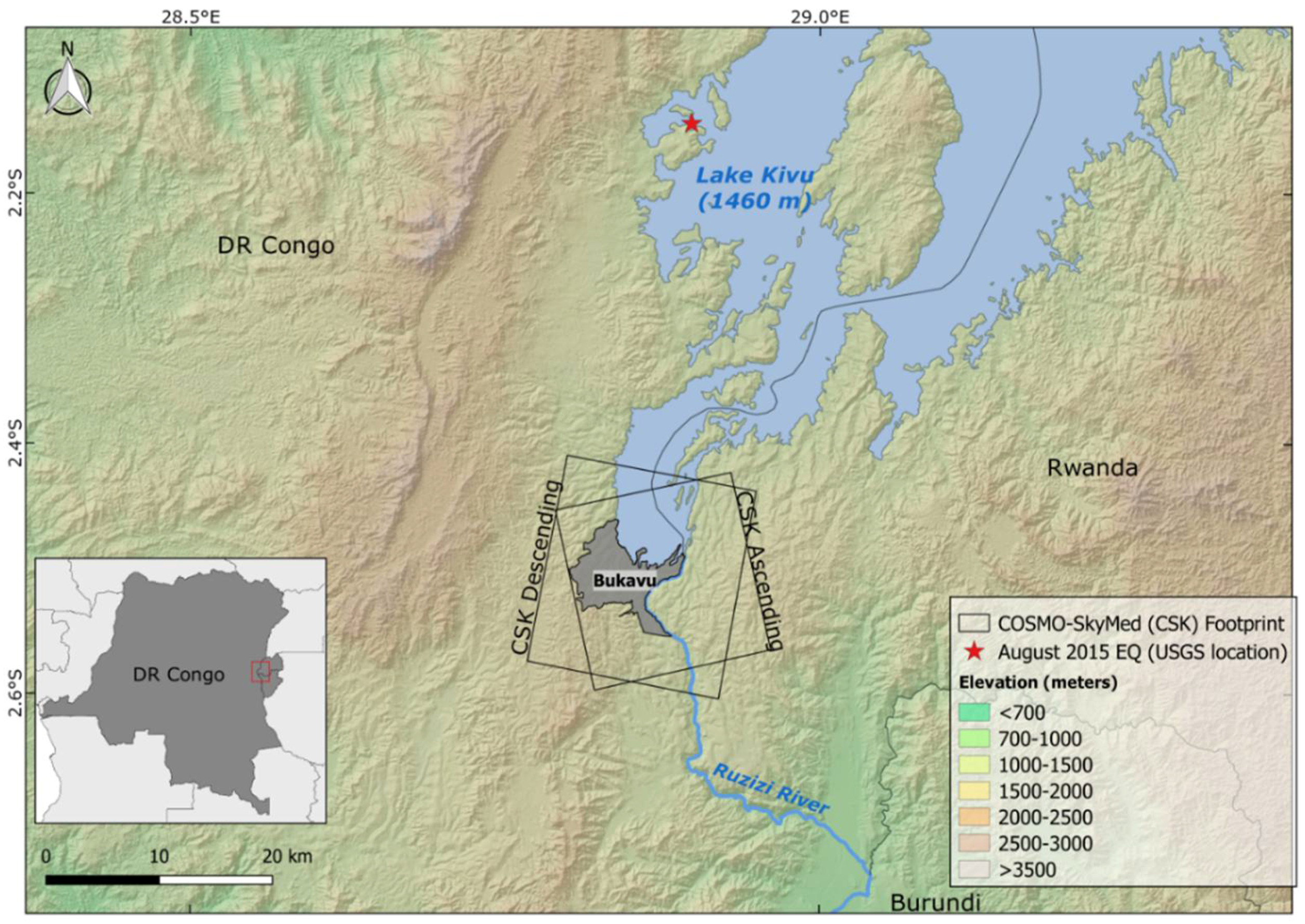
Figure 1. Location of the city of Bukavu (grey area) and its close surroundings (red rectangle in the insert). Black rectangles show the cropped footprints of CSK acquisitions for both ascending and descending orbits. The red star shows the epicentre of the Mw 5.8 August 2015 earthquake (USGS location).
Remotesensing 10 00626 g001
Figure 2. Spatial and temporal baselines of the interferograms processed for both the ascending (red) and descending (blue) COSMO-SkyMed datasets. Images were acquired between 21 March 2015 and 19 April 2016 with a mean revisit time of eight days per orbit (with a gap of ~40 days between October and November 2015). A total of 121 interferograms with short temporal (<64 days) and spatial (<400 m) baselines were processed. For the descending orbit, two interferograms with longer temporal baseline (80 and 96 days) were added to avoid gaps in the chain of interferograms. Few SAR images (three) were rejected, both for registration issues and due to non-matching of baseline parameters. The green dashed line corresponds to the occurrence of the Mw 5.8 August 2015 earthquake.
Remotesensing 10 00626 g002
Figure 3. (a) Limit and relative age of the landslides inventoried over the large hillslope. The red diamond represents the position of the BUK GNSS station (Kivu-G-Net; [52]). The 1 km2 circle corresponds to the area selected to evaluate the DInSAR measurements accuracy while the violet diamonds represent the locations of pictures (b,c). Those pictures show views of the large 1.5 km2 landslide (Zone I) where validation through comparison of DGPS measurements and DInSAR results is carried out. Both pictures highlight the main escarpment of this large slide. (b) The view from the top taken in August 2015. (c) The view taken in February 2014 in the direction of the main escapement over a recent follow-up landslide located within the large 1.5 km2 slide. These pictures highlight the dense urban context of Bukavu, and particularly of the large 1.5 km2 landslide. Notice also the dense presence of metallic roofs that constitute good radar scatters.
Remotesensing 10 00626 g003
Figure 4. Deformation rate maps in the radar line-of-sight (LOS) for the ascending (a) and descending (b) CSK datasets. InSAR measures displacements along LOS direction, those have to be interpreted as a one-dimensional component of the full 3-D displacement vector (e.g., [40]). Combining at least two different looking geometry vectors allows to evaluate the vertical and E–W component of the displacement. Here, a red colour corresponds to a movement away from the satellite while a blue towards the satellite. The red diamond corresponds to the BUK station considered as the stable reference point. Rectangles correspond to the zoom in Figure 6 and Figure 8c, SM2 and SM3. The zones I, II, and III are zones affected by important deformation and described in the text.
Remotesensing 10 00626 g004
Figure 5. The circles (a,b) show deformation rates for all the coherent pixels within the 1 km2 zone (Figure 3) used to evaluate the accuracy of the InSAR measurements for the ascending (~2900 pixels) and descending (~3200 pixels) LOS, respectively. Over this area considered as stable, the InSAR deformation signal obtained is very small (for both LOS); variations in the signal amplitude are, thus, mainly related to noise. The histograms show the frequency distribution of the displacement rate of the different pixels.
Remotesensing 10 00626 g005
Figure 6. Zoom over the large 1.5 km2 active slide of Funu (Zone I). (a) shows deformation rates for the ascending and (b) the descending orbit. Points A to F (green triangles) correspond to the location of the extracted displacement time series shown in Figure 7 and Figure 9. The two rectangles correspond to zooms in Figure 8a,b while the black lines show the outline of the landslides inventoried in the field.
Remotesensing 10 00626 g006
Figure 7. InSAR displacement time series for five focus points (AE) in both ascending and descending LOS (location shown in Figure 6). Points A to C also correspond to the locations of DGPS benchmarks, their respective recorded rates are shown. The InSAR and DGPS yearly rates are provided in the insert when available. The green dashed line corresponds to the occurrence of the August 2015 seismic sequence.
Remotesensing 10 00626 g007
Figure 8. Ground deformation maps obtained from DInSAR (ascending LOS) draped over a high-resolution Pléiades image. (a) The absence of measurements is observed over the recent and fast-moving follow-up landslide. A combination of several factors can explain the latter: presence of vegetation and bare reworked soil, as well as the rapid displacements observed (measured through DGPS to up to ~550 mm/year eastward and ~240 mm/downward—blue triangles F1, F2, F3). (b) shows the lack of scatters observed over a large, flat, clay court (the football stadium). (c) highlights the impact of the (dense) vegetation on the conservation of the coherence.
Remotesensing 10 00626 g008
Figure 9. Displacement time series obtained from DInSAR and DGPS (benchmarks F1, F2, F3) over focus point F located within the recent follow-up landslide (Figure 8a). In addition to the presence of only a few pixels providing InSAR-derived deformation information (Figure 8a), an important (factor 10) difference between the measured DGPS and InSAR displacement rates is observed (see insert). The relatively high velocity of the displacement (rates up to 470 ± 5 mm/year according to DGPS) compared to the sensor wavelength imply a phase difference between coherent neighbour pixels higher than 2π, leading either to a loss of coherence or an underestimation of the displacement during the unwrapping of the interferograms.
Remotesensing 10 00626 g009