1. Introduction
The use of renewable energy sources like solar and wind power has led to a lot of research into better ways to control these sources. This helps make sure that they are stable, efficient, and strong [
1]. Among the different wind energy (WE) conversion systems, the doubly fed induction generator (DFIG) coupled with a multi-rotor wind turbine (DFIG-MRWT) has become a top technology because it can adjust its speed and capture more energy [
2]. As the complexity of these systems increases, traditional control methods often struggle to balance performance with robustness amidst nonlinear dynamics, parameter uncertainties, and fluctuating wind conditions [
3]. Consequently, innovative control frameworks—particularly those leveraging artificial intelligence—have garnered significant attention [
4]. Given the importance of renewable energies such as photovoltaic solar power and wind turbines, several evaluation studies have been conducted, including [
5]. This study evaluates the performance of photovoltaic solar power systems, wind turbines, and concentrated solar power (CSP) in Morocco. The technical potential of photovoltaic solar power, CSP, and wind power was examined in three Moroccan locations, Midelt, Dakhla, and Laayoune, using meteorological data and forecasting models validated using Southern Oscillation Matrix (SAM) estimates. The results demonstrate high solar potential, with photovoltaic solar power capacity factors ranging between 22% and 24%, strong performance in CSP, and excellent wind power generation in Dakhla and Laayoune, with Laayoune performing best in this respect. The advantages include the ease and reliability of modeling and the provision of clear guidelines for deploying hybrid renewable energy systems. The disadvantages lie in the reliance on model data rather than measured field data, which may affect the accuracy of the results.
Controlling energy consumption and production is a key focus in renewable energy systems. Therefore, predicting energy consumption is crucial to avoiding peak demand and grid disruptions. In [
6], the authors conducted a predictive study of household energy consumption and its analysis, integrating it with renewable energy sources. This predictive study was conducted using machine learning algorithms for energy management. Machine learning-based models were used to predict household energy consumption in an IoT-enabled smart home, utilizing sensor data (temperature, humidity, and appliance usage) and time-series techniques such as ARIMA and LSTM. The logistic regression model performed best among the tested machine learning models for characteristic-based prediction, while the time-series models provided accurate estimates of future consumption. This approach enables more efficient energy use and better demand planning, but it involves complex data processing and intensive model training. Therefore, intelligent control strategies are crucial for improving the performance and efficiency of renewable energy systems, especially wind power. Wind power relies primarily on wind turbines. These wind turbines can be classified as horizontal-axis or vertical-axis turbines [
7,
8]. Horizontal-axis wind turbines are the most widespread and commonly used onshore and offshore. These turbines are constantly evolving, with recent years witnessing the emergence of a new technology called multi-rotor wind turbines (MRWTs).
The use of MRWT systems represents an important step toward improving the sustainability of WE conversion. By distributing aerodynamic loads across several smaller rotors instead of relying on a single large rotor, multi-rotor configurations reduce structural mass, material usage, and transportation constraints while enabling higher overall energy capture efficiency. This modular architecture can lower manufacturing costs, simplify maintenance through component-level replacement, and minimize mechanical stress on individual drivetrain elements, thereby extending system lifetime and decreasing lifecycle environmental impact. Moreover, multi-rotor systems offer improved scalability and land use flexibility, which supports higher renewable penetration with optimized resource utilization. However, the sustainability benefits of such architectures depend strongly on the implementation of efficient and robust control systems. Because MRWTs involve complex aerodynamic interactions and coupled electrical dynamics, advanced control strategies are necessary to ensure stable power sharing, minimize torque oscillations, and maintain grid compliance under variable wind and disturbance conditions. Efficient control reduces energy losses, enhances power quality (PQ), and prevents excessive mechanical loading, directly contributing to longer component lifespan and lower maintenance demand. Robust and adaptive controllers further improve resilience against uncertainties and extreme operating conditions, ensuring reliable renewable energy delivery. Therefore, the combination of MRWT technology with intelligent, high-performance control systems is not only advantageous but essential for maximizing energy yield, operational reliability, and long-term sustainability of modern WE installations.
1.1. Literature Survey
A review of the extant literature on control strategies for DFIG-based wind energy systems (WESs) reveals a broad spectrum of methods, ranging from classical proportional–integral (PI) regulators to advanced robust and adaptive techniques [
9]. Conventional PI controls are widely applied due to their simplicity but exhibit limitations under highly nonlinear conditions and parameter variations [
10]. To address these shortcomings, researchers have explored model predictive control [
11], fuzzy logic [
12], and sliding mode control (SMC) [
13] to enhance stability and dynamic response. Recently, scientists have started using a type of artificial intelligence called a “neural network” to deal with the complexities and unknowns that come with wind turbine systems [
14]. These intelligent regulators offer adaptive learning capabilities that can approximate complex system dynamics without requiring precise mathematical models [
15].
Traditionally, NNs have become a powerful and widespread tool in everything from control systems to new energy, increasing their capabilities in reading nonlinear messages, learning, and adapting. In control systems, NNs are prominently used to improve the performance of robust, nonlinear regulators, particularly SMC-type control, by approximating unknown dynamics, compensating for uncertainties, and mitigating the effects of oscillation, resulting in smoother control operations and improved stability margins [
16,
17]. Ref. [
18] proposes a Neural Tuning Machine (NTM)-augmented PI regulator for controlling a DFIG in grid-connected WE systems. In this context, the NTM ensemble dynamically tunes the PI gains to improve performance in comparison with conventional PI, adaptive neuro-fuzzy inference system (ANFIS)-PI, and NN-PI regulators. In the baseline PI regulator, the proportional gain (Kp) was around 0.82–0.85 with an integral gain (Ki) of 4.2–5.0, yielding a response time of about 6.53 ms, a maximum overshoot of 17.08%, and sluggish performance under load changes. The implementation of the proposed NTM approach yielded substantial enhancements in performance metrics. The maximum overshoot was reduced to approximately 8.23%, and the settling time was decreased to approximately 0.93 s. These observations suggest that the approach led to a more optimal transient response and increased stability. The NTM-PI regulator demonstrated superior performance in under-voltage fluctuation tests at the point of common coupling when compared to benchmark controllers. The NTM-PI regulator exhibited an R
2 fit of approximately 0.911–0.930 and a reduced root mean square error (RMSE) of 0.067–0.073. Additionally, it exhibited enhanced accuracy and sensitivity metrics. However, the designed approach has several drawbacks: the neural tuning ensemble, while improving adaptability, introduces substantial model complexity and tuning overhead, requiring careful configuration of recurrent networks and dense plexus connections. The training process also risks overfitting, as indicated by total harmonic distortion (THD)-related RMSE variations at different epochs, and relies on extensive data preprocessing and ensemble training procedures. Additionally, the method’s performance validation is limited to simulation under steady conditions, with no real-time implementation or hardware verification, and the impact of changing wind profiles or grid disturbances beyond the tested scenarios remains unexamined. However, the work [
19] suggests a smart control plan for systems that convert WE using a special type of machine called a DFIG-based wind turbine generator (WTG). This plan combines a Chaotic Salp Swarm Optimization (CSSO)-tuned ANFIS for maximum power point tracking (MPPT) with a coordinated rotor-side converter (RSC) and grid-side converter (GSC) control framework to improve voltage stability and power extraction performance. Simulation results show that the CSSO-ANFIS MPPT achieves a very high tracking efficiency of 99.86%, with the fastest MPPT response time of 0.08 s, significantly outperforming methods such as Modified Particle Swarm Optimization (M-PSO, 3.4 s) and Improved Gray Wolf Optimizer (I-GWO) (0.24 s). Coordinated control also provides improved grid support features, delivering low harmonic distortion with grid current THD < 2.85% and AC voltage THD ≈ 2.11%, and a stable power factor close to unity under both constant and variable wind conditions. Despite these promising results, the designed approach has several drawbacks: it relies heavily on complex CSSO and ANFIS training, which increases computational load and design complexity; the reliance on tuned neuro-fuzzy parameters can increase the risk of overfitting and requires careful dataset preparation and parameter selection; and validation is limited to MATLAB/Simulink (2021b) simulations without real-time implementation or hardware experiments to assess performance under practical uncertainties and measurement noise.
In the context of renewable energy systems, NNs find extensive application in multiple domains. These include MPPT control, PQ optimization, and transformer control. The integration of NNs facilitates efficient power extraction and ensures robust operation under rapidly changing environmental conditions. Such conditions include variations in solar radiation and wind speed (WS) [
20,
21,
22,
23,
24]. Moreover, they are extensively employed in energy forecasting, encompassing photovoltaic power generation and load prediction, thereby enhancing energy management systems and facilitating grid integration [
25,
26]. The study [
27], conducted across applications of NNs, specifically focuses on the control of a T-type break-in point inverter for a grid-connected solar power system using an artificial neural network controller (ANNC). The study concentrates on a transformer less T-type break-in point inverter designed for grid-connected photovoltaic solar power systems and proposes an ANNC to optimize its performance. The key results show that the T-type design reduces leakage current and common-mode voltage compared to conventional neutral point inverters without a transformer. The ANNC maintains DC link voltage stability under varying solar irradiance and minimizes the THD of the injected current through pulse-width modulation (PWM) control using a space vector. Advantages include lower switching and connection losses, improved PQ, and better dynamic response than conventional PI controllers. However, this approach relies on extensive NN training, increasing control complexity and potentially increasing the design effort and computational load in real-time implementation. Work [
28] addresses the detection of fault locations in hybrid power transmission systems connected to renewable energy sources using microwaves and artificial neural networks (ANNs). A method is designed that utilizes microwaves and ANNs to accurately pinpoint fault locations in long transmission lines, integrating conventional and renewable energy sources. Using detailed microwave parameters from current signals to train and test the ANN, the system detects fault locations within approximately half a cycle under various conditions and impedances in a simulated four-bus system. The results demonstrate high accuracy and robustness under different fault initiation angles and renewable energy generator capacities. The key advantage is the ability to quickly and reliably locate faults in complex hybrid networks; however, this method relies on precise extraction of microwave characteristics and NN training, which increases computational complexity. The research paper completed in [
29] presents adaptive prediction of solar power generation using an enhanced NN with weather data modification. This paper introduces a novel forecasting approach that combines an enhanced ANN with real-world weather data to improve the accuracy of solar power forecasting. By incorporating weather data modification and leveraging past forecasts, the proposed model significantly outperforms traditional statistical forecasting methods and machine learning techniques with real-world solar power generation data, achieving a reduction in root mean square error and competitive absolute mean error ratios. The advantages of this work include improved adaptation to changing weather conditions, leading to more reliable forecasts for the following day, and enhanced integration of solar energy into grid operations, supporting efficient renewable energy management. However, disadvantages include increased model complexity, the need for intensive data preprocessing, and higher computational requirements compared to simpler forecasting techniques, which may pose challenges for practical application in resource-constrained environments. Furthermore, NNs play a crucial role in fault diagnosis, systems modeling, and intelligent energy management in hybrid renewable energy systems, improving reliability and operational efficiency [
30,
31,
32,
33]. A new strategy [
34] has been developed to improve WE generation forecasting using advanced deep learning technology via a wavelet-enhanced recurrent NN and controlled linear modules. This forecasting model integrates wavelet-based signal processing, a recurrent NN, and controlled linear modules to enhance WE forecasting. The results indicate improved accuracy and better handling of nonlinear time patterns compared to simpler models. Advantages include improved forecast quality and adaptability to varying wind data, while disadvantages include increased model complexity and higher computational requirements for training and implementation. The present study [
35] investigates a neural network backstepping control (NN-BC) scheme tailored for an Oscillating Water Column (OWC) wave energy system to improve rotor speed regulation under nonlinear and disturbed conditions. In numerical simulations, the proposed NN-BC controller demonstrated a substantial improvement in performance in comparison to both PI control and traditional BC. In the context of actuator disturbance, the NN-BC demonstrated a noteworthy performance, attaining an Integral Squared Error (ISE) of 22.5433. This result is particularly noteworthy when contrasted with the ISEs of 40.6381 for PI and 37.1192 for BC, which underscores the NN-BC’s efficacy in rejecting disturbances and maintaining a smoother tracking of the rotational speed reference. Furthermore, it demonstrated the smallest maximum peak overshoot (approximately 0.9651 rad/s) and the fastest settling time (~0.0561 s) in comparison to both conventional approaches. The latter exhibited larger overshoot and slower convergence, particularly the PI regulator, with a considerably longer settling duration and higher transient error. These metrics highlight the NN-BC’s improved dynamic response and robustness against disturbances and nonlinearities inherent in WE conversion systems. However, the designed approach has a few drawbacks: the controller relies on a Chebyshev NN that requires careful training and tuning of network parameters; its performance is validated only in MATLAB/Simulink simulations without real-world or hardware experimental verification; and the optimization of controller parameters via Particle Swarm Optimization (PSO) adds an additional computational burden and dependency on optimizer quality. Furthermore, although NN-BC shows better performance than PI and BC, the lack of comparison with other advanced model-free or data-driven approaches leaves open questions about its relative efficiency under highly irregular sea states or real-time implementation constraints. These diverse applications demonstrate that NNs are becoming a key component in modern intelligent control frameworks for high-performance power electronics converters and renewable energy systems. In the aforementioned study [
36], the authors conducted a thorough comparison between reinforcement learning (RL) and ANN-based control strategies for inverter control in grid-connected photovoltaic systems. The study focused on performance metrics such as power output and PQ. The findings suggest that the RL controller demonstrates superior performance in comparison to the ANN approach across all evaluated scenarios. Specifically, it achieves an active power (
Ps) output of 100 kW, which is approximately 20% higher than the 82 kW output of the ANN regulator. This enhancement in power delivery to the grid is a notable advancement in the field. Furthermore, the RL controller generates a higher output current of 6 A in comparison to 4 A with ANN control, and demonstrates consistently lower THD for both current and voltage under ramp and random condition tests, thereby evidencing superior adaptability under dynamic environmental changes such as temperature and irradiance variations. Despite these improvements, the designed approach also has several drawbacks: the study is limited to simulation results without real-time or hardware validation, which may overlook practical issues such as measurement noise, communication delays, and computational latency; the ANN controller’s performance is reported only in comparison with RL, leaving uncertainty about how other advanced ANN architectures might perform; and the reinforcement learning method itself typically involves high training complexity, a need for large datasets, and potential convergence challenges, which may complicate implementation and tuning for real-world systems. Ref. [
37] experimentally validates a neural modified SMC (NMSMC) for a multi-rotor WT (MRWT) system driven by a double-powered induction generator, showing substantial performance improvements. The neural-based regulator demonstrated a significant reduction in overshoot, with a decrease of approximately 99.82% for reactive power (
Qs) and 97.26% for
Ps. Additionally, it exhibited a substantial improvement in current THD, reducing it by 48.80%, 46.35%, and 61.29%, as compared to the classical approach. Furthermore, the model demonstrated a reduction in
Ps ripples by approximately 81.35%, 85.20%, and 84.04%, thereby signifying enhanced power and current quality under both simulation and hardware-in-the-loop (dSPACE 1104) validation. However, the design’s drawbacks include increased control algorithm complexity due to neural integration and modified sliding mode logic, potential challenges in real-world tuning and scalability, and the need for further full hardware implementation beyond HIL to confirm robustness under varied real wind and grid disturbances. The study [
38] compares two DPC strategies for a doubly fed induction generator using a dSPACE-1104 controller board. The first strategy is conventional DPC, and the second strategy is DPC enhanced with a neural super-twisting algorithm (NSTA). In this strategy, PWM replaced hysteresis comparators to manage switching more effectively. Experimental results showed that the NSTA-based DPC significantly improved energy and current quality and minimized THD and power fluctuations compared with the traditional regulator under real-time conditions implemented on the dSPACE platform. However, the designed approach also has drawbacks: the NSTA controller increases algorithmic complexity and tuning effort, the additional control logic may demand higher computational resources on the real-time system, and validation remains focused on a specific experimental setup without broader testing under varied grid or wind disturbance profiles. The research paperin [
39] presents a new control strategy to improve the regulation of DC connection voltage for self-starting squirrel-cage generators, taking into account iron loss in wind-powered power conversion stations.This novel control strategy, which combines direct power control (DPC), type 2 fuzzy logic, and an improved pollination algorithm, enhances DC-link voltage regulation in wind turbine conversion systems. Simulation results demonstrate greater DC-link voltage stability and improved turbulence resistance compared to conventional control, resulting in better dynamic performance and increased robustness. Advantages include improved iron loss handling and adaptive control tuning, while disadvantages include increased control complexity and higher computational requirements. The study [
40] introduces a fractional-order neural control (FONC) for a 1.5 MW DFIG-driven MRWT, achieving 65.71% reduction in
Ps ripples and 84.74% in
Qs ripples, and improving overshoot by 71.33% and 91.72% compared to traditional DPC in simulations. However, there are some disadvantages. The system relies on simulation-only validation without experimental or real-time testing. It is also more complex because it combines fractional-order and NN control. There may be challenges in tuning and implementing it in the real world when there are different grid and wind disturbances. Ref. [
41] suggests using a neural synergetic super-twisting controller (NSSTC) to control the power of induction generators in variable-speed contra-rotating WT systems. Studies using simulations show that the NSSTC has better output PQ, lower rotor current THD, faster response time, and higher robustness compared to traditional DFOC-PI methods. However, numeric performance metrics such as exact THD reduction percentages and transient improvement values are not explicitly reported in the abstract, and the approach still relies on simulation validation rather than real-time or hardware implementation, potentially limiting insight into practical robustness, implementation complexity, and tuning overhead for real-world conditions. These diverse applications demonstrate that NNs are becoming a key component in modern intelligent control frameworks for high-performance power electronics converters and renewable energy systems.
Despite these advancements, few studies have systematically combined NN predictors with cascaded control architectures tailored specifically for DFIG-MRWT systems. Furthermore, much of the existing work focuses on either rotor-side or grid-side control in isolation, overlooking the potential synergy of an integrated cascaded neural control (CNC) scheme.
1.2. Key Research Gaps and Aims
Although NN control strategies have shown promise, significant gaps remain in the literature. First, existing NN controllers for DFIG-MRWT systems often lack a hierarchical structure, which limits their capacity to manage multiple control objectives concurrently, such as torque regulation, Qs compensation, and grid support. Second, there is a shortage of comprehensive studies evaluating the robustness of NN control schemes under varying wind profiles and grid disturbances. Third, the practical implementation challenges of NNs—including training efficiency, real-time adaptability, and stability guarantees—are seldom addressed in an integrated control framework.
This study tries to fix these problems by creating a special neural control design for the DFIG-MRWT system. The proposed plan uses the learning and approximation abilities of NNs while making sure that multiple subsystems and objectives are controlled at the same time. Although the proposed CNC method is being evaluated in comparison to the DPC-PI-GA strategy, several other advanced control techniques have been extensively studied for DFIG wind power conversion systems. In particular, SMC has received considerable attention due to its high robustness in the face of parameter uncertainties and disturbances [
42,
43]. Predictive model control (MPC) has also received considerable attention in power electronics converters due to its rapid dynamic response and ability to explicitly handle system constraints [
44]. Furthermore, intelligent control approaches based on NNs and fuzzy logic have been explored to improve the adaptability and nonlinear control performance of DFIG systems [
45,
46]. These methods provide important benchmarks in published studies and highlight the growing interest in advanced control strategies to improve the PQ, dynamic response, and robustness of grid-connected WE systems. In this context, the proposed numerical control approach aims to combine adaptive neural capabilities with a cascade control architecture to enhance ripple reduction, harmonic mitigation, and dynamic performance.
1.3. Motivation and Contributions
The impetus for this study is the pressing need to enhance the performance, robustness, and adaptability of WE conversion systems in the face of increased grid integration and resource variability. Conventional control systems are deficient in terms of adaptability to rapidly evolving dynamic conditions, necessitating extensive recalibration. The potential of neural networks to learn and generalize complex nonlinear mappings offers a significant opportunity to enhance control performance.
The principal contribution of this study is the development of a cascaded neural control method that integrates multiple learning-based controllers within a hierarchical structure to manage the doubly fed induction generator–multi-rotor torque (DFIG-MRT) system effectively. Specifically, this work contributes the following:
A novel cascaded control architecture that partitions control tasks into coordinated neural sub-controllers, improving overall system stability and dynamic response.
Enhanced robustness of the control strategy against wind turbulence and grid disturbances through adaptive learning mechanisms.
A comprehensive evaluation framework to assess performance improvements over classical and existing intelligent control approaches.
Table 1 presents a comparison of the designed approach with some related works, such as [
11,
23]. This work was compared with these works in terms of the type of controller used, degree of complexity, type of turbine used, operational performance, etc. Compared with predictive, fuzzy, sliding mode, and optimized fractional-order controllers reported in the recent literature, the proposed CNC strategy achieves a favorable compromise between control performance, robustness, and computational cost, while maintaining practical feasibility for real-time WE conversion system applications.
1.4. Objectives
To achieve these contributions, the key objectives of this research are as follows:
To design a cascaded control framework that integrates NN-based controllers for rotor-side subsystem of the DFIG-MRWT.
To develop adaptive training mechanisms that enable real-time learning and dynamic response to system uncertainties and external perturbations.
To assess the effectiveness of a newly proposed control architecture by means of simulation modeling in conjunction with comparative analysis with existing methods.
To demonstrate improved stability, robustness, and efficiency in power extraction and grid support under varying wind and grid conditions.
The following structure has been employed in the organization of this article. The initial section of the study provides a comprehensive overview of the research context, the underlying motivations for the study’s undertaking, and the study’s primary contributions. In
Section 2, the proposed power system is presented, including detailed mathematical models of the DFIG and the MRWT in
Section 2.1 and
Section 2.2, respectively. As delineated in
Section 3, the conventional DPC-PI control technique is utilized as a reference method for performance evaluation. In
Section 4, the proposed CNC method is introduced, and its structure and control principles are explained.
Section 5 represents a stability study of the approach designed based on the Budd curve.
Section 6 presents a comparative analysis of the CNC approach and the DPC-PI technique, with the objective of elucidating their relative performance. In
Section 7, the simulation and experimental results are presented and discussed.
Section 8 provides a comprehensive analysis of the primary limitations and disadvantages associated with the CNC strategy. Conclusively,
Section 9 of the paper synthesizes the salient findings and delineates potential avenues for future research.
2. Proposed Power System
The DFIG-based MRWT system is an advanced WE conversion architecture that integrates multiple WTs to maximize WE production. Only one generator is used to produce the power. The main components of this system include an MRWT-type turbine, gearboxes, DFIGs, RSC and GSC, a common DC connection, electrical transformers, and a supervisory control system responsible for power management. This setup has a few benefits, like better energy extraction, increased reliability, and less mechanical and electrical stress compared to single-rotor systems. By using multiple rotors, MRWTs can operate more efficiently under varying wind conditions and demonstrate better troubleshooting capabilities, since the failure of one rotor does not necessarily shut down the entire system.
In the renewable energy world, MRWT systems using DFIGs are becoming more and more important. They can control Ps and Qs in a flexible way, help keep the grid stable, and improve PQ overall. Furthermore, the use of MRWTs allows for expansion, reduced structural mass and more efficient use of land and materials, making them a promising solution for increasing reliance on WE while reducing costs and promoting sustainability.
The following provides a mathematical model of the most important basic components of the energy system under study.
2.1. DFIG Model
The DFIG model is frequently employed in WE conversion systems to illustrate the electrical and electromechanical characteristics of variable-speed wind turbines. The standard formulation of the system under consideration is in a synchronous dq reference frame. In this configuration, the stator is directly connected to the grid, while the rotor is interfaced through a back-to-back power electronic converter [
47]. This modeling approach enables the independent regulation of
Ps and
Qs by modulating the rotor currents. This approach accounts for machine dynamics, electromagnetic coupling, and mechanical effects. One of the main advantages of the DFIG in renewable energy applications is its ability to operate over a WS range with only a fraction of the total generated power processed by the converter, which significantly reduces converter size, losses, and cost [
48]. In addition, DFIG-based systems offer high efficiency, flexible power control, and effective grid support capabilities, such as
Qs compensation and voltage regulation [
49]. These features make the DFIG particularly suitable for large-scale WE integration, as it enhances energy capture, improves PQ, and contributes to the stability and reliability of modern electrical grids. The DFIG modeling is based on the Park transform. This transform is the most commonly used, providing equations for both the electrical and mechanical components [
50]. Equation (1) represents the mechanical component of the DFIG used in this paper [
51]. This equation controls the operation of the DFIG by either sending power to the grid or using power from the grid.
where
Te is the generator torque,
Tr is the load torque,
J is the inertia, and Ω is the speed.
The calculation of the generator torque can be performed using either the current or the flux. This torque is expressed by Equation (2) [
52].
The magnetic flux used to calculate the torque can be calculated using currents, for which Equation (3) is used [
50]. From Equation (3), the flux of the rotating part can also be calculated.
A dynamic machine such as the DFIG-type generator is connected to the grid via the stator and the rotor. Power is transmitted from the stator, and the generator is supplied from the rotor using three-phase voltages. The stator and rotor voltages are calculated using Equation (4) [
51].
2.2. MRWT Model
The MRWT model represents an advanced WE conversion concept in which several smaller rotors operate collaboratively on a single support structure and are electrically and/or mechanically coordinated to deliver power to the grid. The MRWT model typically includes the aerodynamic modeling of each rotor, the dynamic interactions among rotors, the associated generators, power converters, and a supervisory control system that ensures balanced power sharing and stable operation under variable wind conditions [
53]. One of the primary benefits of MRWTs in the domain of renewable energy is their capacity to augment overall energy capture by leveraging wind resources more effectively, particularly in low and non-uniform wind environments [
54]. By distributing aerodynamic loads across multiple rotors, MRWTs reduce structural stress, allow for lighter and more cost-effective support structures, and improve system reliability through inherent redundancy [
55]. Furthermore, MRWTs offer greater scalability and flexibility in design compared to single-rotor turbines, enabling easier transportation, installation, and maintenance [
56]. These advantages position MRWTs as a promising solution for increasing WE penetration while reducing costs and improving the sustainability and resilience of renewable energy systems.
In this work, an MRWT is employed to convert waste heat into mechanical energy. The turbine in question consists of two turbines. Consequently, the energy gained and the torque can be expressed in accordance with Equation (5) [
55].
In this system, “Pt” and “Tt” represent the total power and total torque, respectively. “T1” and “T2” denote the torque of the first and second WTs, while “P1” and “P2” represent the power of the first and second WTs, respectively.
The power output of each turbine is represented in Equation (6) [
55]. The power output of each turbine is contingent upon the WS, the turbine dimensions, and the distance between the turbines. Additionally, this power output is associated with a power coefficient (
Cp). This coefficient exerts a substantial influence on the power output, with the maximum power output being attained when this coefficient is equal to 1.
In this equation, ρ denotes the air density, Cp represents the coefficient of power, and S2 and S1 refer to the blade sweep surfaces of the second and first WTs, respectively.
As is well established, torque can be derived from power. Therefore, the torque value for each turbine can be calculated using Equation (6). Equation (7) represents the torque for each turbine. Equation (7) demonstrates that the torque value for each turbine is considerably influenced by the power coefficient and WS [
55]. The turbine’s dimensions also affect the torque value; a larger turbine will have a greater torque, and vice versa.
The value of the coefficient can be calculated using Equation (8). The coefficient in question has been demonstrated to be associated with both the pitch angle and the tip speed ratio.
where λ is the tip speed ratio and
β is the pitch angle.
In this paper, the tip speed ratio for each turbine is calculated using Equation (9) [
56]. This coefficient is greatly affected by WS. When WS is high, the tip speed ratio is low, and vice versa.
In the case of an MRWT system, the WS of the second turbine is expressed as the WS according to Equation (10) [
55,
56]. It is acknowledged that the WS of the initial turbine is equivalent to the WS, yet it deviates from the WS of the subsequent turbine. The operational speed of the turbines is contingent upon the distance (
x) between the two turbines.
The coefficient, denoted by CT, has been found to be 0.9, while V1 signifies the WS of the first WT and V2 is equivalent to the WS of the second WT.
3. DPC-PI Technique
DPC-PI applied to DFIGs is a commonly used strategy in WE systems due to its relatively simple structure and rapid dynamic response [
56]. This approach relies on the direct regulation of
Ps and
Qs through RSC control, where PI-type regulators generate rotor reference voltages or currents from power faults. This strategy relies on using the SVM or PWM strategy to control the inverter. Operating within a fixed or synchronous reference frame, the DPC-PI control system enables separate control of
Ps and
Qs, ensuring good tracking performance and ease of implementation [
57]. Its key advantages include simple design, compatibility with standard switching devices, and satisfactory dynamic behavior under normal operating conditions. However, the DPC-PI system also suffers from notable drawbacks, such as sensitivity to parameter changes, limited robustness under network disturbances, and the presence of power and current ripples as a result of relying on fixed PI gain coefficients [
58]. Furthermore, system performance depends heavily on the accuracy of system modeling. In this context, capacity (or power) estimation plays a crucial role, ensuring that reference capacities and control procedures remain within the limits of the transformer and generator. Accurate capacity estimation prevents saturation, improves stability, and enhances PQ, making it essential for the reliable and safe operation of DFIG-type generator-based WE systems.
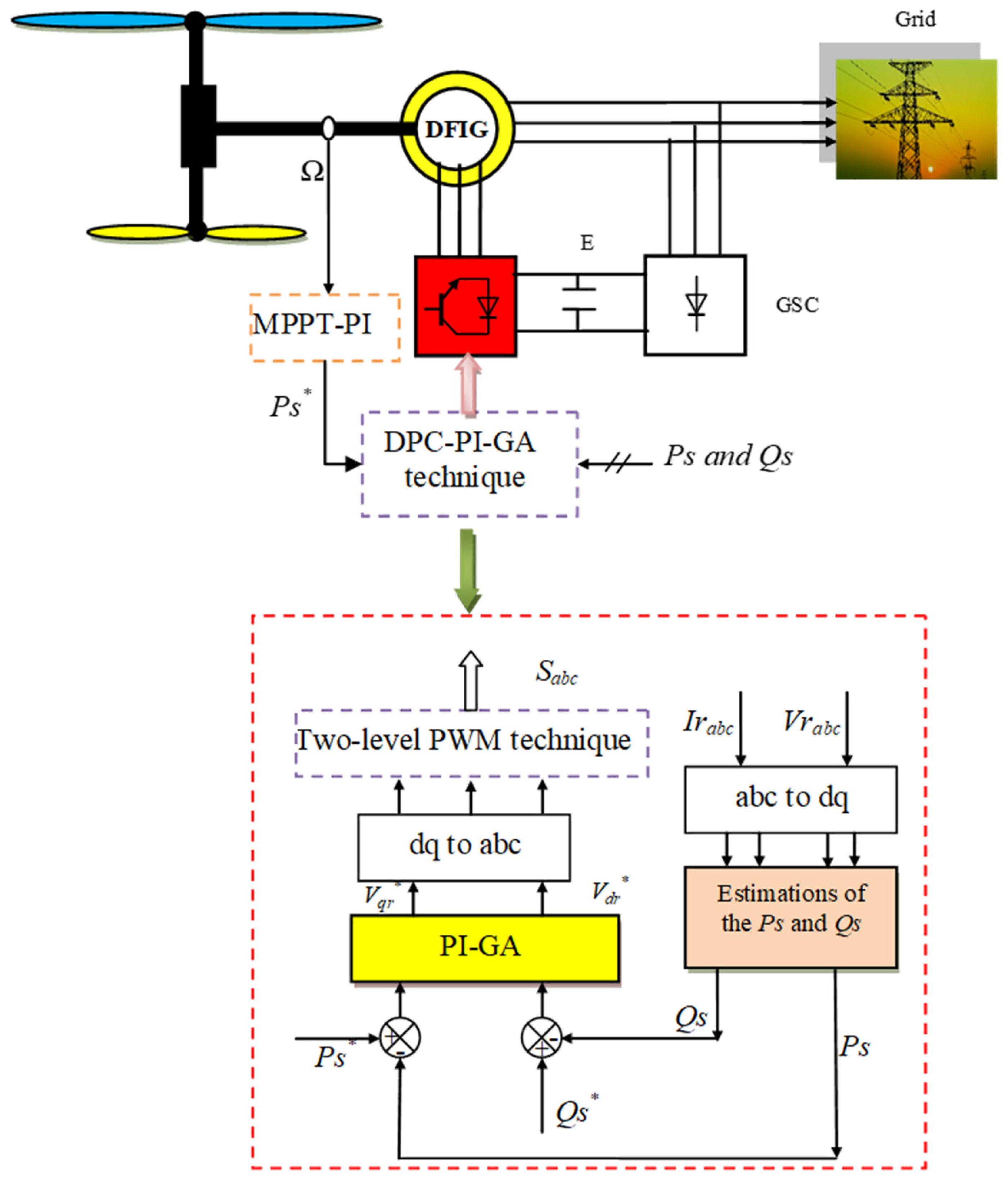
Figure 1 illustrates the DPC-PI approach, which was developed in this study for the purpose of controlling DFIG energies. In this strategy, the PI regulator gain values were calculated using a genetic algorithm (GA). The genetic algorithm implemented an integral-time multiplied-by-absolute error (ITAE) model.
The voltage in the designed approach and the pulses necessary to operate the DFIG inverter are derived using Equation (11).
In this context, Vdr* and Vqr* represent the direct and quadrature rotor voltages, respectively. eQs denotes the Qs error, while ePs signifies the Ps error.
The DPC-PI-GA method is predicated on the estimation of powers, with the flux being estimated first. The estimation of the flux is achieved through the measurement of the current and voltage. The estimation of rotor flux is derived using Equation (12) as outlined in reference [
59].
The voltage is directly proportional to the rotor flux, and its calculation can be performed using Equation (13) as outlined in reference [
60].
In the DPC-PI-GA technique, the stator flux is also estimated. Therefore, the utilization of Equation (14) is imperative for the estimation of both the direct and quadrature stator voltages [
61].
with
.
Equation (15) represents the power estimation used in the DPC-PI-GA technique [
60]. The expressions in this equation are used to calculate the power error.
After demonstrating the DPC-PI-GA technique, which enhances the traditional DPC approach by optimizing PI parameters using a GA, it becomes clear that although this approach improves dynamic performance and robustness compared to classical DPC technology, some limitations still exist, particularly under strong disturbances and parameter changes. To further overcome these shortcomings and achieve higher levels of flexibility, durability, and PQ, the following section presents the enhanced CNC method. Unlike the DPC-PI-GA approach, which relies on the non-connected or semi-connected optimization of fixed controller gains, the CNC strategy incorporates an intelligent control architecture and features high robustness. This transition from an optimized control scheme with fixed parameters to a fully intelligent and adaptive approach provides a natural evolution in control design, enabling improved turbulence rejection, reduced ripple, and enhanced durability. Therefore, the CNC method is presented as an advanced alternative that builds on the strengths of DPC-PI-GA technology while addressing its inherent limitations, delivering superior performance for highly complex and variable WE systems.
4. CNC Method
Cascaded neural control is a sophisticated control strategy that improves the DPC approach of the DFIG. In this framework, the standard DPC structure is expanded by arranging multiple NN-based controllers in a cascaded configuration. Each control layer targets a particular dynamic objective of the DFIG system. The outer neural control loop is typically responsible for regulating Ps and Qs references, while the inner neural loop ensures fast and accurate tracking of these references by generating appropriate rotor voltage commands. By learning the nonlinear relationships between system variables, the cascaded neural controllers effectively compensate for parameter uncertainties, coupling effects, and external disturbances inherent in WE conversion systems. This hierarchical structure has been demonstrated to improve dynamic response, reduce power ripples, and enhance robustness when compared to classical DPC schemes, particularly under variable WSs and grid disturbances. As a result, CNC provides a flexible and adaptive solution for achieving high-performance power regulation in DFIG-based WT systems. Therefore, the advantages of sequential neural control are as follows:
The cascaded structure allows for fast inner-loop control and accurate outer-loop regulation, resulting in better transient response and reduced overshoot in Ps and Qs control.
Neural networks can approximate complex nonlinear dynamics of the DFIG system without requiring an exact mathematical model.
The adaptive learning capability enables the controller to maintain performance despite changes in machine parameters, WS variations, and system uncertainties.
Compared to conventional DPC, the CNC method helps minimize oscillations in electromagnetic torque and power output.
Cascading separates control tasks (e.g., power regulation and voltage generation), simplifying multi-objective control and improving coordination.
Provides better Qs control and improved behavior during grid disturbances such as voltage dips.
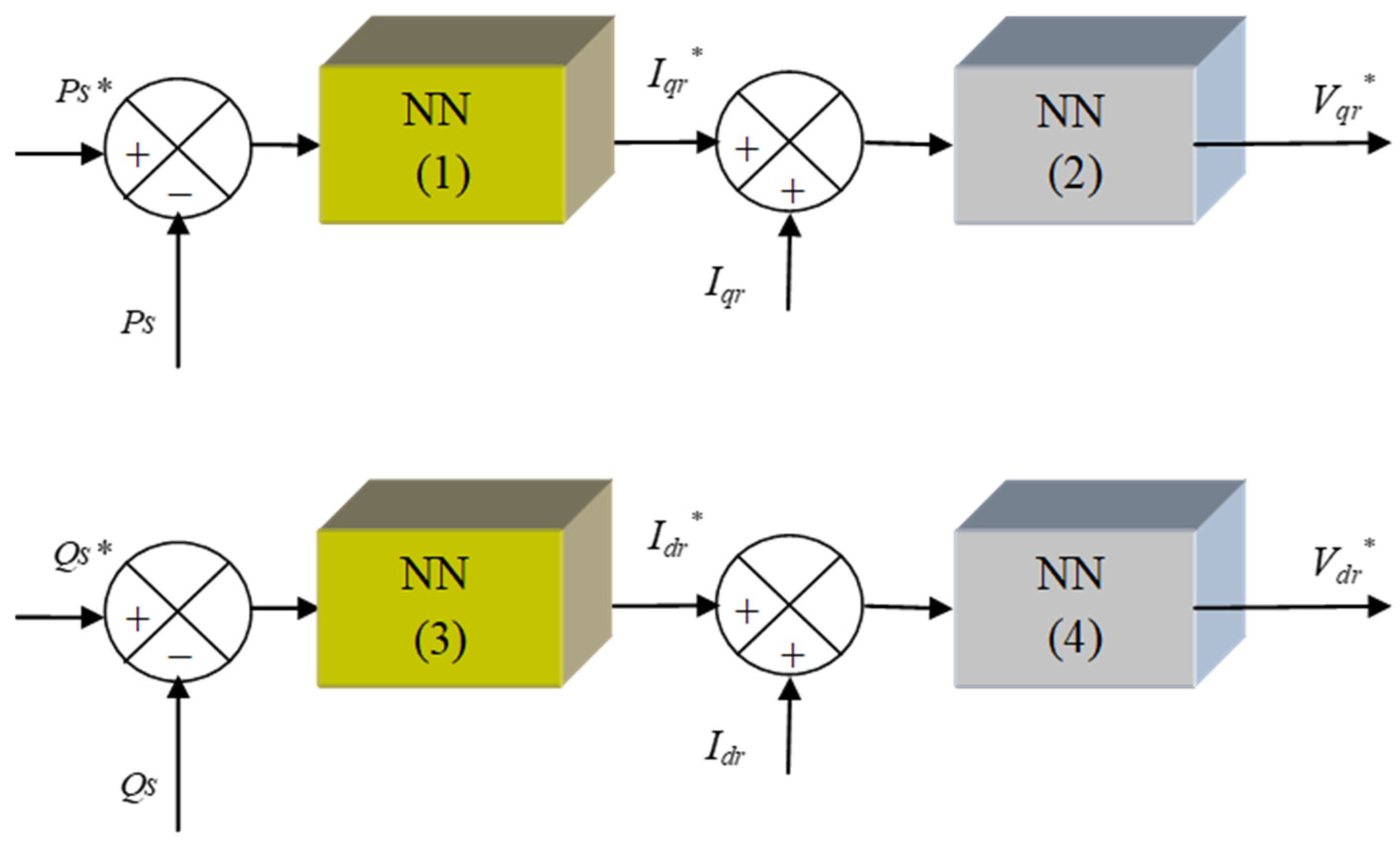
As illustrated in
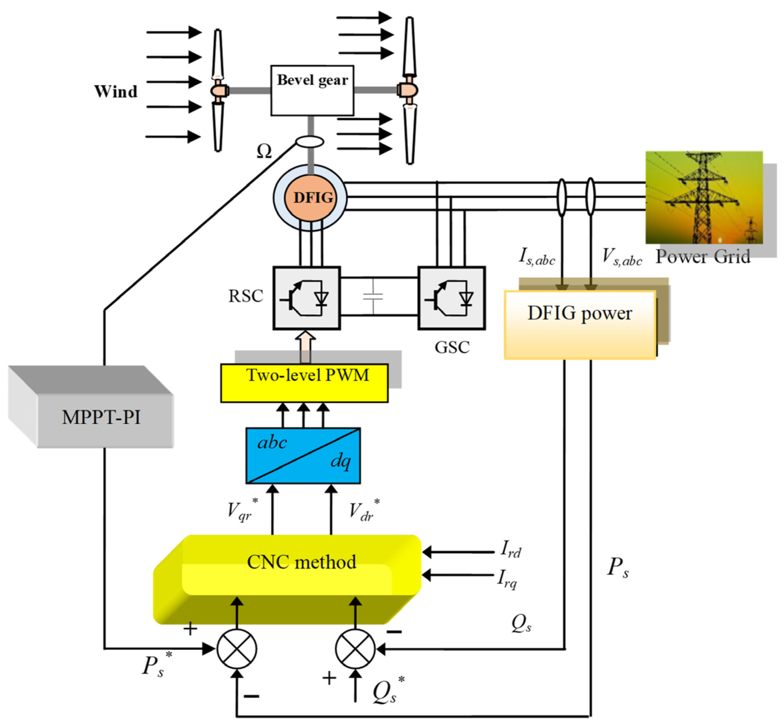
Figure 2, this paper utilizes a CNC strategy to regulate and enhance the power output quality of the DFIG. This strategy exhibits notable distinctions from those reported in the extant literature with respect to operational performance, structural characteristics, robustness, and dynamic response. The implementation of this approach relied on the utilization of neural networks due to their high degree of accuracy, their capacity to effectively reject disturbances, their high degree of robustness, and their ability to enhance dynamic response. To implement the CNC approach, a feedforward backpropagation network was utilized. This particular type of network is implemented in the MATLAB environment through the use of the “newff” function. Furthermore, a gradient descent with momentum and an adaptive learning rate backpropagation algorithm was used to obtain the network structure. The implementation of this algorithm in MATLAB is achieved through the utilization of the “traingdx” function.
The proposed CNC method adds computational complexity due to the real-time evaluation of NN layers at each control step and the presence of four neural controllers. Although CNC requires slightly more time per step, the execution times remain within the limits of modern embedded processors commonly used in wind turbine control, such as ARM Cortex-M or digital signal processor (DSP)-based platforms. This analysis demonstrates that the CNC approach is feasible in realtime, providing a balance between improved control performance and computational requirements suitable for practical WE applications.
The CNC strategy operates in two cascaded neural control layers:
Converts stator power errors into reference rotor currents.
Converts rotor current errors into reference rotor voltages for the converter.
This cascade architecture allows the neural networks to approximate the nonlinear dynamics of the DFIG more effectively while improving power regulation, dynamic response, and converter control performance. Furthermore, this strategy enables the torque current to vary according to WS and Ps. Utilizing MPPT-PI does not increase the complexity of the system under consideration; on the contrary, this strategy is necessary to improve the performance of this system in terms of the energy generated.
As illustrated in
Figure 2, the designed approach relies on calculating the error in both the power and current of the rotating component. This approach does not depend on a mathematical model of the system under consideration, which allows it to yield satisfactory results even if the system parameters change. Furthermore, this approach utilizes NNs, making it more accurate, efficient, and effective in reducing current, power, and torque fluctuations.
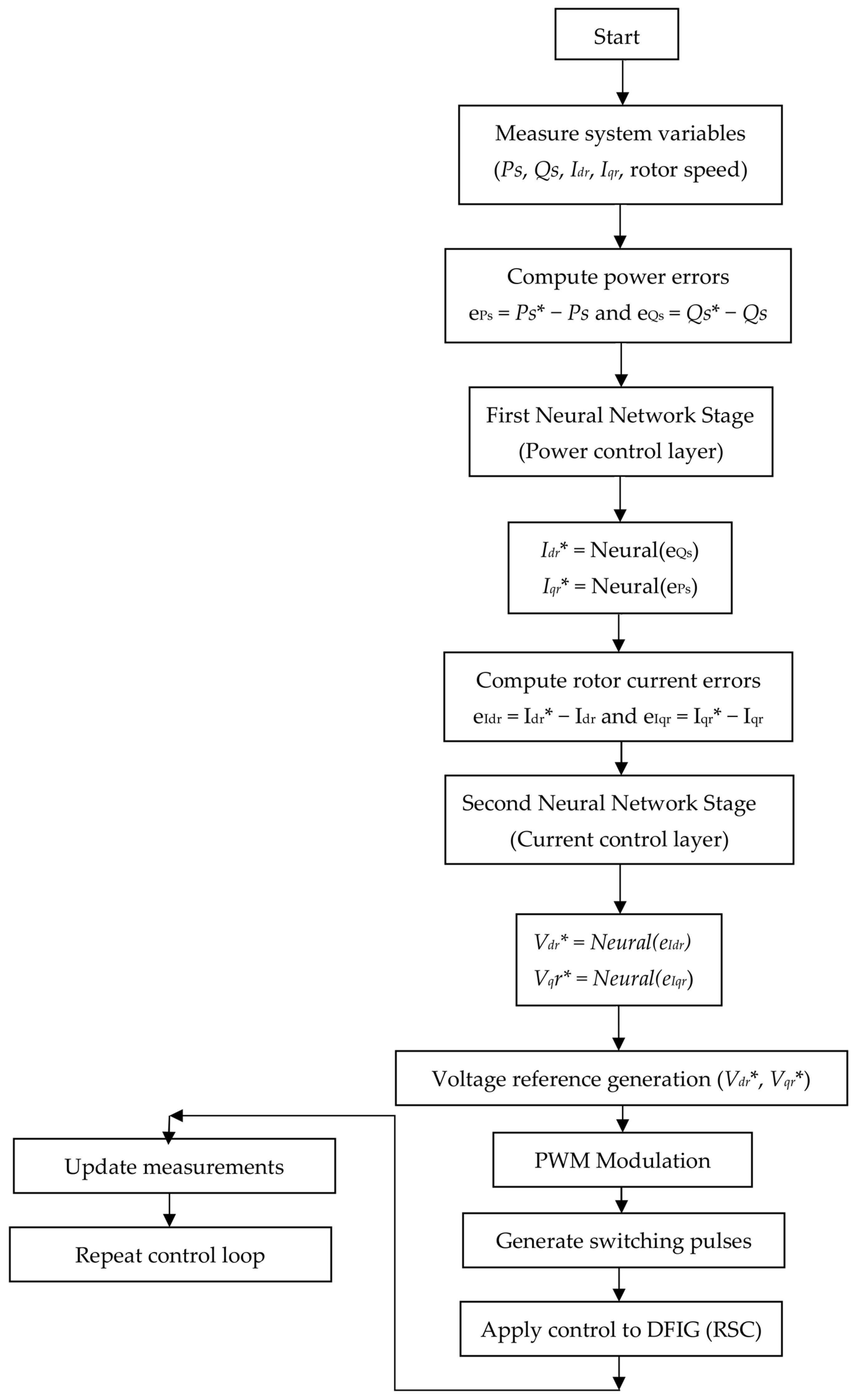
Figure 3 presents a flowchart illustrating and describing the control method using a cascade neural network (CNC) for a DFIG system. This diagram accurately describes how this approach was implemented and applied to the generator. This designed approach was initially applied to the machine inverter only to demonstrate its capability and effectiveness in improving power and current quality without requiring control of the grid inverter. Consequently, the CNC approach is more intricate than the DPC-PI approach. As illustrated in
Figure 4, the first and second loops are employed for the power control. As illustrated in
Figure 4, the CNC approach employs four neural controllers that are characterized by uniformity in terms of the number of internal layers, number of cells, epoch, and function type.
In the designed CNC approach, the reference values for the rotor current are first determined according to Equation (16). According to this equation, the power error is converted to the reference values for the rotor current.
The reference values for the current, determined by Equation (16), are used to determine the error in the rotating current. This error is represented in Equation (17).
The reference voltage values in the designed CNC approach are determined based on the rotor current error (Equation (17)). These reference voltage values are determined according to Equation (18). Therefore, Equation (18) is used to generate the pulses necessary to operate the generator inverter.
To determine the reference value of a direct voltage rotor, two neural network controllers (NN(1) and NN(3)) are used. In the first neural controller (NN(1)), the input is the active power error (), and the output is the reference value of . The second neural controller’s input is also the Idr error and the output is the reference value of .
For the reference value , neural controllers NN (3) and NN (4) are used. The input of neural controller NN (3) is the reactive power error (), while the output is the reference value of . The output of neural controller NN (4) is the reference value of , and the input is the error in the current value Iqr.
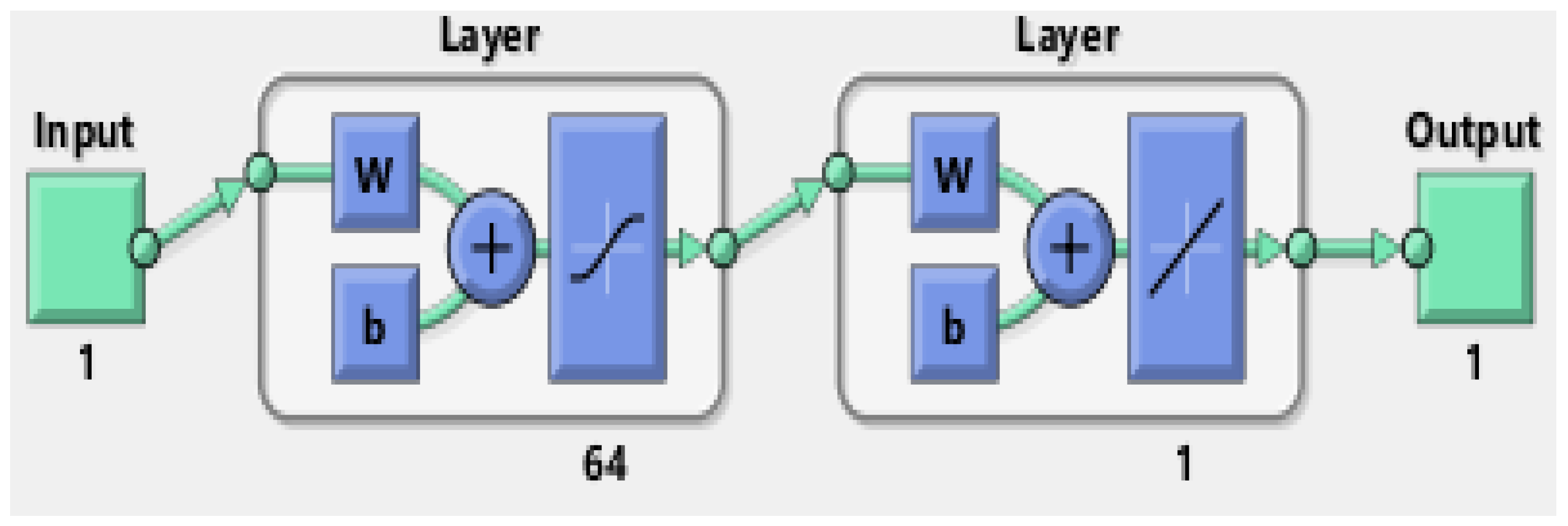
The neural controller was modeled using 64 cells in the first layer and a single cell in the second layer, as illustrated in
Figure 5. In addition, the functions of type ‘
tansig’ and ‘
purelin’ were utilized. The value epoch was set to 1000, the learning rate (lr) to 0.02, and the goal (net.trainParam.goal) to 0. The learning algorithm used in this paper is a Gradient Descending Learning algorithm with Momentum and Adaptive LR. This algorithm is implemented in MATLAB using traingdx. The number of neurons in the first and second layers is 1, while the number of neurons in the Hidden layer is 64. Also, a value of 0.9 was used for the convergence acceleration coefficient. The rendering step value was set to 50 in this work.
Choosing a neural network architecture with a single hidden layer and 64 neurons represents a practical compromise between control performance and computational efficiency. Theoretically, a single hidden layer is sufficient to approximate complex nonlinear couplings while maintaining a relatively simple and stable network architecture for real-time control applications. Increasing the number of layers or neurons may improve approximation capabilities, but it also increases computational load, lengthens execution time, and increases memory usage, potentially impacting real-time performance on embedded control platforms. Conversely, a very small network may reduce computational costs but may limit the controller’s ability to accurately monitor nonlinear dynamics. The 64-neuron configuration provides sufficient learning power to model the system’s nonlinear behavior while maintaining moderate algorithmic complexity. This balance helps ensure rapid convergence, reliable dynamic performance, and practical implementation on the low-cost embedded controllers commonly used in wind turbine power conversion systems.
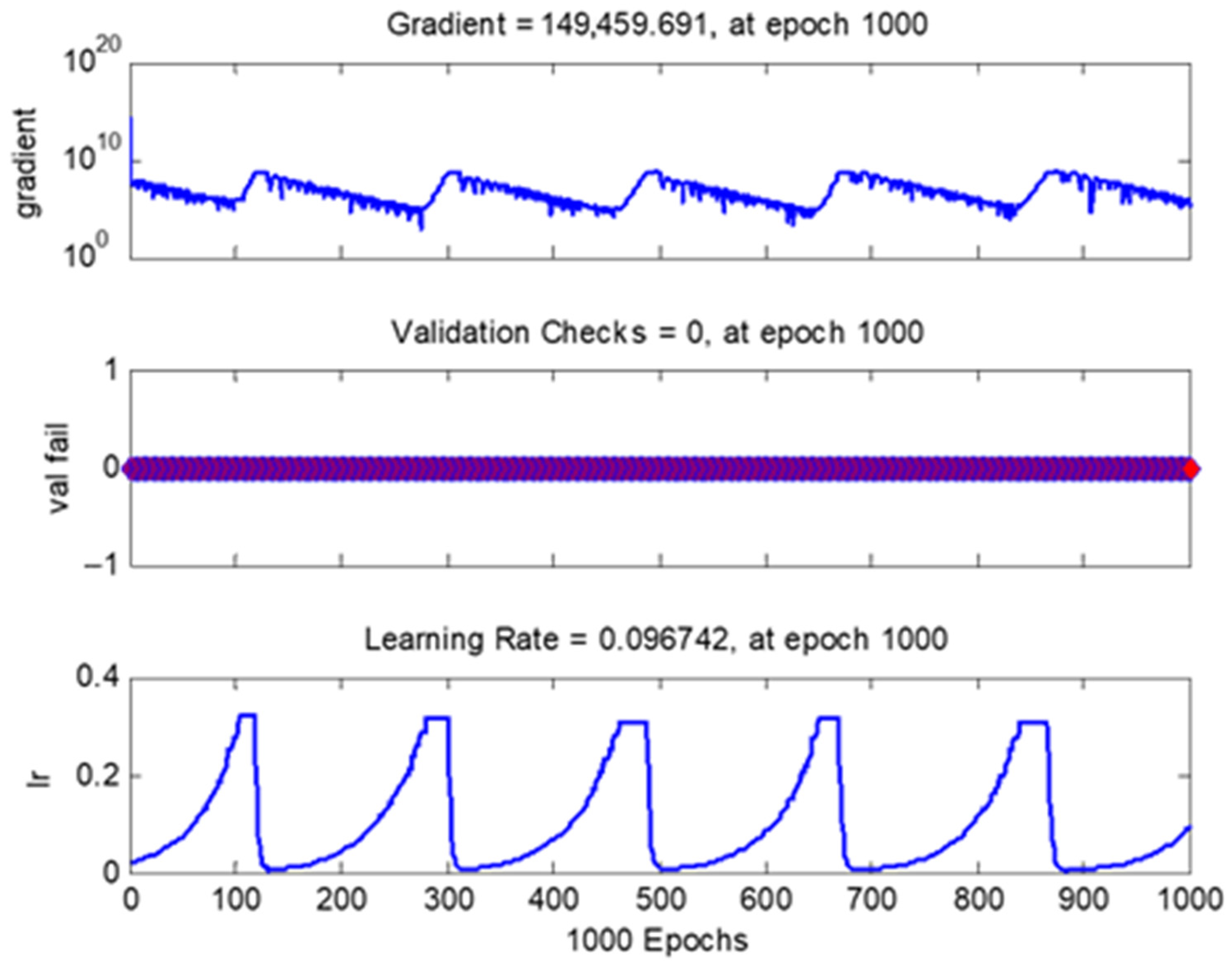
Figure 6 illustrates the features of the neural controller employed to implement the designed approach. This figure represents the learning rate, gradient, and validation error. As illustrated in
Figure 6, the value of val fail is determined to be zero, with minor fluctuations. Also, the value of Gradient is 149,459.691 at a value of 1000 for Epochs.
Figure 6 shows that the value of validation checks is 0 at a value of 1000 for Epochs.
Figure 6 also shows that the learning rate is 0 when Epochs is 1000.
Table 2 summarizes the configuration used for training the neural networks implemented in the proposed control approach. A dataset consisting of 10,000 samples was generated and divided into training, validation, and test subsets with proportions of 70%, 15%, and 15%, respectively. The networks were trained using the backpropagation algorithm for a maximum of 1000 epochs. The optimization process employed a gradient descent method with momentum and adaptive learning rate (GDMALR), with an initial learning rate of 0.02 and a momentum coefficient of 0.9. To enhance convergence and avoid overfitting, early stopping based on the validation loss was adopted as the stopping criterion, while L2 regularization was applied during training. Prior to training, the input data were normalized using Min–Max scaling to improve numerical stability and learning efficiency. The loss function used to evaluate the network performance was the Mean Squared Error (MSE). The training process required a computation time of approximately 41.18 units (seconds), with gradient and performance values reaching 2.29 × 10
14 and 2.08 × 10
16, respectively. In addition, the training computations were accelerated using MEX-based calculations to improve execution efficiency.
The implementation metrics of the proposed neural network-based control system are summarized in
Table 3. The sampling time (
Ts) was set to approximately 1 ms, representing the interval between successive control updates. The runtime per control step, corresponding to the time required for the neural network to compute its output, was measured to be between 0.2 and 0.5 ms, ensuring that the computations are completed well within the sampling period and thus suitable for real-time control. The estimated computational complexity per step is approximately 500–1000 floating-point operations (FLOPs), which is consistent with the small 1-64-1 network architecture employed. The NN consists of a single hidden layer with 64 neurons and one output neurons, and the implementation was tested on standard CPU/DSP hardware using MATLAB simulations. These results indicate that the proposed control approach is computationally efficient and can be executed in real time, satisfying the requirements for fast dynamic response in high-performance DFIG control applications.
The proposed cascade neural network-based power control strategy significantly enhances the sustainability of DFIG wind power conversion systems by improving energy efficiency, operational reliability, and grid compatibility. Unlike conventional DPC method based on PI control, the adaptive neural architecture effectively manages nonlinear dynamics, parameter uncertainties, and wind condition variability, resulting in superior dynamic response and reduced effective power and torque ripples. These improvements reduce mechanical stress on turbine components, thereby extending equipment lifespan and decreasing maintenance frequency and material consumption. Furthermore, enhanced Qs regulation promotes grid stability and facilitates increased reliance on renewable energy sources. By improving energy extraction and ensuring stable operation under varying environmental conditions, the proposed CNC approach contributes to lower lifecycle costs, reduced environmental impact, and increased resilience of WE systems—key pillars for sustainable energy development and long-term decarbonization strategies.
5. Stability Study
This section examines the stability of the designed approach and the DPC-PI-GA approach using the Bode curve. The Bode curve method is a prominent strategy for proving stability. This method is straightforward and does not require complex calculations, as MATLAB is used for this purpose. The Bode curve method is a graphical approach that relies on extracting curves for both phase and magnitude (dB).
This paper employs the linear analysis points method to extract the Bode curve. This method is a control design unit used to identify a point in the control system model as a critical point for linear analysis and controller adjustment.
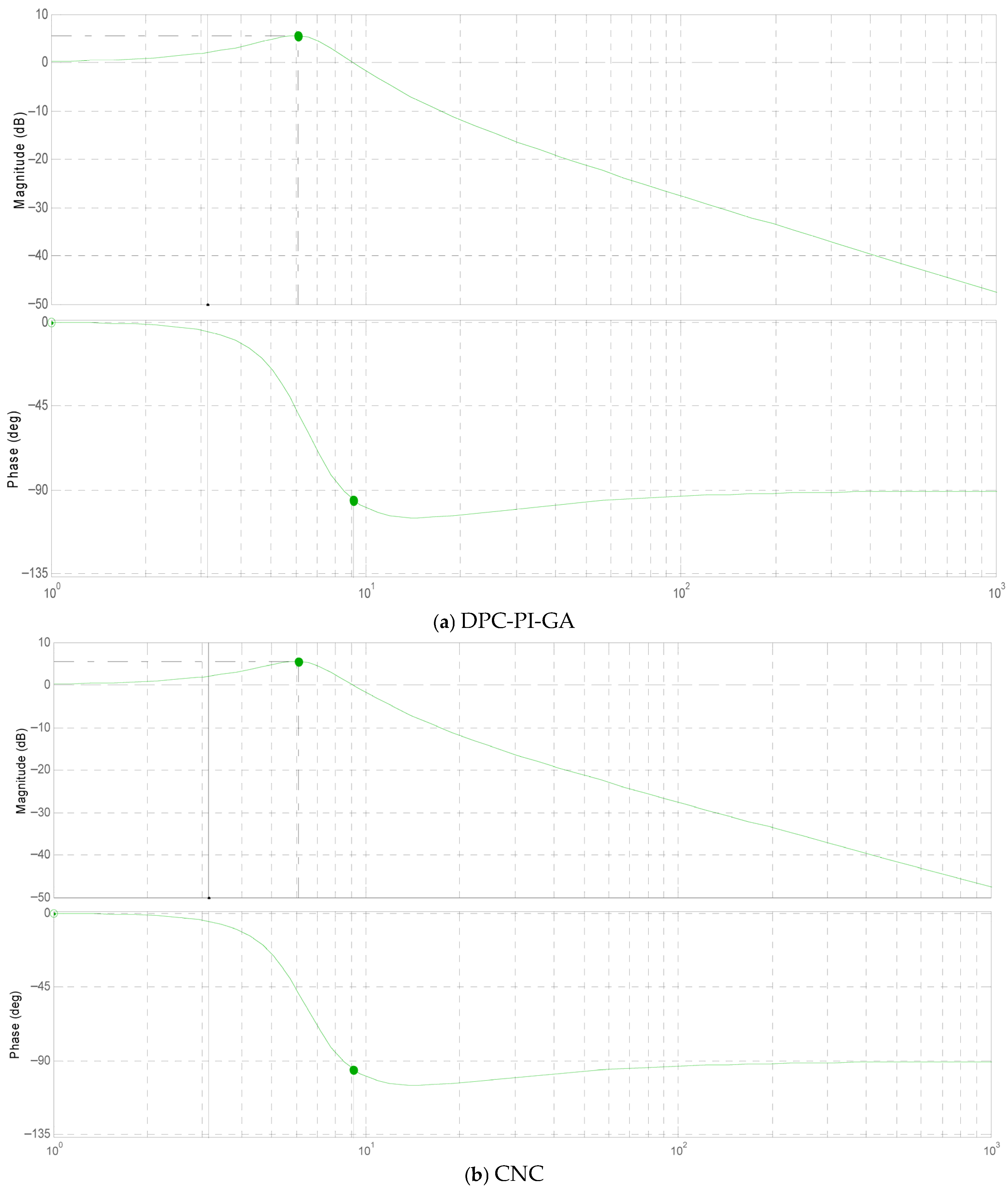
Figure 7 represents the Bode curve using linear analysis points method for the two approaches. From
Figure 7a, it is observed that the values of both phase and Magnitude (dB) for the DPC-PI-GA approach change with frequency and take on negative values. The phase value varies from 0 to −135 degrees, while the Magnitude (dB) value varies from 5.53 to −50 dB. Based on this figure, the Peak gain (dB) value for the conventional approach was 5.53 at a frequency of 6.1 rad/s. On the other hand, at a frequency of 8.97 rad/s, the Magnitude (dB) value was 0.328 dB. In the case of the DPC-PI method, the Phase margin (deg) value was estimated at 84.8, while the Dely Margin (sec) value was estimated at 0.162 s at a frequency of 9.13 rad/s. Since the phase margin value is positive (84.8 deg), the DPC-PI approach is stable.
Figure 7b represents the phase and magnitude (dB) curves of the designed approach. From this figure, we can see that both phase and magnitude (dB) are negative and change with frequency. The phase value when the Magnitude (dB) is zero is approximately −95.2 degrees. Therefore, the phase margin is 84.8 degrees. On the other hand, the Peak gain (dB) value using the designed approach is 5.53 dB when the frequency is 6.1 rad/s. If the frequency is 9.13 rad/s, the Magnitude (dB) value is −0.00746 dB. Therefore, the most prominent results according to the Bode curve are as follows:
Phase margin (deg) = 8.84.
Dely margin (sec) = 0.162.
At frequency (red/s) = 9.13.
Closed loop stable? Yes.
In the case of the designed approach, the Phase margin value is positive, and therefore, this approach is stable.
6. Comparison with DPC-PI
Recent research on advanced control strategies for DFIG-based WE systems has increasingly focused on intelligent and adaptive approaches to overcome the limitations of classical controllers. Among these, the CNC approach has emerged as a promising alternative to the classical DPC method with PI regulators (DPC-PI). In the cascaded neural scheme, multiple NN-based controllers are arranged in a hierarchical structure: an outer loop adjusts high-level power references (Ps and Qs), and an inner loop generates precise voltage or current controls to achieve those references. This structure contrasts with DPC-PI, where fixed PI controllers directly modulate inverter switching to regulate stator power and rotor currents.
Compared to DPC-PI, the CNC method shows several notable improvements. The learning capabilities of NNs allow the controller to approximate the nonlinear dynamics of the DFIG system more effectively, especially under parameter uncertainties and rapidly changing wind conditions. These results in reduced power and torque ripples, faster dynamic response, and better disturbance rejection than the PI-based DPC, which often requires extensive retuning and still suffers from limited robustness. Moreover, the cascaded architecture facilitates decoupled handling of multiple objectives (e.g., torque regulation versus Qs support), whereas DPC-PI typically struggles to balance these within a single control loop without performance trade-offs.
However, the cascaded neural method is not without challenges. Its increased computational demand and reliance on quality training data make real-time implementation more complex than the relatively simple and well-understood DPC-PI approach. Additionally, guaranteeing closed-loop stability analytically remains more difficult, as neural controllers behave as adaptive “black boxes” rather than controllers with explicitly defined transfer functions.
7. Results
In this section, the designed approach is verified using MATLAB under various operating conditions. The DPC-PI-GA approach is utilized for the purpose of comparison. The necessary graphical and numerical results are extracted to demonstrate the effectiveness and robustness of the designed CNC approach. To model the designed power system, a 1.5 MW DFIG MRWT is employed. The DFIG parameters used in this work are 50 Hz,
fr = 0.0024 N.m/s, 1500 kW,
Lm = 13.5 mH,
p = 2,
Rs = 12 mΩ,
Rr = 21 mΩ,
Lr = 13.6 mH,
J = 1000 kg.m
2, 380/690 V, and
Ls = 13.7 mH [
40,
42].
7.1. Test with MPPT Technique
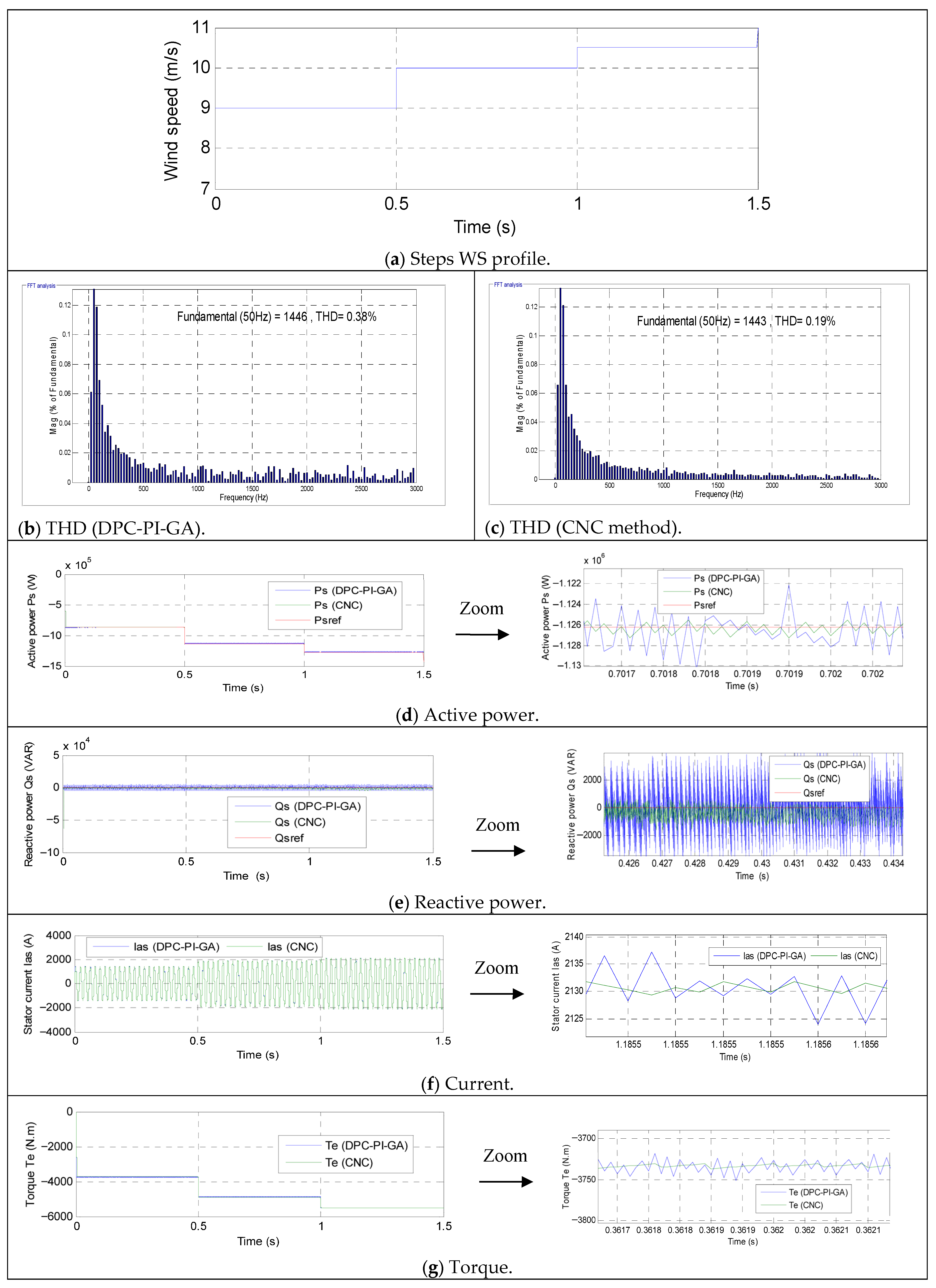
The performance of the proposed CNC approach was evaluated under an MPPT operating condition to assess its effectiveness in extracting optimal WE. During the course of this experiment, the WS was modified as indicated in
Figure 8a. The MPPT algorithm generated the reference effective power corresponding to the optimal blade tip speed ratio, which was then tracked by the DPC sequential neural controller. The MPPT algorithm generated the reference
Ps corresponding to the optimal tip speed ratio, which was then tracked by the cascaded neural DPC controller. The findings indicate that the DFIG system demonstrated a high degree of success in following the MPPT reference with a high degree of accuracy, thereby ensuring maximum energy capture from the wind. The graphical outcomes of this evaluation are presented in
Figure 7, while the numerical outcomes are displayed in
Table 4 and
Table 5.
Figure 8b,c illustrate the THD of the current under both control conditions. According to the aforementioned figures, the THD value was 0.38% lower under the conventional approach and 0.19% lowers under the designed CNC approach. These values indicate that the designed approach reduced the THD value by approximately 50% compared to the DPC-PI-GA approach. However, the designed approach yielded an unsatisfactory value in this test for the amplitude value of the fundamental (50 Hz) signal compared to the DPC-PI-GA. The value of this amplitude was estimated at 1446 A using the DPC-PI-GA method and 1443 A using the designed approach. Consequently, it can be posited that the amplitude value in this test constitutes a disadvantage of the designed approach. This disadvantage can be attributed to the values of the neurons in each layer. This disadvantage can be overcome in the future by employing alternative intelligent strategies integrated with NNs.
Figure 8d shows the change in
Ps of the two controllers during the first test. According to this figure, the
Ps follows the reference value well with a fast dynamic response. Also, some ripple is observed in this power level. Compared to traditional control, sequential neural control resulted in less
Ps ripple, a faster approach to the maximum power point, and a reduction in SSE. Furthermore, the adaptive nature of neural controllers enabled smooth transitions during changes in WS.
Figure 8e illustrates the variation in
Qs of the two controllers during normal operation. As demonstrated in this figure, the power remains constant irrespective of variations in WS. This power output is observed to remain at zero regardless of WS. Additionally, sudden changes in WS do not affect this power output for either control. Conversely, fluctuations in power output are observed, with the magnitude of these fluctuations being significantly greater when employing the DPC-PI-GA approach compared to the designed approach.
Figure 8f illustrates the variation in current for the two controllers during the initial test. In this test, the current exhibits a reciprocal relationship with WS, decreasing as WS increases and increasing as WS decreases. Additionally, the current exhibited by the two controllers follows a sinusoidal pattern with a period of 0.02 s. As illustrated in
Figure 8f, the designed approach yielded a reduced number of ripples in comparison to the traditional approach, thereby substantiating its reliability and efficacy as a control option. In this initial trial, the current ripple was estimated at 8 amps using the conventional method and 2.2 amps using the designed method. Consequently, the designed method demonstrated a 72.50% reduction in current ripple compared to the conventional method.
The torque change for the two controllers is represented in
Figure 8g. The torque change exhibits a similar pattern to the
Ps change, demonstrating a rapid dynamic response in both controllers. As illustrated in
Figure 8g, the torque for both controllers assumes negative values, thereby indicating that the system under investigation is power generating. The torque ripples in this test were estimated at 30 N.m and 5.84 N.m for the DPC-PI-GA and CNC methods, respectively. In consideration of the aforementioned values, it can be determined that the designed approach is more efficacious in reducing torque ripples in comparison to the DPC-PI-GA approach. Consequently, the designed approach led to an estimated 80.53% reduction in these ripples, suggesting its potential as a promising solution.
The simulation results unequivocally demonstrate that the proposed CNC strategy exhibits a marked superiority over the conventional DPC-PI approach in controlling the DFIG-based WE conversion system. In the context of variable WS and grid conditions, the CNC method demonstrates a faster dynamic response with reduced rise and settling times. This enhancement can be attributed to the learning and nonlinear approximation capabilities of the NNs in both the outer power loop and the inner control loop. Conversely, the DPC-PI demonstrates a more gradual convergence trajectory and exhibits discernible performance deterioration in the presence of parameter variations.
In terms of PQ, the proposed strategy achieves lower Ps and Qs ripples and a substantial reduction in current THD compared with DPC-PI, reflecting smoother control action and better tracking accuracy. The NN controller also exhibits enhanced robustness against disturbances and uncertainties, with negligible SSE and reduced overshoot. Even though the CNC method engenders greater computational intricacy in comparison with DPC-PI, the enhanced performance in dynamic behavior, robustness, and PQ validates its implementation for high-performance DFIG applications.
As illustrated in
Table 4, the CNC technique consistently demonstrates superior performance in terms of harmonic performance when compared to the DPC-PI-GA technique across all WSs. This is achieved while maintaining signal amplitude that is essentially equivalent to that of the fundamental signal. Specifically, the THD achieved with CNC is reduced by about 50% at 9 m/s, 41.93% at 10 m/s, and 34.48% at 10.50 m/s compared with DPC-PI-GA, indicating a clear improvement in signal quality and a more effective suppression of harmonics as WS increases. Although the relative reduction in THD slightly decreases at higher WSs, CNC still maintains THD values around 0.18–0.19%, which are significantly lower than those of DPC-PI-GA. In contrast, the amplitude of the fundamental 50 Hz component remains nearly identical for both controllers, with differences below ±0.07%, demonstrating that the harmonic reduction achieved by CNC does not come at the expense of fundamental signal magnitude. Overall, these results suggest that CNC provides a substantial enhancement in PQ while preserving the desired fundamental performance under varying wind conditions.
As illustrated in
Table 5, the proposed CNC method demonstrates a clear advantage over the DPC-PI-GA strategy. For
Qs, CNC reduces the overshoot from 2705 VAR to 516 VAR, corresponding to an improvement of 80.9%, while the
Ps overshoot is drastically reduced by 98.3%, indicating excellent transient damping. Power ripples are also significantly mitigated, with reductions of 76.1% for
Qs and 85.3% for
Ps, reflecting smoother steady-state behavior and improved PQ. Moreover, the SSE is decreased by 75.5% for
Qs and 78.6% for
Ps, confirming higher tracking accuracy. Although CNC achieves a much faster response for
Qs (78.1% improvement), a slight degradation is observed in
Ps response time (–23.3%), which can be attributed to the additional computational processing of the NNs. Overall, the results demonstrate that CNC provides substantial gains in robustness, accuracy, and PQ compared to the DPC-PI-GA approach.
7.2. Robustness Test
The robustness of the proposed CNC strategy was assessed by subjecting the DFIG-based WE conversion system to parameter variations and external disturbances. Key machine parameters, including stator and rotor resistances, were deliberately modified from their nominal values, and sudden WS variations were introduced to assess the controller’s capacity to maintain stable operation. The results of this test are displayed in
Figure 9, while the numerical results are enumerated in
Table 6.
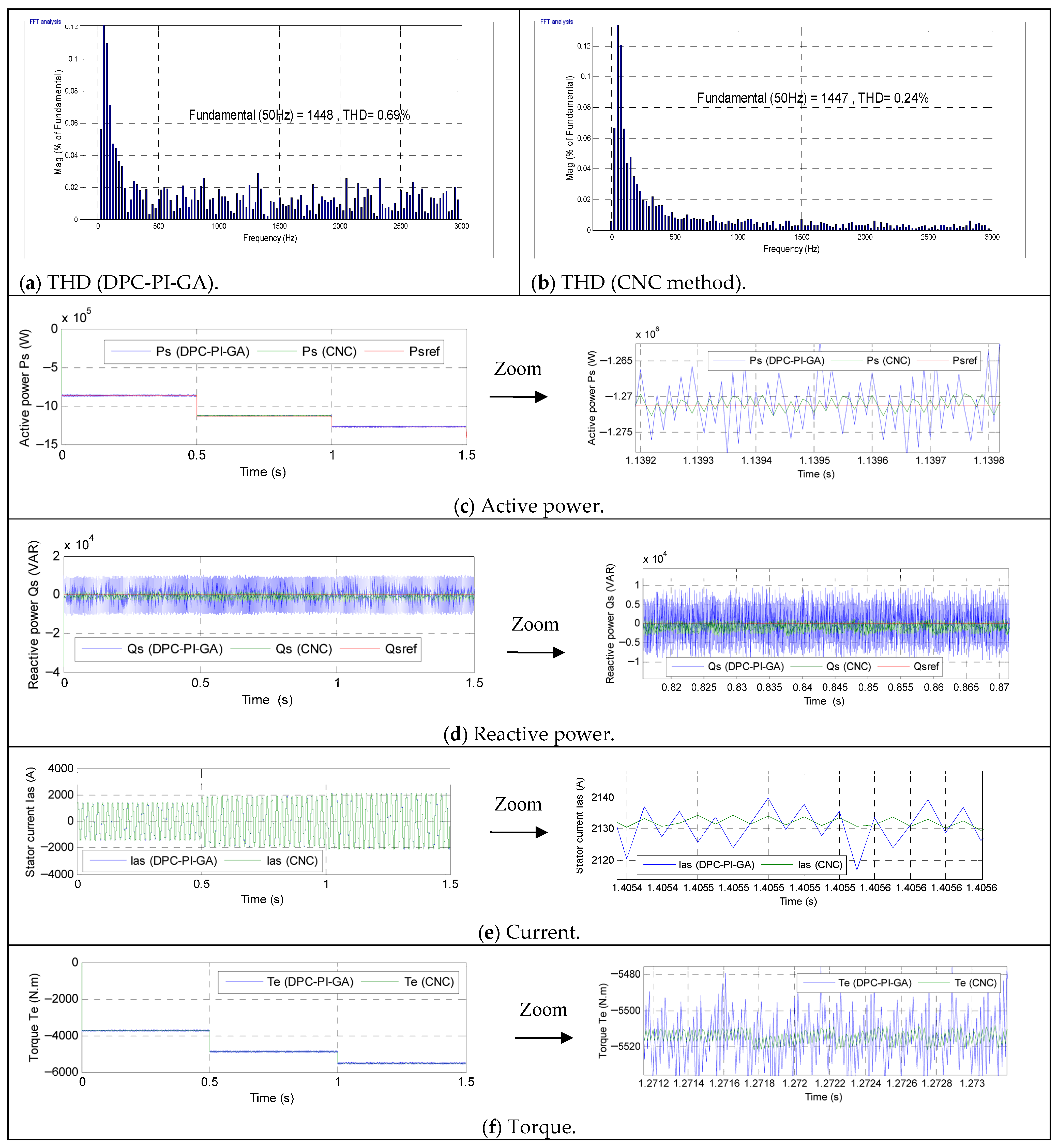
Figure 9a,b illustrate the THD of the current for the two controllers when the system parameters undergo alteration. The value was estimated at 0.69% using the DPC-PI-GA approach and 0.24% using the designed CNC method. Consequently, the THD value exhibited a substantial sensitivity to alterations in the machine parameters, with this effect being most evident in the DPC-PI-GA technique. In this experiment, the CNC technique that was meticulously designed exhibited a 65.21% reduction in THD value when compared to the DPC-PI-GA approach. As illustrated in
Figure 9a,b, the DPC-PI approach demonstrates superiority in amplitude over the designed approach. The amplitude was measured at 1447 A when the designed approach was employed and 1448 A when the conventional approach was used. Consequently, the amplitude can also be regarded as negative for the designed approach in this test. This shortcoming can be ascribed to the inherent properties of NNs. As is widely recognized, NNs are heavily dependent on experience, which necessitates a considerable time investment to enhance outcomes. In the future, this drawback may be overcome by employing alternative strategies, such as integration, which has the potential to markedly enhance operational performance.
The results shown in
Figure 9c,d demonstrate that the CNC scheme maintains precise regulation of
Ps and
Qs despite changes in the system parameters. It is noteworthy that parameter changes do not affect the reference tracking of energies; the energies of both controllers continue to track the energies effectively with a rapid dynamic response. In contrast to the conventional DPC-PI approach, which exhibits noticeable performance degradation and increased power oscillations under similar conditions, the neural-based controller maintains smooth dynamic behavior with minimal overshoot and reduced ripples. The adaptive learning capability of the CNC method enables effective compensation for modeling inaccuracies and disturbances, ensuring consistent performance without the need for retuning. These findings confirm the strong robustness of the proposed control approach and its suitability for reliable operation of DFIG systems in realistic and uncertain wind and grid environments.
Figure 9e illustrates the current variation of the two controllers during the durability test. Notwithstanding the modification of the instrument parameters, the current continues to vary with WS, consistent with the results of the initial test. Additionally, the current exhibits a sinusoidal pattern with a period of 0.02 s for both controllers. In this test, the current ripple values were 20 A and 2.50 A for the DPC-PI-GA and CNC approaches, respectively. These values indicate that the current ripple is significantly lower when using the designed CNC approach compared to the DPC-PI-GA approach. This reduction is estimated at 87.50% compared to the DPC-PI-GA method. This percentage is indicative of the high effectiveness of the designed approach in improving current quality despite changes in system parameters. Consequently, this outcome renders this approach a subject of interest for future industrial applications.
Figure 9f illustrates the torque variation of the two controllers during the durability test. This figure demonstrates that, despite alterations in the system parameters, the torque of the controllers persists in reflecting changes in WS. Additionally, the torque values of the controllers are negative, indicating that the system continues to transmit power to the grid despite the parameter changes. The alteration of machine parameters has been demonstrated to influence torque, thereby resulting in augmented torque ripple in comparison to the initial test. Torque ripple in the test was 70 N.m for the designed CNC technique and 14 N.m for the DPC-PI-GA approach. Consequently, the CNC approach that was meticulously designed reduced torque ripple by approximately 80%. This percentage is indicative of the high performance and robustness of this designed approach despite system parameter changes, thereby making it a superior choice for control applications.
Table 6 highlights the comparative performance of the DPC-PI-GA and CNC methods in Test 2, with the reported ratios clearly illustrating the reduction rates achieved by CNC across most criteria. For overshoot, CNC achieves a substantial reduction of 41.82% in
Qs and 62.50% in
Ps, indicating a significantly smoother transient response, particularly for
Ps. Even more pronounced improvements are observed in ripple reduction, where CNC decreases ripples by 76.79% for
Qs and 80.22% for
Ps, reflecting a marked enhancement in steady-state signal quality and stability. Similarly, the SSE is considerably reduced, with CNC providing reductions of 62.50% for
Qs and 77.77% for
Ps, confirming its superior accuracy in tracking reference values. However, these gains come at the cost of slower dynamics, as the response time increases significantly, by about 98.07% for
Qs and 72.29% for
Ps, compared with DPC-PI-GA. Overall, the results suggest that CNC prioritizes robustness, accuracy, and signal smoothness, making it highly effective for reducing overshoot, ripples, and SSEs, albeit with a trade-off in transient speed.
7.3. Test with Constant Wind Speed
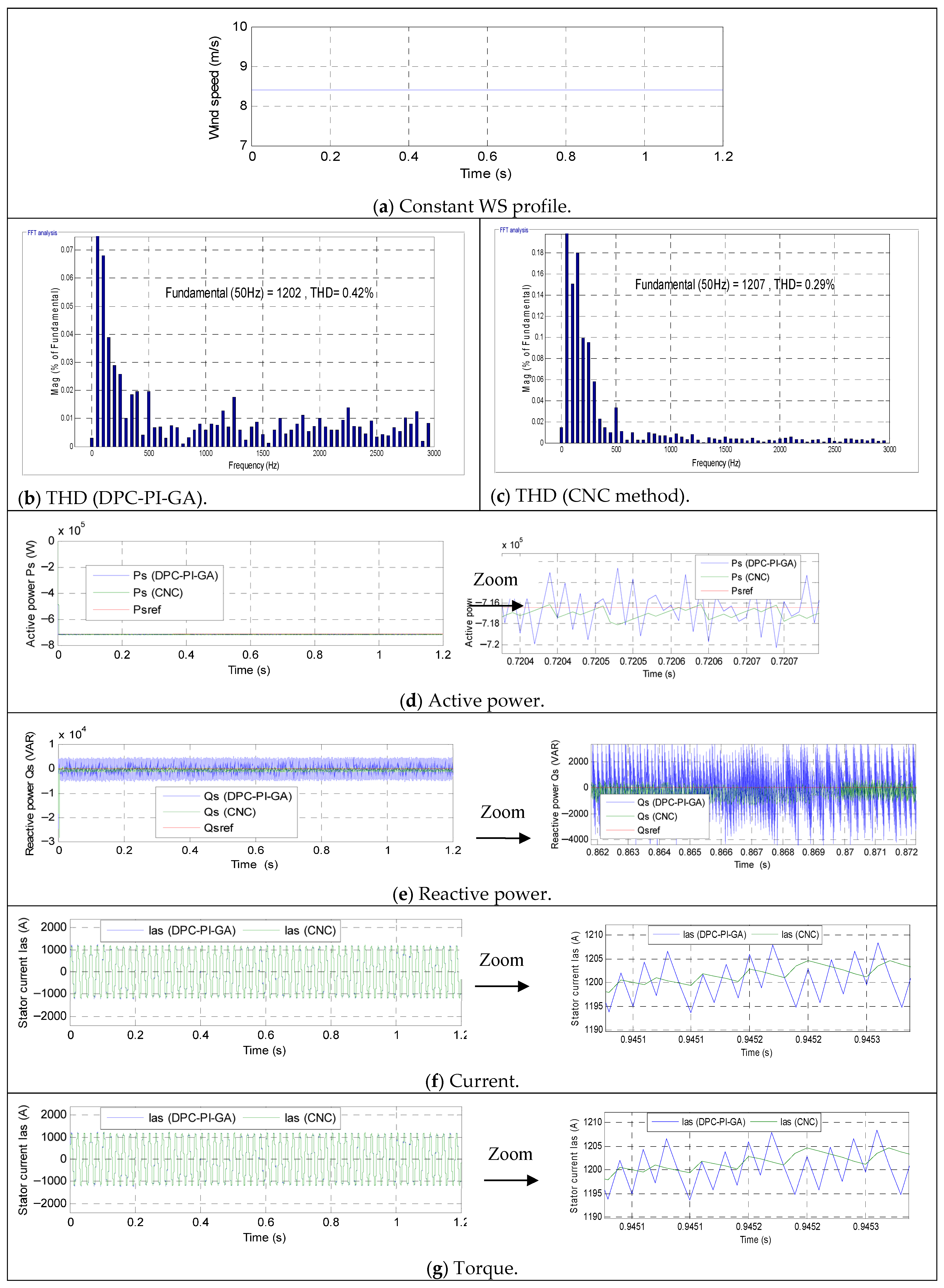
This test investigates the effectiveness of the designed approach in improving the performance of the studied energy system under a constant, low WS (8.5 m/s). The WS variation model used in this test is shown in
Figure 10a. The results obtained are also shown in
Figure 10, while the numerical results and reduction percentages are listed in
Table 7.
Figure 10b,c represent the THD value of the current during the third test of the two controls. These figures show that the THD value was 0.42 using the DPC-PI method, while it was 0.29 using the designed CNC approach. Therefore, the designed CNC method significantly reduced the THD value in this test compared to the DPC-PI strategy. This reduction highlights the superiority of the designed approach under conditions of relatively low and constant WS. This reduction was 30.95% compared to the DPC-PI approach.
Figure 10d,e represent the variation in both
Ps and
Qs in the third test. These figures demonstrate that the power outputs remain consistent with the reference values even when the WS is constant. Furthermore, the
Qs is set to 0 VAR to ensure a power factor of 1. The
Ps output is 716 kW when the wind speed is 8.4 m/s. These figures show fluctuations in these power outputs. These fluctuations are significantly lower when using the designed approach compared to the DPC-PI approach, demonstrating the effectiveness of the designed approach in improving PQ even at a constant WS.
Figure 10f represents the current change of the two controllers during the third test. This figure shows that the current change pattern continues to follow the WS pattern, exhibiting ripples. The current also maintains a sinusoidal pattern with a frequency of 0.02 s. It is observed that the maximum current value at a WS of 8.4 m/s reached 1200 A. Furthermore, the current ripples were 13.25 A and 2.50 A for the conventional and designed approaches, respectively. The designed approach reduced the current ripples by 81.13% compared to the DPC-PI technique. This percentage demonstrates the effectiveness of the designed CNC technique in improving current quality at constant WSds, making it a reliable solution for other industrial applications such as photovoltaic system control.
Figure 10g represents the torque change under a constant WS. This torque takes a negative value, indicating that the system is generating power. Conversely, the torque remains constant in the presence of ripples. These ripples were measured at 37.41 N.m and 5.64 N.m for the conventional and designed approaches, respectively. These values indicate that the ripples are significantly lower (84.92%) when using the designed approach. This percentage confirms the effectiveness of the designed CNC strategy in improving the characteristics of the studied energy system, making it a highly significant solution.
Table 7 represents the numerical results and reduction percentages obtained in the third test for the two approaches.
Table 7 highlights a clear performance contrast between DPC-PI-GA and CNC in Test 3, reflecting the different dynamic behaviors imposed by each control strategy. For
Qs, CNC produces a much higher overshoot (516.40 VAR) compared to DPC-PI-GA (111.20 VAR), corresponding to a −78.46% ratio, which indicates that DPC-PI-GA significantly damps the transient energy injected into the system. Physically, this reduction can be attributed to the optimized PI gains tuned by the GA, which better balance the electromagnetic energy exchange between the converter and the grid, thereby limiting excessive current excursions. Similarly, the ripple magnitude in
Qs decreases from 10,000 VAR to 2000 VAR (80% reduction), suggesting improved switching state selection and smoother voltage vector application, which reduce high-frequency oscillations in the instantaneous power. The response time for
Qs improves from 1.33 ms to 0.35 ms (73.68% reduction), indicating faster dynamic tracking due to more aggressive and precise control action.
For Ps, CNC reduces overshoot by 24.74% (from 2990 W to 2250 W), which implies better transient containment of active current components and reduced DC-link stress. Ripple reduction reaches 71.62%, reflecting enhanced steady-state stability and lower harmonic distortion in the output current. However, the response time increases significantly (from 1.35 ms to 4.40 ms, −69.31%), revealing a trade-off between stability and speed; the controller likely prioritizes smoothing and robustness over rapid convergence. Finally, the SSE is substantially reduced for both Qs (72.03%) and Ps (85%), confirming that CNC achieves more accurate long-term power regulation. Physically, this indicates improved decoupling between Ps and Qs channels and more precise compensation of parameter uncertainties, resulting in reduced residual tracking error and enhanced overall PQ.
The reported THD values for the three tests—0.19% (Test 1), 0.24% (Test 2), and 0.29% (Test 3)—are well below the limits specified by widely recognized power quality standards, including IEEE 519 [
62] and IEC 61000-3-6 [
63], which generally set the maximum allowable voltage THD at 5% for low- and medium-voltage systems. This indicates that, in addition to providing significant relative improvements compared to the DPC-PI-GA controller, the proposed CNC strategy also ensures absolute compliance with standard grid harmonic requirements.
The significant reductions in THD and current/torque ripple achieved by the proposed CNC strategy have important practical implications for grid-connected power transformers. The reduction in THD contributes to better compliance with international grid standards (such as IEEE 519 and IEC 61000-3-6), thus reducing the risk of fines and improving overall PQ. Furthermore, the reduction in ripple minimizes switching and connection losses, improving energy efficiency and reducing thermal stress on power electronics components. These combined effects contribute to extended transformer lifespan, increased operational reliability, and reduced maintenance requirements, highlighting the tangible engineering benefits of the proposed control strategy, which extend beyond numerical performance improvements.
8. Disadvantages of Cascaded Neural Control
Based on the results obtained in
Section 7 and compared to those achieved in
Section 5, the designed approach has drawbacks. These limitations can be addressed in subsequent research endeavors. These drawbacks can be primarily attributed to the choice of NN characteristics. It is widely acknowledged that NNs are profoundly dependent on experience.
The following drawbacks were identified in this work:
Multiple neural controllers require higher processing power, which can challenge real-time implementation.
Neural networks need proper training, and poor initialization or tuning may lead to slow convergence or suboptimal performance.
Guaranteeing closed-loop stability is more complex compared to classical control methods and often requires additional analytical tools.
The efficacy of a performance-based system is contingent upon the quality and representativeness of the training dataset.
Advanced hardware and software platforms may be required, increasing system cost.
Neural controllers operate as “black-box” models, making system behavior harder to interpret and analyze.
Table 8 represents a study of the variance in specific quantities in the three tests of controls designed in this paper. The results presented in
Table 8 clearly highlight the differences in performance between the DPC-PI-GA controller and the CNC method. The CNC strategy demonstrates superior steady-state performance by significantly reducing current harmonic distortion and current ripples, with average values of 0.24% and 2.40 A, respectively, compared to 0.50% and 13.75 A obtained with the DPC-PI-GA controller. This improvement indicates a more accurate regulation of the current waveform and better PQ. In addition, the
Ps ripple is drastically reduced when using the CNC approach, with an average value of 2290 W, whereas the DPC-PI-GA controller exhibits a much higher fluctuation level reaching an average of 11,066.67 W. The lower standard deviation values obtained with the CNC method also confirm the higher stability and consistency of its performance across the three tests. However, despite these advantages, the DPC-PI-GA controller provides a faster transient response, achieving an average response time of 1.28 ms compared to 4.32 ms for the CNC method. Therefore, while CNC offers significant improvements in steady-state behavior and PQ, the DPC-PI-GA controller remains advantageous in applications requiring rapid dynamic response.
As illustrated in
Table 9, a comparative analysis is presented between the proposed CNC method and other related works with regard to the THD value of current. The proposed CNC method was compared with several strategies found in the literature, such as Integral SMC, Antcolony optimization-based DTC, and sliding–backstepping mode control. This comparison is of the utmost importance, as it underscores the efficacy and potency of the proposed approach in enhancing current quality in comparison to alternative strategies documented in the extant literature. As illustrated in
Table 9, the findings unequivocally substantiate the efficacy of the proposed CNC method when juxtaposed with an array of sophisticated control schemes with respect to THD mitigation. Overall, the comparison shows a wide range of performance levels, with improvement ratios varying from relatively modest values to very high percentages. The highest percentage of improvement is achieved by the DPC-BC without harmonics suppression strategy, reaching 98.97%, although this method still results in a relatively high THD value (18.51%), highlighting that a high improvement ratio does not necessarily guarantee low absolute harmonic distortion. On the other hand, the lowest percentage of reduction is observed for the sliding–backstepping mode command, with an improvement ratio of 84.03%, despite achieving a comparatively low THD of 1.19%. In contrast, the proposed CNC method clearly outperforms all referenced techniques, achieving the lowest THD value of only 0.19% (Test 1), which confirms its superior harmonic mitigation capability and robustness. This substantial decrease in THD substantiates the proposed approach as a remarkably efficacious solution for enhancing PQ in comparison with prevailing control strategies documented in the extant literature.
9. Conclusions
This study demonstrates that a cascaded neural control strategy can substantially enhance the DPC method performance of a DFIG-based WE conversion system while directly contributing to the sustainability of renewable power generation. By replacing conventional PI regulators with NN-based controllers organized in a hierarchical cascaded structure, the proposed approach effectively addresses the nonlinearities, parameter uncertainties, and rapid wind speed variations inherent in wind turbine operation. This intelligent control framework enables precise regulation of Ps and Qs through coordinated outer- and inner-loop dynamics, ensuring fast transient response, reduced power and electromagnetic torque ripples, and improved overall stability. These technical improvements translate into tangible sustainability benefits: reduced mechanical stress and vibration extend component lifetime, lower maintenance requirements decrease material consumption and operational costs, and improved energy capture efficiency increases the renewable energy yield per installation.
Comparative analysis with the classical DPC-PI approach confirms that the CNC scheme provides superior robustness under varying wind speeds and grid disturbances, with reduced sensitivity to parameter deviations and less need for manual retuning. Enhanced Qs control further strengthens grid integration, facilitating higher penetration of wind energy into modern power systems and supporting the transition toward low-carbon electricity networks. Although the method introduces additional computational complexity and requires careful stability assurance, the demonstrated performance gains highlight its potential to improve the long-term reliability, resilience, and environmental performance of WE systems. Overall, the cascaded neural control framework represents a promising intelligent solution for DFIG systems, promoting adaptive, efficient, and sustainable integration of WE into future decarbonized grids.
Despite these advantages, the CNC paradigm remains an active area for further research, particularly in directions that can amplify its sustainability impact:
Developing lightweight training and execution frameworks that enable real-time operation on embedded platforms with limited computational resources, thereby minimizing controller energy consumption and improving practical feasibility for large-scale deployment.
Combining neural control with physics-based models and explainable AI techniques to enhance transparency, stability guarantees, and industrial trustworthiness—key requirements for sustainable, safety-critical energy infrastructure.
Extending the control framework to better withstand extreme grid disturbances, faults, and increasingly variable wind patterns associated with climate change, using robust learning algorithms and adaptive online retraining mechanisms.
Transitioning from simulation to hardware-in-the-loop testing and pilot wind installations to quantify real-world efficiency gains, reliability improvements, and lifecycle sustainability benefits.
Expanding the cascaded neural framework to incorporate advanced grid services such as frequency regulation, voltage support, and low-voltage ride-through capability within a unified adaptive control structure, thereby strengthening renewable-dominated power systems.
By advancing intelligent, adaptive control technologies that improve efficiency, durability, and grid compatibility [
75], this research supports the broader objectives of sustainable energy development and long-term decarbonization.