Article

A Novel Battery Self-Heating Method Based on Drive Circuit Reconfiguration Compatible with Both Preheating and On-Route Heating

1
Department of Vehicle Engineering, School of Mechanical Engineering, Beijing Institute of Technology, Beijing 100081, China
2
National Key Laboratory of Multi-Perch Vehicle Driving Systems, Beijing 100081, China
*
Authors to whom correspondence should be addressed.
Sustainability 2026, 18(6), 2998; https://doi.org/10.3390/su18062998
Submission received: 27 January 2026 / Revised: 6 March 2026 / Accepted: 6 March 2026 / Published: 18 March 2026
(This article belongs to the Section Sustainable Transportation)

Abstract

To reduce vehicular emission pollution in cold regions and maximize sustainable development of transportation, AC self-heating of electric vehicles is acknowledged as an efficient approach to mitigate the decline in Li-ion battery performance under low-temperature conditions. This paper introduces a novel battery self-heating approach based on reconfiguration of the drive circuit, which is compatible with both preheating and on-route heating. The undesired torque generated by the heating current can be inherently nullified regardless of the rotor position. The control of heating and driving currents is entirely decoupled, facilitating straightforward adaptation to a range of heating strategies. Furthermore, a battery electro-thermal model is proposed and integrated with the drive system model to estimate the battery temperature evolution. Comprehensive experiments are designed to validate the operating principle and the accuracy of battery temperature estimation under various working conditions. The results present a high fidelity between the experimental data and the simulation outcomes. The root mean square errors of the predicted battery temperature under all the constant and combined driving conditions are less than 1 °C.

1. Introduction

Vehicle electrification represents one of the most effective pathways to achieve sustainable development in the transportation sector. In the last decade, lithium-ion batteries (LiBs) have been recognized as the predominant power source for electric vehicles (EVs) due to their high power and energy density, extended cycle life, minimal environmental impact, and substantial capacity [1,2,3,4]. Numerous studies have concentrated on extending the driving range of LiB powered EVs, enhancing battery safety, and accurately estimating the state of health of LiBs. Collectively, this body of research highlights the strong temperature dependence of LiB energy storage performance. Consequently, battery thermal management has garnered increasing research attention, primarily focusing on preventing excessive temperatures and mitigating the risk of thermal runaway [5,6,7,8,9,10,11]. Conversely, LiBs exhibit significant degradation in charging and discharging capacity under extremely low-temperature conditions [2,12]. It has been observed that charging and discharging at low temperatures with unrestricted current can induce lithium-ion deposition and dendrite formation, which adversely affect battery capacity. Moreover, the presence of dendrites within the battery can penetrate the separator and lead to internal short circuit, triggering thermal runaway and other safety hazards [13]. Therefore, investigating battery heating approaches to enhance LiB performance in cold environments is important.
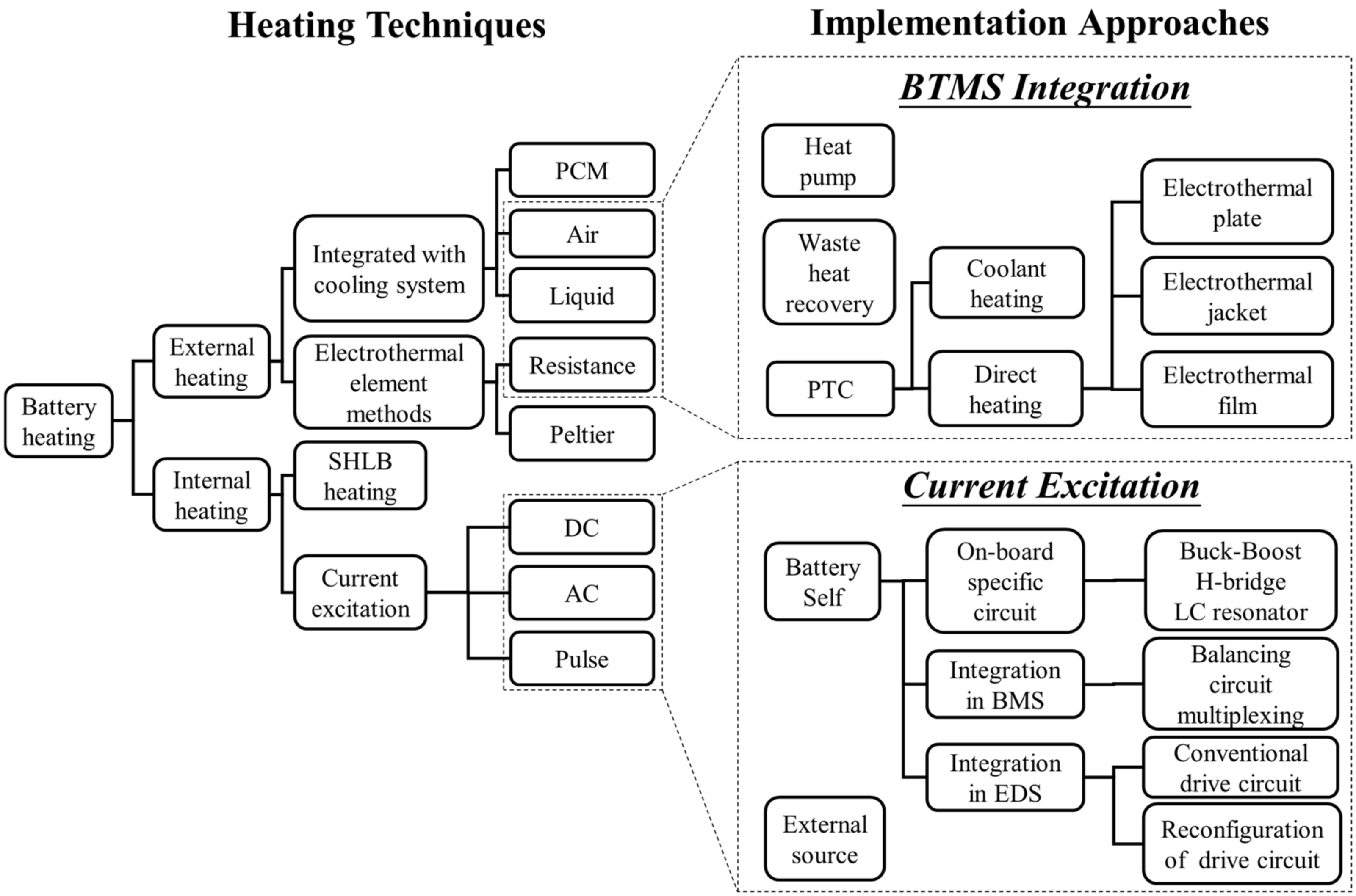
As illustrated in Figure 1, battery heating methods can be broadly categorized into external and internal heating based on the location of the heat source [14]. By employing approaches such as positive temperature coefficient (PTC) resistor, heat pump, and waste heat recovery, external heating is characterized by relatively lower system complexity; however, it presents notable limitations, including reduced efficiency and effect of non-uniform heating [15]. In contrast, internal heating inherently overcomes these disadvantages [16] and has gained widespread recognition for its considerable potential in LiB heating applications.
The current excitation-based battery self-heating represents the most prevalent technology for internal heating applications at present. This approach contributes to the decreased system complexity and cost observed with SHLB batteries [17,18,19], meanwhile avoiding the inconveniences linked to an external power sources [20]. Consequently, it has garnered significant interest among researchers [21]. In general, the on-board battery internal heating methods can be categorized by the on-board specific circuitry [22,23,24,25], integration in the battery management system (BMS) [26,27] or integration in the electric drive system (EDS) [28,29,30,31,32,33]. The on-board specific circuitry approach is recognized for its implementation flexibility. Various types of such heaters exist, primarily based on buck-boost circuits [22], H-bridge configurations [25], and LC resonators [23,24]. In comparison to their benefits, specific circuitry approaches necessitate increased installation space and higher hardware expenses. Meanwhile, key challenges for specific circuitry methods include the independent control of the amplitude and frequency of the heating current, as well as the capability of on-route heating. Alternatively, AC heater can be integrated with the equalizer circuit in BMS [26,27], thereby potentially decreasing hardware expenses and enhancing the power density of the battery system [21]. However, it should be noted that the equalizer circuit in BMS is not a standardized configuration across all EVs in the market.
Based on the integration in EDS, various heating methods have been explored and evaluated. Du et al. [28] propose a heating current control approach utilizing conventional EDS. This approach not only decreases hardware expenses but also gives the possibility of battery on-route heating. However, heating the rate of temperature rise is not sufficient. In addition, the research work does not deep dive into the on-route heating implementation. Li et al. [29,30] introduced the dual-/triple-module separated inverter (DMSI/TMSI) topology, facilitating rapid battery heating. The DMSI/TMSI approach significantly increases the root mean square (RMS) value of the heating current, compared with the conventional drive circuit heating approach. Zhu et al. [31] proposed an integrated battery self-heater (IBSH) together with a robust control method. A fast battery temperature rise can be achieved according to their experimental results. Despite the advantages of the above techniques, DMSI/TMSI and IBSH unfortunately lack the support for the functionality of battery on-route heating. Furthermore, the modification requirements for the battery pack architecture must also be considered when applying DMSI/TMSI. In the IBSH method, the undesired torque is nullified by adjusting the rotor permanent flux to the direction consistent with the excitation flux of the winding, which may restrict the applicability of IBSHs in certain scenarios.
Inspired by previous studies, a novel battery self-heating approach based on drive circuit reconfiguration is introduced in this paper. (1) The proposed neutral point battery heater (NPBH) is compatible with both the preheating mode and on-route heating mode, meanwhile significantly reducing the complexity, cost, and space requirement of the implementation. (2) The undesired torque caused by heating current can be inherently eliminated regardless of the rotor position. This does not necessitate a dedicated control algorithm or mechanical method. (3) The current control of the heating and the driving based on NPBH is fully decoupled. Thus, strategies dedicated to on-route heating can be easily implemented. (4) A significant rate of temperature rise (RTR) for the battery can be achieved using this method.

2. Proposed NPBH Method and Modeling Approach

2.1. Operating Principle

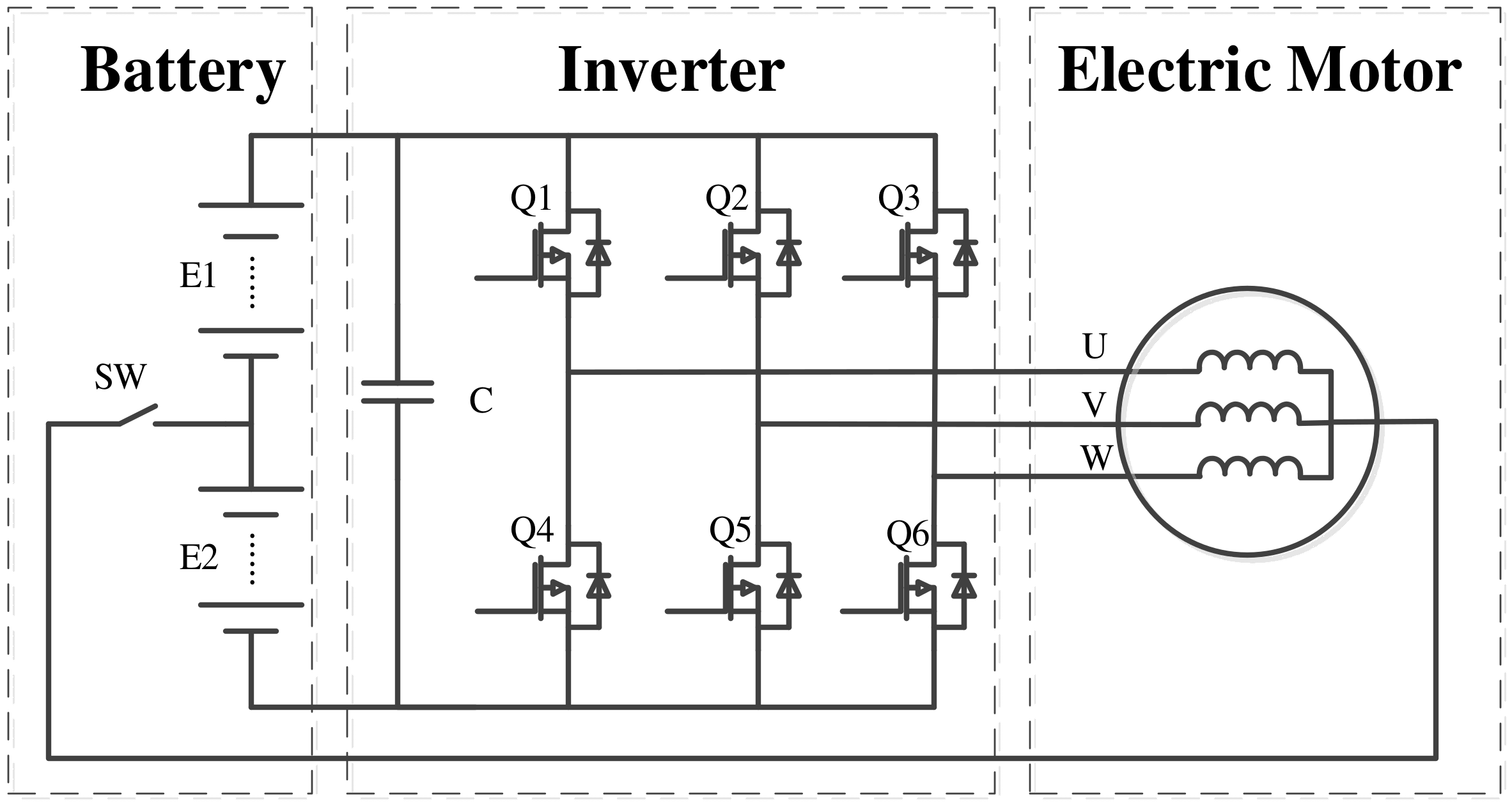
The circuit topology of NPBH is shown in Figure 2. E1 and E2 are two identical battery modules in series, providing the DC-bus voltage. C is the DC-bus capacitor of the inverter. Power electronic transistors Q1 and Q4 constitute the first bridge arm of the inverter, which is connected to the U phase of the electric motor (EM) winding. Similarly, transistors Q2 and Q5 comprise the second bridge arm, linked to the V phase of the EM winding. Lastly, transistors Q3 and Q6 form the third bridge arm, associated with the W phase of the EM winding. The neutral point of EM connects with the mid-point of the battery pack through switch SW.
When the battery temperature is low and heating is required, SW switches to on-state. The energy stored in E1, E2, and the windings of the EM is alternately charged and discharged by control. The common component of the current within each winding phase functions as the heating current, whereas the differential component of the current in each phase produces the driving torque. When the battery is warmed up, SW switches to off-state. The neutral point EM can be controlled as a normal motor.
Employing the NPBH circuit, the zero-axis current i0 circulates continuously between EM windings and battery modules via the inverter and the EM neutral line. Within every switching cycle, the current evolution can be separated into different stages. Zero voltage vectors (Q1Q2Q3 command:000 or 111) are adopted for the synchronous control of the inverter arms to precisely regulate i0 which serves as the heating current.
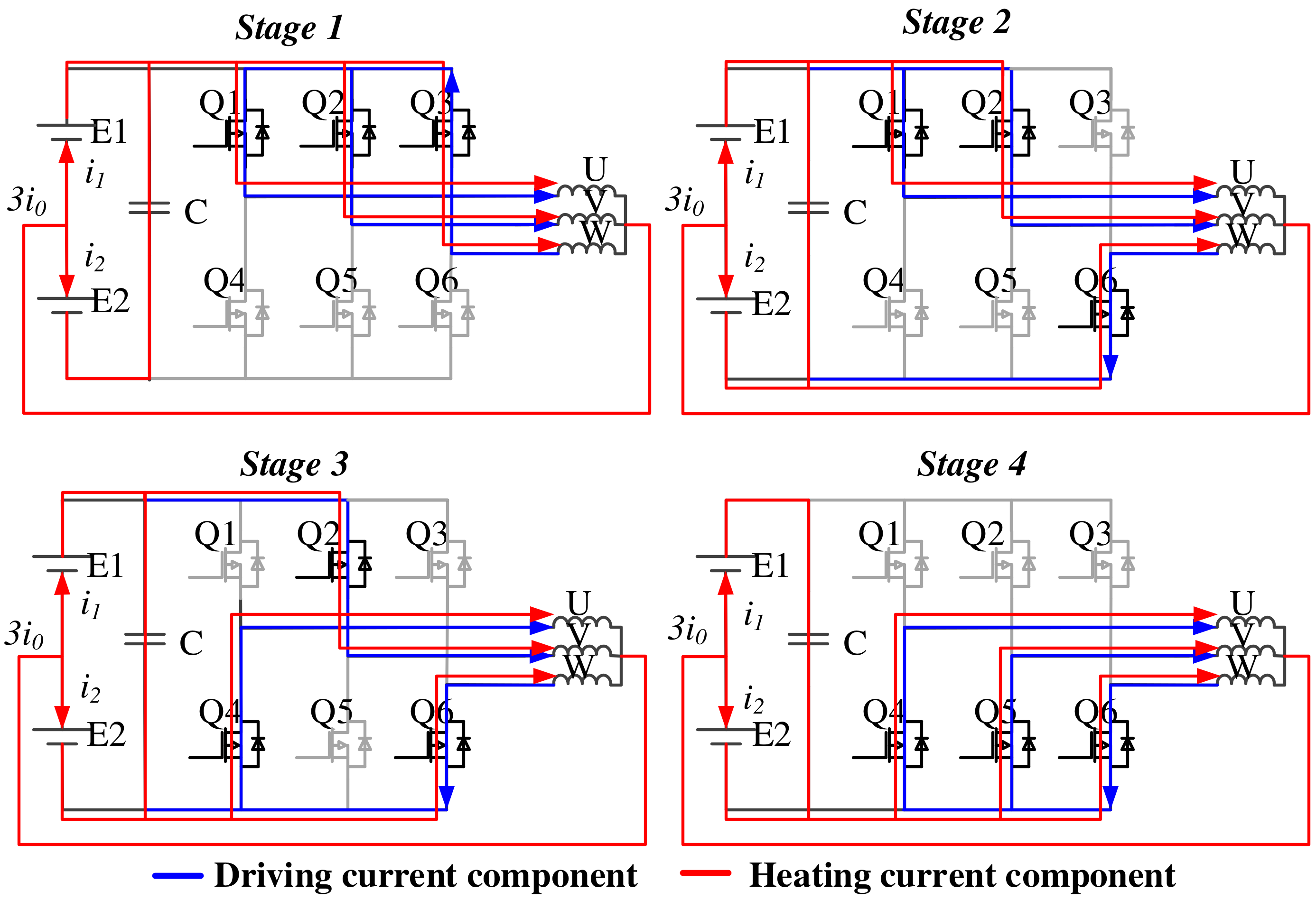
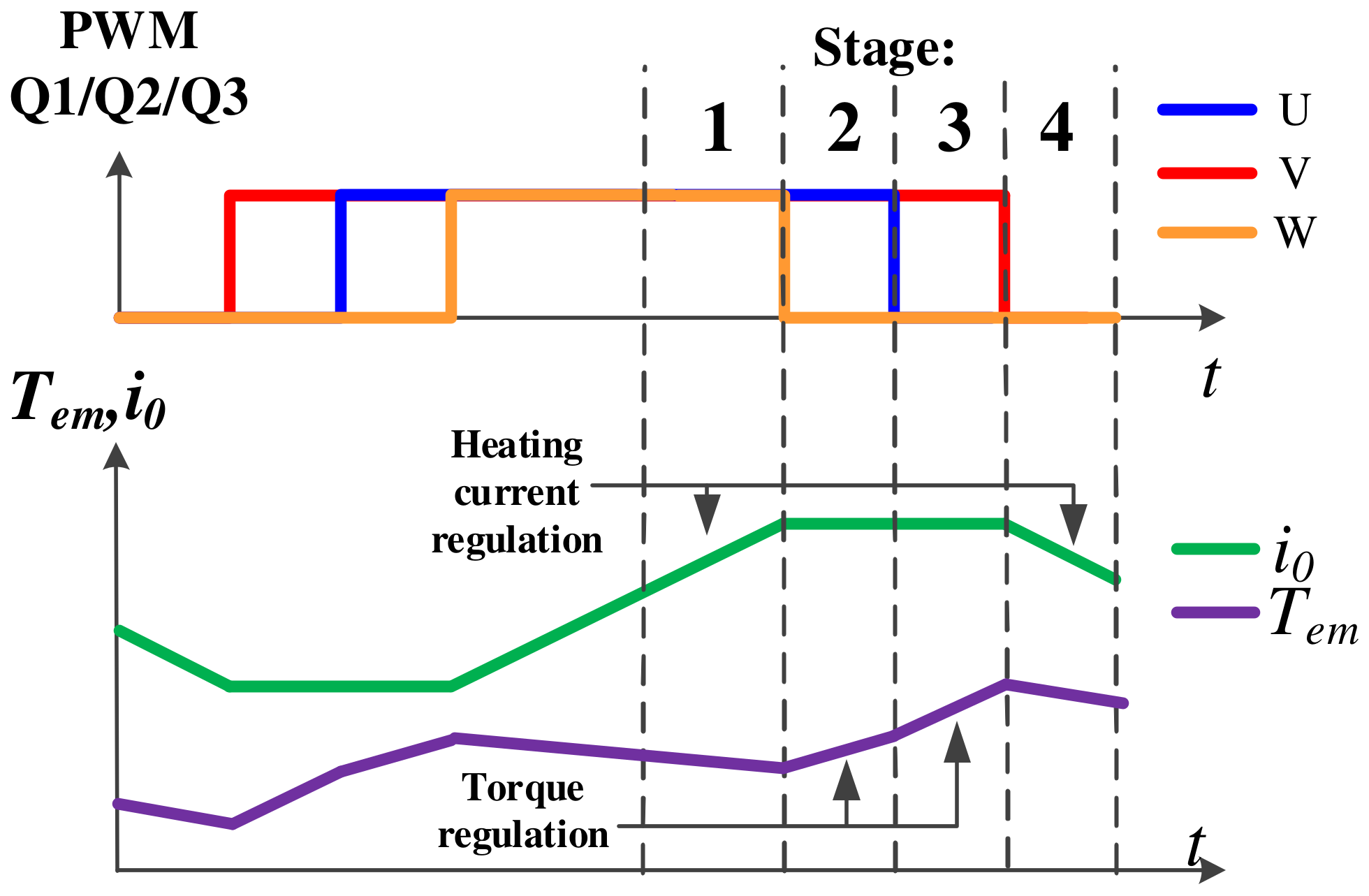
Figure 3 shows the four stages of the circulation of the heating and the driving current in a single operating cycle, given a rotor electrical angle of π/2. Figure 4 depicts the temporal relationship between the PWM signals and the zero-axis current i0, where the positive direction of current flow is defined as originating from the U, V, and W phase terminals toward the motor neutral point. Since the PWM signals are generated center-symmetrically, it suffices to analyze half of the control cycle, which is divided into four stages with the current component of driving represented in blue and the component of heating represented in red. i1 and i2 represent the current component of heating passing through the upper battery module E1 and the lower battery module E2, respectively.
During Stage 1, Q1, Q2, and Q3 are in the on-state, resulting in a freewheeling state of the driving current. The torque gradually decreases while the heating current i0 increases. The upper battery module is charged while the lower is discharged. The EM windings store the energy whereas the DC-bus capacitor releases the energy. In Stage 2, Q3 is turned off and Q6 is turned on, which leads to an increase in the driving torque while i0 remains essentially constant. In Stage 3, Q1 is switched off and Q4 is switched on. Similar to Stage 2, the driving torque keeps increasing and the heating current remains largely unchanged. In Stage 4, Q2 turns off and Q5 turns on. The driving current is in the freewheeling state. Both the torque and i0 decrease. The upper battery module is discharged while the lower is charged; the EM winding releases energy whereas the DC-bus capacitor stores energy.
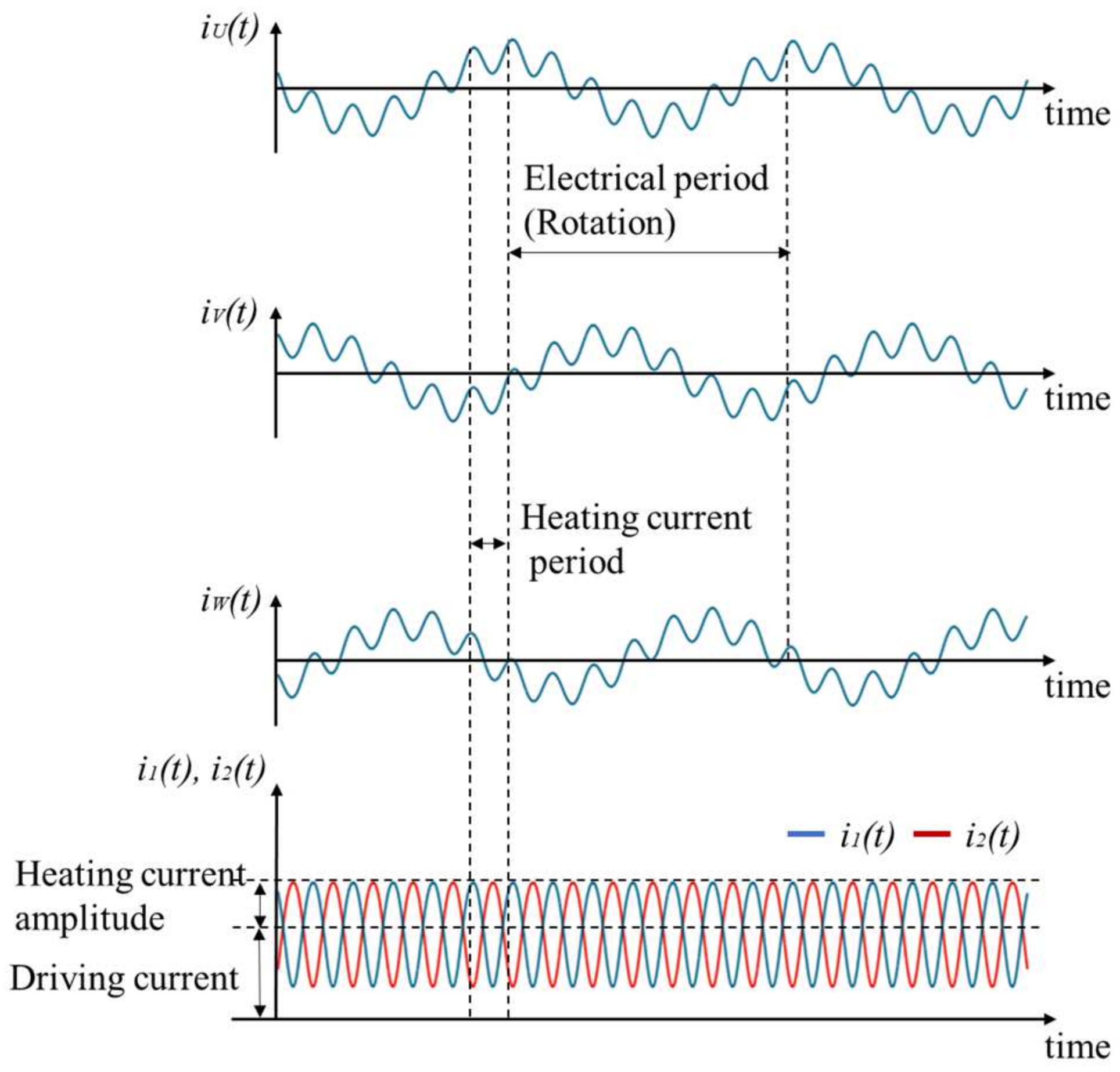
In a close-loop operation, a reference of sinusoidal waveform is tracked by i0 using the PI-based current controller. Since E1 and E2 have identical parameters, i1 and i2 have the same amplitude but opposite phases, as shown in Figure 5. The amplitude of the heating current Iheat can be obtained by (1), ignoring the losses of the wire and the inverter.
I h e a t = i 1 = i 2 = 3 2 i 0 .

2.2. Control Method

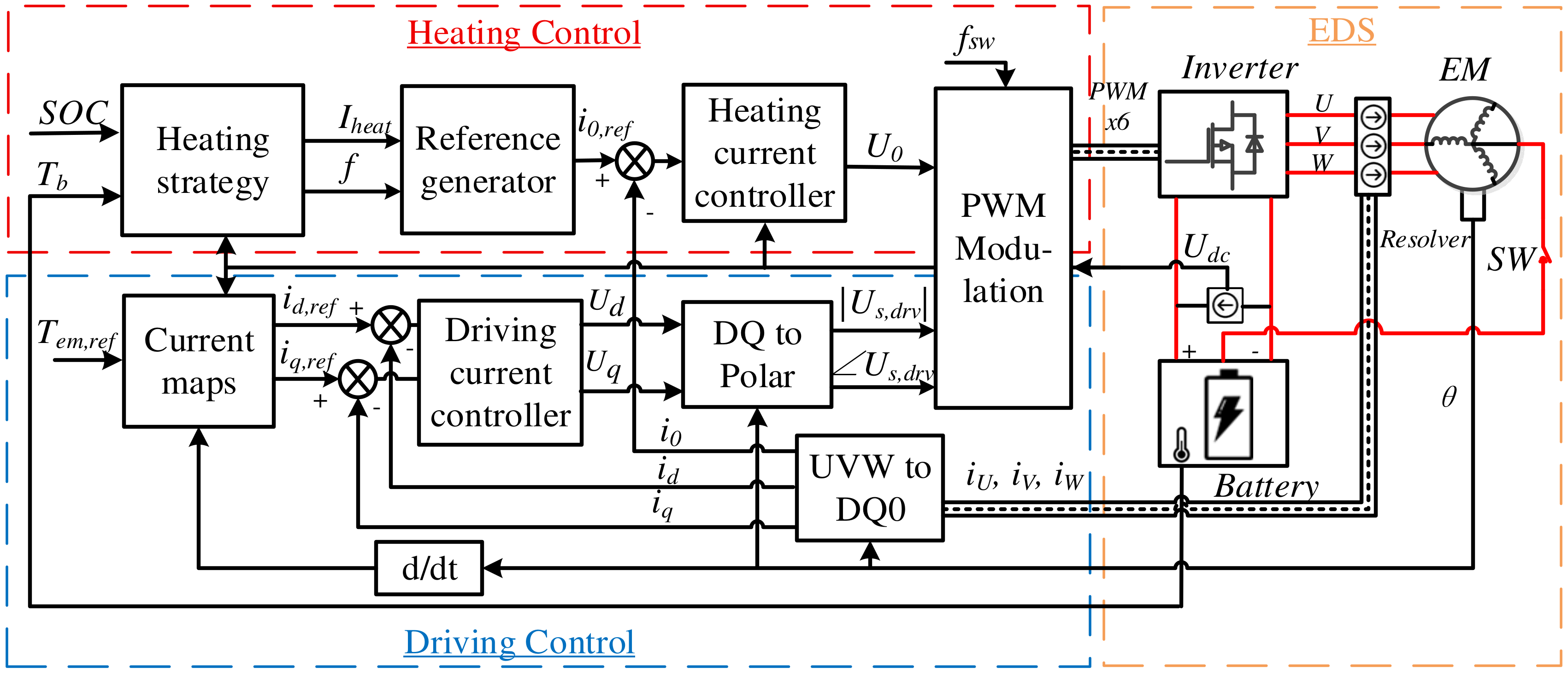
The entire control logic of the NPBH contains the regulation of both heating and driving currents, as illustrated in Figure 6. A heating strategy determines the optimal amplitude Iheat and frequency f of the heating current, according to battery SOC and temperature Tb. When on-route heating is applied, Iheat and f can also be affected by driving torque Tem, battery pack voltage Udc, as well as vehicle speed.
For heating current control, the duty cycle of PWMαh can be obtained by Equation (2).
α h = 2 U d c K 0 , P i 0 , r e f i 0 + K 0 , I i 0 , r e f i 0 d t ,
where i0,ref is the reference of i0. K0,P and K0,I represent the factors of proportional and integral parts of the controller, respectively. The currents for driving, namely id and iq, are regulated using the Field-Oriented Control (FOC). The duty cycles for driving, αu,drv, αv,drv and αw,drv, can be determined by bipolar sinusoidal pulse width modulation (SPWM) according to the phase voltage calculated by FOC, as shown in Equation (3).
α u , d r v = U s , d r v · cos U s , d r v U d c + 0.5 α v , d r v = U s , d r v · cos U s , d r v 2 3 π U d c + 0.5 α w , d r v = U s , d r v · cos U s , d r v + 2 3 π U d c + 0.5 ,
where |Us,drv| and ∠Us,drv are the module and phase angles of the phase voltage Us,drv. The applied duty cycles for three inverter phases, namely αu, αv and αw, are the superposition of the heating component and driving component, as presented in Equation (4).
α u = α u , d r v + α h α v = α v , d r v + α h α w = α w , d r v + α h .
It should be noted that the driving current also contributes to warm the battery during the on-route heating process. This effect is considered in the heating strategy and will be discussed in the next subsection.

2.3. LiB Electro-Thermal Model

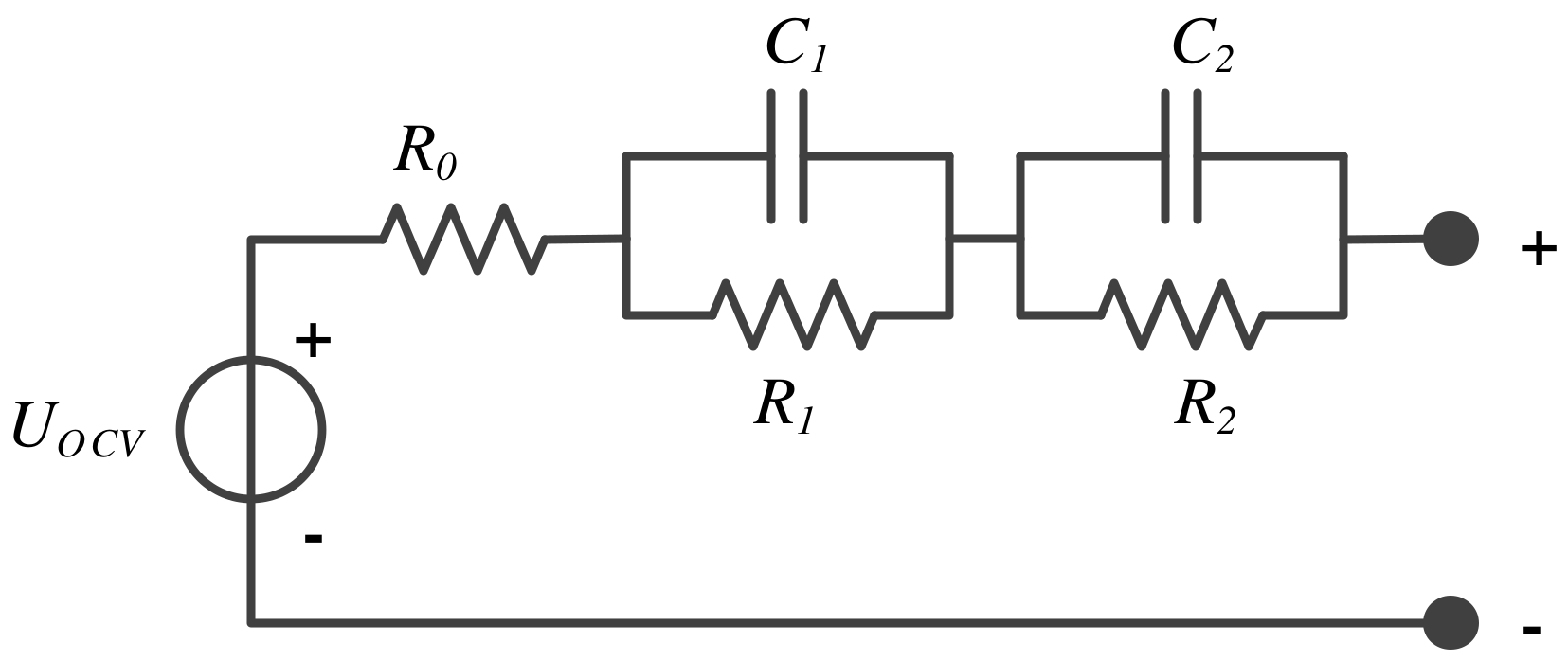
It is well established that the impedance characteristics of LiBs are influenced by temperature, SOC, and current frequency. These dependencies can be effectively captured through an equivalent circuit model (ECM) derived from the fitting of electrochemical impedance spectroscopy (EIS) test data. Figure 7 illustrates the second-order ECM employed in this study. UOCV represents the open circuit voltage of the battery; R0 is the ohmic resistance; R1 and R2 represent the equivalent resistance of the first and the second orders, respectively; C1 and C2 represent the corresponding capacity of the time constant for the first and the second orders. The battery impedance can be calculated by Equation (5):
Z T b , S O C , f = R 0 + R 1 1 + ( 2 π f ) 2 R 1 2 C 1 2 + R 2 1 + ( 2 π f ) 2 R 2 2 C 2 2 j 2 π f · R 1 2 C 1 1 + ( 2 π f ) 2 R 1 2 C 1 2 + 2 π f · R 2 2 C 2 1 + ( 2 π f ) 2 R 2 2 C 2 2 ,
where f is the frequency of the current; Z represents the battery impedance. Since the internal heating has an excellent heating uniformity, it is reasonable to assume that no temperature gradient exists inside the battery. According to energy conservation, the temperature evolution of battery Tb can be expressed as follows.
m b C p d T b d t = q h q d ,
where mb and Cp represent the cell mass and specific heat, respectively. qh and qd represent the heat generated and dissipated of the cell. Ignoring the impact of transient torque changes on the heat generation, qh can be calculated by Equation (7).
q h = I d 2 Re ( Z ) | f = 0 + I h 2 Re ( Z ) | f = f h with I d = 3 | U S , d r v | I d r v cos φ 2 U d c η e , I h = I h e a t 2 ,
where Id and Ih represent the RMS value corresponding to the driving current and the heating current, respectively, observed from the battery side; φ is the power factor of the EM. Re(Z) is the real part of battery impedance. It is the function of SOC, temperature, and current frequency. ηe represents the efficiency of EDS. The dissipated heat qd can be expressed as follows.
q d = h A b ( T b T a ) ,
where h is the heating transfer coefficient. Ab represents the heat exchange area of the battery. Ta represents the ambient temperature. Since the mean value of the heating current is zero, the SOC progression during on-route heating can be determined using the following calculation.
d S O C d t = I d C b ,
where Cb represents the nominal capacity of the battery.

2.4. Elimination of Undesired Torque

As is well known, the heating current through the windings of EM may generate undesired torque, resulting in the vibration or movement of the vehicle. Therefore, it is necessary to analyze the electromagnetic influence caused by the heating current. On neglecting the leakage inductance of the phase windings, the self and mutual inductance of the phase winding can be expressed as follows.
L u u = ψ u u i u , h = L s 0 + L s 2 cos 2 θ L v v = ψ v v i v , h = L s 0 + L s 2 cos 2 ( θ 2 3 π ) L w w = ψ w w i w , h = L s 0 + L s 2 cos 2 ( θ + 2 3 π ) L u v = L v u = L s 0 2 + L s 2 cos 2 ( θ + 2 3 π ) L u w = L w u = L s 0 2 + L s 2 cos 2 ( θ 2 3 π ) L v w = L w v = L s 0 2 + L s 2 cos 2 θ with L s 0 = ( 2 π N p h k w ) 2 · τ l p · λ δ 0 L s 2 = 1 2 ( 2 π N p h k w ) 2 λ δ 2 ,
where Lxy represents the self of mutual inductance between the EM winding phases x and y. ψx is the flux linkage of the winding phase x. iu,h, iv,h, and iw,h are the current components of heating flowing through each phase. θ is the rotor electrical angle. Nph is the total winding turns of a single phase. kw is the winding factor. τ denotes the pole pitch of the EM. l is the stack length of EM. λδ0 and λδ2 are the relative permeance of the air gap corresponding to the zero-order and the second-order harmonics, respectively. Therefore, the inductance matrix of the EM, namely LS, can be expressed as follows.
L s = L u u L u v L u w L v u L v v L v w L w u L w v L w w ,
The electromagnetic torque Tem is calculated by Equation (12).
T e m = p · i u , h i v , h i w , h T · L s · i u , h i v , h i w , h ψ f · sin θ sin θ 2 π 3 sin θ + 2 π 3 ,
where p denotes the number of the pole pairs of the EM. ψf is the permanent flux linkage of the EM. Neglecting the harmonics caused by PWM modulation, the current component of heating in a single phase can be expressed as follows.
i 0 = i u , h = i v , h = i w , h = 2 3 I h e a t sin ( ω t ) ,
where ω is the angular velocity of the sinusoidal heating current. t represents the time. By substituting Equation (13) into Equation (12), the electromagnetic torque can be rewritten as follows.
T e m = p · i 0 · ψ f · [ sin θ + sin ( θ 2 3 π ) + sin ( θ + 2 3 π ) ] i 0 · [ L s 2 cos ( 2 θ ) + L s 2 cos ( 2 θ 4 3 π ) + L s 2 cos ( 2 θ + 4 3 π ) ] i 0 · [ L s 2 cos ( 2 θ 4 3 π ) + L s 2 cos ( 2 θ ) + L s 2 cos ( 2 θ + 4 3 π ) ] i 0 · [ L s 2 cos ( 2 θ + 4 3 π ) + L s 2 cos ( 2 θ 4 3 π ) + L s 2 cos ( 2 θ ) ] = 0 .
According to Equation (14), it can be derived that the torque constantly equals zero regardless of rotor electric angle θ and current phase ωt. In other words, NPBH can inherently eliminate the undesired torque caused by the heating current.

2.5. Decoupling of Heating and Driving Currents

In on-route heating scenarios, it is essential to decouple the current control of heating and driving. Taking the driving current into consideration, the phase current can be reformulated as Equation (10):
i U = i u , h + i u , d r v = 2 3 I h e a t sin ( ω t ) + I d r v cos ( θ + ϕ ) i V = i v , h + i v , d r v = 2 3 I h e a t sin ( ω t ) + I d r v cos ( θ 2 3 π + ϕ ) i W = i w , h + i w , d r v = 2 3 I h e a t sin ( ω t ) + I d r v cos ( θ + 2 3 π + ϕ ) ,
where iU, iV, iW are the total current of each phase respectively. iu,drv, iv,drv, iw,drv are the current components of driving for each phase respectively. Idrv is the amplitude of the driving current component. ϕ is the current advanced angle. Upon transforming from the stationary frame to the rotational frame, the currents can be represented as follows.
i d i q i 0 = C i U i V i W = I d r v cos ( β ) I d r v sin ( β ) 2 3 I h e a t sin ( ω t ) , with C = 2 3 cos θ cos ( θ 2 3 π ) cos ( θ + 2 3 π ) sin θ sin ( θ 2 3 π ) sin ( θ + 2 3 π ) 1 2 1 2 1 2 ,
where id, iq are the currents in the direct axis (D-axis) and quadrant axis (Q-axis) respectively. C represents the Clarke–Park transformation matrix. β is the phase angle of the driving current. According to Equation (12), the electromagnetic torque can be reformulated as follows.
T e m = 3 2 p i q i d ( L d L q ) + ψ f , with L d L q L 0 = C L s C 1
where Ld, Lq, and L0 are the inductance in the D-axis, Q-axis, and Zero-axis respectively. ψf represents the permanent magnetic flux linkage. As can be noticed, id and iq are determined by the amplitude Idrv and the phase angle β of driving current control according to Equation (16), while i0 is determined by amplitude Iheat and the phase angle ωt of the heating current. There is no influence by i0 on driving torque Tem according to Equation (14). Consequently, the controls of heating and driving are completely decoupled.

3. Experiment Design and Setup

3.1. Testbench Setup

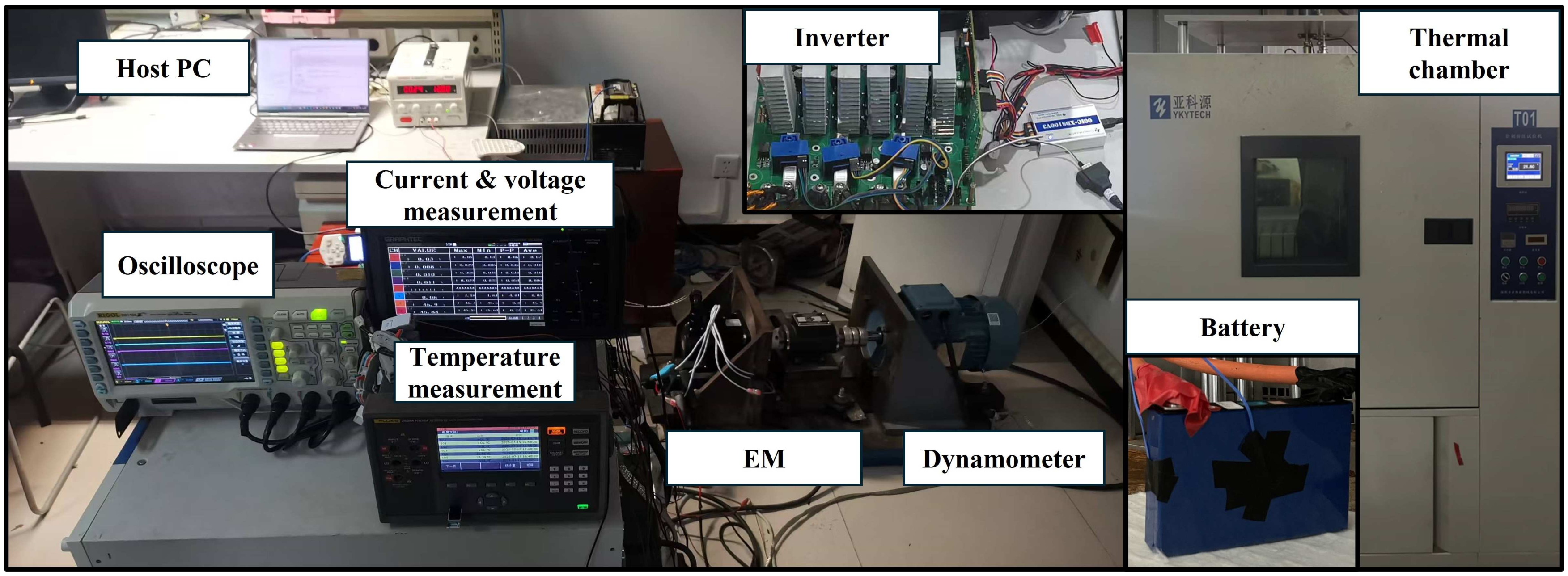
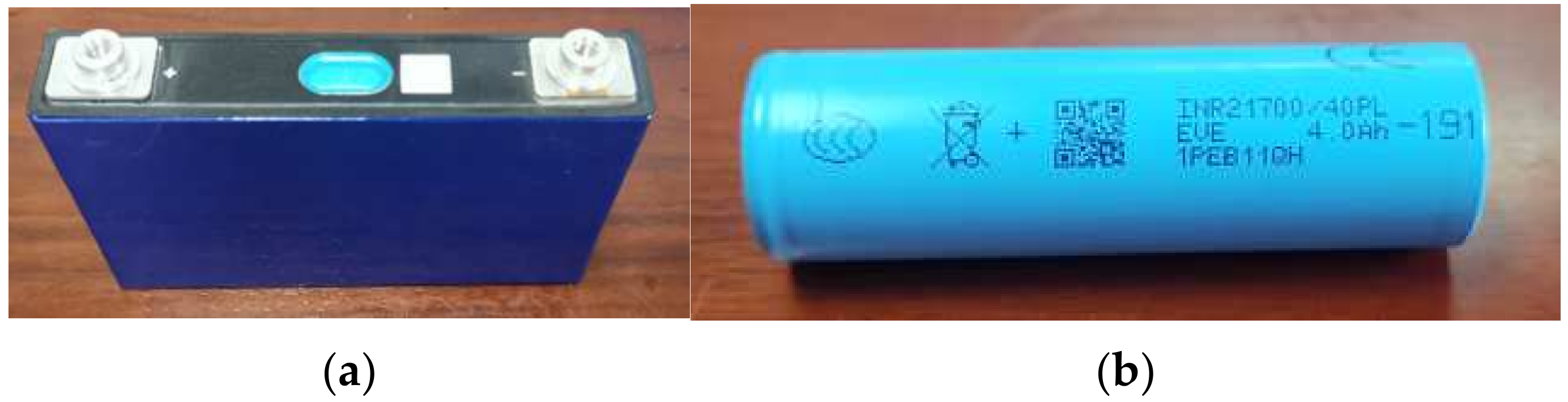
As shown in Figure 8, an EDS testbench with a battery thermal chamber is built to validate the proposed NPBH working principle and the battery electro-thermal modeling approach. Given that the rated phase current of the EM on the testbench is 10 A, a cylindrical battery with capacity of 4 Ah is selected for the validation experiments of the on-route heating to achieve an observable temperature rise compared to the battery with large capacity. Conversely, a prismatic battery with a capacity of 58 Ah is utilized for the validation of preheating under large currents, as shown in Figure 9. Since no back electromotive force exists in the circuit during the preheating phase, three identical 10 uH discrete inductors with high current-through capability are employed to replace the EM, emulating the phase inductance of the windings. The parameters of the EM on the testbench and the batteries are shown in Table 1 and Table 2, respectively.
An assembled 24-Series battery pack is shelved in the thermal chamber with a constant ambient temperature. Before the beginning of each test, a 12 h rest duration for the battery is applied to ensure that the interior of each cell is completely frozen. A data collector is utilized to record the voltage of the upper and lower battery modules (1000 sample/s), the current-through battery pack positive wire, the negative wire, the EM neutral wire (1000 sample/s), and the temperatures of the cells (0.5 sample/s), respectively. The 3 K-type thermal couplers are mounted on the body and the tabs of each cell. Their average value is considered as the battery temperature.

3.2. Experimental Design

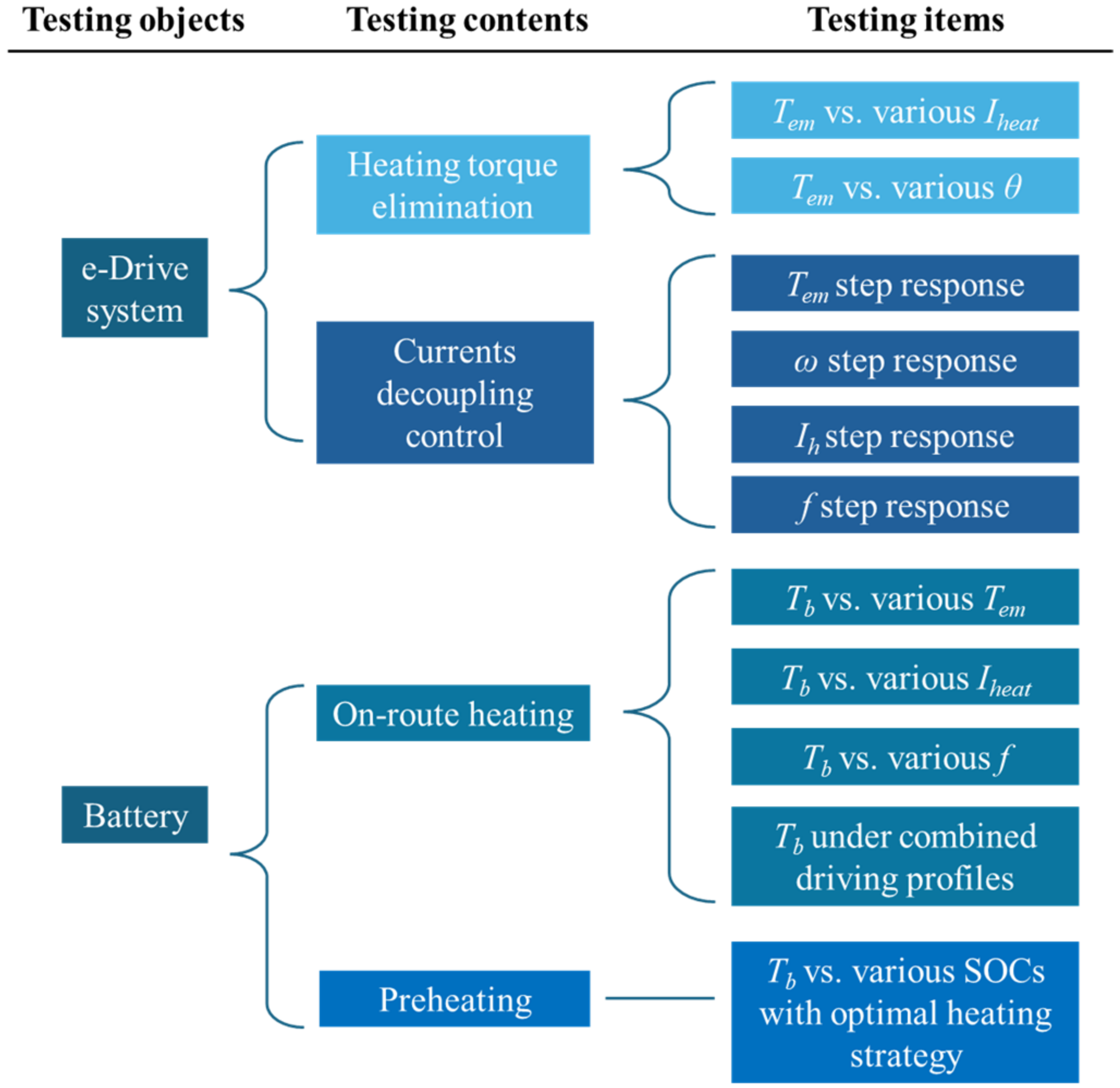
The experiments are primarily categorized into control validation for the NPBH and electro-thermal modeling validation for the battery, as illustrated in Figure 10. The control validation is further divided into the test groups of heating torque elimination and currents decoupling control. In the heating torque elimination test group, the torque is measured under various heating current amplitudes Iheat and rotor angles. In the current decoupling control test group, the independence of controlled variables and their dynamic responses are observed. On the other hand, the battery electro-thermal model is validated by observing the battery temperature rise under different conditions. Two distinct testing groups are included: (1) on-route heating tests; (2) preheating tests with the optimal strategy [33].
The experiments investigating the elimination of heating torque utilize the cylindrical battery as the power source. The torque is measured under different heating current amplitudes and rotor angles in the stationary state. The angular period of torque fluctuation can be determined by 360°/(4 pairs x 3 phases) = 30°. Detailed experimental conditions are shown in Table 3.
The validation for decoupling control consists of four test groups. Each group varies a single variable across three different levels while keeping the other variables constant. Detailed experimental conditions are shown Table 4.
The validation of on-route heating can be divided into the test group under fixed conditions and the test group under combined conditions. In the experimental design of on-route heating under fixed conditions, the rotor speed is maintained constant at 100 rpm. Since variations in either torque or speed will result in changes in Id, only the influence of different torque levels on battery temperature is observed. Detailed experimental conditions are shown Table 5.
Two tests of combined conditions are designed to more realistically emulate the on-route heating scenarios since the rotational speed of the dynamometer on the testbench can be adjusted solely through manual control. The first emulates an aggressive driving behavior. The vehicle starts up with elevated torque, which progressively diminishes as the velocity increases. On the other hand, as the driving current decreases, more current is released to heating the battery. In the final stage of the combined conditions, the effect of current frequency adjusted by the heating strategy is emulated.
The second profile of combined conditions mimics a gentle driving style typical in urban areas. The vehicle starts up with low driving torque, so that more current can be released to heat the battery compared to the first profile. A higher frequency is applied at the beginning to prevent the battery’s terminal voltage from exceeding the cut-off threshold. As the battery temperature gradually rises, the frequency is gradually lowered down to achieve the heat generation as high as possible while maintaining the heating current amplitude. Detailed experimental conditions are shown Table 6.
For the preheating validation, the heating process is evaluated at SOCs of 30%, 60% and 80%. To simplify the control, the amplitude and frequency of the optimal heating current according to the battery impedance characteristics are regulated with a temperature step of 5 °C [33]. The parameter values of set points for each temperature and SOC are listed in Table 7. It should be noted that the heating current parameters here are optimized based on the EIS impedance characteristics of the fresh battery. As the battery degrades during usage, the heating current parameters should be periodically updated according to the battery’s SOH (state of health).

4. Results and Discussion

4.1. Validation of Torque Elimination

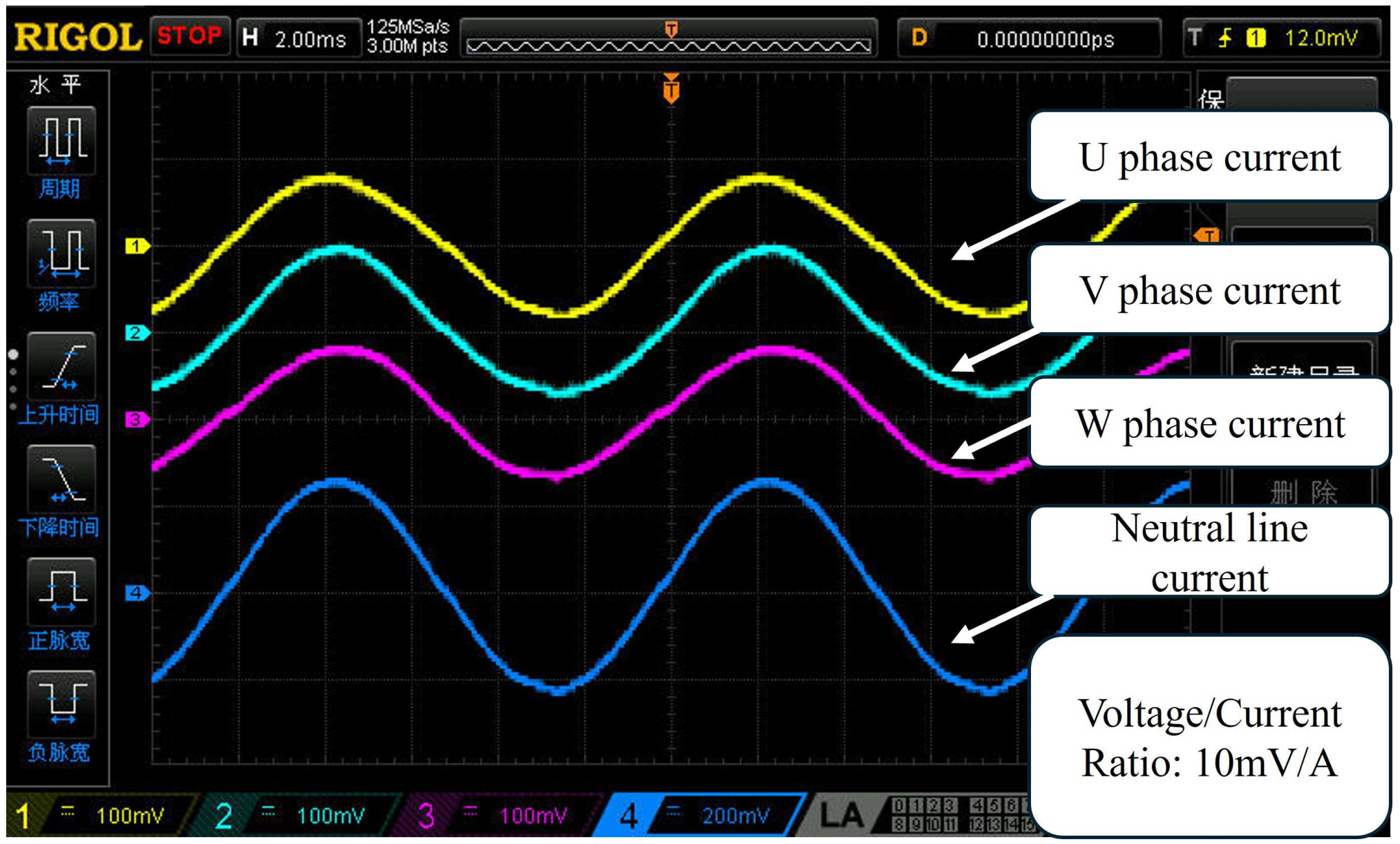
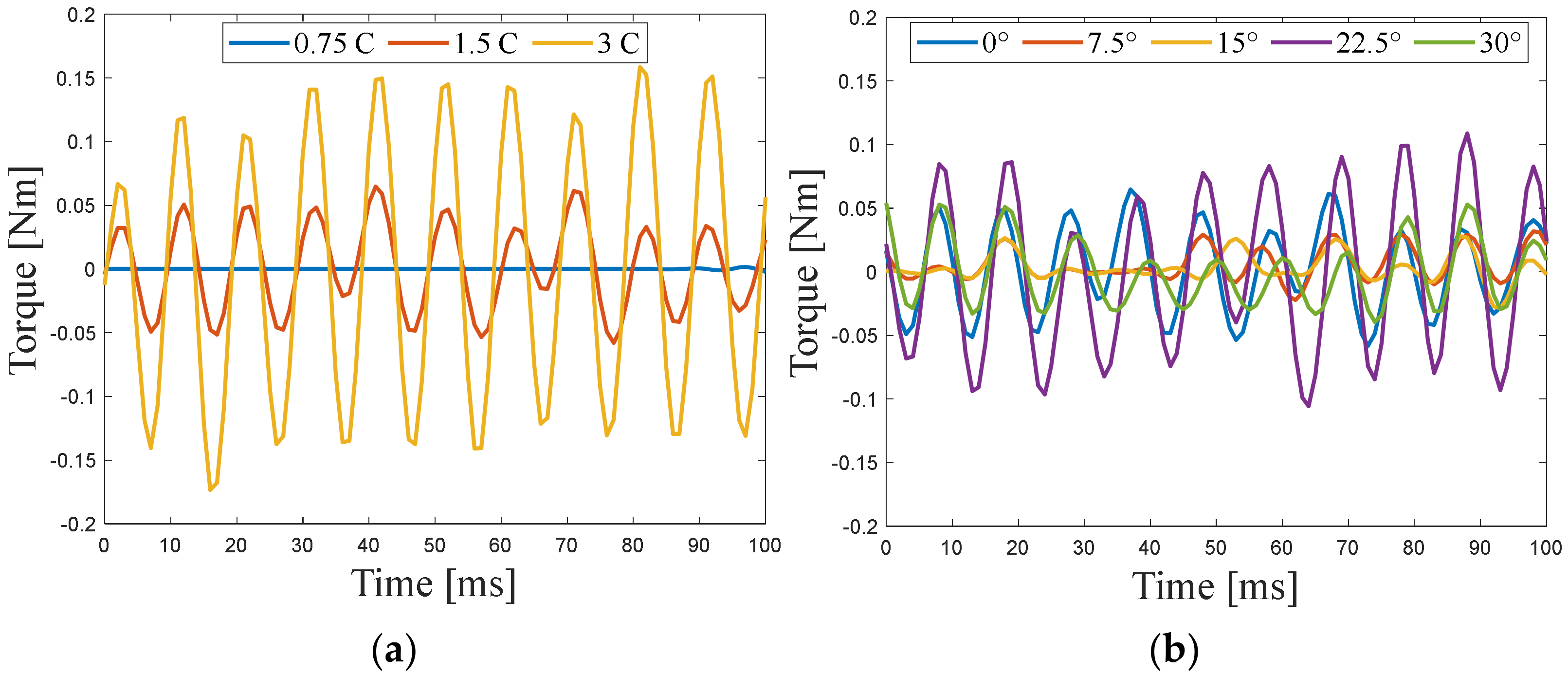
Figure 11 presents the current waveforms through phase and neutral wires with amplitudes of 3 C under preheating conditions. It is evident that the amplitude of the current in the neutral wire of EM is the sum of the current in each phase (three times i0). Figure 12a illustrates the torque fluctuation at the heating current amplitudes of 0.75 C, 1.5 C, and 3 C, respectively. The result indicates that an increase in the heating current amplitude is associated with a deterioration in torque fluctuations. Additionally, Figure 12b presents the torque fluctuations at rotor angles of 0°, 7.5°, 15°, 22.5°, and 30°. It can be seen that their magnitudes demonstrate a periodic pattern. In both cases, the magnitude of torque fluctuations remains below 0.2 Nm, suggesting that the operational influence of NPBH on electromagnetic torque is acceptable. In practice, due to the constraints of the EM electromagnetic structure, rotor torque fluctuations cannot be completely eliminated; meanwhile, the alternating changes in radial magnetic flux density also cause vibration noise in the stator. Therefore, during long-term use, regular inspections are necessary to ensure that the mechanical connections in EDS remain secure, preventing loosening that could lead to accidents.

4.2. Validation of Decoupling Control of Current

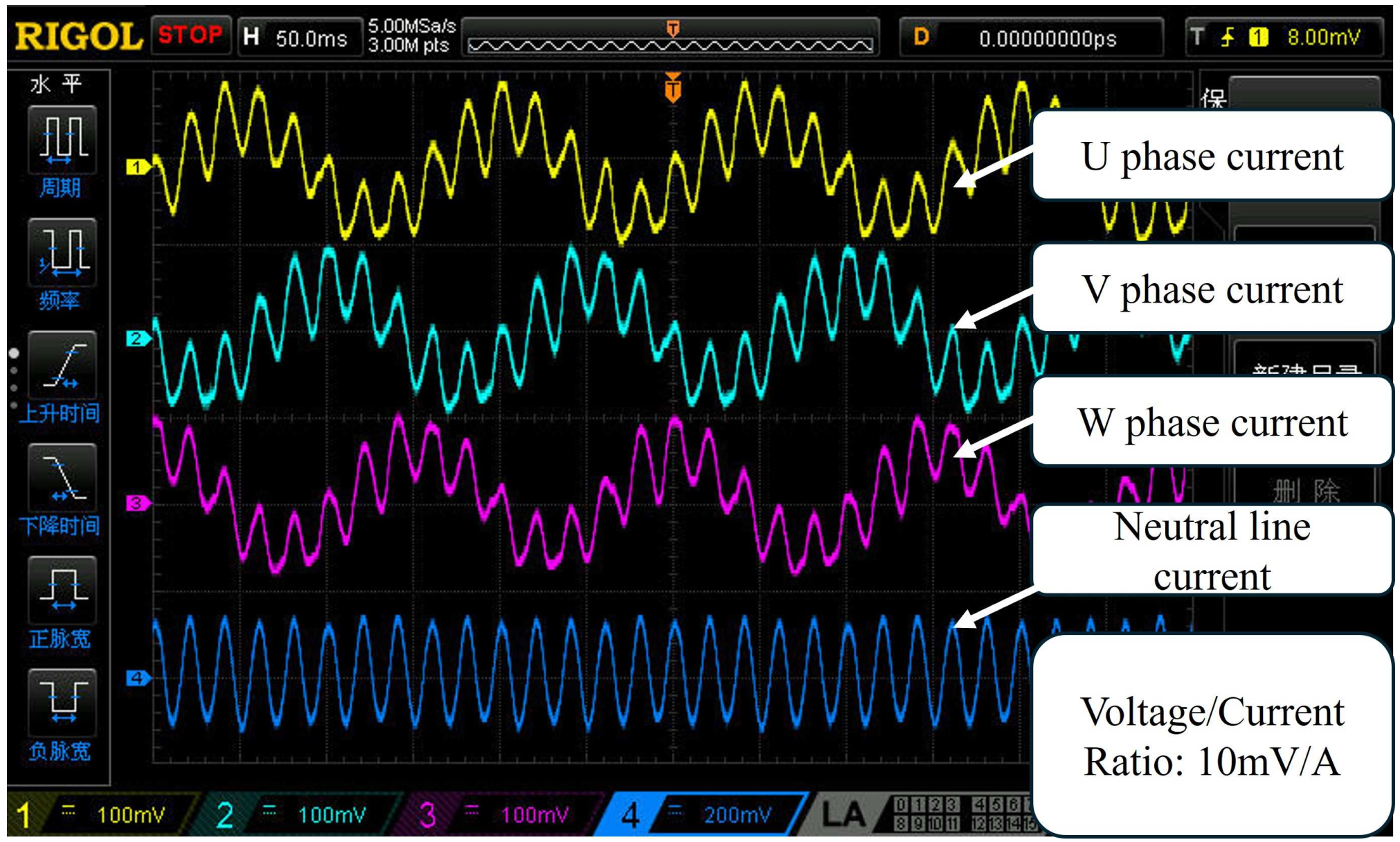
Figure 13 presents the current waveforms through each phase and the neutral wire when the heating and driving components coexist. The picture from the oscilloscope distinctly reveals two eigen frequencies. One corresponds to the rotation speed at 6.67 Hz, and the other, at 50 Hz, is attributed to the heating. Notably, the current component associated with rotation in the neutral wire is nullified due to the displacement of 2π/3 among the three phases, resulting in the exclusive presence of the heating current. Consequently, the current in the neutral wire remains three times the magnitude of i0.
The independence of the driving and heating controls when there is on-route heating is depicted in Figure 14. Specifically, Figure 14a presents stepwise changes in the rotational speed, increasing from 100 rpm to 150 rpm and subsequently to 200 rpm. Concurrently, Figure 14b illustrates stepwise changes in the torque, rising from 0 Nm to 3 Nm and then to 6 Nm. Notably, these variations in driving parameters do not give any affection to i0. Similarly, Figure 14c depicts stepwise adjustments in Iheat, from 0 C to 1.125 C and then to 2.25 C, while Figure 14d shows stepwise reductions in f, decreasing from 50 Hz to 30 Hz and subsequently to 10 Hz. Importantly, these modifications in the heating current do not affect the driving torque.
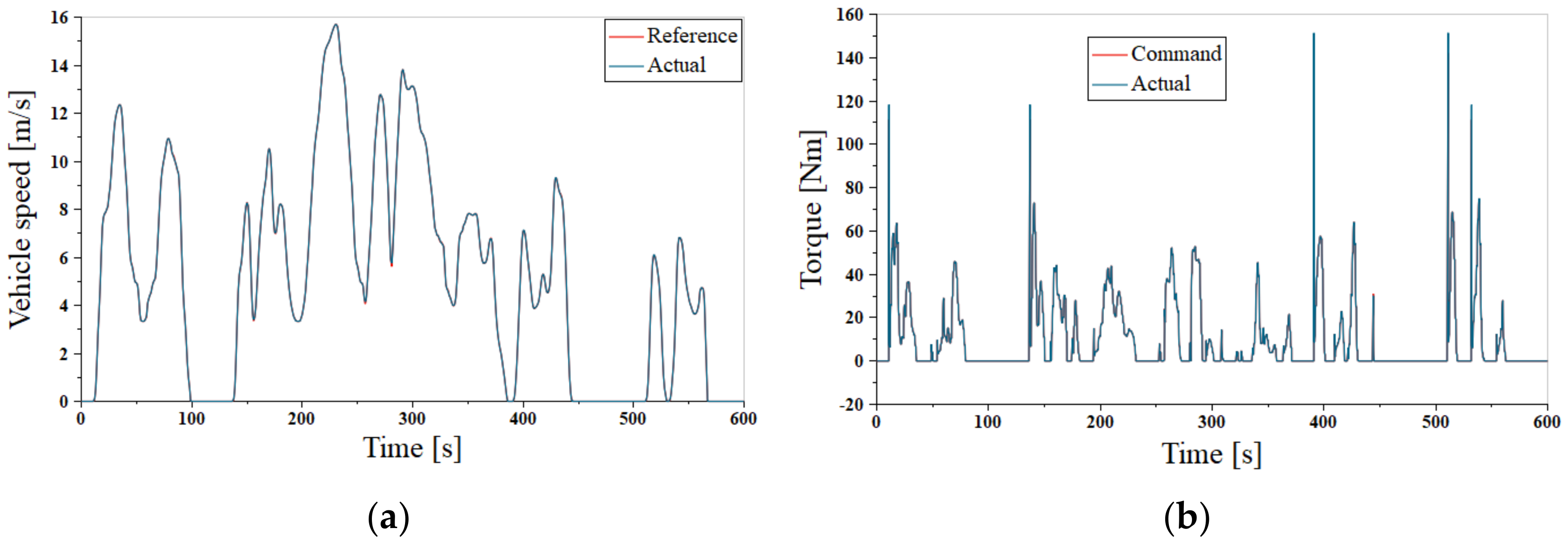
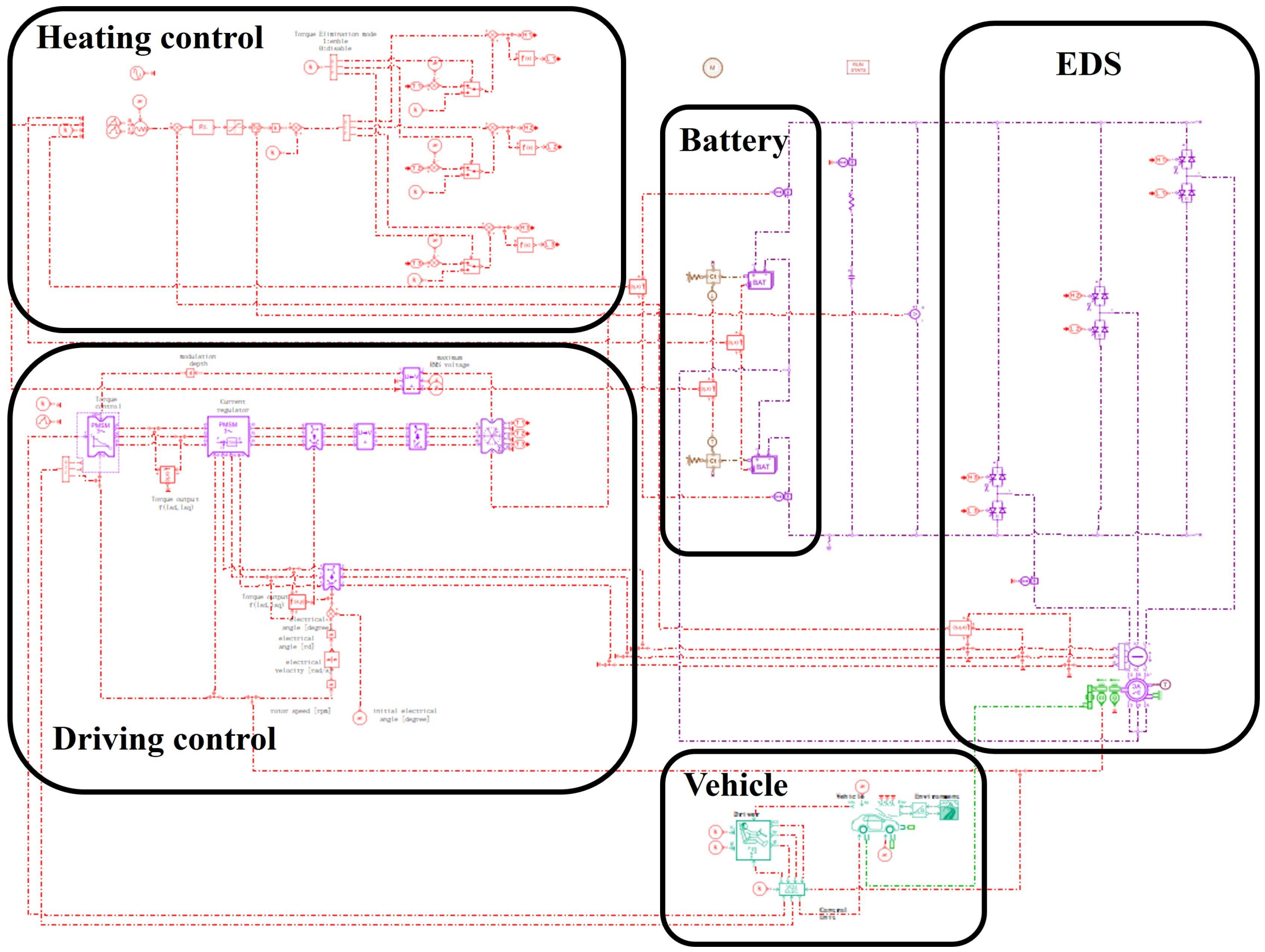
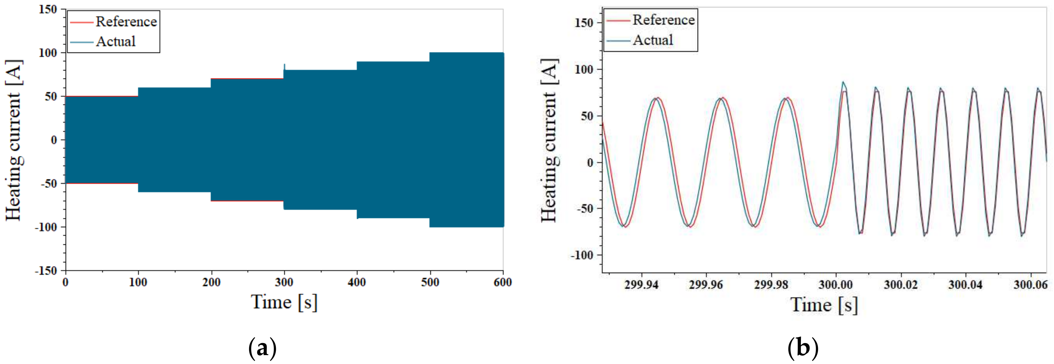
To further demonstrate the decoupled control of driving and heating currents using the proposed heating approach under dynamic driving conditions, a simulation verification is carried out based on the WLTC driving cycle, as shown in Figure 15. The integrated model including the heating and driving control, battery, EDS and vehicle dynamics is built up. Within the first 10 min after vehicle startup, the amplitude of the heating current in the single phase i0 starts at 50 A and increases stepwise by 10 A every 100 s. The frequency f is set to 50 Hz for the first 5 min and then 100 Hz for the following 5 min.
As shown in Figure 16a,b, during dynamic driving cycle, the proposed control method enables the vehicle to accurately follow the reference speed and torque profile. Meanwhile, the heating current is not affected by the control of the driving current. Throughout the on-route heating process, the current consistently maintains a rapid response to the changes in amplitudes and frequencies, as illustrated in Figure 17a,b.

4.3. Validation of NPBH Performance in On-Route Heating Mode

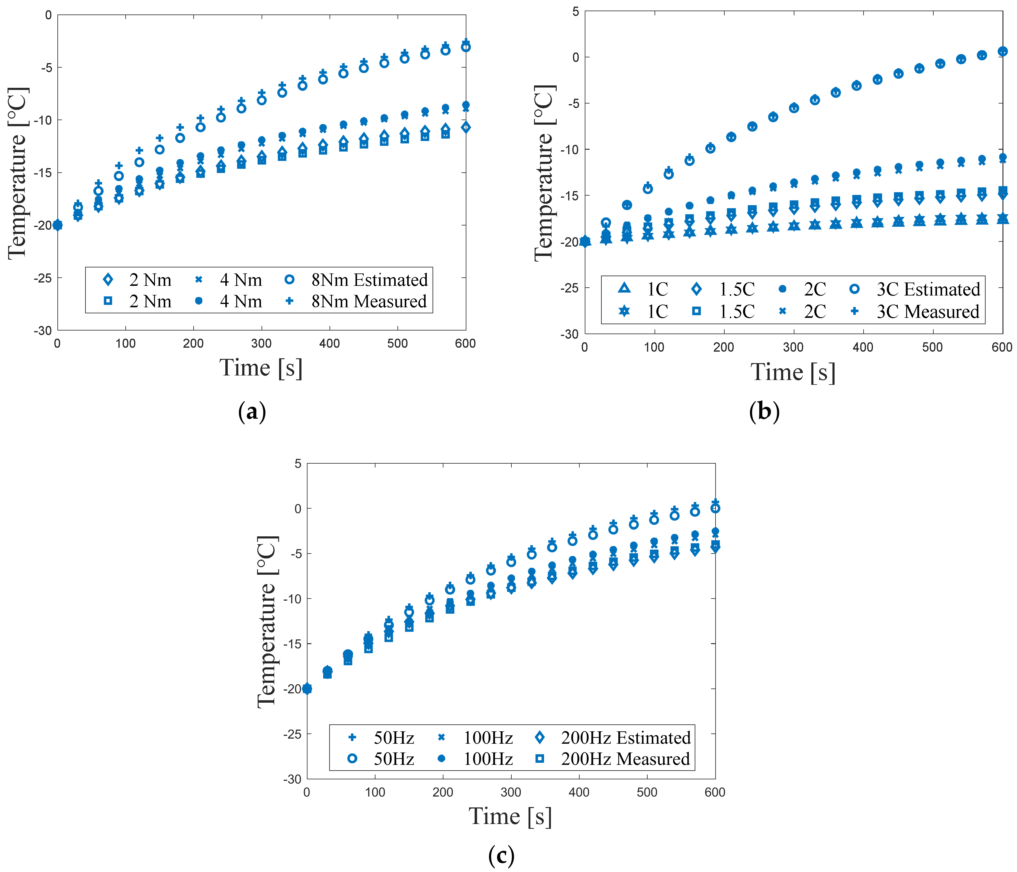
Figure 18 shows battery temperature variation under constant driving and heating conditions. The initial temperature of the battery is −20 °C and the heating process lasts 10 min for all tests. Specifically, Figure 18a illustrates the battery temperature rise corresponding to the driving torques of 2 Nm, 4 Nm, and 8 Nm, respectively. An increase in driving torque leads to a higher current output from the battery, which in turn elevates the heat generation and accelerates the temperature rise. The battery thermal model can accurately predict the temperature evolution of the battery under different torque levels, with RMS errors of 0.37 °C at 2 Nm, 0.33 °C at 4 Nm, and 0.75 °C at 8 Nm.
Figure 18b shows the temperature rise with different heating current amplitudes of 1 C, 1.5 C, 2 C, and 3 C. At the end of the heating process, the battery temperature reaches −17.39 °C, −14.47 °C, −11.19 °C, and 0.68 °C. The RMS errors between the temperature measured and the temperature calculated at different current amplitudes are only 0.19 °C at 1 C, 0.30 °C at 1.5 C, 0.28 °C at 2 C, and 0.25 °C at 3 C, respectively. Because the heat generation of the battery is proportional to the square of the current amplitude, the temperature at 3 C increases much faster than the others.
Figure 18c demonstrates the influence of heating current frequency on the battery temperature. At the end of the heating process, the temperature reaches 0.68 °C at 50 Hz, −2.94 °C at 100 Hz, and −4.04 °C at 200 Hz, respectively. The RMS errors between the temperature measured and the temperature calculated are 0.59 °C, 0.4 °C and 0.38 °C respectively.
The above results indicate that the battery thermal model can accurately predict the impact of current amplitude and frequency on battery temperature. A reduction in heating current frequency is associated with an increase in the real component of the battery impedance and consequently enhances the heat generation.
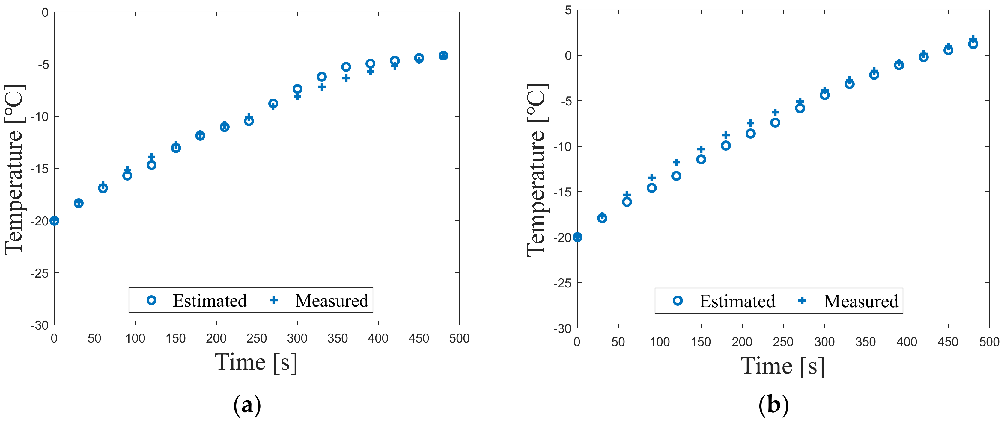
The results of the validation test for combined driving conditions are depicted in Figure 19. The RMS error for temperature prediction is 0.53 °C for the aggressive driving style and 0.82 °C for the gentle driving style. These results indicate that the battery electro-thermal model maintains a high fidelity in predicting battery temperature even for the real-world usage.

4.4. Validation of NPBH Performance in Preheating Mode

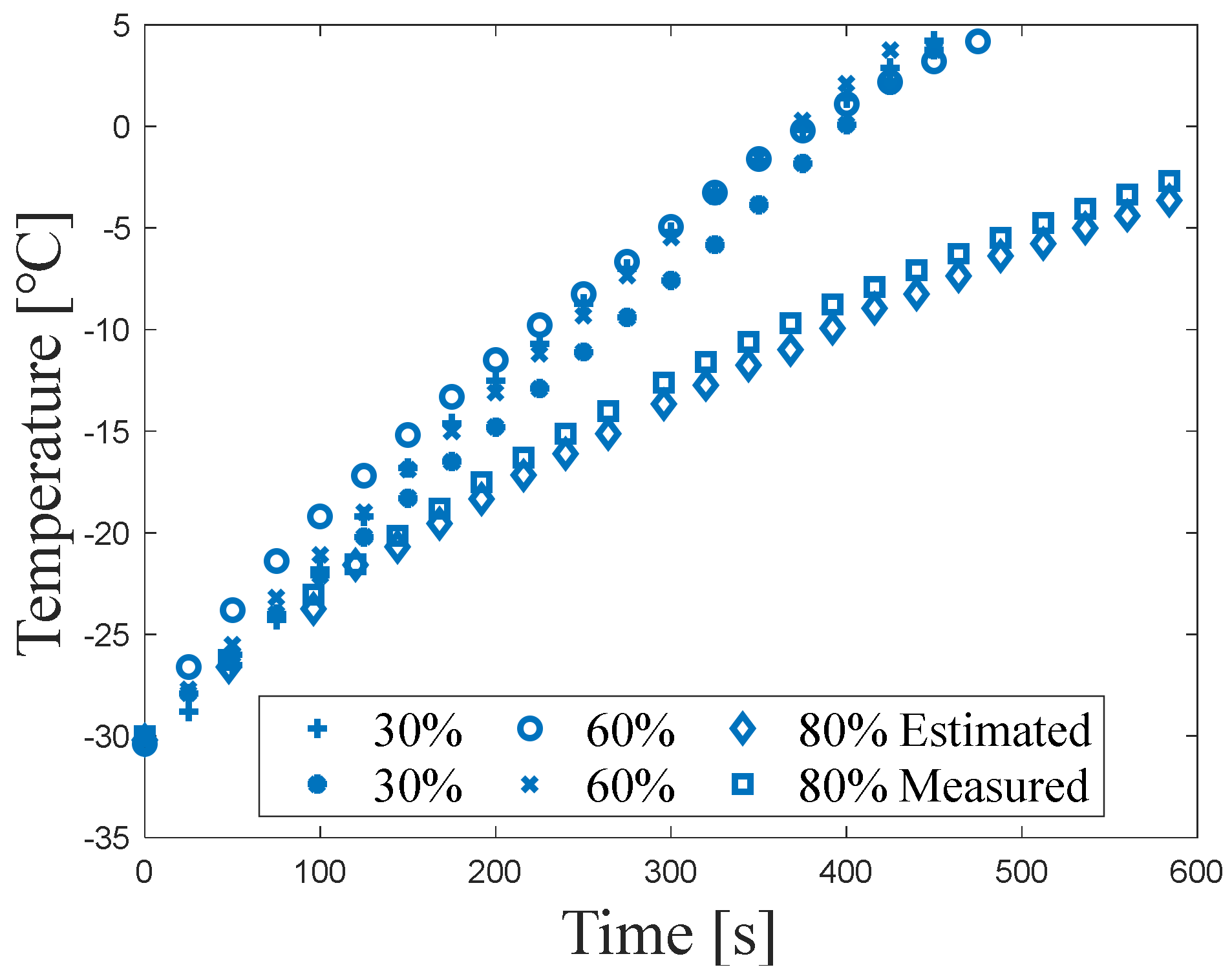
In this subsection, the preheating with optimal strategy is validated at SOC levels of 30%, 60%, and 80% with an initial temperature of −30 °C. Figure 20 represents the temperature rising processes with a current amplitude of 3.6 C. It can be seen that when the SOC level is at 30% or 60%, the temperature rise processes are quite similar. Their average RTR from −30 °C to 0 °C achieves 4.76 °C/min. However, when the battery SOC level increases to 80%, the temperature rise rate is significantly lower than the two formers. The reason is that EIS characteristics exhibit relatively minor variations within the mid-range of SOC compared to those observed at both high and low SOC. Specially, at high SOC levels, the battery OCV approaches the charging cut-off limit. Consequently, the frequency of heating current is substantially increased to reduce the impedance of the battery, ensuring the compliance with voltage constraints while maximizing the heat generation.

4.5. Comparison of Different Techniques

To demonstrate the benefits of the NPBH method, a systematic comparison of the existing technologies is presented in Table 8, evaluating heating performance, energy consumption, functional diversity, as well as complexity and cost. The NPBH demonstrates not only a high RTR but also a broader compatibility with the heating mode in comparison to alternative approaches. Furthermore, this new approach is easy to implement because it does not require specialized torque elimination control or the determination of a particular rotor stall position. Regarding the extra component required, the NPBH only adds one switch, which greatly reduces the system complexity as well as the modification cost.

5. Conclusions

This study proposes a novel battery self-heating method, known as the NPBH, which is compatible with both preheating and on-route heating, and delivers high-rate and uniform warming. It markedly reduces the complexity and cost of the battery on-board AC heater. An EDS testbench with a thermal chamber for the battery is built to validate the proposed method. The experimental results demonstrate the following:
  • The proposed NPBH technique provides efficient heating for LiBs with rapid speed.
  • The NPBH offers a simpler and more reliable approach in heating current control. The undesired electromagnetic torque caused by the heating current can be inherently eliminated regardless of the rotor position.
  • The control of heating and driving is completely decoupled, which enables the NPBH to be compatible with both preheating and on-route heating modes, while also facilitating straightforward adaptation to a range of heating strategies.
  • The proposed electro-thermal model can estimate the battery temperature with a high fidelity. The RMS errors of battery temperature under all the constant and combined driving conditions are less than 1 °C.
In summary, based on a comprehensive evaluation across distinct conditions, the NPBH demonstrates a great practical utility. A hybrid heating strategy combining preheating and on-route heating based on the NPBH method can further reduce the time consumed by heating while enhancing the battery performance on driving. In practice, inconsistencies in the switching transistor may cause unbalanced currents, leading to inverter degradation issues, which need to be paid attention. These will be the key focus of the future work in this article.

Author Contributions

Conceptualization, G.Z., L.J. and Y.Y.; Writing—original draft, G.Z.; Writing—review and editing, G.Z., L.J. and Y.Y.; Methodology, G.Z. and L.J.; Software, G.Z., L.Z. and M.Y.; Validation, G.Z.; Formal analysis, G.Z.; Funding acquisition, L.J. and Y.Y.; Investigation, G.Z. and X.Y.; Project administration, L.J. and Y.Y.; Resources, G.Z., X.Y. and Z.S.; Supervision, L.J. and Y.Y.; Visualization, G.Z.; Data curation, G.Z., X.Y. and L.Z.; Funding acquisition, L.J. and Y.Y. All authors have read and agreed to the published version of the manuscript.

Funding

This work was supported by the National Key Laboratory of Multi-perch Vehicle Driving Systems (Grant No. QDXT-NY-202407-09).

Institutional Review Board Statement

Not applicable.

Informed Consent Statement

Not applicable.

Data Availability Statement

This study has no additional data available.

Conflicts of Interest

The authors declare no conflicts of interest. The funders had no role in the design of the study; in the collection, analyses, or interpretation of the data; in the writing of the manuscript; or in the decision to publish the results.

Abbreviations

The following abbreviations are used in this manuscript:
BMSBattery Management System
BTMSBattery Thermal Management System
ECMEquivalent Circuit Model
EDSElectric Drive System
EISElectrochemical Impedance Spectroscopy
EMElectric Motor
EVElectric Vehicle
D-axisDirect Axis
DMSIDual-Module Separated Inverter
IBSHIntegrated Battery Self-Heater
LiBLithium-ion Battery
NPBHNeutral Point Battery Heater
PTCPositive Temperature Coefficient
Q-axisQuadrant Axis
RMSRoot Mean Square
RTRRate of Temperature Rise
SOHState of Health
SPWMSinusoidal Pulse Width Modulation
TMSITriple-Module Separated Inverter

References

  1. Zahid, T.; Xu, K.; Li, W.; Li, C.; Li, H. State of charge estimation for electric vehicle power battery using advanced machine learning algorithm under diversified drive cycles. Energy 2018, 162, 871–882. [Google Scholar] [CrossRef]
  2. Li, J.; Fang, L.; Shi, W.; Jin, X. Layered thermal model with sinusoidal alternate current for cylindrical lithium-ion battery at low temperature. Energy 2018, 148, 247–257. [Google Scholar] [CrossRef]
  3. Hu, M.; Li, Y.; Li, S.; Fu, C.; Qin, D.; Li, Z. Lithium-ion battery modeling and parameter identification based on fractional theory. Energy 2018, 165, 153–163. [Google Scholar] [CrossRef]
  4. Christensen, G.; Younes, H.; Hong, H.; Widener, C.; Hrabe, R.H.; Wu, J. Nanofluids as media for high capacity anodes of lithium-ion battery—A review. J. Nanofluids 2019, 8, 657–670. [Google Scholar] [CrossRef]
  5. Chen, Y.; Zhu, M.; Chen, M. Comprehensive experimental research on wrapping materials influences on the thermal runaway of lithium-ion batteries. Emerg. Manag. Sci. Technol. 2025, 5, e007. [Google Scholar] [CrossRef]
  6. Zhang, J.; Long, T.; Sun, X.; He, L.; Yang, J.; Wang, J.; Wang, Z.; Huang, Y.; Zhang, L.; Zhang, Y. Mechanism investigation on microstructure degradation and thermal runaway propagation of batteries undergoing high-rate cycling process. J. Energy Chem. 2026, 113, 1013–1029. [Google Scholar] [CrossRef]
  7. Jia, Y.; Yue, Y.; Xu, W.; Wang, C.; Huang, Y.; Wang, Z.; Wang, J.; Lu, Y. Thermal runaway features of prismatic NCM battery undergone high-rate charging/discharging: Mechanism investigation and safety evaluation. J. Energy Storage 2025, 115, 115226. [Google Scholar] [CrossRef]
  8. Jia, Y.; Zhang, J.; Yang, J.; Cai, W.; Lu, Y.; Wang, Z.; Wang, J.; Huo, S. Unveiling binary transition metal selenides with carbon aerogel veil for superior and safe lithium ion/sodium ion battery. J. Energy Storage 2025, 120, 116506. [Google Scholar] [CrossRef]
  9. Wang, J.; Yue, Y.; Yu, K.; Han, C.; Yang, J.; Zhang, L.; Zhang, Y.; Wang, Z.; Huang, Y. Thermal runaway behaviors of lithium iron phosphate battery with various capacity and state of charge: Characteristic comparison and safety assessment. Appl. Therm. Eng. 2026, 284, 129170. [Google Scholar] [CrossRef]
  10. Wang, J.; Li, L.; Yu, K.; Zhang, J.; Huang, Y.; Wang, Z.; Wang, W.; Zhao, T.; Huo, S. Comprehensive investigation on the water mist inhibition efficacy towards battery thermal runaway and its smoke hazard via regulating the releasing settings. Process Saf. Environ. Prot. 2025, 204, 108001. [Google Scholar] [CrossRef]
  11. Wang, J.; Huang, Y.; Wang, C.; Ruan, Y.; Xu, W.; Li, K.; Wang, Z.; Zhang, L.; Zhang, Y.; Lu, Y. Thermal runaway and jet fire features of battery modules endured high-rate cycling in confined space: Mechanism investigation and safety assessment. Appl. Therm. Eng. 2025, 279, 127657. [Google Scholar] [CrossRef]
  12. Jiang, J.; Ruan, H.; Sun, B.; Wang, L.; Gao, W.; Zhang, W. A low-temperature internal heating strategy without lifetime reduction for large-size automotive lithium-ion battery pack. Appl. Energy 2018, 230, 257–266. [Google Scholar] [CrossRef]
  13. Kvasha, A.; Gutierrez, C.; Osa, U.; Meatza, I.; Blazquez, J.; Macicior, H.; Urdampilleta, I. A comparative study of thermal runaway of commercial lithium ion cells. Energy 2018, 159, 547–557. [Google Scholar] [CrossRef]
  14. Wu, S.; Xiong, R.; Li, H.; Nian, V.; Ma, S. The state of the art on preheating lithium-ion batteries in cold weather. J. Energy Storage 2020, 27, 101059. [Google Scholar] [CrossRef]
  15. Peng, X.; Chen, S.; Garg, A.; Bao, N.; Panda, B. A review of the estimation and heating methods for lithium-ion battery pack at the cold environment. Energy Sci. Eng. 2019, 7, 645–662. [Google Scholar] [CrossRef]
  16. Zhu, C.; Du, L.; Guo, B.; Fan, G.; Lu, F.; Zhang, H.; Liu, K.; Zhang, X. Internal heating techniques for lithium-ion batteries at cold climates: An overview for automotive applications. IEEE Trans. Transp. Electrif. 2022, 9, 5012–5027. [Google Scholar] [CrossRef]
  17. Wang, C.Y.; Zhang, G.; Ge, S.; Xu, T.; Yang, X.G.; Leng, Y. Lithium-ion battery structure that self-heats at low temperatures. Nature 2016, 529, 515–518. [Google Scholar] [CrossRef]
  18. Zhang, G.; Ge, S.; Xu, T.; Yang, X.; Tian, H.; Wang, C. Rapid self-heating and internal temperature sensing of lithium-ion batteries at low temperatures. Electrochim. Acta 2016, 218, 149–155. [Google Scholar] [CrossRef]
  19. Yang, X.G.; Zhang, G.; Wang, C.Y. Computational design and refinement of self-heating lithium ion batteries. J. Power Sources 2016, 328, 203–211. [Google Scholar] [CrossRef]
  20. Li, J.; Xue, Q.; Gao, Z.; Liu, Z.; Xiao, Y. Frequency varying heating strategy for lithium-ion battery rapid preheating under subzero temperature considering the limitation of on-board current. Appl. Energy 2024, 365, 123183. [Google Scholar] [CrossRef]
  21. Huang, X.; Meng, J.; Jiang, W.; Liu, W.; Liu, K.; Zhang, Y.; Stroe, D.; Teodorescu, R. Alternating current heating techniques for lithium-ion batteries in electric vehicles: Recent advances and perspectives. J. Energy Chem. 2024, 96, 679–697. [Google Scholar] [CrossRef]
  22. Shang, Y.; Xia, B.; Cui, N.; Zhang, C.; Mi, C. An automotive onboard AC heater without external power supplies for lithium-ion batteries at low temperatures. IEEE Trans. Power Electron. 2018, 33, 7759–7769. [Google Scholar] [CrossRef]
  23. Shang, Y.; Liu, K.; Cui, N.; Wang, N.; Li, K.; Zhang, C. A compact resonant switched-capacitor heater for lithium-ion battery self-heating at low temperatures. IEEE Trans. Power Electron. 2020, 35, 7134–7144. [Google Scholar] [CrossRef]
  24. Shang, Y.; Liu, K.; Cui, N.; Zhang, Q.; Zhang, Q. A sine-wave heating circuit for automotive battery self-heating at subzero temperatures. IEEE Trans. Ind. Inform. 2020, 16, 3355–3365. [Google Scholar] [CrossRef]
  25. Hu, Z.; Li, Y.; Liu, F.; Zhao, B.; Li, W.; Yang, R.; Xie, C.; Shi, Y. Thermal characteristics investigation of lithium-ion battery under high-frequency AC excitation in low-temperature environment. IEEE Trans. Transp. Electrif. 2022, 8, 407–419. [Google Scholar] [CrossRef]
  26. Shang, Y.; Zhu, C.; Fu, Y.; Mi, C. An integrated heater equalizer for lithium-ion batteries of electric vehicles. IEEE Trans. Ind. Electron. 2019, 66, 4398–4405. [Google Scholar] [CrossRef]
  27. Uno, M.; Sugaya, R.; Sasama, Y. Selective module-to-cell equalizer with internal AC heating capability for automotive lithium-ion batteries at subzero temperatures. IEEE J. Emerg. Sel. Top. Power Electron. 2023, 11, 5430–5440. [Google Scholar] [CrossRef]
  28. Du, C.; Peng, Q.; Chen, F.; Deng, K.; Chen, J.; Deng, C.; Hu, M. Investigation on the method of battery self-heating using motor pulse current. Proc. Inst. Mech. Eng. Part D J. Automob. Eng. 2022, 236, 2399–2409. [Google Scholar] [CrossRef]
  29. Li, Y.; Gao, X.; Qin, Y.; Du; Guo, J.; Feng, D.; Ouyang, X.; Ouyang, M. Drive circuitry of an electric vehicle enabling rapid heating of the battery pack at low temperatures. iScience 2021, 24, 101997. [Google Scholar] [CrossRef]
  30. Li, Y.; Du, J.; Zhou, G.; Ouyang, M.; Fan, Y. A rapid self-heating battery pack achieved by novel driving circuits of electric vehicle. Energy Rep. 2020, 6, 1016–1023. [Google Scholar] [CrossRef]
  31. Zhu, C.; Han, J.; Zhang, H.; Lu, F.; Liu, K.; Zhang, X. Modeling and control of an integrated self-heater for automotive batteries based on traction motor drive reconfiguration. IEEE J. Emerg. Sel. Top. Power Electron. 2023, 11, 384–395. [Google Scholar] [CrossRef]
  32. Liu, Z.; Liu, F.; Lu, S.; Xie, C. Amplitude-frequency decoupled heater and integrated strategies for automotive batteries based on inverter and motor. IEEE Trans. Power Electron. 2023, 39, 1565–1576. [Google Scholar] [CrossRef]
  33. Gao, Z.; Li, J.; Yang, Y.; Xue, Q.; Liu, Z.; Xiao, Y. Integrated drive circuit-based sinusoidal current self-heating method and optimization for Li-ion batteries. Appl. Therm. Eng. 2025, 279, 128054. [Google Scholar] [CrossRef]
Figure 1. Categorization of the battery heating methods and the current excitation EV implementations.
Sustainability 18 02998 g001
Figure 2. Circuit topology of NPBH.
Sustainability 18 02998 g002
Figure 3. Four stages of one operating cycle.
Sustainability 18 02998 g003
Figure 4. Relationship of PWM signals, heating current i0, and torque Tem.
Sustainability 18 02998 g004
Figure 5. The current waveform of EM windings and battery modules.
Sustainability 18 02998 g005
Figure 6. The control logic diagram.
Sustainability 18 02998 g006
Figure 7. Second-order ECM of the battery.
Sustainability 18 02998 g007
Figure 8. Test bench of EDS integrated with NPBH.
Sustainability 18 02998 g008
Figure 9. Batteries under test. (a) Prismatic; (b) cylindrical.
Sustainability 18 02998 g009
Figure 10. Category of validation testing.
Sustainability 18 02998 g010
Figure 11. Current waveforms from oscilloscope (ω = 0 rpm, Tem = 0 Nm, Iheat = 3 C, f = 100 Hz).
Sustainability 18 02998 g011
Figure 12. Torque fluctuation. (a) Influence of current amplitudes (f = 100 Hz, θ = 0°); (b) influence of rotor positions (Iheat = 1.5 C, f = 100 Hz).
Sustainability 18 02998 g012
Figure 13. Current waveforms from oscilloscope (ω = 100 rpm, Tem = 6 Nm, Iheat = 1.5 C, f = 50 Hz).
Sustainability 18 02998 g013
Figure 14. Validation for the decoupling control of the driving and the heating. (a) Variation in rotor speed n (Tem = 2 Nm, Iheat = 1.5 C, f = 50 Hz); (b) variation in torque Tem (n = 100 rpm, Iheat = 4 A, f = 50 Hz); (c) Variation in heating current amplitude Iheat (n = 100 rpm, Tem = 4 Nm, f = 50 Hz); (d) variation in heating current frequency f (n = 100 rpm, Tem = 4 Nm, Iheat = 1.5 C).
Sustainability 18 02998 g014
Figure 15. Simulation model of on-route heating scenario.
Sustainability 18 02998 g015
Figure 16. Speed and torque profile of the first 10 min of WLTC driving cycle. (a) Speed; (b) torque.
Sustainability 18 02998 g016
Figure 17. Heating current waveform of the first 10 min of WLTC driving cycle. (a) Panorama view; (b) zoom in view at the moment of 300 s.
Sustainability 18 02998 g017
Figure 18. Validation for the modeling approach of battery electro-thermal characteristics under constant driving and heating conditions. (a) Variation in torque Tem (n = 100 rpm, Iheat = 2 C, f = 50 Hz); (b) variation in heating current amplitude Iheat (n = 100 rpm, Tem = 2 Nm, f = 50 Hz); (c) variation in heating current frequency f (n = 100 rpm, Tem = 2 Nm, Iheat = 3 C).
Sustainability 18 02998 g018
Figure 19. Battery temperature evolution under combined driving profiles. (a) Aggressive driving style. (b) Gentle driving style.
Sustainability 18 02998 g019
Figure 20. Temperature rises with different SOCs (Iheat = 3.6 C).
Sustainability 18 02998 g020
Table 1. Parameters of EM.
ParametersValueUnit
TypeSurface mounted PMSM-
Number of pole pairs4-
Stator inductance3.21mH
Phase resistance1.38Ω
Permanent flux linkage0.1667Wb
Rated current10A
Rated power1kW
Table 2. Parameters of batteries.
ParametersPrismaticCylindricalUnit
Electrode materialNMC-CNMC-C-
Nominal capacity584Ah
Charge cut-off voltage4.254.2V
Discharge cut-off voltage2.22.5V
Geometric dimensionsWidth: 149
Height: 93
Thickness: 27
Diameter: 21
Height: 70
-
mm
Density23332763.4kg/m3
Specific heat900910J/kg/K
Thermal conductivity37.436W/m/K
Table 3. Experimental design of heating torque elimination.
Rotor Angle
[°]
Iheat
[C]
f
[Hz]
00.75/1.5/3100
0/7.5/15/22.5/301.5100
Table 4. Experimental design of current decoupling control.
n
[rpm]
Tem
[Nm]
Iheat
[C]
f
[Hz]
100/150/20021.550
1000/3/61.550
10040/1.125/2.2550
10041.510/30/50
Table 5. Experimental design of on-route heating under constant conditions.
n
[rpm]
Tem
[Nm]
Iheat
[C]
f
[Hz]
1002/4/8250
10021/1.5/2/350
1002350/100/200
Table 6. Experimental design of on-route heating with combined driving conditions.
Driving StyleStageDuration
[min]
n
[rpm]
Tem
[Nm]
Iheat
[C]
f
[Hz]
Aggressive1210081.550
222006250
323004350
4230043200
Gentle1110043200
2120043200
3230023.6200
4230023.6100
5230023.650
Table 7. Control parameters of preheating under optimal strategy.
Tb
[℃]
Iheat
(30% SOC)
[C]
f
(30% SOC)
[Hz]
Iheat
(60% SOC)
[C]
f
(60% SOC)
[Hz]
Iheat
(80% SOC)
[C]
f
(80% SOC)
[Hz]
−303.60373.60752.35623
−253.60223.60452.83584
−203.54153.60282.88509
−153.51113.60203.17506
−103.6083.56143.29433
−53.5463.5493.57400
03.5623.5433.60303
Table 8. Comparison of existing technologies.
MethodRTR
[°C/min]
Energy Consumption
[%/°C]
Torque Elimination
Method
On-Route HeatingExtra ComponentsCost
Conventional Drive Circuit with Pulse Current [28]2.88-Set Iq = 0 SupportNoneLow
On-Board AC Heater [22] 3.390.25No needNot supportAt least 1 switch per module and extra inductorsHigh
TMSI [30]8.6-Set Iq = 0 Not support2 switchesHigh
IBSH [31]3.450.201Rotor position θ = kπ (k = 0, 1, 2, …)Not support1 or 2 switchesMedium
NPBH [33]4.760.2No needSupport1 switchMedium
Disclaimer/Publisher’s Note: The statements, opinions and data contained in all publications are solely those of the individual author(s) and contributor(s) and not of MDPI and/or the editor(s). MDPI and/or the editor(s) disclaim responsibility for any injury to people or property resulting from any ideas, methods, instructions or products referred to in the content.