Article

Innovative Protocol for Catalytic Hydrodehalogenation of Chlorobenzene and Bromobenzene for WEEE Cycle Closure


by
Bianca Maria Falco
1,
Milvia Elena Di Clemente
1,*,
Francesco Todaro
1,
Maria Michela Dell’Anna
1,
Paolo Francesco Garofoli
2 and
Michele Notarnicola
1
1
Department of Civil, Environmental, Land, Building Engineering and Chemistry (DICATECh), Polytechnic University of Bari, Via Edoardo Orabona n. 4, 70125 Bari, Italy
2
Department of Environmental, Landscape and Urban Quality, Apulia Region, Via Gentile n. 52, 70100 Bari, Italy
*
Author to whom correspondence should be addressed.
Sustainability 2026, 18(5), 2485; https://doi.org/10.3390/su18052485
Submission received: 5 February 2026 / Revised: 24 February 2026 / Accepted: 2 March 2026 / Published: 4 March 2026
(This article belongs to the Topic Advances and Innovations in Waste Management)

Abstract

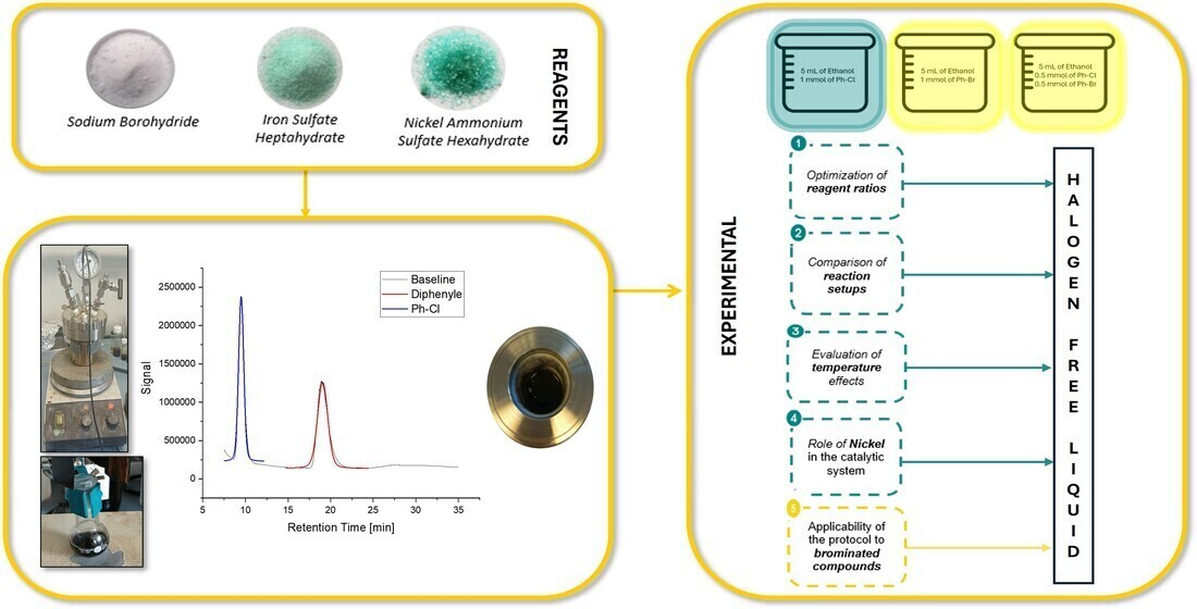
Pyrolysis of plastic from waste electrical and electronic equipment (WEEE) is a promising method for producing value-added chemicals. However, flame retardants in WEEE can cause halogen contamination in pyrolysis oil, reducing its value. This work aims to develop an innovative catalytic hydrodehalogenation (CHD) protocol for the removal of chlorobenzene and bromobenzene. Iron sulphate heptahydrate (FeSO4·7H2O) and nickel ammonium sulphate hexahydrate ((NH4)2Ni(SO4)2·6H2O) were used as catalysts, while sodium borohydride (NaBH4) acted as a hydrogen donor for iron reduction. The novelty of the process lies in the generation of nano zero-valent iron (nZVI) that takes place within the CHD reactor (in situ) without the addition of strong acids. Various experimental set-ups were investigated to optimise the key process parameters (e.g., reagent concentrations). The optimal conditions—obtained in the autoclave at 30 °C with a 1:1 molar ratio of chlorobenzene to catalyst, omission of nickel salt, and 5 mmol of NaBH4—resulted in a 75% reduction in chlorobenzene and complete removal of bromobenzene. The results confirm the effectiveness of the proposed protocol for the dehalogenation of chlorobenzene and bromobenzene, which can facilitate the valorization of pyrolysis oils derived from plastic waste, contributing to the closure of the WEEE cycle (the widest and fastest-growing source of global waste with significant environmental, social and economic impacts).

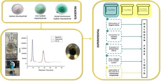
Graphical Abstract

1. Introduction

The continuous growth in global waste generation represents one of the most critical environmental and technological challenges, driving the need for advanced waste treatment technologies [1]. Pyrolysis is among the most extensively studied approaches for recovering materials and energy from heterogeneous waste streams, such as plastic-rich fraction waste streams [2,3], while reducing pollutant levels [4].
Pyrolysis is a thermochemical process in which organic materials are heated in the absence of oxygen, typically at temperatures between 300 and 700 °C, resulting in their decomposition into a gaseous fraction (syngas), a liquid fraction (pyrolysis oil), and a solid residue (char). The composition and yield of these products depend on several factors, including the heating rate, feedstock characteristics, particle size, and operating temperature. These products can be further exploited as fuels, chemical feedstocks, or functional materials, thereby contributing to circular economy strategies and reducing dependence on fossil resources [5,6,7,8]. In particular, the heat required for the process can be supplied by combusting the produced pyrolytic gas, enabling energy self-sufficiency, while the pyrolysis oil can be upgraded and used as an alternative fuel—especially in the petrochemical sector—or as chemical feedstock [9,10].
Among plastic-rich waste streams, waste from electrical and electronic equipment (WEEE) represents a particularly complex category. Global consumption of electrical and electronic equipment (EEE) has increased in recent decades, driven by technological progress, economic growth, and rising living standards [11]. Consequently, global WEEE generation reached 62 billion kg in 2022 and is projected to reach 82 billion kg by 2030. In Europe alone, 13 million tons of WEEE were generated (17.6 kg per capita), and, despite being a leader in collecting and recycling (42.8%), Europe remains below its targets [12,13]. Nowadays, the full mechanical recycling of WEEE plastics remains largely unexploited. This fraction is often discarded due to the high complexity of plastic mixtures and the limitations of current sorting technologies [14].
WEEE contains both valuable recoverable materials—such as metals, plastics, glass, precious metals, and rare earth elements [15]—and hazardous substances, including mercury, chlorofluorocarbons (CFCs), ozone-depleting compounds, and brominated flame retardants (BFRs), which are used to prevent or slow down the ignition and propagation of fires. WEEE plastics contain a wide range of impurities and fillers in addition to the polymeric matrix. These additives include hazardous substances, such as brominated and chlorinated flame retardants, plasticizers, and dyes. These substances pose significant environmental and health risks, and their presence also increases the complexity of WEEE treatment processes, often resulting in landfilling [16,17,18,19,20].
For the reasons outlined above, pyrolysis appears to be a promising solution for the treatment of complex plastic waste streams characterized by high heterogeneity and a significant presence of hazardous substances [14].
The liquid fraction is often the main target in the pyrolysis of WEEE plastics. However, the presence of polyvinyl chloride (PVC) or BFRs can introduce halogenated compounds into the pyrolysis oil [21,22]. These halogenated contaminants must be removed through dehalogenation to obtain halogen-free products suitable for further applications (e.g., fuels or chemical feedstocks) [23,24,25].
Dehalogenation of pyrolysis oils can be performed before, during or after the pyrolysis process [26]. Although the available literature remains relatively limited, post-pyrolysis strategies—such as fractional distillation or catalytic hydrodehalogenation—have shown potential, with the latter proving particularly effective in removing halogens from liquid products [27]. Catalytic hydrodehalogenation involves the reaction of pyrolysis oils with hydrogen-donating media and catalysts, producing hydrogenated liquids and valuable halides [23]. Previous studies, such as those conducted by Wu et al. [28], have demonstrated the feasibility of catalytic hydrodechlorination (HDC) of chlorobenzene in the liquid phase using sodium hydroxide (NaOH) and nickel-based catalysts (i.e., Ni/AC, Ni/γ-Al2O3 and Nickel Raney). Vasile et al. [29] evaluated the effectiveness of two commercial catalysts (DHC-8 and NiMo/AC), while Balda & Kopinke [30] investigated the role of trace nickel in enhancing HDC efficiency when catalysed by zero-valent iron (Fe0), which is commonly applied in the decontamination of organochlorine compounds.
Among recently studied catalysts, Zero-Valent Iron (ZVI) has attracted growing attention due to its natural abundance, low toxicity, and low cost. These features make it a highly promising candidate for sustainable catalytic systems. Moreover, ZVI’s strong capacity has been widely documented, confirming its suitability for hydrodechlorination [31,32,33]. Additionally, ZVI has been reported to hydrodechlorinate halogenated compounds directly in its zero-valent state has also been reported [30].
Although several dehalogenation strategies have been explored in the literature, recent contributions remain limited in scope, often outdated, or lacking comprehensive experimental validation [34]. This highlights the need for further development of more practical and efficient dehalogenation protocols.
In this study, we address the challenge of removing halogenated contaminants (chlorine and bromine species) commonly found in plastic-derived pyrolysis oils. In particular, we propose catalytic hydrodehalogenation (CHD) as a promising liquid-phase method for selective halogen removal.
In order to isolate and investigate the fundamental reaction pathways and catalytic performance, the proposed approach was evaluated using a model solution of ethanol containing representative halogenated compounds, like WEEE pyrolysis oil.
The CHD process involves the cleavage of C-Cl and C-Br bonds in the presence of a hydrogen donor and suitable catalysts. The novelty of this work lies in the in situ generation of nano zero-valent iron (nZVI, Fe0) directly in the dehalogenation reactor. The nZVI is produced from iron(II) sulfate heptahydrate (FeSO4·7H2O) and hydrogen gas, using sodium borohydride (NaBH4) as reducing agent for both iron(II) salt and Ar-X compounds. This approach avoids the subsequent addition of a strong acid, as usually reported in many works [35,36,37]. This reductive activation step allows for the formation of active Fe0 species in parallel with the hydrodehalogenation reaction.

2. Materials and Methods

2.1. Experimental Plan

To evaluate the effectiveness of the dehalogenation process under controlled and reproducible conditions, experimental tests were conducted in reactors with magnetic stirring for 3 h at the desired temperature. NaBH4 was used as the hydrogen donor reagent in the appropriate amount, while FeSO4·7H2O was selected as the catalyst, in the presence and in the absence of (NH4)2Ni(SO4)2·6H2O.
The catalytic hydrodehalogenation (CHD) protocol was evaluated in a controlled liquid-phase system using model halogenated compounds. Three types of ethanol solutions were prepared:
  • Chlorobenzene (Ph-Cl), 1 mmol;
  • Bromobenzene (Ph-Br), 1 mmol;
  • mixed solution containing 0.5 mmol of Ph-Cl and 0.5 mmol of Ph-Br.
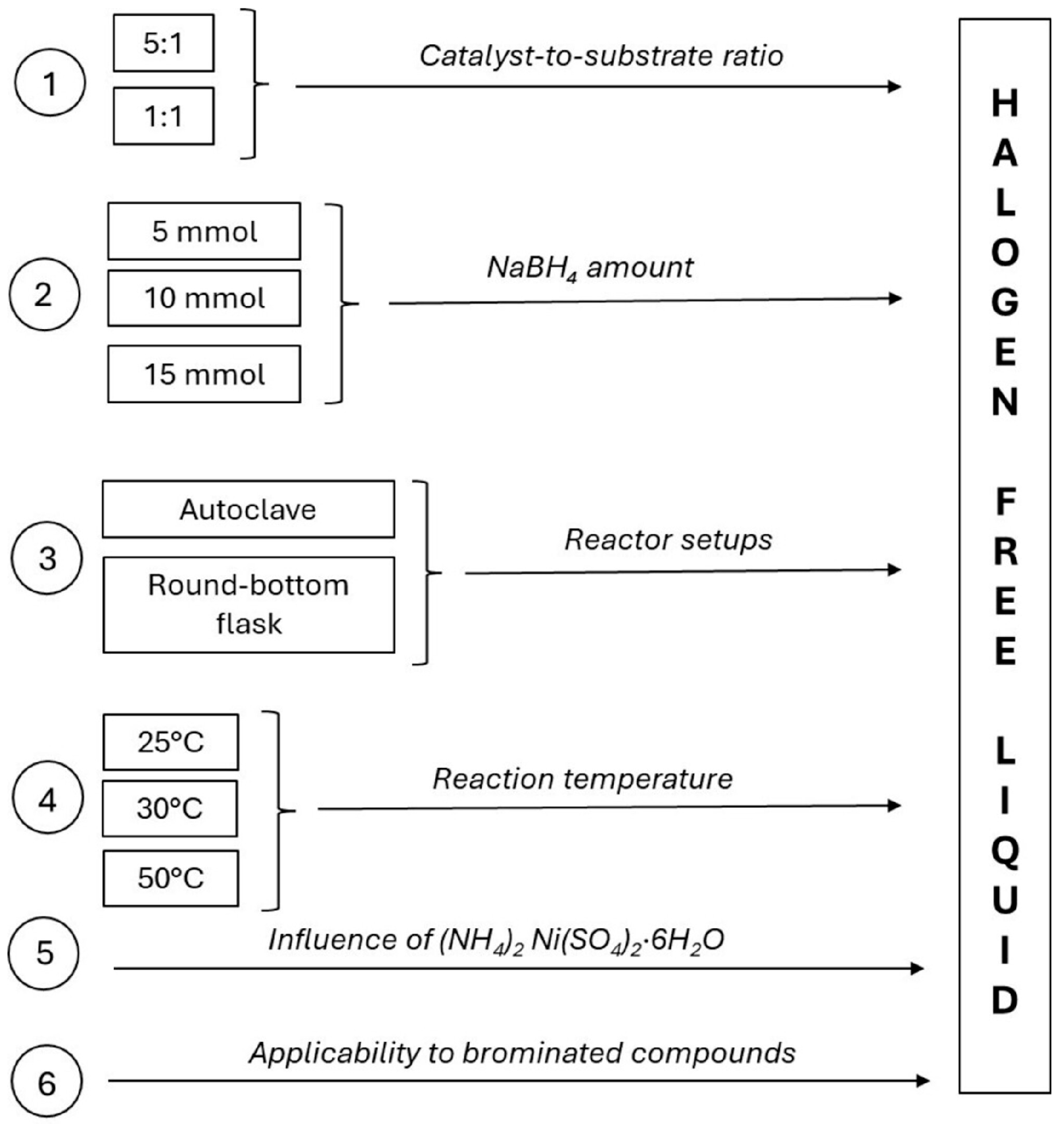
To ensure a systematic evaluation of the process, the experimental plan was divided into six main phases (Figure 1). Initial experiments were performed in a stainless-steel autoclave at room temperature (~25 °C), employing a molar ratio of halogenated substrate to FeSO4·7H2O of 1:5 (1 mmol Ph-Cl, 5 mmol FeSO4·7H2O). (NH4)2Ni(SO4)2·6H2O was introduced as a co-catalyst, and NaBH4 (15 mmol) was added as the reducing and hydrogen-donating agent. These first trials were deliberately carried out under excess reagent conditions to maximize catalytic activation and halogen removal. Subsequently, for environmental and economic reasons, the molar ratio was reduced to 1:1 (1 mmol Ph-Cl, 1 mmol FeSO4·7H2O), allowing the evaluation of process efficiency under more sustainable conditions.
In the second phase, the influence of the reducing agent dosage was investigated by varying the amount of NaBH4 (5, 10, and 15 mmol) while keeping the catalyst-to-substrate ratio constant, in order to assess the minimum amount required to achieve effective dehalogenation.
The third phase focused on the role of the reactor configuration by comparing experiments performed in a stainless-steel autoclave and in a round-bottom flask, thereby evaluating the effect of pressure control and hydrogen retention on reaction performance.
In the fourth phase, the effect of temperature was examined under controlled conditions by conducting experiments at 25, 30, and 50 °C, with the aim of identifying optimal thermal conditions and assessing the temperature sensitivity of the process.
The fifth phase evaluated the influence of nickel by performing selected experiments in the absence of (NH4)2Ni(SO4)2·6H2O, in order to clarify its role and verify potential synergistic or inhibitory effects within the catalytic system.
Finally, in the sixth phase, the applicability of the optimized protocol to brominated compounds was assessed by replacing chlorobenzene with bromobenzene and by testing mixed halogenated systems, thus evaluating the robustness and versatility of the process toward different halogenated substrates.
Figure 1. Experimental design.
Sustainability 18 02485 g001

2.2. Materials

All chemicals were purchased from Sigma Aldrich (Burlington, MA, USA) and used without further purification: chlorobenzene (C6H5Cl), bromobenzene (C6H5Br), ethanol (96% v/v, C2H6O), sodium borohydride (NaBH4), iron(II) sulphate heptahydrate (FeSO4·7H2O), and nickel ammonium sulphate hexahydrate [(NH4)2Ni(SO4)2·6H2O].

2.3. Catalytic Hydrodehalogenation Test

In the CHD test, a 50 mL reactor (i.e., stainless-steel autoclave or round-bottom flask) was filled with FeSO4·7H2O (5 or 1 mmol) and possibly with (NH4)2Ni(SO4)2·6H2O (1 or 0.2 mmol). Afterwards, NaBH4 was added in the appropriate amount (5, 10, or 15 mmol). A solution of Ph-Cl or Ph-Br (1 mmol) in 5 mL of ethanol was prepared and then added to the reactor containing the salts. Then, the reactor was closed and left under magnetic stirring for 3 h at the desired temperature. At the end of the reaction, the mixture was cooled to room temperature and then the valve was opened to release the produced hydrogen gas. Diphenyl (50 mg) was added as the internal standard. The solution thus obtained was removed from the solid phase and analyzed using a GC-FID instrument.
The identification of the most appropriate catalyst-to-substrate ratio was a crucial step in optimizing the dehalogenation system. The protocol was adapted to the present experimental objectives, using the work of Balda & Kopinke [30] as a starting point. Compared with their work, the catalyst loading was reduced by a factor of ten; however, the resulting molar ratio remains relatively high.
The catalytic hydrodehalogenation (CHD) mechanism can be conceptually divided into two main stages:
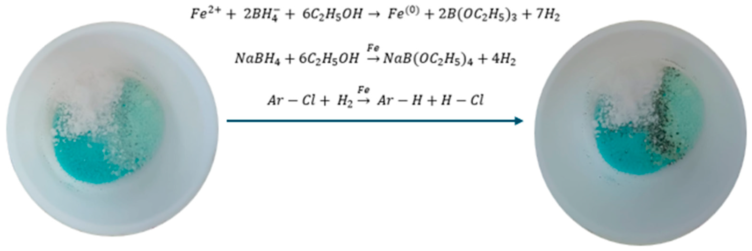
  • Fe2+ ions from FeSO4·7H2O reacts with NaBH4 in ethanol, producing Fe0 (nZVI), B(OC2H5)3 and molecular hydrogen (H2), as shown in Equation (1). This step supplies the necessary hydrogen for hydrodehalogenation and creates a reductive environment.
  • Once generated, Fe0 serves as an electron donor, promoting the formation of further hydrogen gas (Equation (2)) and the reduction of halogenated compounds (Ar-Cl) into their corresponding hydrocarbons (Ar-H) (Equation (3)). Simultaneously, the high concentration of molecular hydrogen in the system promotes the formation of hydrogen chloride (HCl) in the gas phase (Equation (3)).
The overall reaction pathway can be summarized as follows (Figure 2):
F e 2 + +   2 B H 4 +   6 C 2 H 5 O H   F e ( 0 ) + 2 B ( O C 2 H 5 ) 3 + 7 H 2
N a B H 4 + 6 C 2 H 5 O H   F e N a B ( O C 2 H 5 ) 4 + 4 H 2
A r C l + H 2 F e   A r H + H C l

2.4. Methods

2.4.1. Chromatography Analysis

The performance of the catalytic system was evaluated by calculating the percentage conversion (Conv%) of Ph-Cl and Ph-Br into non-halogenated compounds. The samples were analysed by gas chromatography with flame ionisation detection (GC-FID), using an HP 6890 instrument equipped with a Supelcowax-10 capillary column (90.0 m × 0.250 mm × 1.0 µm) (MilliporeSigma, Burlington, MA, USA).
To obtain accurate quantitative data, an internal standard (biphenyl) was used, and calibration curves were created using four standard solutions with known concentrations.
The GC–FID analysis took 35 min per sample. After each analysis, spectrum reflecting the sample composition was obtained. The compounds in each sample were separated chromatographically and identified and quantified based on their specific retention times. The retention times of the analysed compounds were as follows: chlorobenzene (9.49 min), bromobenzene (14.27 min) and biphenyl (18.27 min).
Four standard solutions at known concentrations were prepared in order to construct a calibration curve. The peak areas were then plotted against the corresponding masses on the x-axis and a linear regression model was applied to obtain the calibration equation. This equation was then used to determine the concentrations of the target compounds in the reaction samples.
Specifically, four standard solutions of chlorobenzene (at concentrations of 1, 0.8, 0.4 and 0.2 mmol) were prepared using ethanol as the solvent, with the addition of 0.05 g of biphenyl as the internal standard. The resulting chromatograms were processed to construct the chlorobenzene calibration curve via linear regression. The same procedure was followed to obtain the bromobenzene calibration curve for tests 13 and 14.
Ultimately, the GC analysis was used to determine the final amount of chlorobenzene in the reaction mixtures. This made it possible to calculate the percentage conversion of chlorobenzene (and, by analogy, bromobenzene) using the following equation:
C o n v % =   ( P h C l ) i   ( P h C l ) f   ( P h C l ) i × 100
More information is reported in the Supplementary Materials.

2.4.2. SEM Analysis

nZVI morphological characterization were carried out on a field emission gun scanning electron microscope (FEG-SEM) Zeiss Σigma 300 VP (Zeiss, Oberkochen, Germany). The samples were deposited on aluminum stubs coated with a pure graphite tape and sputtered with gold with a Sputter Quorum Q150 (Quorum Technologies Ltd., East Sussex, UK). Analyses were performed at 0.5 ÷ 30 kV using a 7.5 mm working distance at a 1000× magnification.

3. Results and Discussion

This section presents the experimental results of the catalytic hydrodehalogenation tests, with Table 1 summarizing the investigated operating conditions and the corresponding chlorine conversion efficiencies, expressed as the percentage of chloride ions converted into hydrochloric acid.
Table 2 shows the initial and final halogen contents measured for each hydrodehalogenation experiment.

3.1. Optimization of Reaction Conditions for Chlorinated Compounds

3.1.1. Optimization of Reagent Ratios

The first experiment achieved complete dehalogenation of Ph-Cl, with 100% conversion and full sequestration of chloride ions. This resulted in the formation of gaseous hydrochloric acid (HCl). No significant temperature or pressure variations were detected throughout the reaction.
However, when applied to real-world conditions, this catalytic system offers no economic or environmental advantage because it requires reagent excess.
To address this limitation, the catalyst loading was reduced by adopting a 1:1 molar ratio of FeSO4·7H2O to Ph-Cl. Under these milder conditions, a conversion efficiency of 72% was achieved (see Test 1 in Table 1), indicating that substantial activity could be maintained even with lower reagent consumption. This balance between performance and sustainability justified the use of the 1:1 ratio in subsequent experiments.
In all cases, the molar ratio of the iron-based catalyst to the nickel-based catalyst was maintained at 5:1.

3.1.2. Assessment of NaBH4 Dosage and Reactor Setups
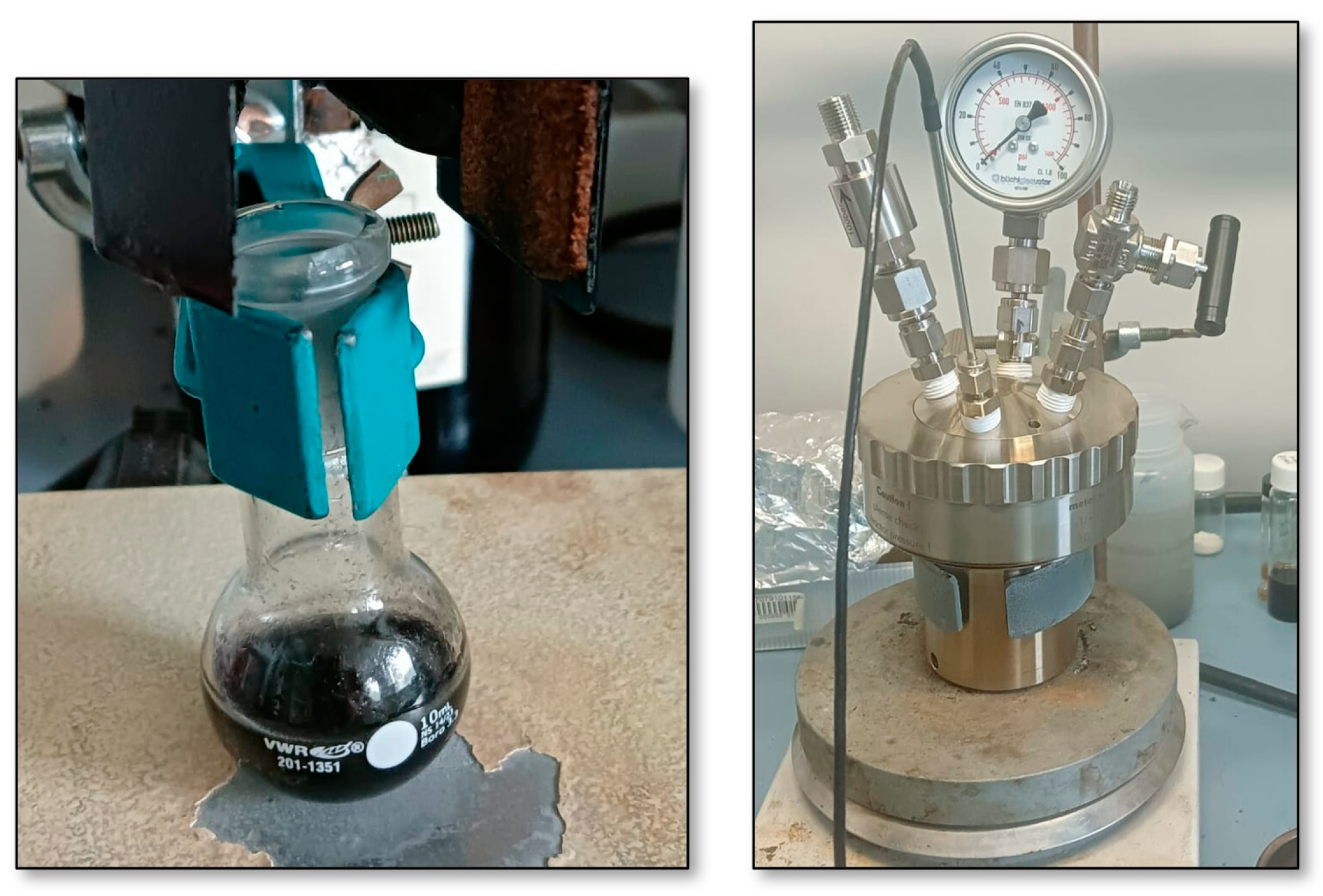
Following the optimization of catalyst loading, the effect of NaBH4 concentration in the catalytic system was further investigated. The ethanol volume and catalyst concentrations were kept constant, while the NaBH4 loading was systematically varied to assess its effect on dehalogenation efficiency. In this phase, the influence of the reaction vessel was also investigated by comparing performance in two configurations: a 50 mL stainless-steel autoclave and a standard round-bottom flask (Figure 3).
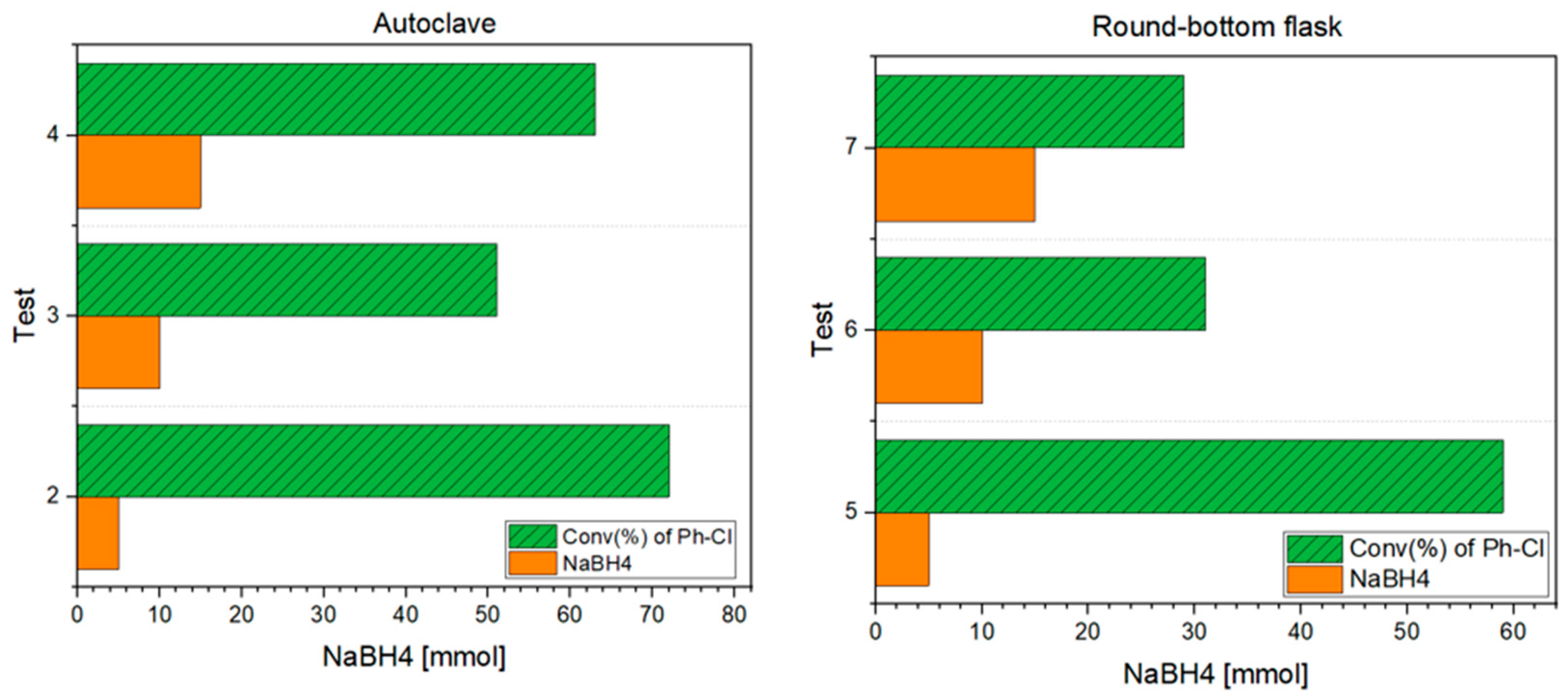
Experiments were carried out using three different doses—5 mmol, 10 mmol and 15 mmol—in both an autoclave and a round-bottom flask, to assess the influence of the reaction setup on the final rate (Figure 4).
Figure 3. Reactor setups. Left: round-bottom flask; Right: stainless-steel autoclave.
Sustainability 18 02485 g003
Figure 4. Comparison of chlorobenzene conversion efficiencies at different NaBH4 dosages (5, 10, 15 mmol) in autoclave (left) and round-bottom flask (right).
Sustainability 18 02485 g004
As shown in Figure 5, the autoclave configuration provided relatively stable conversions across NaBH4 dosages of 5, 10, and 15 mmol. The highest efficiency (72%) was achieved with the lowest NaBH4 loading (5 mmol), followed by a decrease at 10 mmol (51%), and a partial recovery at 15 mmol (63%). This trend suggests the absence of a monotonic or proportional dependence on the reducing agent concentration in the pressurized system. These results show a decrease in the reaction rate for highly concentrated solutions of NaBH4 solutions, which is a characteristic phenomenon of the variation in the rate of generation of hydrogen from NaBH4 in catalyzed hydrolysis [38].
Figure 5. Chlorobenzene conversion at 25 °C as a function of NaBH4 dosage in autoclave and round-bottom flask configurations.
Sustainability 18 02485 g005
In contrast, the round-bottom flask exhibited a marked decline in efficiency as NaBH4 increased. Specifically, a conversion rate of 59% was obtained with 5 mmol of NaBH4, which dropped significantly to 31% at 10 mmol, and further declined to 29% at 15 mmol. This trend may suggest a possible inhibitory or destabilizing effect at higher dosages in open systems, potentially due to rapid hydrogen evolution, which reduces the availability of reducing equivalents for the dehalogenation reaction. In addition, the excess of solid phase might hinder the substrate from reaching the catalytically active sites.
Overall, the best performance was obtained at the minimum NaBH4 dosage (5 mmol) in both configurations. Nevertheless, the autoclave consistently outperformed the round-bottom flask. This behavior can be explained by the higher solubility in the ethanol phase of gaseous hydrogen under pressure, according to Henry’s law, which states that the concentration of a gas dissolved in a liquid increases proportionally with its partial pressure. As the system pressure rises, the concentration of dissolved H2 in the solvent increases, enhancing its availability at the catalyst surface and, consequently, the overall rate of hydrodehalogenation. This observation supports the proposed reaction mechanism.

3.1.3. Evaluation of Temperature Effects
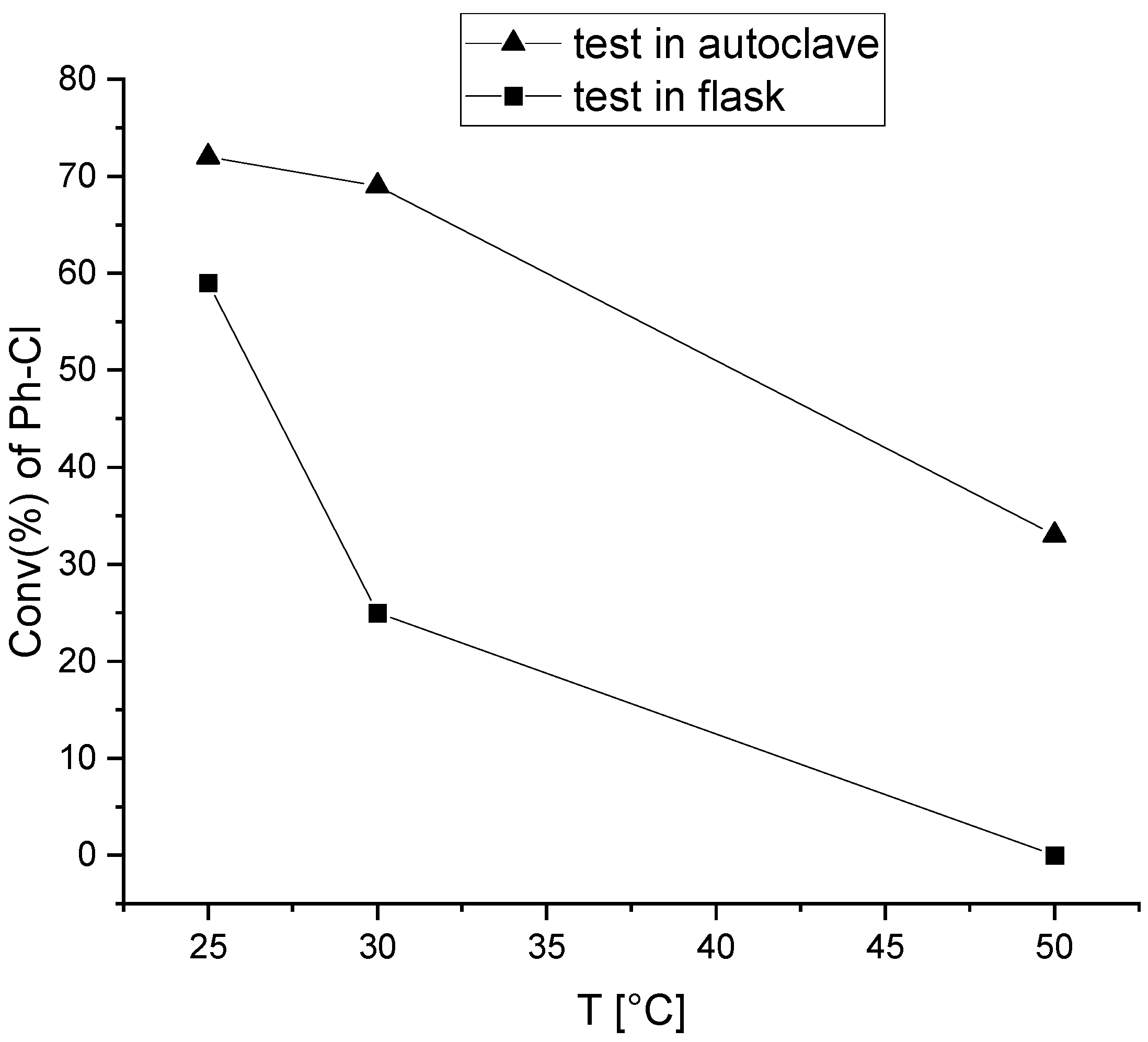
The effect of temperature on dehalogenation efficiency was investigated.
Initial tests were carried out at room temperature (25 °C). However, the room temperature was not controlled, and therefore, the reactions’ performance varied significantly depending on external conditions. Due to this issue, controlled temperature tests were conducted, specifically at 30 °C and 50 °C, to assess the effect of higher temperatures on dehalogenation efficiency.
Although the autoclave had previously demonstrated better performance than the round-bottom flask, the effect of temperature was investigated in both setups to provide a comprehensive comparison (Figure 6).
The following results were obtained in a round-bottom flask: Test 5 (Table 1) at 25 °C yielded 59% conversion, Test 8 (Table 1) at 30 °C dropped sharply to 25%, and Test 9 (Table 1) at 50 °C gave no quantifiable conversion (0%). This last outcome can be attributed to a variation in catalytic activity as the temperature increases, because at high temperatures, the gas solubility is lower.
Figure 6. Influence of temperature on chlorobenzene dehalogenation efficiency.
Sustainability 18 02485 g006
In the autoclave, the results were more favorable but still showed a declining trend with increasing temperature: Test 2 (Table 1) at 25 °C reached 72% conversion, Test 10 (Table 1) at 30 °C achieved 69%, and Test 11 (Table 1) at 50 °C dropped to 33%.
This behavior is consistent with the reaction mechanism and can be explained by the temperature dependence of gas solubility, which may be one of the main factors. The dissolution of gases in liquids is generally an exothermic process; therefore, as temperature increases, the equilibrium solubility of gaseous H2 decreases. As a result, the concentration of dissolved hydrogen available for catalytic reduction decreases at higher temperatures, leading to lower overall conversion efficiency.
Taken together, these findings indicate that in both configurations the efficiency of the catalytic system decreases with rising temperature. While the best conversions were observed at room temperature, these results were not considered fully reliable due to fluctuations in the laboratory temperature caused by external environmental conditions.

3.1.4. Influence of (NH4)2Ni(SO4)2·6H2O in the Catalytic System

Once the optimal operating conditions had been defined, additional experiments were conducted to evaluate the contributions of individual catalytic species. In particular, the role of (NH4)2Ni(SO4)2·6H2O was assessed by selectively excluding the salt from the reaction mixture.
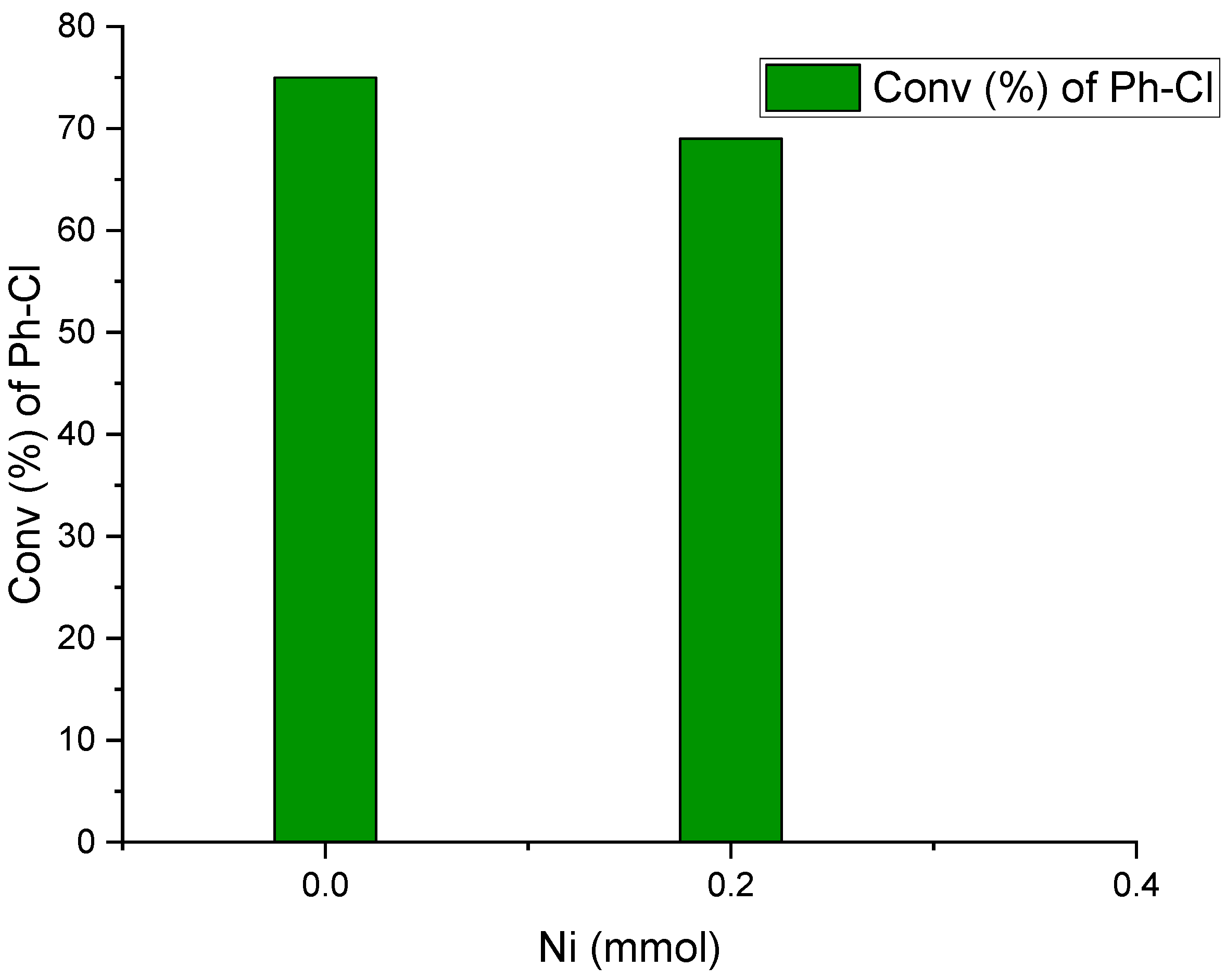
In Test 12 (Table 1), where nickel salt was omitted, conversion increased to 75%, higher than 69% registered in Test 10 (Table 1), which included (NH4)2Ni(SO4)2·6H2O under otherwise identical conditions (Figure 7). This suggests a potential inhibitory effect of nickel salts, possibly due to competition between Ni2+ and H+ ions (introduced with the nickel salt) and Fe2+ during the reduction process mediated by NaBH4. Interestingly, this outcome contrasts with several reports in the literature [31,32,33], where Ni-based catalysts are generally beneficial for enhancing the catalytic activity of zero-valent iron. However, an excessive nickel loading may instead hinder the catalytic dehalogenation performance due to competing hydrogen evolution reactions and limited electron transfer efficiency [39,40]. Moreover, excessive Ni coverage on the nZVI surface can restrict electron transfer from iron to the substrate and promote partial surface oxidation, ultimately leading to lower dechlorination efficiency [39,41].
Based on extensive literature evidence indicating that the chemical reduction of ferrous salts with sodium borohydride typically leads to the formation of nanoscale zero-valent iron (nZVI) [42,43,44,45,46,47], it is reasonable to identify the in situ formed product in this study as nZVI.
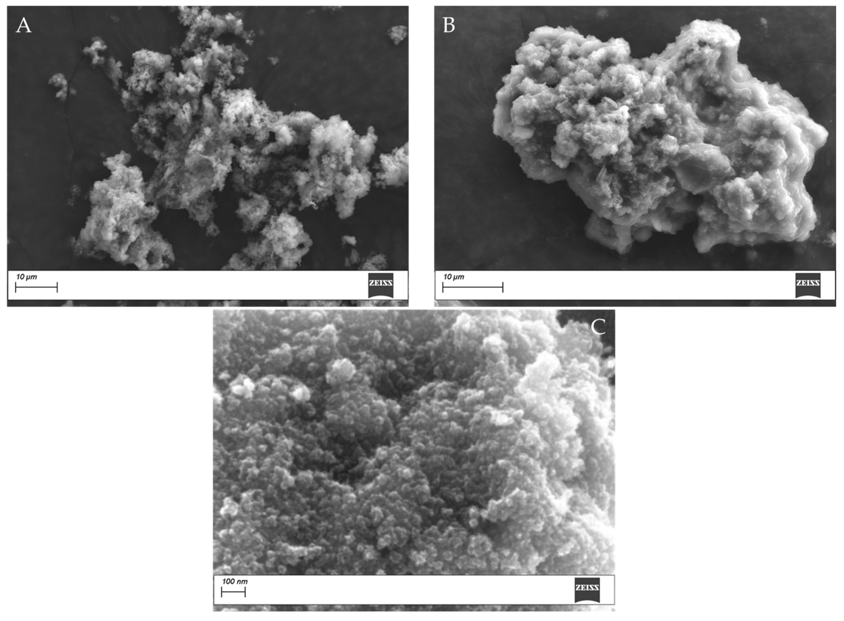
SEM analyses were performed to verify the morphology of the solid products obtained in this study and to assess the possible influence of nickel addition.
The SEM images reveal a comparable morphology for the two samples obtained in the presence (Figure 8A) and absence (Figure 8B) of nickel, indicating that the addition of nickel does not significantly affect the resulting morphology. In both cases, the formation of agglomerates composed of nanoparticles is observed, with a characteristic size on the order of several tens of thousands of nanometers.
In addition to gaining insight into the catalytic active species of the system constituted of FeSO4·7H2O in the absence of (NH4)2Ni(SO4)2·6H2O, a SEM image of the resulting black catalyst powder with a high magnification (Figure 8C) was analyzed, revealing the formation of spherical type nanoparticles of mean diameter of 36 ± 13 nm, in accordance with literature results [30].

3.2. Applicability to Brominated Compounds

Finally, the optimized protocol was extended to brominated compound substrates and binary mixtures of Ph-Cl and Ph-Br to test its broader applicability.
Although bromine is typically a better leaving group than chlorine, experimental validation was necessary to confirm the system’s performance. In Test 13 (Table 1), complete debromination of Ph-Br was achieved (100% conversion). In Test 14 (Table 1), a 1:1 mixture of Ph-Cl and Ph-Br was used to explore potential competitive effects. The results showed complete conversion of Ph-Br and a 95% conversion of Ph-Cl. These findings confirm the system’s high efficiency and demonstrate its suitability in treating mixed halogenated substrates.
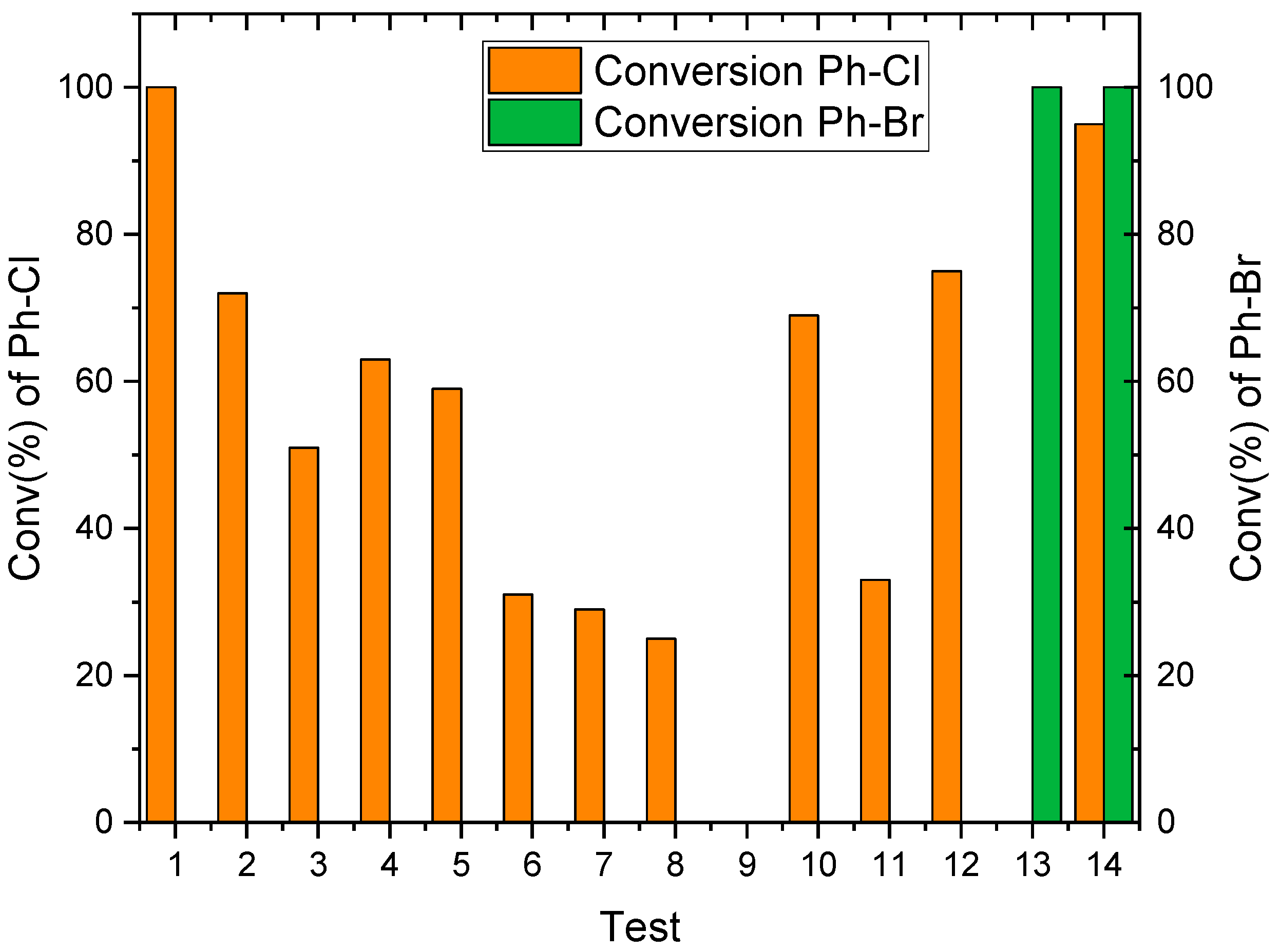
The overall overview of the experimental tests summarized in Table 1 is reported in Figure 9, which visually highlights the best catalytic performance.

3.3. Mechanism of the Reaction

The proposed reaction mechanism is depicted in Figure 10.
Describing the reaction mechanism in more detail, FeSO4·7H2O reacts in the presence of NaBH4 with the simultaneous formation of nZVI nanoparticles and the release of hydrogen gas.
Once nZVI has formed, in the presence of halogenated organic compounds (Ar-X), oxidative addition occurs, leading to the formation of Ar+ and X ions, which bind to the iron nanoparticles. At this stage, thanks to the presence of molecular hydrogen (H2), metal hydride compounds develop on the nZVI before giving transmigration from an iron atom to the other. Finally, nZVI becomes available again following a reductive elimination reaction in which Ar-H and H-X compounds form, enabling the elimination of halides.
Figure 10. Scheme illustrating the possible catalytic cycle involved in the hydrodehalogenation process.
Sustainability 18 02485 g010

4. Conclusions and Future Developments

This study investigated the effectiveness of catalytic hydrodehalogenation of Chlorobenzene and Bromobenzene for WEEE cycle closure. The main novelty of this study lies in the generation of nano zero-valent iron (nZVI) within the CHD reactor (in situ) without the addition of strong acids; this allows for a reduction in catalyst dosage without any loss of performance.
The results further indicate that increasing the NaBH4 dosage does not necessarily enhance dehalogenation efficiency. In both autoclave and round-bottom flask configurations, the highest conversions were achieved at the lowest dosage (5 mmol), demonstrating that minimal amounts of NaBH4 are sufficient and supporting the protocol’s resource efficiency.
The better performance observed in the autoclave highlights the importance of controlled reaction conditions and hydrogen availability, supporting the hypothesis that iron reduction and molecular hydrogen occur simultaneously. Operating at a 1:1 molar ratio of FeSO4·7H2O to Ph-Cl still ensured satisfactory conversion (72%), improving both the sustainability and cost-effectiveness of the process.
Temperature was identified as a critical parameter: temperatures below 30 °C proved to be optimal, whereas higher temperatures may hinder the process. This behaviour is consistent with the decreased solubility of hydrogen gas in the solvent at elevated temperatures, which limits its availability for the reduction process.
In addition, the omission of (NH4)2Ni(SO4)2·6H2O enhances conversion efficiency, suggesting a possible inhibitory role, potentially linked to competition with Fe2+ species during the reduction mechanism.
The catalytic system also demonstrated high effectiveness toward brominated substrates, achieving complete debromination of Ph-Br. In mixed halogenated systems, full debromination and up to 95% dechlorination were obtained, confirming the robustness of the system and demonstrating its applicability to mixed halogenated substrates without mutual interference.
The proposed approach has the potential to be used not only for upgrading pyrolysis oil, but also for the remediation of hazardous halogenated organic pollutants, such as polychlorinated biphenyls (PCBs), polychlorinated dibenzo-p-dioxins (PCDDs), and dibenzofurans (PCDFs). Further research is therefore required to assess its applicability in more complex matrices.

Supplementary Materials

The following supporting information can be downloaded at: https://www.mdpi.com/article/10.3390/su18052485/s1, Figure S1: Spectra related to the calibration line: A (1 mmol), B (0.8 mmol), C (0.4 mmol), D (0.2 mmol).; Figure S2: Chlorobenzene calibration curve.; Figure S3: Bromobenzene calibration curve.Table S1: The composition of the four solutions of known concentration required to execute the chlorobenzene calibration curve; Table S2: Composition of the four solutions of known concentration for the execution of the chlorobenzene calibration curve.

Author Contributions

Conceptualization, B.M.F., M.E.D.C. and M.M.D.; methodology, M.E.D.C. and M.M.D.; validation, M.E.D.C. and F.T.; formal analysis, M.E.D.C.; investigation, B.M.F. and M.E.D.C.; data curation, M.E.D.C.; writing—original draft preparation, B.M.F. and M.E.D.C.; writing—review and editing, F.T., M.M.D., P.F.G. and M.N.; visualization, B.M.F. and M.E.D.C.; supervision, M.M.D., P.F.G. and M.N. All authors have read and agreed to the published version of the manuscript.

Funding

This research received no external funding.

Institutional Review Board Statement

Not applicable.

Informed Consent Statement

Not applicable.

Data Availability Statement

The original contributions presented in this study are included in the article. Further inquiries can be directed to the corresponding author.

Acknowledgments

The authors gratefully acknowledge Department of Environmental, Landscape and Urban Quality of Apulia Region (Collaboration agreement on studies, analysis, and research on the sustainable management of urban waste aimed at updating the Waste Management Regional Plan and ensuring the achievement of the strategic objectives set out).

Conflicts of Interest

The authors declare no conflicts of interest.

Abbreviations

The following abbreviations are used in this manuscript:
WEEEWaste from Electrical and Electronic Equipment
EEEElectrical and Electronic Equipment
CHDCatalytic Hydrodehalogenation
nZVINano Zero-Valent Iron

References

  1. Maqsood, T.; Dai, J.; Zhang, Y.; Guang, M.; Li, B. Pyrolysis of plastic species: A review of resources and products. J. Anal. Appl. Pyrolysis 2021, 159, 105295. [Google Scholar] [CrossRef] [Scilit]
  2. Kartik, S.; Balsora, H.K.; Sharma, M.; Saptoro, A.; Jain, R.K.; Joshi, J.B.; Sharma, A. Valorization of plastic wastes for production of fuels and value-added chemicals through pyrolysis—A review. Therm. Sci. Eng. Prog. 2022, 32, 101316. [Google Scholar] [CrossRef] [Scilit]
  3. Pyshye, S.; Lypko, Y.; Demchuk, Y.; Kukhar, O.; Korchak, B.; Pochapska, I.; Zhytnetskyi, I. Characteristics and applications of waste tire pyrolysis products: A review. Chem. Chem. Technol. 2024, 18, 244–257. [Google Scholar] [CrossRef] [Scilit]
  4. Kumar, A.; Kumari, L.; Laghari, A.A.; Rong, H.; Jamro, I.A.; Sajnani, S.; Aborisade, M.A.; Rajput, G.; Oba, B.T.; Nkinahamira, F.; et al. Exploring the integrated potential of pyrolysis and low-temperature wet torrefaction for typical medical waste valorization: A multifaceted approach leveraging online TG-FTIR-MS, 2D-COS, iso-conversional kinetics, and reaction mechanisms. Chem. Eng. J. 2024, 499, 156464. [Google Scholar] [CrossRef] [Scilit]
  5. Yang, X.; Sun, L.; Xiang, J.; Hu, S.; Su, S. Pyrolysis and dehalogenation of plastics from waste electrical and electronic equipment (WEEE): A review. Waste Manag. 2013, 33, 462–473. [Google Scholar] [CrossRef] [Scilit] [PubMed]
  6. Cuevas, A.B.; Leiva-Candia, D.E.; Dorado, M.P. An Overview of Pyrolysis as Waste Treatment to Produce Eco-Energy. Energies 2024, 17, 2852. [Google Scholar] [CrossRef] [Scilit]
  7. Falco, B.M.; Di Clemente, M.E.; Fersini, E.; Dell’Anna, M.M.; Todaro, F.; Notarnicola, M. Catalytic Hydro-Dehalogenation Optimization of Pyrolysis Oil from Weee Plastics. In Proceedings of the 13th International Conference on Environmental Engineering and Management; Marilena-Adela, B., Daniela, G., Gabriela-Antoaneta, A., Alexandra-Cristina, B., George, B., Daniela, F., Petronela, C., Adrian-Catalin, P., Eds.; ECOZONE Publishing House: Iasi, Romania, 2025; pp. 75–76. [Google Scholar]
  8. Fersini, E.; Giuliano, A.; Todaro, F.; Wieth, C.; Notarnicola, M. Evaluation of sewage sludge treatment by pilot pyrolysis plant and laboratory analysis. In Proceedings VENICE 2024; CISA Publisher: Padova, Italy, 2024. [Google Scholar]
  9. Farooq, M.Z.; Yu, H.; Lin, F.; Rajput, M.I.; Kumar, A.; Chen, G. Kinetic insights and pollution mitigation in waste tire pyrolysis: Targeting sulfur, nitrogen, and PAHs emissions. J. Anal. Appl. Pyrolysis 2024, 181, 2024. [Google Scholar] [CrossRef] [Scilit]
  10. Perez-Martinez, B.B.; Lopez-Urionabarrenechea, A.; Serras-Malillos, A.; Acha, E.; Martínez-Santos, M.; Caballero, B.M.; Iturrondobeitia, M.; Afonso, H. Recycling of plastic-rich streams from waste electrical and electronic equipment (WEEE) sorting plants: An in-depth study of pyrolysis potential through product characterization and life cycle assessment (LCA). Energy Convers. Manag. 2025, 329, 119633. [Google Scholar] [CrossRef] [Scilit]
  11. Parajuly, K.; Habib, K.; Liu, G. Waste electrical and electronic equipment (WEEE) in Denmark: Flows, quantities and management. Resour. Conserv. Recycl. 2017, 123, 85–92. [Google Scholar] [CrossRef] [Scilit]
  12. Baldé, C.P.; Kuehr, R.; Yamamoto, T.; McDonald, R.; D’Angelo, E.; Althaf, S.; Bel, G.; Deubzer, O.; Fernandez-Cubillo, E.; Forti, V.; et al. Michelle Wagner Global E-Waste Monitor 2024; International Telecommunication Union (ITU) and United Nations Institute for Training and Research (UNITAR): Geneva, Switzerland; Bonn, Germany, 2024. [Google Scholar]
  13. Fiorente, A.; D’Agostino, G.; Petrella, A.; Todaro, F.; Notarnicola, M. Recovery of Plastics from WEEE through Green Sink–Float Treatment. Materials 2024, 17, 3041. [Google Scholar] [CrossRef] [Scilit]
  14. Stefano, L.S.; Cafiero, L.; De Angelis, D.; Pavoni, S.; Tuffi, R.; Scarsella, M. Thermal pyrolysis of a real plastic sample from small WEEE and characterization of the produced oil in view of fuel or feedstock uses. Therm. Sci. Eng. Prog. 2024, 48, 102403. [Google Scholar] [CrossRef] [Scilit]
  15. Ibanescu, D.; Cailean, D.; Teodosiu, C.; Fiore, S. Assessment of the waste electrical and electronic equipment management systems profile and sustainability in developed and developing European Union countries. Waste Manag. 2018, 73, 39–53. [Google Scholar] [CrossRef] [Scilit] [PubMed]
  16. Watson, A.; Brigden, K.; Shinn, M.; Cobbing, M. Toxic Transformers; A Review of the Hazards of Brominated & Chlorinated Substances in Electrical and Electronic Equipment; Greenpeace Research Laboratories Technical Note; Greenpeace: Amsterdam, The Netherlands, 2010. [Google Scholar]
  17. Das, P.; Gabriel, J.C.P.; Tay, C.Y.; Lee, J.M. Value-added products from thermochemical treatments of contaminated e-waste plastics. Chemosphere 2021, 269, 129409. [Google Scholar] [CrossRef] [Scilit] [PubMed]
  18. Joo, J.; Kwon, E.E.; Lee, J. Achievements in pyrolysis process in E-waste management sector. Environ. Pollut. 2021, 287, 117621. [Google Scholar] [CrossRef] [Scilit] [PubMed]
  19. Martinho, G.; Pires, A.; Saraiva, L.; Ribeiro, R. Composition of plastics from waste electrical and electronic equipment (WEEE) by direct sampling. Waste Manag. 2012, 32, 1213–1217. [Google Scholar] [CrossRef] [Scilit]
  20. Ranskiy, A.; Gordienko, O.; Korinenko, B.; Ishchenko, V.; Sakalova, H.; Vasylinych, T.; Malovanyy, M.; Kryklyvyi, R. Pyrolysis processing of polymer waste components of electronic products. Chem. Chem. Technol. 2024, 18, 103–108. [Google Scholar] [CrossRef] [Scilit]
  21. López, J.; Amodio, L.; Alonso-Doncel, M.d.M.; Cueto, J.; Hernando, H.; Mazur, M.; Čejka, J.; Pizarro, P.; Serrano, D.P. Enhanced oil dehalogenation during catalytic pyrolysis of WEEE-derived plastics over Fe- and Ca-modified zeolites. J. Environ. Chem. Eng. 2024, 12, 111790. [Google Scholar] [CrossRef] [Scilit]
  22. Sakata, Y.; Bhaskar, T.; Uddin, M.A.; Muto, A.; Matsui, T. Development of a catalytic dehalogenation (Cl, Br) process for municipal waste plastic-derived oil. J. Mater. Cycles Waste Manag. 2003, 5, 113–124. [Google Scholar] [CrossRef] [Scilit]
  23. Evangelopoulos, P.; Kantarelis, E.; Yang, W. Waste electric and electronic equipment: Current legislations, waste management, and recycling of energy, materials, and feedstocks. In Sustainable Resource Recovery and Zero Waste Approaches; Elsevier: Amsterdam, The Netherlands, 2019; pp. 239–266. [Google Scholar] [CrossRef] [Scilit]
  24. Luda, M.P.; Balabanovich, A.I. Thermal hydrodehalogenation of 2,4-dibromophenol by polymeric materials. J. Anal. Appl. Pyrolysis 2011, 90, 63–71. [Google Scholar] [CrossRef] [Scilit]
  25. Hubáček, J.; Lederer, J.; Kuráň, P.; Koutník, P.; Gholami, Z.; Zbuzek, M.; Bačiak, M. Dechlorination during pyrolysis of plastics: The potential of stepwise pyrolysis in combination with metal sorbents. Fuel Process. Technol. 2022, 231, 107226. [Google Scholar] [CrossRef] [Scilit]
  26. Shen, M.; Syn, W.H. Hydrodebromination of bromoarenes using Grignard reagents catalyzed by metal ions. Appl. Organomet. Chem. 2009, 23, 51–54. [Google Scholar] [CrossRef] [Scilit]
  27. Amodio, L.; López, J.; Souza, A.; Cueto, J.; Hernando, H.; Pizarro, P.; Serrano, D. Simultaneous removal of brominated and chlorinated species during the production of oils by e-waste plastics catalytic hydropyrolysis. J. Hazard. Mater. 2024, 465, 2024. [Google Scholar] [CrossRef] [Scilit] [PubMed]
  28. Wu, W.; Xu, J.; Ohnishi, R. Complete hydrodechlorination of chlorobenzene and its derivatives over supported nickel catalysts under liquid phase conditions. Appl. Catal. B 2005, 60, 129–137. [Google Scholar] [CrossRef] [Scilit]
  29. Vasile, C.; Brebu, M.A.; Karayildirim, T.; Yanik, J.; Darie, H. Feedstock recycling from plastics and thermosets fractions of used computers. II. Pyrolysis oil upgrading. Fuel 2007, 86, 477–485. [Google Scholar] [CrossRef] [Scilit]
  30. Balda, M.; Kopinke, F.D. The role of nickel traces in fine chemicals for hydrodechlorination reactions with zero-valent iron. Chem. Eng. J. 2020, 388, 124185. [Google Scholar] [CrossRef] [Scilit]
  31. Chekli, L.; Bayatsarmadi, B.; Sekine, R.; Sarkar, B.; Shen, A.M.; Scheckel, K.; Skinner, W.; Naidu, R.; Shon, H.; Lombi, E.; et al. Analytical characterisation of nanoscale zero-valent iron: A methodological review. Anal. Chim. Acta 2016, 903, 13–35. [Google Scholar] [CrossRef] [Scilit]
  32. Balaraman, E.; Nandakumar, A.; Jaiswal, G.; Sahoo, M.K. Iron-catalyzed dehydrogenation reactions and their applications in sustainable energy and catalysis. Catal. Sci. Technol. 2017, 7, 3177–3195. [Google Scholar] [CrossRef] [Scilit]
  33. Liu, M.; Chen, G.; Xu, L.; He, Z.; Ye, Y. Environmental remediation approaches by nanoscale zero valent iron (nZVI) based on its reductivity: A review. RSC Adv. 2024, 14, 21118–21138. [Google Scholar] [CrossRef] [Scilit]
  34. Charitopoulou, M.A.; Kalogiannis, K.G.; Lappas, A.A.; Achilias, D.S. Novel trends in the thermo-chemical recycling of plastics from WEEE containing brominated flame retardants. Environ. Sci. Pollut. Res. 2020, 28, 59190–59213. [Google Scholar] [CrossRef] [Scilit]
  35. Namakka, M.; Rahman, M.R.; Said, K.A.B.M.; Muhammad, A. Insights into micro-and nano-zero valent iron materials: Synthesis methods and multifaceted applications. RSC Adv. 2024, 14, 30411–30439. [Google Scholar] [CrossRef] [Scilit]
  36. Leal-Duaso, A.; Fraile, J.M. Chloroaromatics remediation: Insights into the chemical reduction and hydrodechlorination of chlorobenzenes. Crit. Rev. Environ. Sci. Technol. 2025, 55, 1–29. [Google Scholar] [CrossRef] [Scilit]
  37. Leal-Duaso, A.; Salvatella, L.; Fraile, J.M. Physical-chemical transformations for the remediation and valorization of hexachlorocyclohexanes (HCHs) including lindane: A review. J. Environ. Manag. 2025, 375, 124262. [Google Scholar] [CrossRef] [Scilit] [PubMed]
  38. Amendola, S.C.; Sharp-Goldman, S.L.; Janjua, M.S.; Spencer, N.C.; Kelly, M.T.; Petillo, P.J.; Binder, M. A safe, portable, hydrogen gas generator using aqueous borohydride solution and Ru catalyst. Int. J. Hydrogen Energy 2000, 25, 969–975. [Google Scholar] [CrossRef] [Scilit]
  39. Huang, B.; Qian, W.; Yu, C.; Wang, T.; Zeng, G.; Lei, C. Effective catalytic hydrodechlorination of o-, p- and m-chloronitrobenzene over Ni/Fe nanoparticles: Effects of experimental parameter and molecule structure on the reduction kinetics and mechanisms. Chem. Eng. J. 2016, 306, 607–618. [Google Scholar] [CrossRef] [Scilit]
  40. Kim, J.H.; Tratnyek, P.G.; Chang, Y.S. Rapid dechlorination of polychlorinated dibenzo-p-dioxins by bimetallic and nanosized zerovalent iron. Environ. Sci. Technol. 2008, 42, 4106–4112. [Google Scholar] [CrossRef] [Scilit]
  41. Nie, X.; Liu, J.; Zeng, X.; Yue, D. Rapid degradation of hexachlorobenzene by micron Ag/Fe bimetal particles. J. Environ. Sci. 2013, 25, 473–478. [Google Scholar] [CrossRef] [Scilit]
  42. Zhu, B.W.; Lim, T.T. Catalytic reduction of chlorobenzenes with Pd/Fe nanoparticles: Reactive sites, catalyst stability, particle aging, and regeneration. Environ. Sci. Technol. 2007, 41, 7523–7529. [Google Scholar] [CrossRef] [Scilit]
  43. Li, Y.; Li, X.; Han, D.; Huang, W.; Yang, C. New insights into the role of Ni loading on the surface structure and the reactivity of nZVI toward tetrabromo- and tetrachlorobisphenol A. Chem. Eng. J. 2017, 311, 173–182. [Google Scholar] [CrossRef] [Scilit]
  44. Li, Y.; Li, X.; Xiao, Y.; Wei, C.; Han, D.; Huang, W. Catalytic debromination of tetrabromobisphenol A by Ni/nZVI bimetallic particles. Chem. Eng. J. 2016, 284, 1242–1250. [Google Scholar] [CrossRef] [Scilit]
  45. Eljamal, O.; Mokete, R.; Matsunaga, N.; Sugihara, Y. Chemical pathways of Nanoscale Zero-Valent Iron (NZVI) during its transformation in aqueous solutions. J. Environ. Chem. Eng. 2018, 6, 6207–6220. [Google Scholar] [CrossRef] [Scilit]
  46. Reddy, A.V.B.; Yusop, Z.; Jaafar, J.; Reddy, Y.V.M.; Bin Aris, A.; Majid, Z.A.; Talib, J.; Madhavi, G. Recent progress on Fe-based nanoparticles: Synthesis, properties, characterization and environmental applications. J. Environ. Chem. Eng. 2016, 4, 3537–3553. [Google Scholar] [CrossRef] [Scilit]
  47. Pang, Z.; Jia, X.; Liu, K.; Wang, Z.; Luo, Q.; Luo, J. Preparation, characterization and their performance of the supported nanoscale zero-valent iron materials with different iron contents. Adv. Mater. Res. 2012, 573–574, 155–162. [Google Scholar] [CrossRef] [Scilit]
Figure 2. Visual evidence of catalytic system activation. Left: initial mixture containing NaBH4, FeSO4·7H2O and (NH4)2Ni(SO4)2·6H2O. Right: formation of black Fe0 (nZVI) following the reaction. The accompanying equations illustrate molecular hydrogen generation and the subsequent reduction of Fe2+ to nano zero-valent iron (nZVI).
Sustainability 18 02485 g002
Figure 7. Effect of Ni(NH4)2(SO4)2·6H2O on chlorobenzene conversion efficiency.
Sustainability 18 02485 g007
Figure 8. SEM images of sample 11 containing Ni (A), sample 12 without Ni (B), and sample 14 without Ni with higher magnification (C).
Sustainability 18 02485 g008
Figure 9. Comprehensive overview of conversion performance across all catalytic hydrodehalogenation experiments.
Sustainability 18 02485 g009
Table 1. Overview of reaction conditions employed in the catalytic hydrodehalogenation tests.
TestSystemPh-ClPh-BrFeSO4·7H2O(NH4)2Ni(SO4)2·6·H2ONaBH4TConv%
[mmol][mmol][mmol][mmol][mmol][°C][%]
1Autoclave1-511525100
21-10.252572
31-10.2102551
41-10.2152563
5Round-bottom Flask1-10.252559
61-10.2102531
71-10.2152529
81-10.253025
91-10.25500
10Autoclave1-10.253069
111-10.255033
121-1-53075
13-11-530100
140.50.51-530100 (Ph-Br)
95 (Ph-Cl)
Table 2. Initial and final halogen for each CHD tests.
TestPh-Cl,iPh-Cl,fPh-Br,iPh-Br,fConv%
[g][g][g][g][%]
10.1120.00--100
20.1120.031--72
30.1120.055--51
40.1120.041--63
50.1120.046--59
60.1120.077--31
70.1120.080--29
80.1120.084--25
90.1120.112--0
100.1120.035--69
110.1120.075--33
120.1120.028--75
13- 0.1570.00100
14 0.0780.00100 (Ph-Br)
0.0560.003 95 (Ph-Cl)
Disclaimer/Publisher’s Note: The statements, opinions and data contained in all publications are solely those of the individual author(s) and contributor(s) and not of MDPI and/or the editor(s). MDPI and/or the editor(s) disclaim responsibility for any injury to people or property resulting from any ideas, methods, instructions or products referred to in the content.