3.1. Single-Stage PV–ESS Grid-Connected Operation Mode
The stability of Bus1 and the MPPT of the PV module are achieved through three-phase converter control. The ESS performs charge and discharge control according to the system’s overall energy efficiency optimization requirements. The stability of Bus2 and the ESS charge/discharge operations are realized via DHB control. HVRT is accomplished by controlling the voltage at Port3 uPort3.
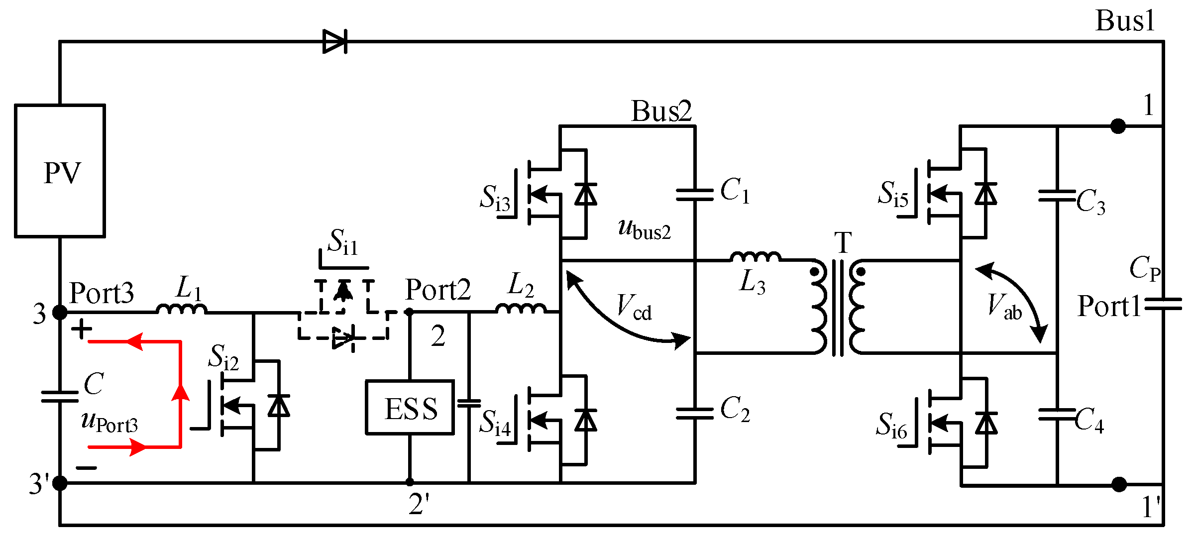
Under normal operating conditions, Port3 remains inactive, meaning switch
Si2 stays closed. In this state, all PV power is delivered to the DC bus side. If the PV power is insufficient, the storage system supplies energy to the DC bus via the DHB. If the PV power exceeds demand, the surplus energy is transferred from the DC bus to the storage device through the DHB. The operational modes are illustrated in
Figure 7.
The control scheme for the Bus1 voltage
uBus1 is shown in
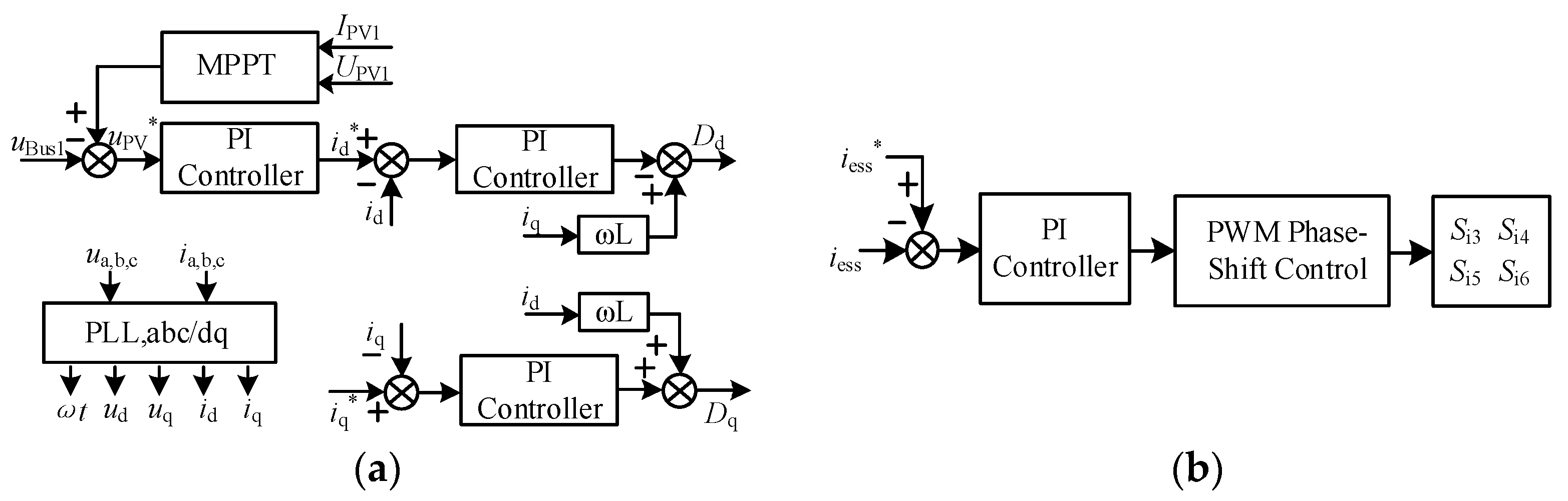
Figure 8a. Under grid-connected operation, a dual-loop control of voltage and current is employed to maintain real-time matching between voltage and power, ensuring stable DC bus voltage. By adjusting the bus voltage, MPPT for the PV module is achieved. Under different operating conditions, the converter can operate in either inverter or rectifier mode to meet system requirements.
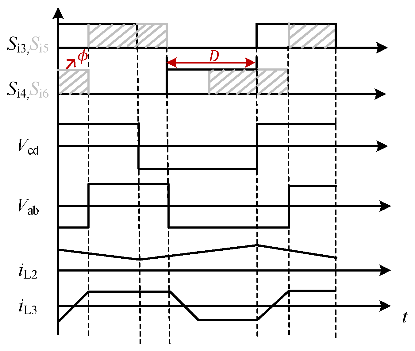
The flow of ESS energy is controlled by DHB, as shown in
Figure 8b, using a classical phase-shift control method. The energy storage current
iess is compared with its reference value
iess*, and the resulting signal is processed through phase-shifted PWM to generate duty cycle signals that control the complementary conduction of switches
Si3 and
Si4, as well as
Si5 and
Si6. A phase difference exists between the drive signals of adjacent bridge arms, enabling control over the direction of energy flow.
3.2. PV–ESS Grid-Connected High-Voltage Ride-Through Mode
When symmetrical voltage swell fault occurs at the point of common coupling, the AC-side voltage of the grid-tied inverter rises sharply. For conventional single-stage photovoltaic grid-connected topologies, the DC-link voltage will be pulled up accordingly. Once the DC bus voltage exceeds the withstand threshold of power devices, overvoltage protection will be triggered, and the inverter will be forced to disconnect from the utility grid. Large-scale tripping of distributed PV units further causes power imbalance, aggravates voltage fluctuation and endangers the security and stability of the whole power grid, which makes high-voltage ride-through an indispensable capability for grid-tied renewable energy systems according to modern grid codes.
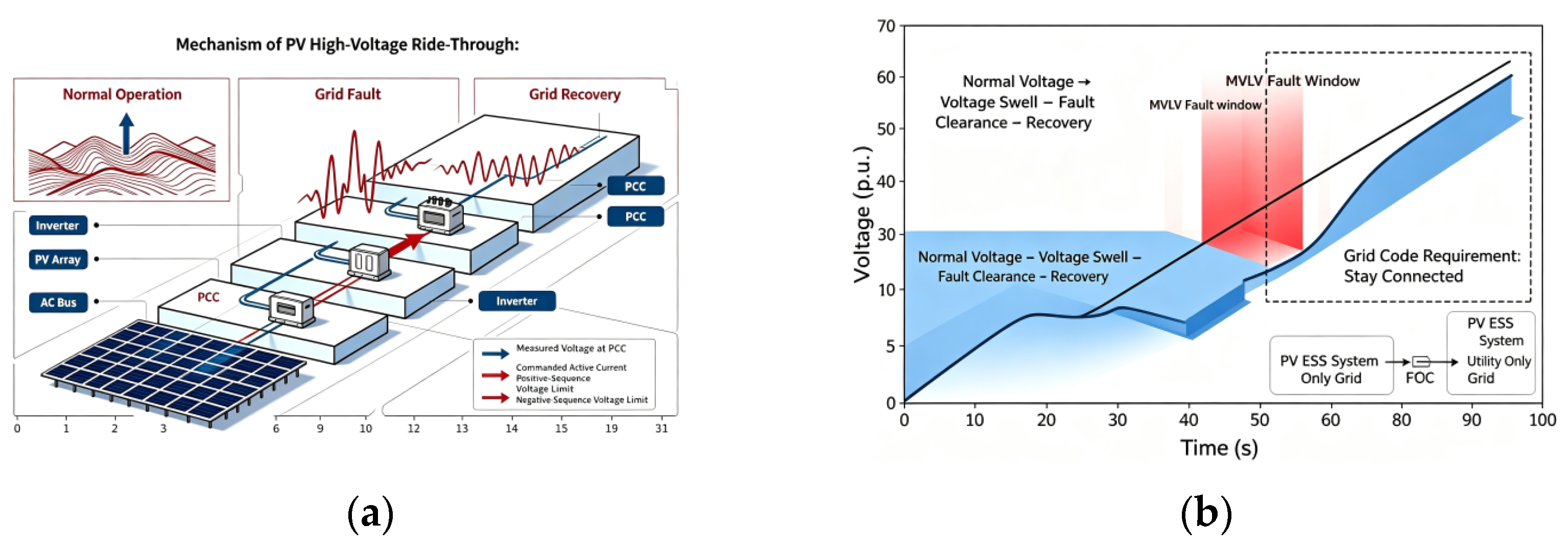
The conceptual diagrams shown in
Figure 9 illustrate the macroscopic operating behavior and grid-code requirement of HVRT. Under normal operation conditions, the PV–ESS system transfers power to the utility grid following given power dispatching commands. When grid voltage swell takes place during the fault window, the system is required to remain connected rather than trip off immediately. It should maintain continuous operation throughout the fault duration and keep tracking the maximum power point of photovoltaic arrays. After fault clearance and grid voltage returns to the allowable range, the system smoothly resumes its pre-fault normal grid-tied operation state.
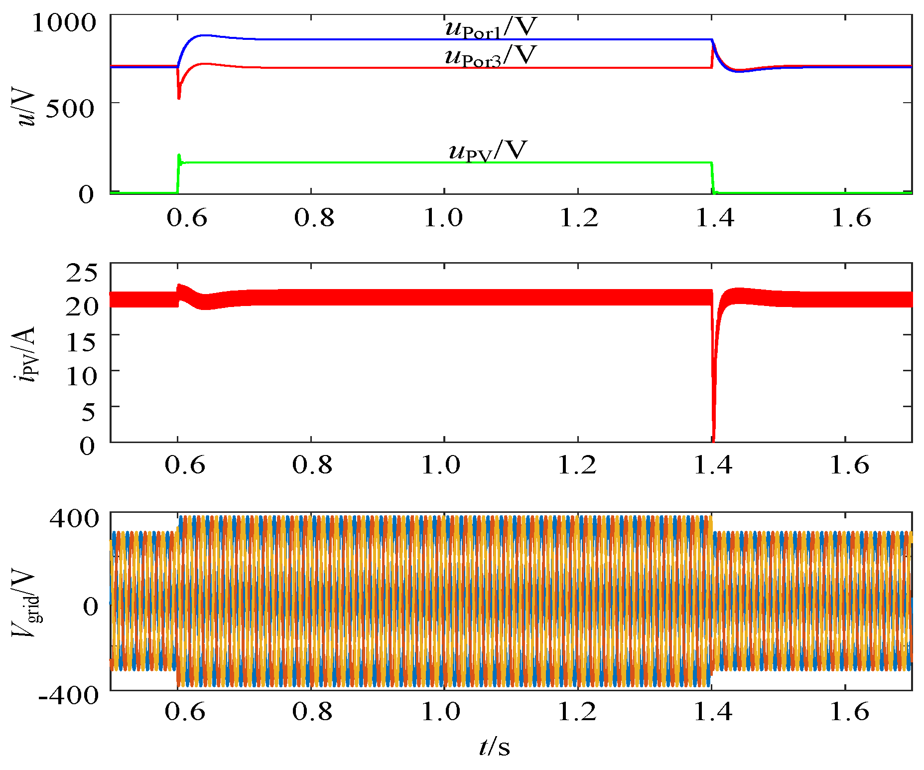
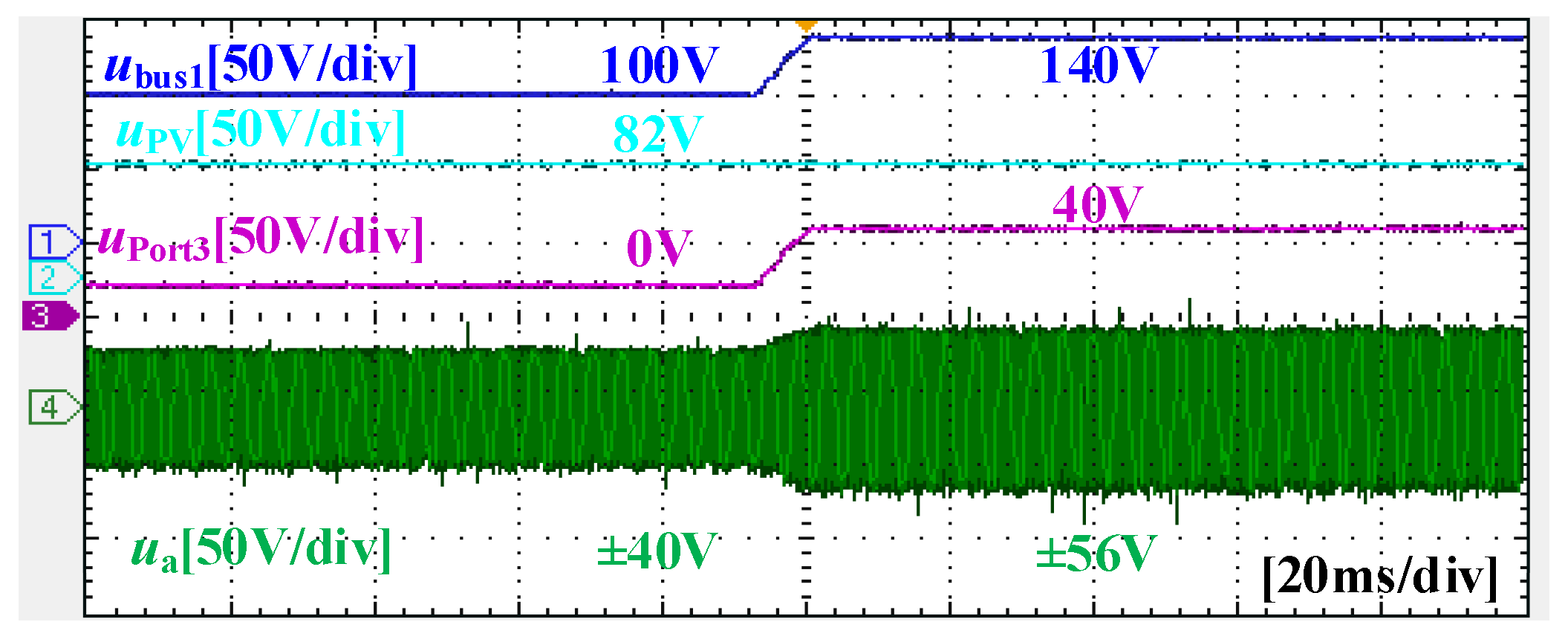
To ensure that the PV array can continuously perform MPPT control during energy variations, the voltage at Port3 uPort3 must be adjusted in real-time to maintain the PV array’s output voltage at the required level for maximum power tracking.
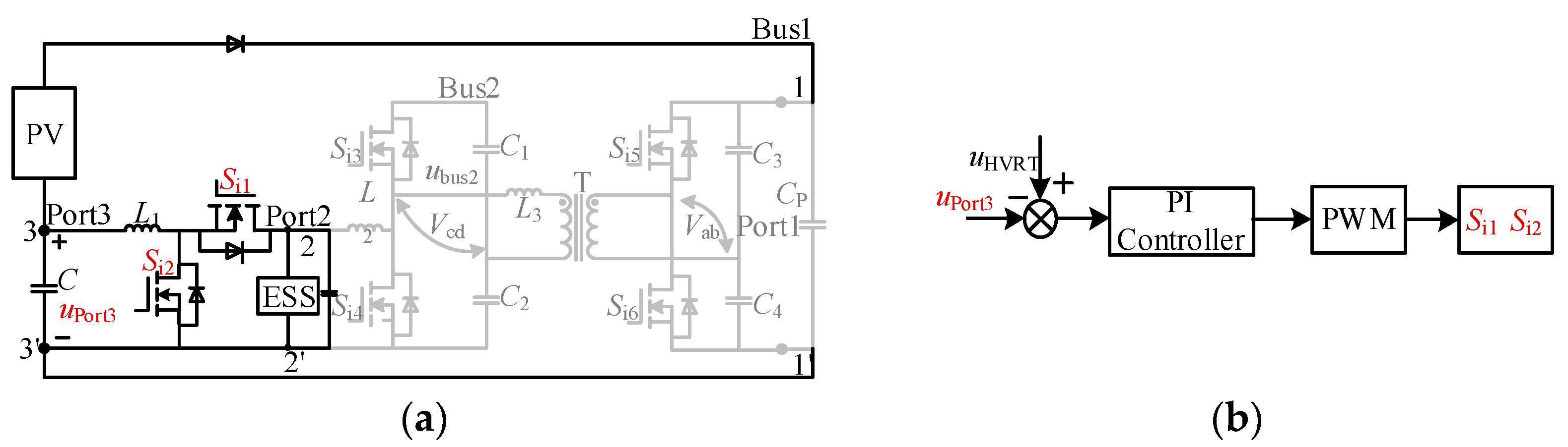
The HVRT operation mode is shown in
Figure 10b. During the HVRT process, Port3 becomes active, and the voltage at Port1
uPort1 equals the sum of the
uPort3 and the PV output voltage
uPV, where
uPV is determined by the MPPT.
To raise the DC bus voltage
uPort1, the
uPort3 is also increased, with the required increment being
uPort3 =
uPort1 −
uPV. HVRT is achieved by controlling the voltage at Port3. The control scheme for Port3 voltage
uPort3 is shown in
Figure 10a.
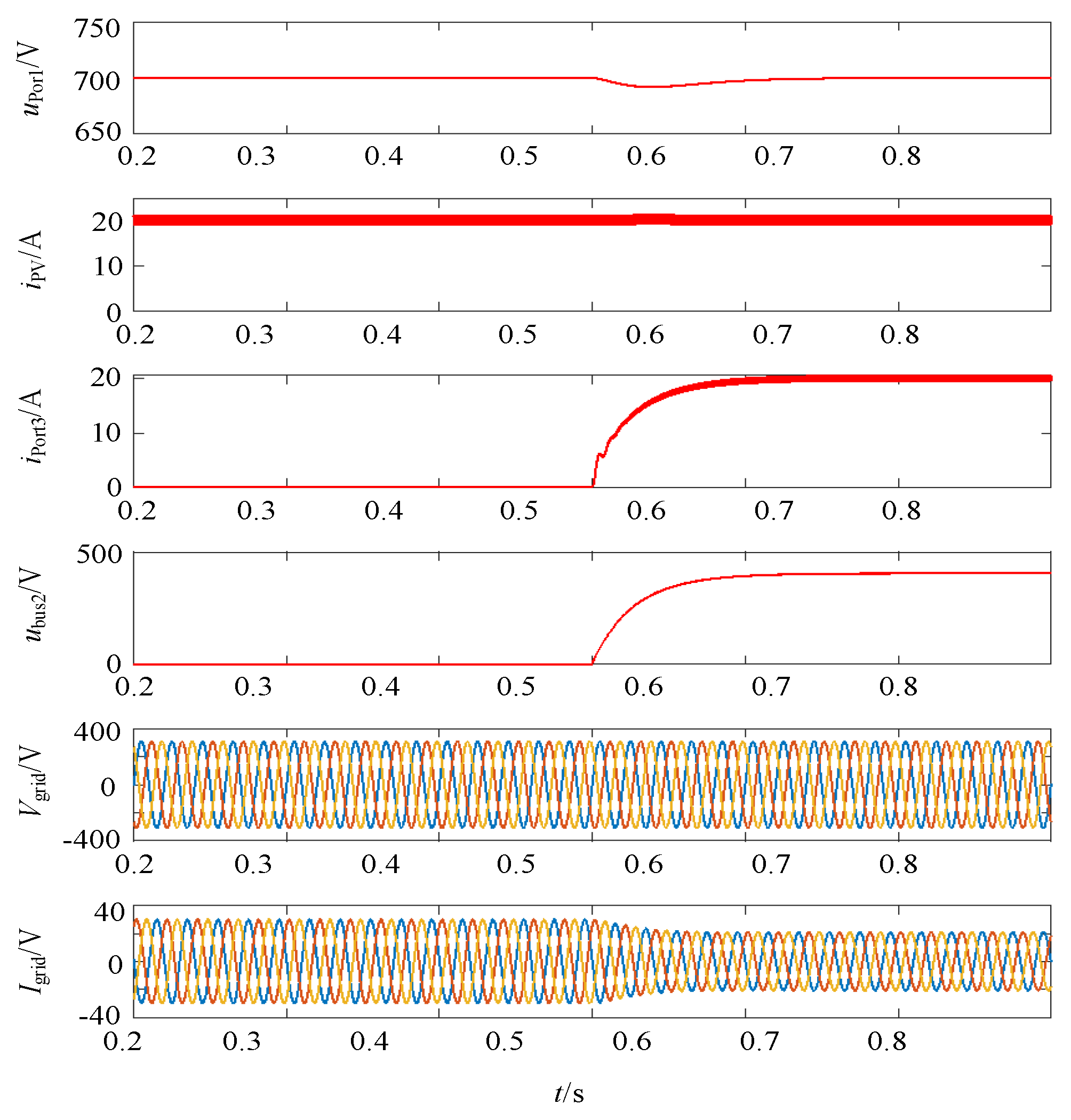
The stability of Port3 voltage uPort3 is regulated by the DC bus voltage uBus2. Under normal system operation, the voltage at Port3 is zero. When a high-voltage fault on the grid side is detected, Port3 begins to operate. At this point, within the overall system structure, the DC bus voltage uBus1 equals the sum of the Port3 voltage uPort3 and the PV output voltage uPV. While maintaining constant PV output, the reference value of uPort3 becomes an incremental variable uHVRT, increasing the voltage at Port3 so that the DC bus voltage rises to a higher level. This ensures MPPT operation of the PV module and maintains stable system performance. When the grid voltage returns to normal, uHVRT drops to zero, Port3 stops operating, and the system reverts to its stable state.
Dynamic interactions among PV MPPT, Bus-1 voltage control, Bus-2 voltage control, ESS current control, Port-3 voltage control and grid-side current control are analyzed in this subsection. In normal operation, the PV MPPT serves as an outer loop providing PV-port voltage reference, Bus-1 and Bus-2 voltage regulators stabilize intermediate bus voltages, the ESS current loop manages charging/discharging power, and the grid-side current loop regulates grid-injected power. A bandwidth-separation scheme is utilized to alleviate cross-coupling: MPPT and outer voltage loops adopt low bandwidth, while inner current loops are configured with higher bandwidth. Once HVRT mode is activated, Port-3 voltage control is assigned higher priority to elevate the DC bus voltage. MPPT remains functional with unchanged control bandwidth, and the reference signals of bus-voltage loops and grid-current loop are dynamically coordinated to prevent controller saturation. Even though partial coupling persists during HVRT transients, the bandwidth difference decouples slow outer-loop dynamics from fast inner-current responses and mitigates mutual disturbances. Bode-plot-based stability assessment demonstrates satisfactory phase margin and gain margin under both normal and HVRT conditions.
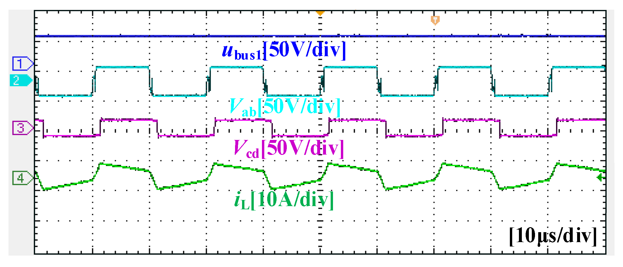
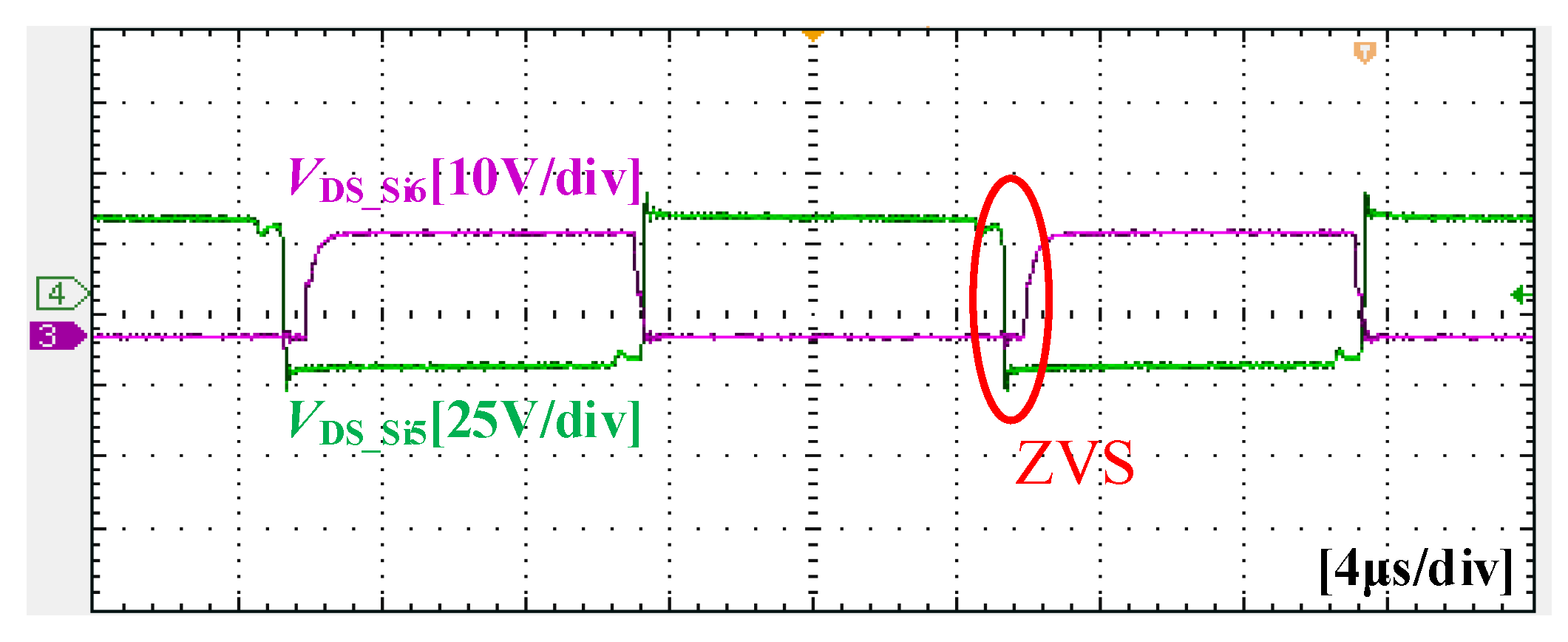
The ZVS realization of the DHB-based converter is highly dependent on the inductor current direction, phase-shift angle distribution, and load power conditions. For each bridge device, the resonant inductor current must maintain a sufficient negative commutation margin before the switch turn-on instant to completely discharge the parallel capacitor, which is the essential prerequisite for reliable ZVS achievement. Under steady-state conditions, the phase-shift ratio determines the amplitude and direction of the circulating inductor current, thereby defining the valid ZVS operating boundary. Within medium and heavy load ranges, the reactive circulating energy is adequate to guarantee full ZVS for all main switches. With the decrease of load power, the commutation current margin gradually declines, resulting in a narrowed ZVS range under light-load conditions.
As shown in
Table 2, the existing PV–ESS integrated schemes [
5,
6,
7,
8,
12,
17,
28] concentrate on energy management and normal-state power regulation without practical HVRT function. Although in the literature [
3,
27] achieve HVRT for single-stage PV systems, these solutions do not integrate energy storage and are unable to suppress photovoltaic power fluctuations. Compared with previous studies, the proposed three-port single-stage system integrates photovoltaic, energy storage and grid interfaces. It realizes energy-storage-coordinated HVRT without extra hardware, which fills the research gap between PV–storage integration and high-voltage fault ride-through.
Apart from saving two power semiconductor switches, the shared-half-bridge three-port architecture realizes simultaneous power smoothing and HVRT within one single-stage framework without auxiliary hardware circuits. The auxiliary Port3 reuses existing DHB control loops without additional independent controllers, so control complexity does not increase significantly. During voltage swell faults, the energy storage module actively modulates DC bus voltage rather than only relying on inverter-side reactive-power adjustment. It achieves millisecond-level dynamic adjustment and stronger tolerance for deep grid overvoltage events. The above quantitative performance comparison is summarized in
Table 3.
As shown in
Table 4, compared with the existing representative scheme categories, the uniqueness of this work is reflected in topology and control. On the topological level, the proposed shared-half-bridge structure reuses power devices to construct Port3 for energy storage access, without adding extra semiconductor devices. On the control level, the Port3 HVRT mechanism does not rely on additional independent controllers. Energy-management loops for normal-condition power smoothing and HVRT fault modulation are organically coupled within one unified phase-shift and duty-cycle control framework. Under grid voltage swell faults, Port3 actively adjusts the transmitted power to modulate the DC bus voltage rather than only adopting reactive-power compensation on the grid side. This coupled control realizes energy management and fault ride-through simultaneously, avoiding mode-switching oscillation that exists in many separate-control schemes.
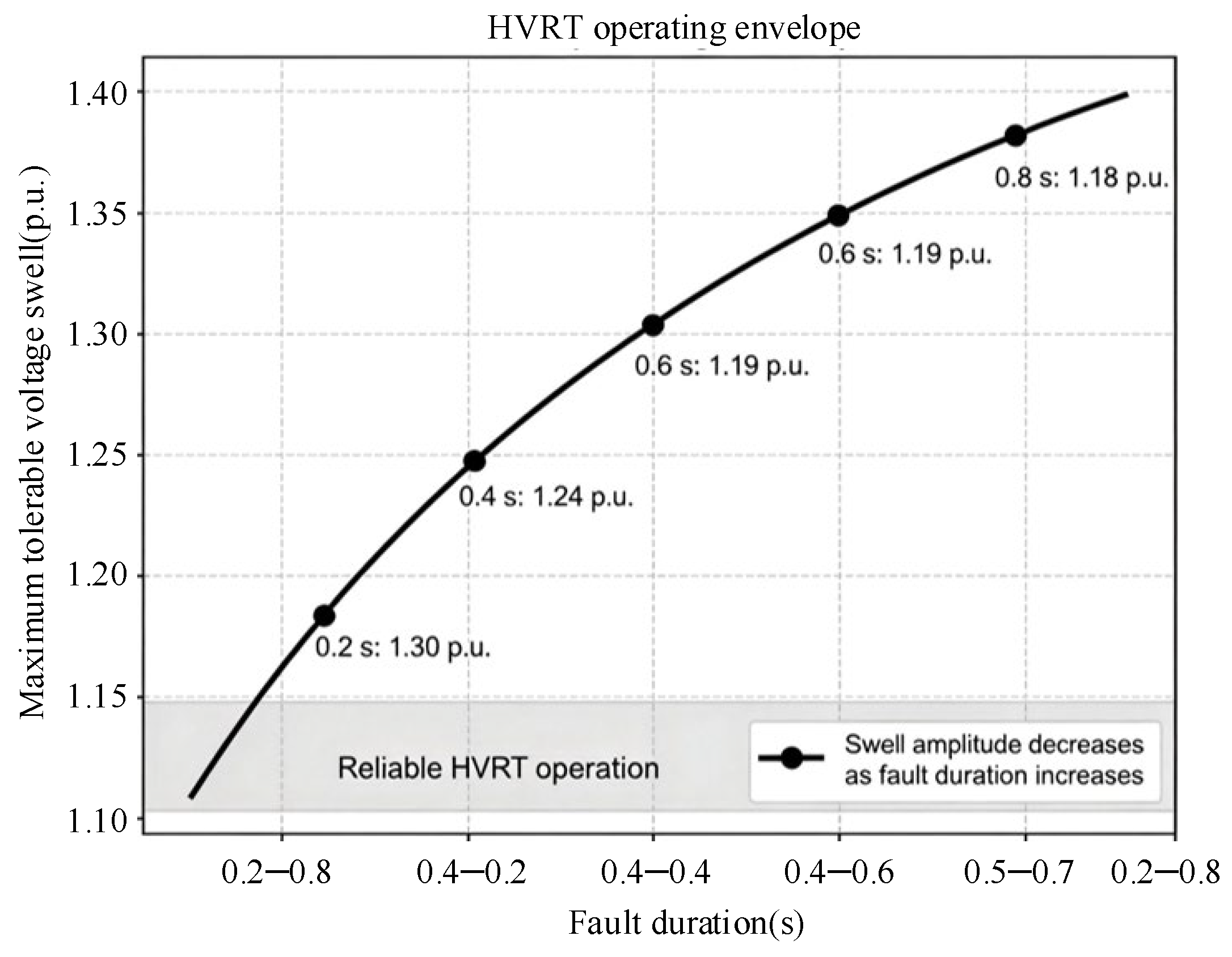
Although comprehensive ESS capacity sizing and economic optimization require long-term operational data and multi-objective scheduling algorithms, which are beyond the scope and page limit of this manuscript, the critical ESS operating boundaries for guaranteed HVRT performance are quantitatively supplemented in this section. Under grid voltage swell faults of 1.1–1.3 p.u., the ESS port provides transient power coordination, where the instantaneous regulating power ranges from 0.12 p.u. to 0.35 p.u. Within the standard fault duration of 0.1–0.8 s, the energy exchanged between the converter and ESS is limited, indicating that the proposed HVRT strategy does not rely on large-capacity energy storage.
Combined with the DHB modulation and ZVS constraints, the valid ESS operating voltage range for stable HVRT is determined as 0.6–1.1 p.u. rated voltage, and the maximum transient current stress under extreme swell faults is quantified as 1.15 p.u. In terms of SOC constraints, the proposed HVRT strategy maintains full fault-ride-through capability within the SOC range of 20–80%. When SOC is beyond this range, the ESS lacks sufficient transient charging or discharging margin, which shrinks the effective HVRT operating region and deteriorates dynamic regulation performance.