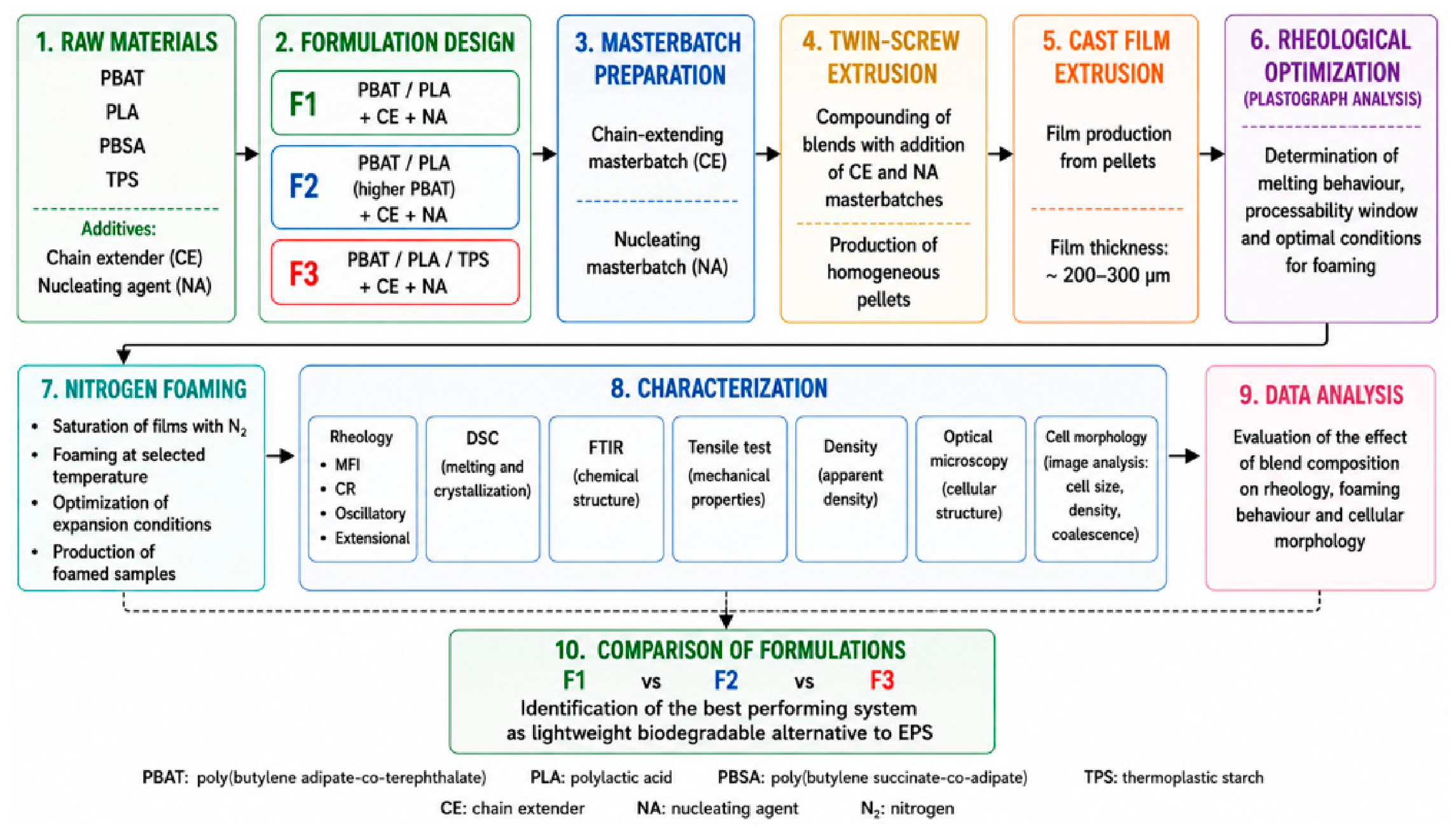
Figure 1.
Experimental workflow illustrates the preparation, processing, foaming, characterization, and comparison of the investigated biodegradable formulations.
Figure 1.
Experimental workflow illustrates the preparation, processing, foaming, characterization, and comparison of the investigated biodegradable formulations.
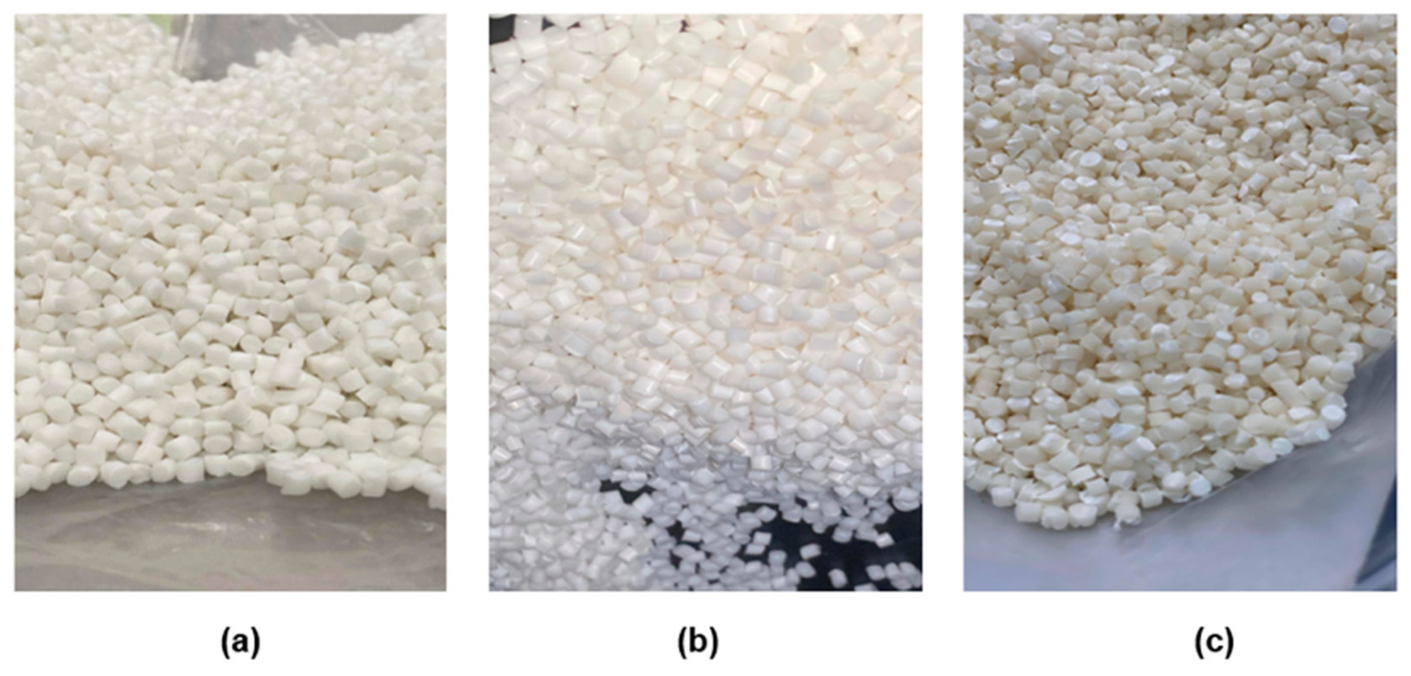
Figure 2.
Representative images of the biodegradable pellets obtained after the twin extrusion process for the investigated formulations: (a) F1, (b) F2, and (c) F3.
Figure 2.
Representative images of the biodegradable pellets obtained after the twin extrusion process for the investigated formulations: (a) F1, (b) F2, and (c) F3.
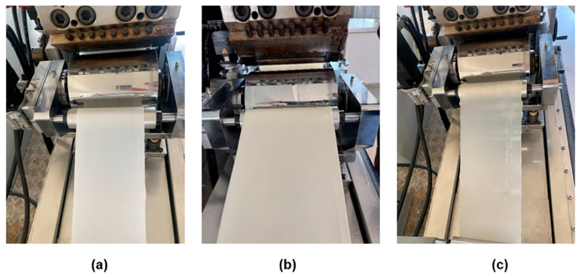
Figure 3.
Representative images of the cast extrusion process and corresponding biodegradable films obtained from the investigated formulations: (a) F1, (b) F2, and (c) F3.
Figure 3.
Representative images of the cast extrusion process and corresponding biodegradable films obtained from the investigated formulations: (a) F1, (b) F2, and (c) F3.
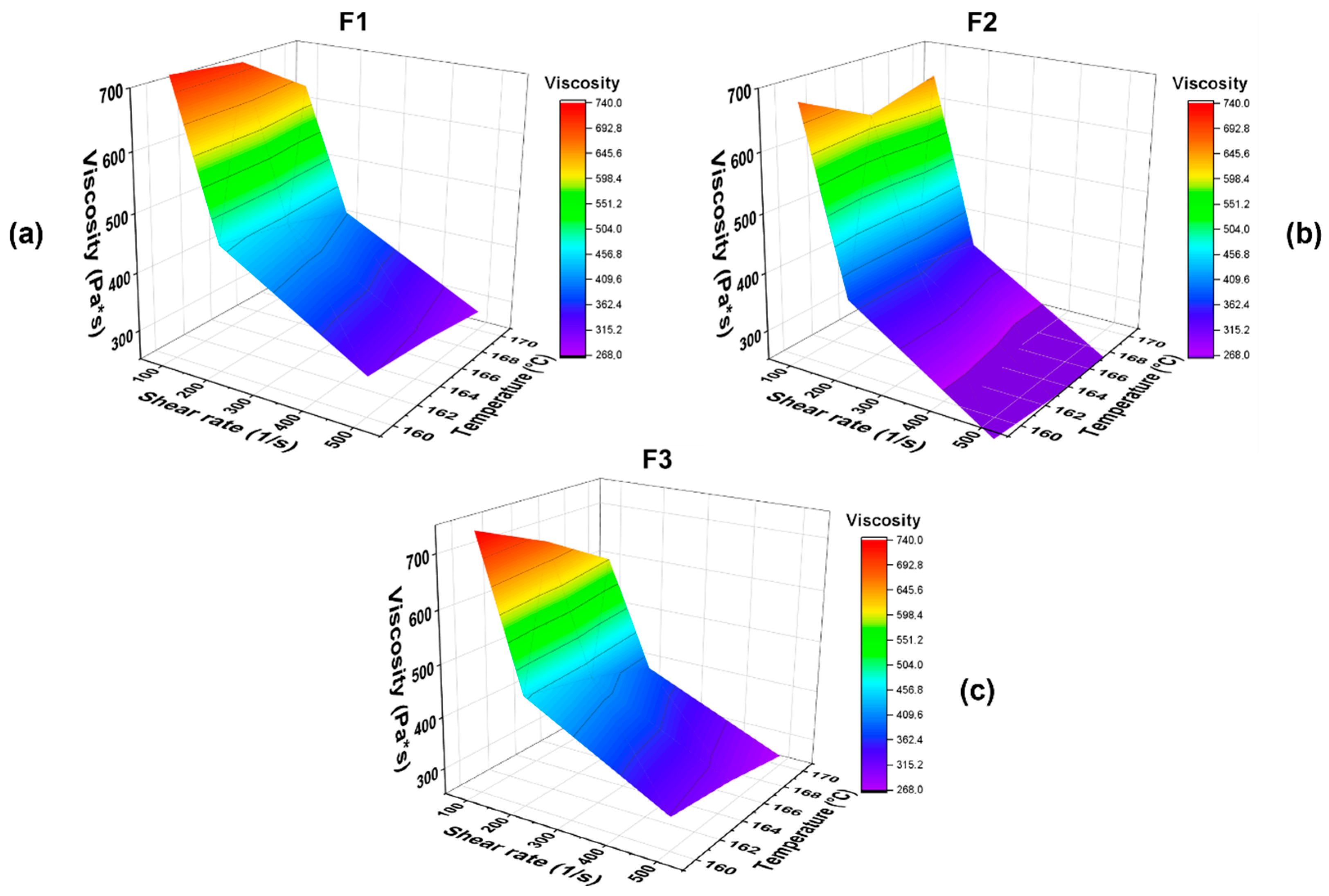
Figure 4.
Three-dimensional rheological maps showing the combined effect of shear rate and temperature on the apparent viscosity of the investigated biodegradable formulations: (a) F1, (b) F2, and (c) F3.
Figure 4.
Three-dimensional rheological maps showing the combined effect of shear rate and temperature on the apparent viscosity of the investigated biodegradable formulations: (a) F1, (b) F2, and (c) F3.
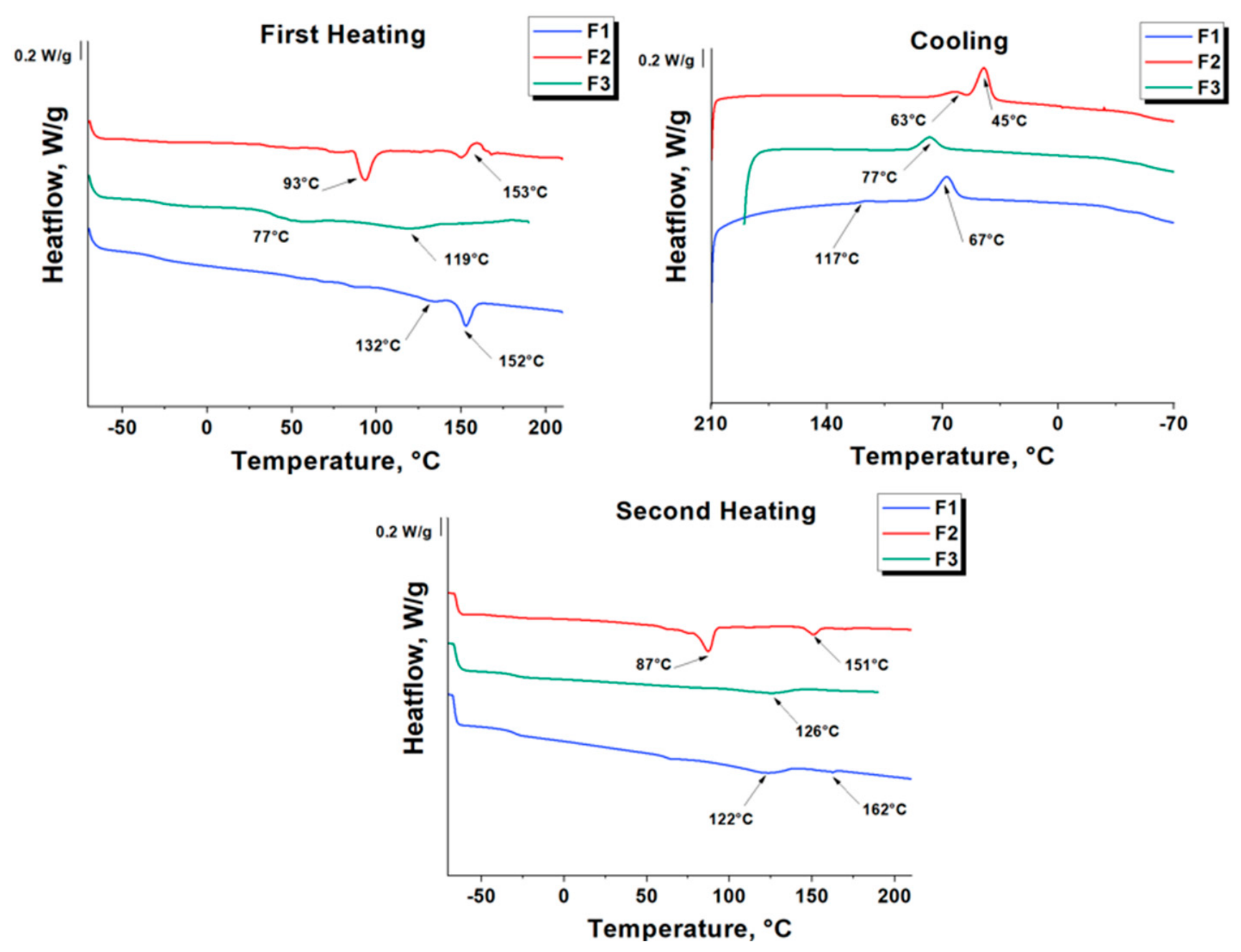
Figure 5.
DSC thermograms of the biodegradable polymer formulations F1, F2, and F3.
Figure 5.
DSC thermograms of the biodegradable polymer formulations F1, F2, and F3.
Figure 6.
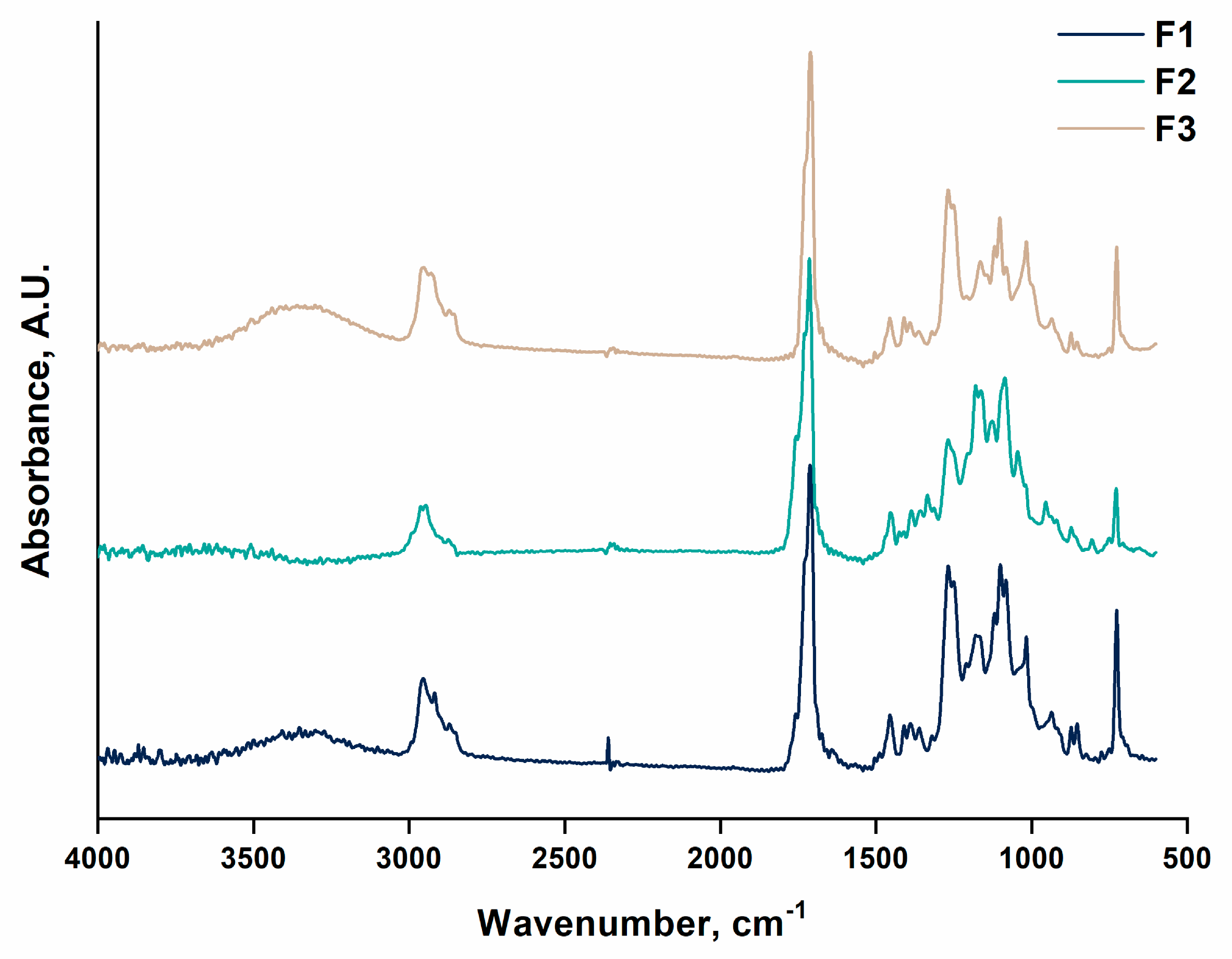
FTIR-ATR spectra of the investigated biodegradable formulations (F1, F2, and F3) acquired in the wavenumber range between 4000 and 600 cm−1.
Figure 6.
FTIR-ATR spectra of the investigated biodegradable formulations (F1, F2, and F3) acquired in the wavenumber range between 4000 and 600 cm−1.
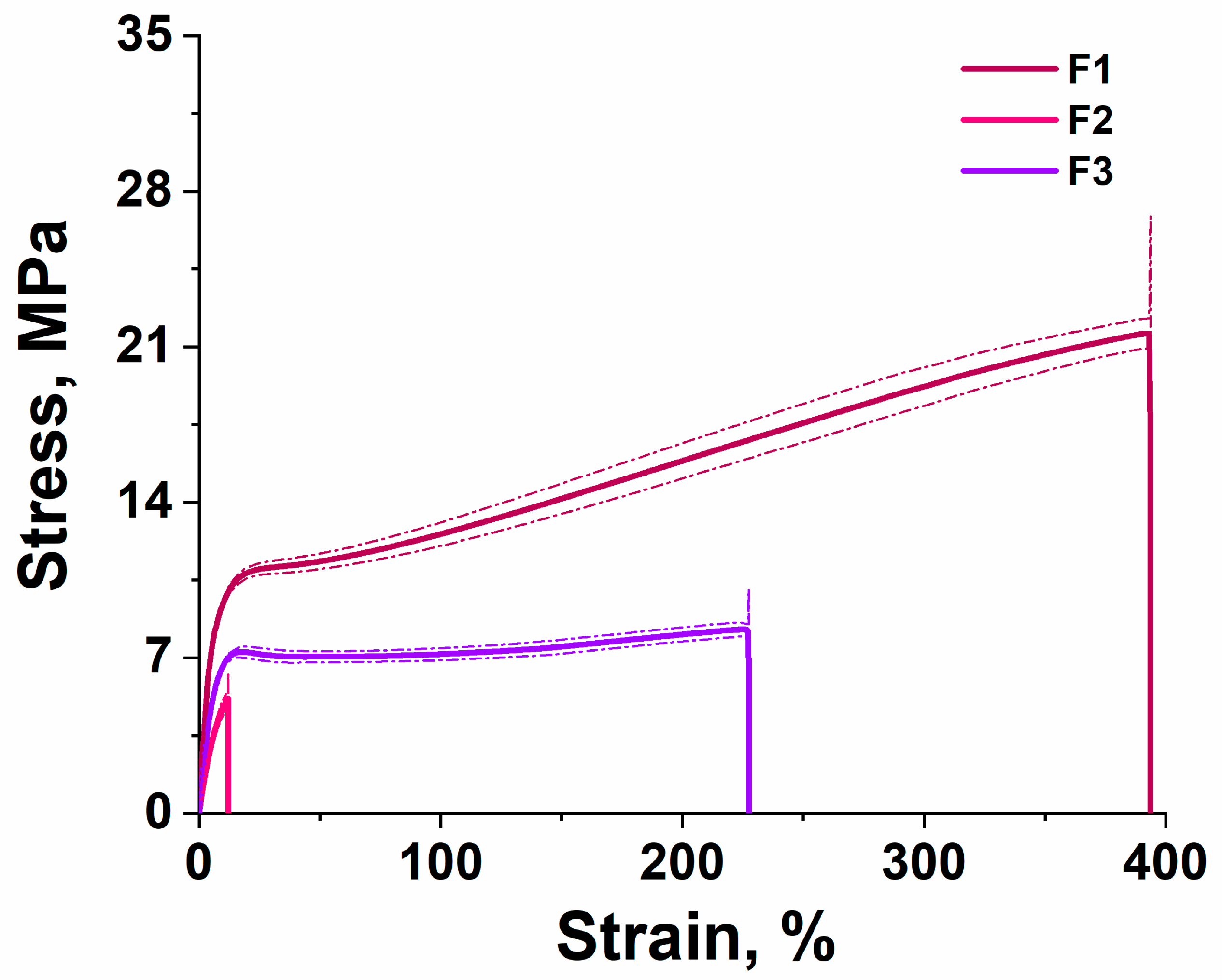
Figure 7.
Representative stress–strain curves obtained from tensile tests performed on the investigated biodegradable films: F1, F2, and F3.
Figure 7.
Representative stress–strain curves obtained from tensile tests performed on the investigated biodegradable films: F1, F2, and F3.
Figure 8.
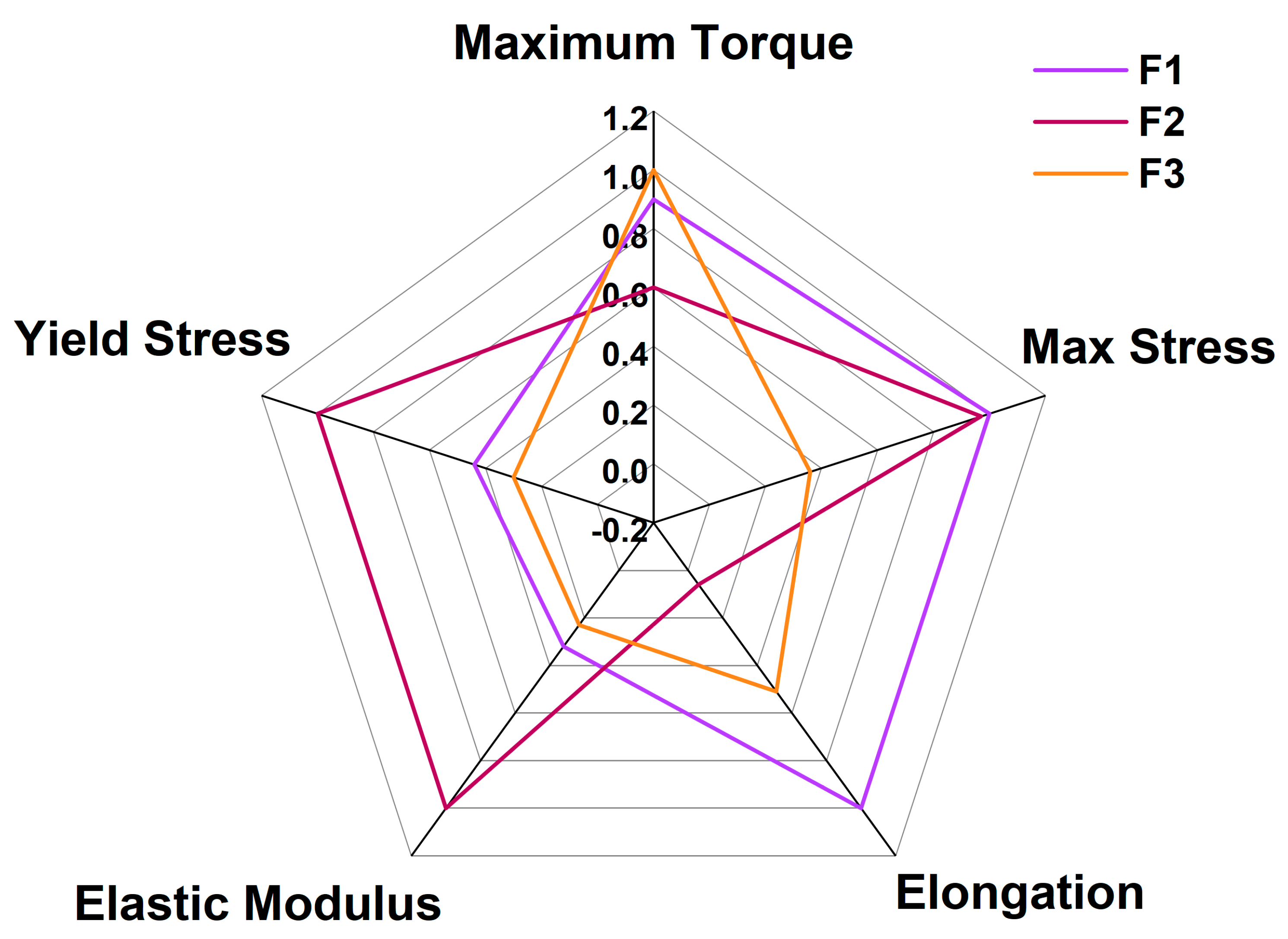
Comparative performance map showing the normalized comparison of the main rheological and mechanical properties of formulations F1, F2, and F3, including torque stability, maximum stress, elongation at break, elastic modulus, and yield stress.
Figure 8.
Comparative performance map showing the normalized comparison of the main rheological and mechanical properties of formulations F1, F2, and F3, including torque stability, maximum stress, elongation at break, elastic modulus, and yield stress.
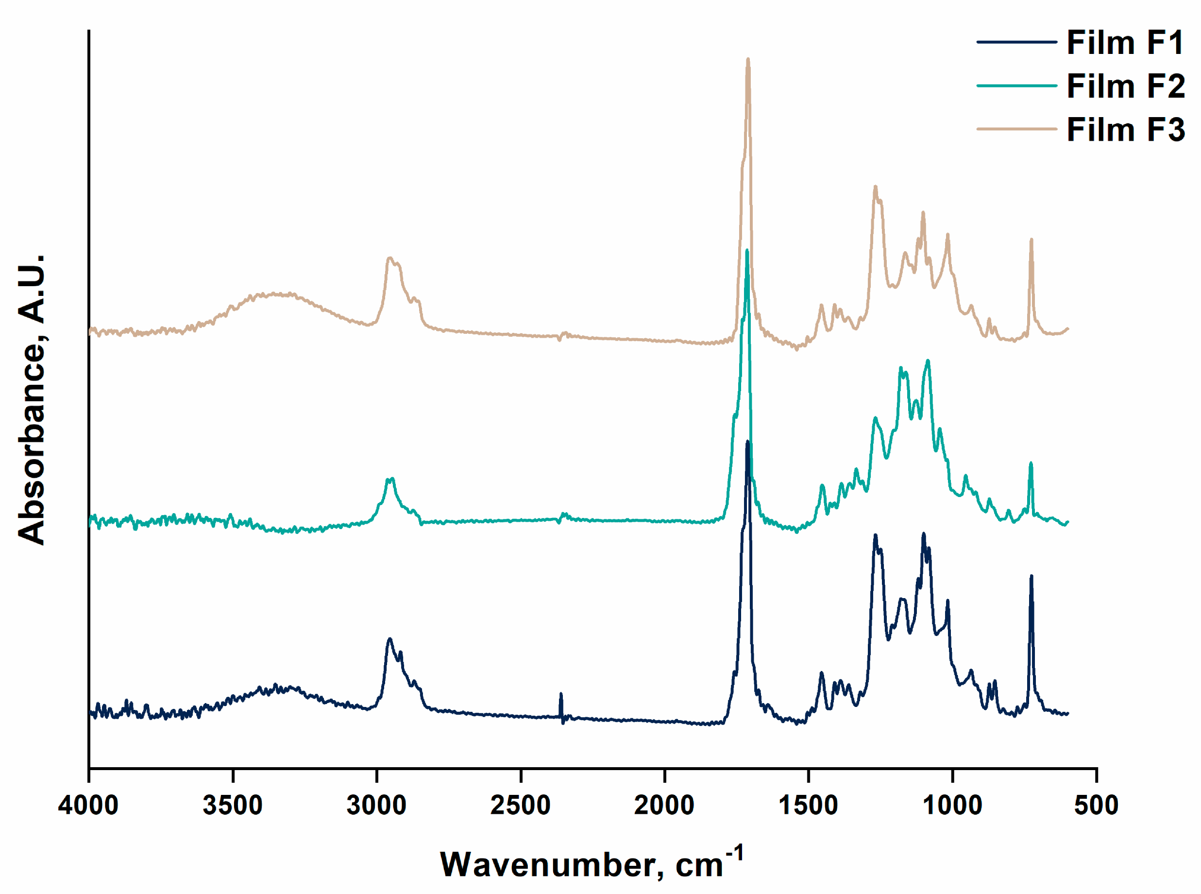
Figure 9.
FTIR-ATR spectra of the biodegradable films obtained from formulations film F1, film F2, and film F3 in the wavenumber range between 4000 and 600 cm−1.
Figure 9.
FTIR-ATR spectra of the biodegradable films obtained from formulations film F1, film F2, and film F3 in the wavenumber range between 4000 and 600 cm−1.
Figure 10.
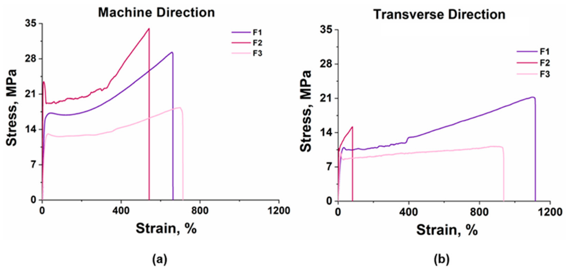
Representative stress–strain curves of the biodegradable films obtained from formulations F1, F2, and F3 tested along (a) machine direction (MD) and (b) transverse direction (TD).
Figure 10.
Representative stress–strain curves of the biodegradable films obtained from formulations F1, F2, and F3 tested along (a) machine direction (MD) and (b) transverse direction (TD).
Figure 11.
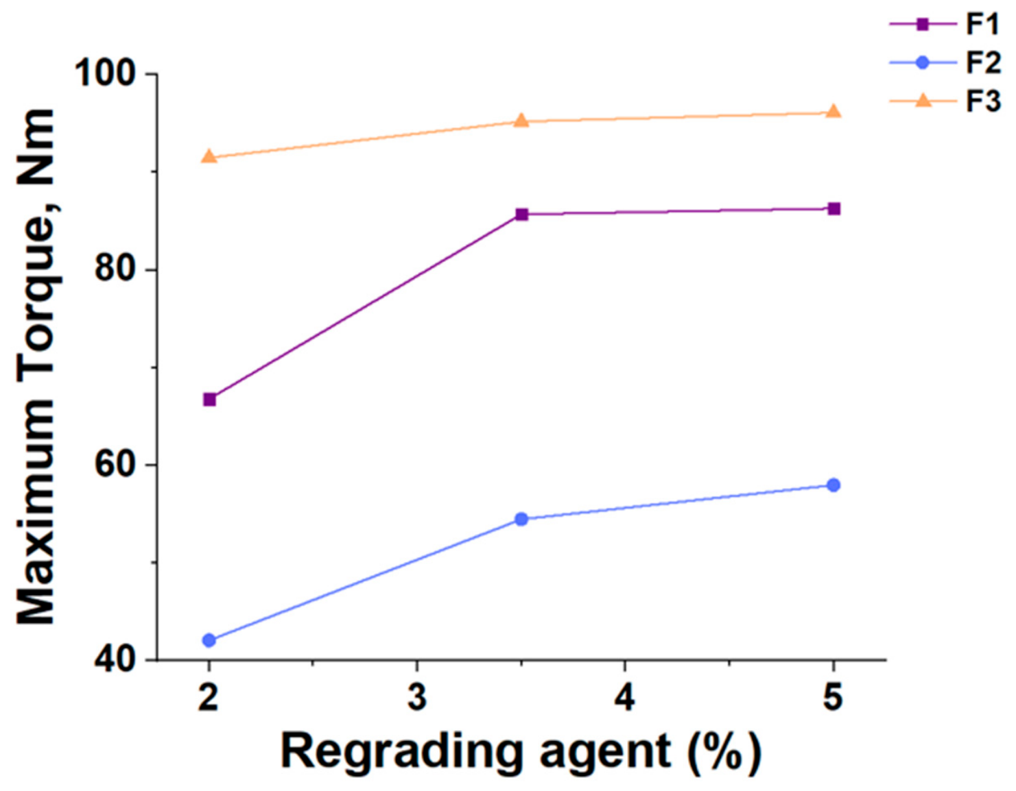
Maximum torque as a function of chain-extending agent concentration for formulations F1, F2, and F3 during melt processing.
Figure 11.
Maximum torque as a function of chain-extending agent concentration for formulations F1, F2, and F3 during melt processing.
Figure 12.
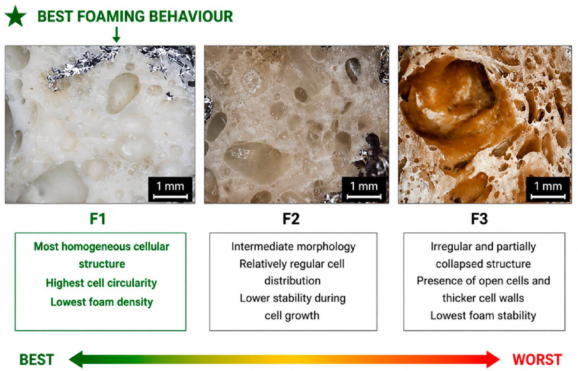
Optical microscopy images of foamed biodegradable formulations F1, F2, and F3 containing the 5 wt.% chain-extending masterbatch, acquired at approximately 20× magnification (scale bar: 1 mm).
Figure 12.
Optical microscopy images of foamed biodegradable formulations F1, F2, and F3 containing the 5 wt.% chain-extending masterbatch, acquired at approximately 20× magnification (scale bar: 1 mm).
Figure 13.
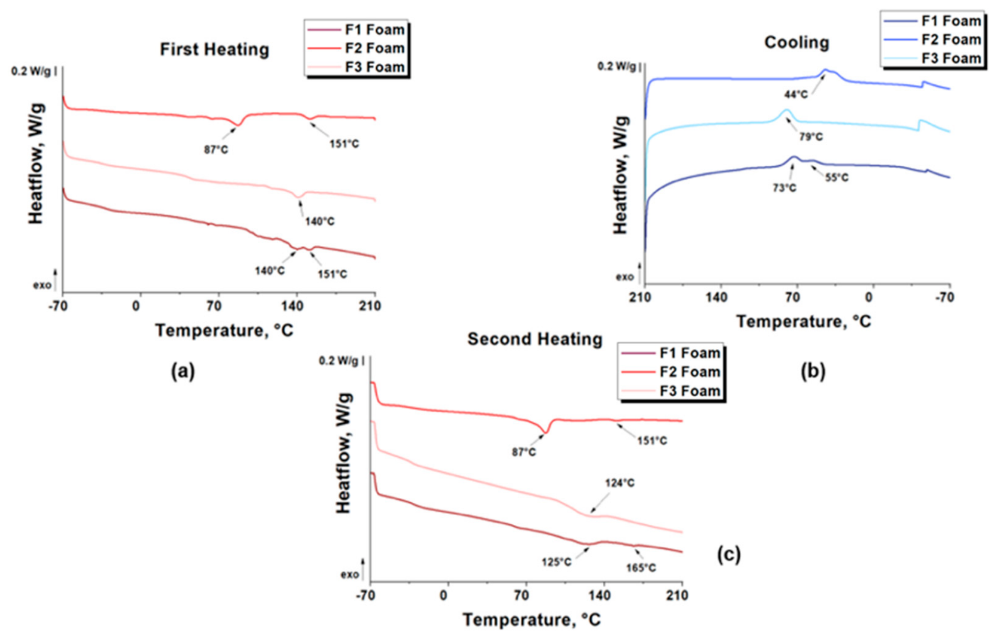
DSC thermograms of foamed biodegradable formulations F1, F2, and F3 obtained with the 5 wt.% chain-extending masterbatch during (a) first heating, (b) cooling, and (c) second heating scans.
Figure 13.
DSC thermograms of foamed biodegradable formulations F1, F2, and F3 obtained with the 5 wt.% chain-extending masterbatch during (a) first heating, (b) cooling, and (c) second heating scans.
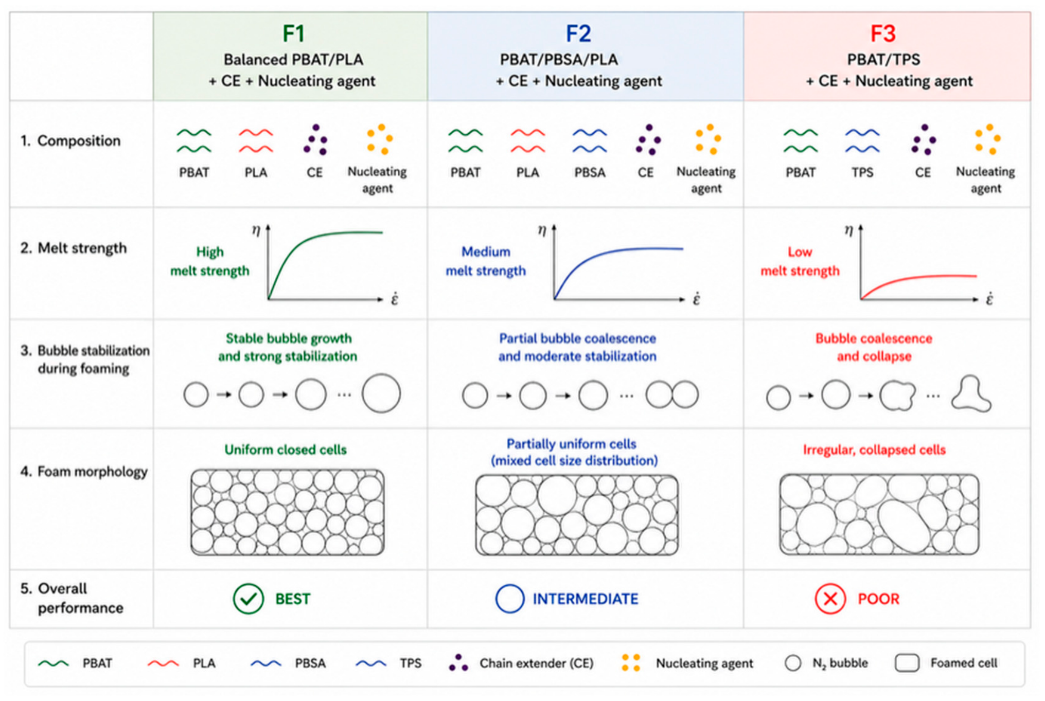
Figure 14.
Proposed mechanism of the foaming behavior of biodegradable formulations.
Figure 14.
Proposed mechanism of the foaming behavior of biodegradable formulations.
Table 1.
Composition of the investigated formulations expressed in weight percentage (wt.%).
Table 1.
Composition of the investigated formulations expressed in weight percentage (wt.%).
| Materials | F1 | F2 | F3 |
|---|
| wt.% | |
| PBAT—TH 801/2 Resin | 80 | 29.35 | 62.7 |
| PLA Ingeo Biopolymer 2003D | 18.7 | 0 | 0 |
| BioPBS FM92PM | 0 | 40 | 0 |
| PLA Luminy LX 175 | 0 | 29.35 | 0 |
| TPS—Amitroplast 8945 | 0 | 0 | 36 |
| Additive package | 1.3 | 1.3 | 1.3 |
Table 2.
Nucleating masterbatches F1, F2, and F3.
Table 2.
Nucleating masterbatches F1, F2, and F3.
| Nucleating Masterbatch F1 (%) |
|---|
| PBAT—TH 801/2 Resin | 64 |
| Nucleating additive | 20 |
| PLA Ingeo Biopolymer 2003D | 16 |
| Nucleating Masterbatch F2 (%) |
| BioPBS FM92PM | 41 |
| PBAT—TH 801/2 Resin | 19.5 |
| Nucleating additive | 20 |
| PLA Luminy LX 175 | 19.5 |
| Nucleating Masterbatch F3 (%) |
| TPS Amitroplast 8945 | 16 |
| Nucleating additive | 20 |
| PBAT—TH 801/2 Resin | 64 |
Table 3.
Chain-extending masterbatches F1, F2, and F3.
Table 3.
Chain-extending masterbatches F1, F2, and F3.
| Chain-Extending Masterbatch F1 (%) |
|---|
| Reactive additive | 10 |
| PBAT—TH 801/2 Resin | 72 |
| PLA Ingeo Biopolymer 2003D | 18 |
| Chain-Extending Masterbatch F2 (%) |
| BioPBS FM92PM | 40 |
| PBAT—TH 801/2 Resin | 25 |
| Reactive additive | 10 |
| Chain-Extending Masterbatch F3 (%) |
| TPS Amitroplast 8945 | 18 |
| Reactive additive | 10 |
| PBAT—TH 801/2 Resin | 72 |
Table 4.
Processing parameters adopted during the extrusion of formulations F1, F2, and F3, including barrel temperature profile (T1–T12), screw speed, melt temperature (Tmelt), and melt pressure (Pmelt).
Table 4.
Processing parameters adopted during the extrusion of formulations F1, F2, and F3, including barrel temperature profile (T1–T12), screw speed, melt temperature (Tmelt), and melt pressure (Pmelt).
| Machine’s Parameters |
|---|
| F1 | T1 | T2 | T3 | T4 | T5 | T6 | T7 | T8 | T9 | T10 | T11 | T12 |
| 130 | 135 | 135 | 140 | 150 | 155 | 155 | 140 | 135 | 135 | 130 | 125 |
| Screw speed (rpm) | 280 | Tmelt (°C) | 138 | | Pmelt (bar) | 25 |
| F2 | T1 | T2 | T3 | T4 | T5 | T6 | T7 | T8 | T9 | T10 | T11 | T12 |
| 120 | 140 | 145 | 150 | 155 | 155 | 160 | 155 | 150 | 145 | 145 | 145 |
| Screw speed (rpm) | 300 | Tmelt (°C) | 147 | Pmelt (bar) | 23 |
| F3 | T1 | T2 | T3 | T4 | T5 | T6 | T7 | T8 | T9 | T10 | T11 | T12 |
| 120 | 125 | 125 | 130 | 135 | 137 | 135 | 135 | 135 | 133 | 133 | 130 |
| Screw speed (rpm) | 330 | Tmelt (°C) | 129 | Pmelt (bar) | 4.7 |
Table 5.
Main processing parameters adopted during the cast extrusion process, including temperature profile, screw speed, haul-off speed, calender speed, and winding conditions, for Formulation 1.
Table 5.
Main processing parameters adopted during the cast extrusion process, including temperature profile, screw speed, haul-off speed, calender speed, and winding conditions, for Formulation 1.
| Parameter | Value | Unit |
|---|
| Cylinder temperature | 155–160 | °C |
| Die/head temperature | 144–145 | °C |
| Extruder screw speed | 70 | rpm |
| Haul-off speed | 1.6 | m/min |
| Calender speed | 1.2–1.3 | m/min |
| Winding setting | 40 | % |
Table 6.
Main processing parameters adopted during the cast extrusion process, including temperature profile, screw speed, haul-off speed, calender speed, and winding conditions, for Formulation 2.
Table 6.
Main processing parameters adopted during the cast extrusion process, including temperature profile, screw speed, haul-off speed, calender speed, and winding conditions, for Formulation 2.
| Parameter | Value | Unit |
|---|
| Cylinder temperature | 159–160 | °C |
| Die/head temperature | 164–165 | °C |
| Extruder screw speed | 99.9–100 | rpm |
| Haul-off speed | 0.7–0.8 | m/min |
| Calender speed | 0.7–0.8 | m/min |
| Winding setting | 15–16 | % |
Table 7.
Main processing parameters adopted during the cast extrusion process, including temperature profile, screw speed, haul-off speed, calender speed, and winding conditions, for Formulation 3.
Table 7.
Main processing parameters adopted during the cast extrusion process, including temperature profile, screw speed, haul-off speed, calender speed, and winding conditions, for Formulation 3.
| Parameter | Value | Unit |
|---|
| Cylinder temperature | 154–164 | °C |
| Die/head temperature | 147–150 | °C |
| Extruder screw speed | 75 | rpm |
| Haul-off speed | 1.4 | m/min |
| Calender speed | 1.1–1.2 | m/min |
| Winding setting | 40 | % |
Table 8.
Symbols, descriptions and units used for the calculation of the degree of crystallinity from DSC thermograms.
Table 8.
Symbols, descriptions and units used for the calculation of the degree of crystallinity from DSC thermograms.
| Symbol | Description | Unit |
|---|
| Melting enthalpy of polymer i measured during the DSC heating scan | J/g |
| Cold crystallization enthalpy of polymer i | J/g |
| Melting enthalpy of 100% crystalline polymer i | J/g |
| Weight fraction of polymer i in the formulation | - |
| Degree of crystallinity | % |
Table 9.
Experimental design adopted in the present study.
Table 9.
Experimental design adopted in the present study.
| Category | Investigated Parameter | F1 | F2 | F3 |
|---|
| Independent variable | Blend composition | PBAT/PLA | PBAT/PBSA/PLA | PBAT/TPS |
| Controlled variable | Nucleating masterbatch content | 5 wt.% | 5 wt.% | 5 wt.% |
| Controlled variable | Chain-extending masterbatch content (foaming stage) | 5 wt.% | 5 wt.% | 5 wt.% |
| Controlled variable | Foaming temperature | 165 °C | 165 °C | 165 °C |
| Controlled variable | Saturation pressure | Same conditions | Same conditions | Same conditions |
| Controlled variable | Saturation time | 1 h | 1 h | 1 h |
| Controlled variable | Depressurization procedure | Identical | Identical | Identical |
| Response variables | Measured properties | Rheological, thermal,
mechanical and
morphological | Rheological, thermal,
mechanical and
morphological | Rheological, thermal,
mechanical and
morphological |
Table 10.
Melt flow index (MFI) values of the investigated biodegradable compounds measured under standard testing conditions.
Table 10.
Melt flow index (MFI) values of the investigated biodegradable compounds measured under standard testing conditions.
| Compound | g/10 min |
|---|
| F1 | 3.56 ± 0.10 c |
| F2 | 5.42 ± 0.10 a |
| F3 | 4.36 ± 0.28 b |
Table 11.
Thermal parameters obtained from DSC analyses of the investigated biodegradable formulations (F1, F2, and F3).
Table 11.
Thermal parameters obtained from DSC analyses of the investigated biodegradable formulations (F1, F2, and F3).
| | First Heating | Second Heating | Cooling |
|---|
| | Tm (°C) | Xc (%) | Tg(°C) | Tm (°C) | Xc (%) | Tg(°C) | Tc (°C) |
|---|
| F1 | 132 (PBAT) | 7.37 ± 0.5 | −69 | 122 | 5.65 ± 0.2 | −36 | 67 |
| 152 (PLA) | 15.3 ± 0.5 | 75 | 162 | 11.7 ± 0.3 | 59 | 117 |
| F2 | 93 (PBSA) | 14.7 ± 0.3 | | 87 | 8.8 ± 0.7 | −41.52 | 45 |
| 150 (PLA) | 11.1 ± 0.5 | | 151 | 9.3 ± 0.4 | 63 |
| F3 | 119 | 6.25 ± 0.2 | −34 | 126 | 4.33 ± 0.3 | −34 | 77 |
Table 12.
Tensile properties of the investigated biodegradable film formulations including maximum stress, elongation at break, elastic modulus and yielding stress. Values are reported as mean ± standard deviation.
Table 12.
Tensile properties of the investigated biodegradable film formulations including maximum stress, elongation at break, elastic modulus and yielding stress. Values are reported as mean ± standard deviation.
| Name | Max Stress. MPa | Max Strain. % | Elastic Modulus. MPa | Yielding Stress. MPa |
|---|
| F1 | 22.7 ± 0.5 a | 454 ± 43 a | 206 ± 18 b | 7.2 ± 0.3 b |
| F2 | 22.1 ± 1.0 a | 26.5 ± 6.3 c | 643 ± 28 a | 16.5 ± 0.9 a |
| F3 | 8.3 ± 0.3 b | 233 ± 5 b | 145 ± 14 c | 5.0 ± 0.2 c |
Table 13.
Comparison of the MD film parameters of F1, F2, and F3.
Table 13.
Comparison of the MD film parameters of F1, F2, and F3.
| | Max Stress, MPa | Max Strain, % | Elastic Modulus, MPa | Yielding Stress, MPa |
|---|
| F1 | 25.9 ± 3.4 b | 772 ± 114 a | 224 ± 12 b | 14.2 ± 0.8 b |
| F2 | 36.1 ± 3.5 a | 560 ± 45 b | 843 ± 38 a | 23.9 ± 1.3 a |
| F3 | 14.1 ± 2.6 c | 672 ± 61 ab | 105 ± 12 c | 8.4 ± 1.0 c |
Table 14.
Comparison of the TD film parameters of F1, F2, and F3.
Table 14.
Comparison of the TD film parameters of F1, F2, and F3.
| | Max Stress, MPa | Max Strain, % | Elastic Modulus, MPa | Yielding Stress, MPa |
|---|
| F1 | 19.3 ± 1.5 a | 985 ± 116 a | 89 ± 3 c | 7.5 ± 0.3 b |
| F2 | 13.5 ± 2.7 b | 86.6 ± 12.5 c | 694 ± 104 a | 9.4 ± 2.3 a |
| F3 | 10.4 ± 0.9 c | 647 ± 307 b | 130 ± 14 b | 8.3 ± 0.6 ab |
Table 15.
Maximum torque for formulation F1 containing different concentrations of chain-extending agent during melt processing at constant temperature.
Table 15.
Maximum torque for formulation F1 containing different concentrations of chain-extending agent during melt processing at constant temperature.
| Formulation | Chain-Extending
Agent (%) | Maximum Torque (Nm) |
|---|
| F1 | 2 | 66.8 ± 0.7 |
| F1 | 3.5 | 85.7 ± 0.8 |
| F1 | 5 | 86.3 ± 0.6 |
Table 16.
Maximum torque for formulation F2 containing different concentrations of chain-extending agent during melt processing at constant temperature.
Table 16.
Maximum torque for formulation F2 containing different concentrations of chain-extending agent during melt processing at constant temperature.
| Formulation | Chain-Extending
Agent (%) | Maximum Torque (Nm) |
|---|
| F2 | 2 | 42.1 ± 0.9 |
| F2 | 3.5 | 54.5 ± 0.8 |
| F2 | 5 | 58 ± 0.7 |
Table 17.
Maximum torque for formulation F3 containing different concentrations of chain extender agent during melt processing at constant temperature.
Table 17.
Maximum torque for formulation F3 containing different concentrations of chain extender agent during melt processing at constant temperature.
| Formulation | Chain-Extending
Agent (%) | Maximum Torque (Nm) |
|---|
| F3 | 2 | 91.5 ± 0.8 |
| F3 | 3.5 | 95.2 ± 0.9 |
| F3 | 5 | 96.1 ± 0.7 |
Table 18.
Density of foam for formulations F1, F2, and F3.
Table 18.
Density of foam for formulations F1, F2, and F3.
| Sample | Value (g/cm3) |
|---|
| F1 foam | 0.786 ± 0.02 |
| F2 foam | 0.89 ± 0.03 |
| F3 foam | 1.05 ± 0.04 |
Table 19.
Quantitative morphological parameters of the foamed structures obtained by ImageJ image analysis.
Table 19.
Quantitative morphological parameters of the foamed structures obtained by ImageJ image analysis.
| Parameter | Unit | F1 | F2 | F3 |
|---|
| Number of analyzed cells | – | 40 | 40 | 40 |
| Equivalent cell diameter | µm | 4.00 ± 0.29 | 4.89± 0.19 | 6.35 ± 0.42 |
| Median equivalent cell diameter | µm | 1.95 | 2.97 | 5.05 |
| Circularity | – | 0.826 ± 0.04 | 0.701 ± 0.05 | 0.563 ± 0.06 |
| Average cell area | µm2 | 12.55 ± 1.8 | 18.74 ± 2.5 | 31.68 ± 4.2 |
| Two-dimensional areal cell density | cells/mm2 | 5.060 | 6.094 | 7.756 |
| Apparent porosity | % | 6.35 ± 0.7 | 11.42 ± 1.1 | 24.57 ± 2.3 |
Table 20.
Comparison of the physical and cellular morphology parameters of the developed biodegradable foams (F1–F3) and typical values reported for commercial expanded polystyrene (EPS).
Table 20.
Comparison of the physical and cellular morphology parameters of the developed biodegradable foams (F1–F3) and typical values reported for commercial expanded polystyrene (EPS).
| Parameter | F1 | F2 | F3 | Commercial EPS |
|---|
| Density (g/cm3) | 0.786 ± 0.02 | 0.89 ± 0.03 | 1.05 ± 0.04 | 0.010–0.020 |
| Average cell area (µm2) | 12.55 ± 1.8 | 18.74 ± 2.5 | 31.68 ± 4.2 | — |
| Equivalent cell diameter (µm) | 4.00 ± 0.29 | 4.89 ± 0.19 | 6.35 ± 0.42 | 50–200 |
| Porosity (%) | 6.35 ± 0.7 | 11.42 ± 1.1 | 24.57 ± 2.3 | >95 |
| Circularity | 0.826 ± 0.04 | 0.701 ± 0.05 | 0.563 ± 0.06 | ~0.9 (closed cells) |
| Predominant cell structure | Predominantly regular cells | Intermediate/partially irregular cells | Irregular and partially collapsed cells | Closed, uniform |
Table 21.
Thermal analysis parameters of foam formulations F1, F2, and F3.
Table 21.
Thermal analysis parameters of foam formulations F1, F2, and F3.
| | First Heating | Second Heating | Cooling |
|---|
| | Tm (°C) | Tm (°C) | Tc (°C) |
| F1 | 140 (PBAT) | 125 | 55 |
| 151 (PLA) | 165 | 73 |
| F2 | 87 (PBS) | 87 | 44 |
| 151 (PLA) | 151 |
| F3 | 140 | 124 | 79 |