Article

Hybridisation of District Heating in Existing Office Buildings Using Air-to-Water Heat Pumps: A Case Study on Energy and Performance

Department of Civil and Building Services Engineering, Polytechnic University of Timisoara, Piata Victoriei, No. 2A, 300006 Timisoara, Romania
*
Author to whom correspondence should be addressed.
Sustainability 2026, 18(10), 4965; https://doi.org/10.3390/su18104965
Submission received: 17 April 2026 / Revised: 11 May 2026 / Accepted: 12 May 2026 / Published: 15 May 2026

Abstract

This study investigates integrating an air-to-water heat pump (HP) into an existing office building served by a district heating (DH) system to improve energy performance and reduce environmental impact. The system was modelled using Polysun software, considering two operating scenarios: a conventional configuration based solely on DH and a hybrid configuration combining DH with a HP. The analysis was performed using hourly simulations over a typical meteorological year, allowing a detailed evaluation of system behaviour under varying climatic conditions. The results indicate that the hybrid system reduces total energy consumption by approximately 24%, while natural gas consumption decreases by about 36%. Although electricity consumption increases due to HP operation, the overall energy performance is significantly improved. The HP operates efficiently within the analysed temperature range, with COP values ranging from 1.8 to 3.0 and a seasonal performance coefficient of approximately 3.6. The system ensures full coverage of the heating demand, with a negligible deficit, confirming appropriate sizing and control strategy. From an environmental perspective, the hybrid configuration results in approximately 29 t CO2 per year less than the conventional system. These results demonstrate that integrating HPs into existing DH systems can represent a viable solution for similar buildings under comparable operating conditions. Beyond the quantified energy and environmental benefits, the novelty of the study lies in evaluating a hybrid solution under real operating conditions affected by DH instability. The results highlight practical implications for system resilience, operational flexibility, and the applicability of this retrofit strategy to existing buildings connected to conventional DH networks.

1. Introduction

1.1. Context and Literature Review

Due to rising greenhouse gas (GHG) emissions, climate change and global warming are the world’s biggest concerns of the twenty-first century, with carbon dioxide (CO2) as the major contributor, accounting for 39% of GHG emissions in the construction sector [1]. In the European Union (EU), over 75% of the built stock is considered energy inefficient [2], and about 46% of the energy used in buildings is related to heating, cooling, and domestic hot water (DHW) [3]. Therefore, cutting building energy use and CO2 emissions is essential to stopping global warming [4,5]. In this context, the transition toward sustainable heating solutions is essential for achieving long-term decarbonisation targets [6].
District heating (DH) systems play an important role in this transition, as they enable the efficient supply of thermal energy at a large scale while facilitating the implementation of renewable energy sources (RES). The integration of renewable energy into low-temperature DH systems has been addressed in recent studies, highlighting their potential to improve energy performance and reduce environmental impact [7]. However, in many countries, particularly in Eastern Europe, existing DH systems face significant challenges, including high distribution losses, low efficiency, and supply instability [8].
We need to significantly reduce existing emissions and counter the rising trend in CO2 emissions driven by population growth to meet the 2050 neutrality targets. This can be achieved 70% through increasing the electrification of the thermal sector through heat pumps (HPs) and implementing highly energy-efficient technologies, and the remaining 30% through DH and other renewable sources (photovoltaic, wind, geothermal) [1,9]. The development of high-temperature HPs enables their integration into existing systems and adaptation to building requirements [10].
As to [1], by 2050, more than 85% of buildings will be prepared for zero-carbon status, resulting in a 75% decrease in heating intensity, with around 50% covered by HPs and 10% by DH.
For the 2025–2026 period, the EU is preparing a new Heating and Cooling Strategy, focusing on energy system integration, the development of renewable-based DH networks, and the utilisation of waste heat. At the same time, European policies promote local heat planning, with approximately 1500 cities expected to develop heating and cooling plans in the coming years, supporting the transition toward decarbonised DH systems [11]. In Romania, DH systems are highly inefficient due to several issues across the production, transportation, and distribution chain, compounded by the lack of rehabilitation and modernisation initiatives to enhance their energy and economic efficiency.
Despite the energy efficiency of HP technology, including air-source heat pumps (ASHPs), it still necessitates electrical energy. ASHPs use renewable energy, offering a unique combination of mature technology, economic viability, and environmental compatibility, which aligns with long-term decarbonisation objectives and has found worldwide applications [11]. It is projected that large-scale HP will account for over 50% of the DH in 2050. At least in terms of CO2 emissions, this will make HP considerably more competitive than current DH [12]. The DH energy load and temperature are affected differently by each HP combination in the DH network. As a result, HP will affect building energy demand, the DH network, and the electrical grid, leading to strong interactions among these components. This suggests that the DH-HP-Building system will be dependent on power prices [13].
However, most existing studies rely on theoretical analyses or large-scale models and pay limited attention to real-world implementation under operating conditions, particularly in existing buildings connected to unstable DH systems.
In this context, this article addresses the solution to enhance the performance of the DH system to which an existing office building in Timisoara, Romania, is connected by implementing an air-to-water HP for heating, illustrated through a case study. The study was conducted following multiple failures in the DH company’s thermal energy distribution system and prolonged interruptions in thermal energy supply. The analysis is based on real operational data and considers multiple operating scenarios. The novelty of this article lies in the investigation of a real case study characterised by intermittent DH operation, in which the HP system is used not only to improve energy efficiency but also to ensure the continuity of heat supply.

1.2. Research Gap and Objective

Although the integration of HPs into DH systems has been extensively investigated in the literature, most existing studies focus on theoretical analyses, optimisation models, or large-scale energy system assessments [8,10,14]. While these approaches provide valuable insights into system performance, they do not fully capture the real operating conditions of existing buildings connected to conventional DH systems.
Previous studies have mainly investigated HP integration in DH systems through optimisation models, low-temperature network analyses, or large-scale energy planning approaches, often focusing on energy savings and decarbonisation potential [15]. Empirical studies addressing building-level hybridisation under real operating constraints remain comparatively limited, particularly for existing buildings connected to unstable DH networks that are subject to supply interruptions and temperature variability [16]. Moreover, previous studies rarely assess energy performance, operational resilience, and supply continuity simultaneously under such conditions. This gap motivates this study.
In particular, recent studies on the integration of RES into low-temperature DH systems highlight their significant potential to enhance energy performance and reduce carbon emissions [7]. However, there is still a lack of research addressing the practical implementation of HPs in existing buildings located in areas where operational instability, high distribution losses, and intermittent heat supply characterise DH systems.
Under such conditions, theoretical solutions cannot be directly applied, and performance evaluation is needed under real operating conditions, accounting for temperature variations, operating regimes, and interactions among different energy sources.
In this context, the present study aims to contribute to bridging this gap by analysing a real case of integrating an air-to-water HP into an existing building connected to a DH system. The study is based on real operational data and considers multiple operating scenarios, reflecting actual operating conditions. The main objective is to evaluate the impact on energy performance, operational reliability, and the overall sustainability of the heating system.

1.3. Novelty and Contribution

Beyond energy savings assessment, the novelty of this study lies in evaluating hybridisation under real DH instability conditions, explicitly considering operational resilience and continuity of heat supply as part of system performance. Furthermore, the study proposes a reproducible framework applicable to similar existing buildings connected to conventional DH systems. Table 1 shows the positioning of the present study relative to the literature.
The following are this study’s primary contributions:
  • Analysis of the performance of a hybrid system combining DH and an air-to-water HP under real operating conditions;
  • Evaluation of operational reliability in the context of an unstable DH system;
  • Comparison of multiple operating scenarios for system optimisation;
  • Highlighting the role of HPs in increasing the resilience of heating systems;
  • Providing practical insights for the integration of air-to-water HP in existing buildings connected to DH systems.

2. Theoretical Background and Technological Context

2.1. District Heating Systems

2.1.1. General Characteristics

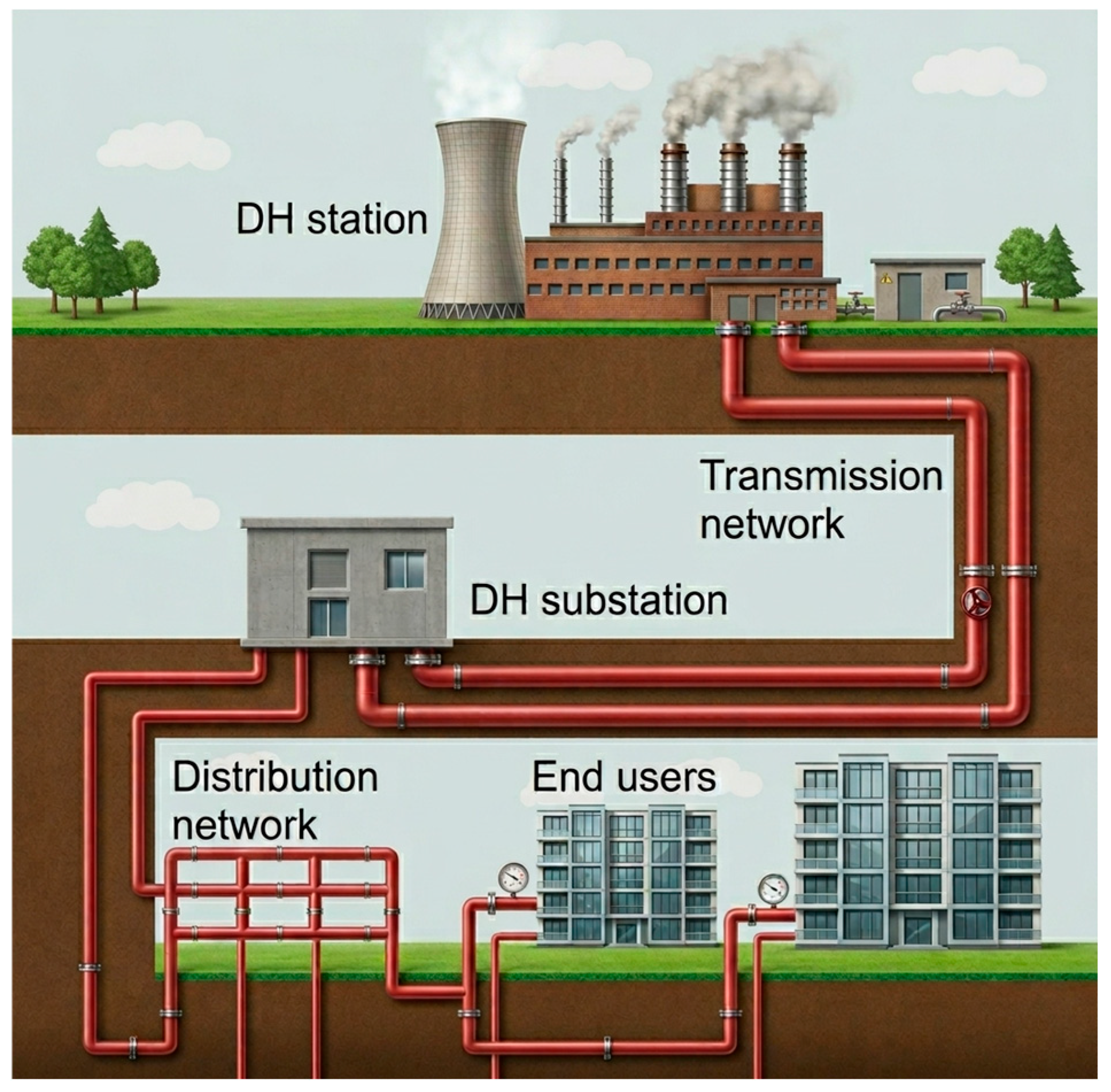
DH systems are centralised solutions for the production and distribution of thermal energy to consumers and are widely used in urban areas (Figure 1). These systems provide space heating and DHW through a network of pipelines that transport the heat carrier from the production source to end users [7].
DHs are always changing [17]. Steam distribution through concrete pipes was the basis for the first generation of DH (1880s), pressurised hot water over 100 °C in concrete pipes for the second generation (1930s), pressurised hot water below 100 °C in prefabricated insulated pipes for the third generation (1980s), and low-temperature DH for the fourth and fifth generations. A low-temperature (50–70 °C) or ultra-low-temperature (35–45 °C) DH network is the term used to describe the fourth DH generation [18,19].
The fifth-generation DHC network is referred to as the ambient ground temperature (less than 35 °C) DHC network [20,21]. This system’s capacity to deliver heating and cooling services via a single network by reversing the direction of water flow at user terminals is one of its primary features. The widespread use of distributed HPs that can operate in both heating and cooling modes enables this inversion. By employing decentralised HPs, these systems significantly lower supply and return temperatures.
Lowering the DH’s working temperature promotes the incorporation of distributed low-temperature waste and renewable heat sources as well as increased efficiency (i.e., decreased heat losses). Geothermal energy, solar energy, heat from burning biomass, industrial waste heat, combined heat and power (CHP), waste incineration, and other energy sources can all be efficiently utilised thanks to DH [8,22]. Furthermore, modern DH systems (4th and 5th generations) are designed to operate at lower temperatures, enabling efficient integration of HP technologies [18].
The average contribution of renewable energy in DH networks globally is expected to rise from 8% in 2020 to 22% in 2030, according to the IEA [23]. The availability of local sources and each nation’s level of development have a significant impact on the actual percentage of renewable energy [24].

2.1.2. Challenges of Existing Systems

Despite their advantages, many existing DH systems, particularly in Eastern Europe, face significant challenges. These include high distribution losses, low heat generation unit efficiency, and outdated infrastructure [25].
Another critical issue is the instability in heat supply, caused by temperature fluctuations, network failures, or imbalances between supply and demand. These problems negatively affect indoor thermal comfort and increase energy consumption at the building level [26].
Under such conditions, buildings connected to these systems require alternative or complementary solutions to ensure a reliable heat supply.

2.1.3. Modernisation and Integration with Heat Pumps

The modernisation of DH systems is essential for achieving decarbonisation targets. The integration of HPs offers significant opportunities to improve system efficiency and reduce carbon emissions.
HPs can be implemented at both the centralised level, supplying DH networks, and the decentralised level, within buildings, where they can operate as support or backup systems. This approach is particularly relevant for unstable DH systems, where HPs can ensure supply continuity and enhance overall energy performance [6].
Third-generation DH systems typically operate at 70–100 °C and may experience distribution losses above 15–20%, whereas lower-temperature fourth-generation systems can substantially reduce losses and improve compatibility with HPs. These aspects are directly relevant to the analysed hybrid retrofit solution. The integration of these technologies is also supported by current European policies promoting the electrification of heating and the use of RES in DH systems.

2.1.4. Energy Performance and Environmental Impact of a DH System

The following formula can be used to determine a DH system’s energy performance ratio (overall energy efficiency), ηsys, in % [27]:
η s y s = E U E D 100
where EU is the useful energy, equal to the total heat utilised in buildings plus the heat stored in thermal energy storage (TES) [28] (if applicable), and ED is the provided energy, equal to the total heat produced by the different heat sources plus the heat released from TES (if applicable).
The environmental performance of a DH system can be assessed utilising total CO2-equivalent emissions ( M CO 2 ) of the heat source during the production of thermal energy, expressed in kg, as follows:
M CO 2 = g f E f
where gf is the CO2 intensity of the heat source, in kg/kWh, and Ef is the thermal energy generated from the heat source fuel, in kWh.
Table 2 includes the CO2 intensities (gf) for several primary heat sources [18,29,30].
The CO2 intensity values presented in Table 2 represent indicative reference values compiled from multiple literature sources and may vary depending on methodology, fuel characteristics, system boundaries, and national energy mixes.

2.2. Air-to-Water Heat Pumps

2.2.1. Operating Principle

ASHPs are thermodynamic systems that transfer thermal energy from a low-temperature source, such as air, to a higher temperature level using electrical energy. This process enables the use of renewable energy from the environment for building heating.
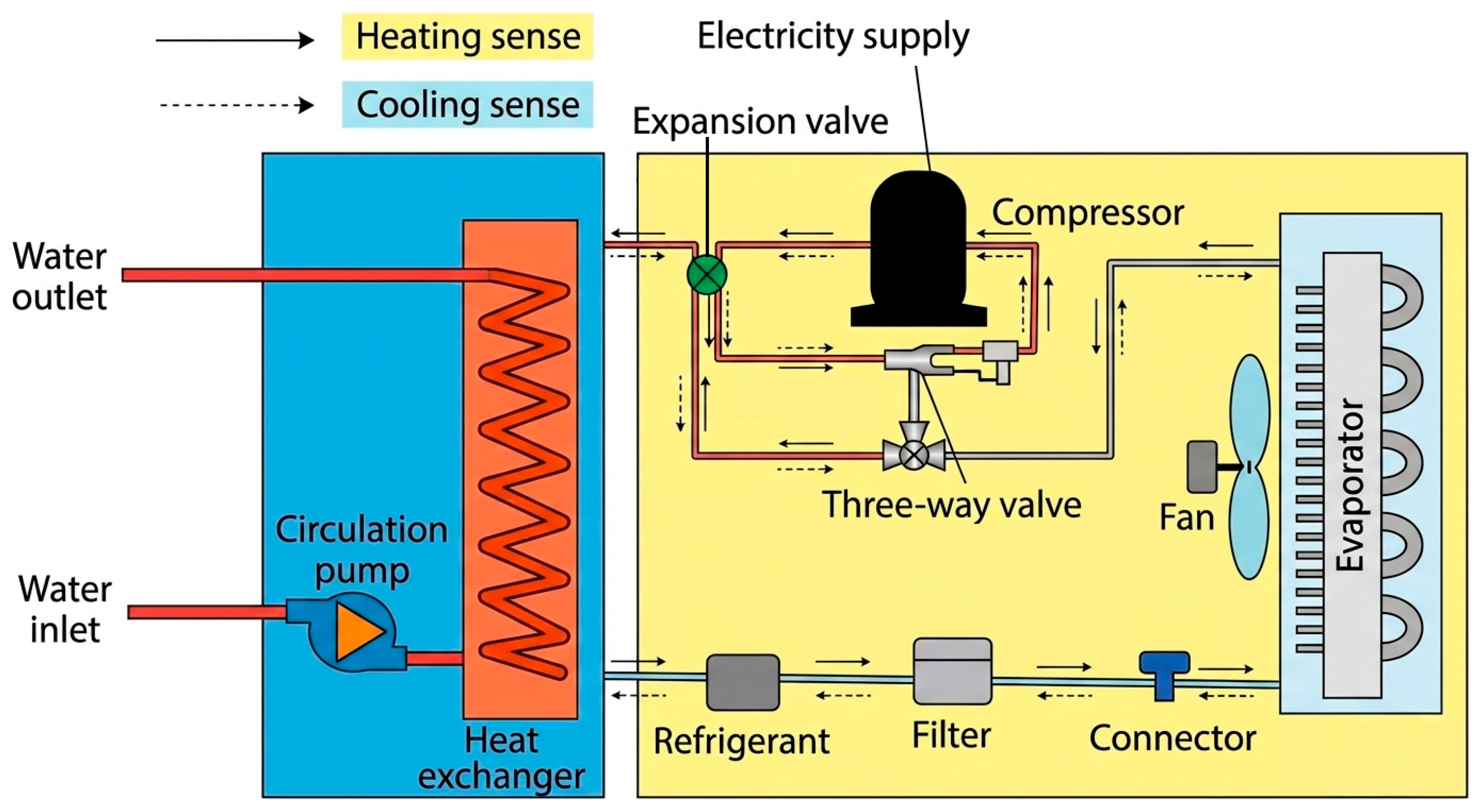
ASHPs can be classified by heat source-to-heat carrier as air-to-air HPs and air-to-water HPs. The operation of an ASHP’s reversed vapour-compression cycle consists of four primary parts: evaporator, compressor, condenser, and expansion valve (Figure 2). In the evaporator, the refrigerant absorbs heat from the environment and evaporates. The compressor then increases the refrigerant’s pressure and temperature. In the condenser, heat is released to the heating system, and the refrigerant condenses. Finally, the expansion valve reduces the pressure, and the cycle repeats.
The reversible ASHP can both heat and cool the building, thereby altering the direction of the thermal path.

2.2.2. Energy and Environmental Performances

The COP and COPsys can be used to describe the ASHP system’s energy efficiency when it is in heating mode [31]:
COP = E t E HP
COP s y s = E t E e l
in which:
E e l = E HP + E p + E a u x
where COPsys is the overall system COP (HP unit, water-circulating pumps, and additional equipment); Et is the produced thermal energy; EHP is the electrical energy utilised by the compressor; 3.412 is the conversion factor from watts to Btu/h; Eel is the electrical energy utilised by the system; Ep is the energy used by the circulating pump; and Eaux is the electricity utilised by auxiliary equipment.
SCOP is a weighted-average figure that represents an HP’s overall efficiency for the whole heating season.
Indirect CO2 emissions linked to the production of electrical energy are the largest environmental impact of utilising electric HPs. To determine the indirect CO2 emissions ( M CO 2 ), in kg, during HP operation, the following equation can be used:
M CO 2 = g e l E e l
where gel is the CO2 content of electricity, which is estimated to be 0.400 kg CO2/kWh in Romania [32].

2.2.3. Integration into District Heating Systems

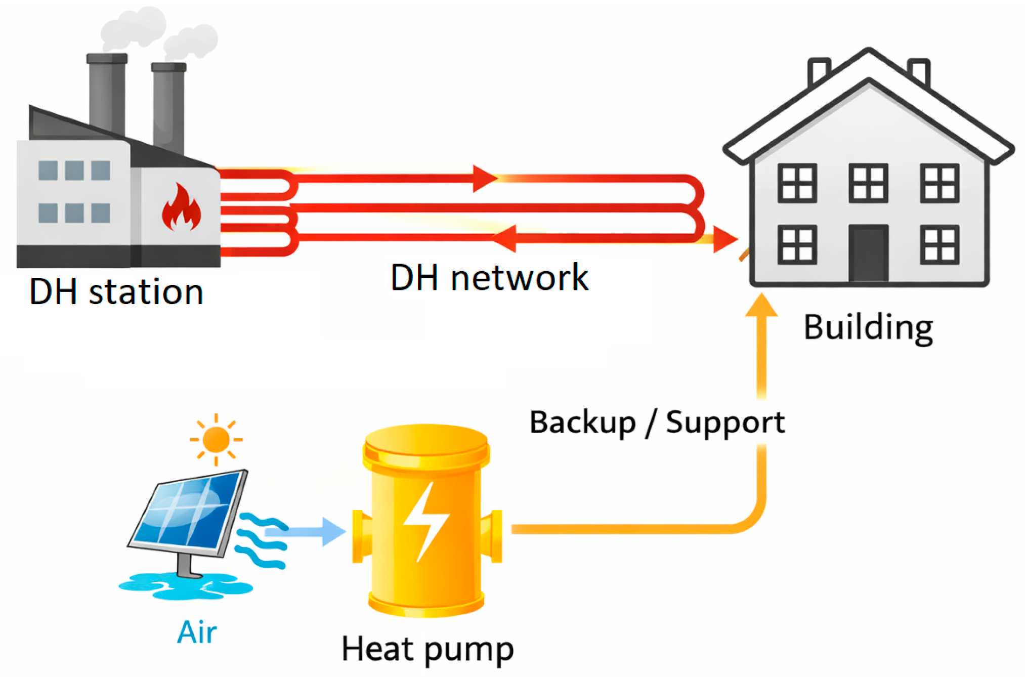
The integration of HPs into DH systems (Figure 3) represents a key pathway for decarbonising the heating sector. HPs can be implemented at both the centralised level within district heating stations and the decentralised level in buildings connected to the network.
A critical aspect of integration is identifying available heat sources, such as wastewater, geothermal sources, and industrial waste heat [33]. The use of these sources enhances system efficiency and reduces carbon emissions.

3. Methodology

The methodology was organised into three main components covering case study description, hybrid system modelling, and simulation scenarios for improved clarity.

3.1. Case Study and Hybrid System Configuration

The case study is carried out on an existing building connected to a central heating system, used to ensure the heating and DHW needs are met. It is an office building (Figure 4) with a heated area of 8600 m2 (B + GF + 7F), located in Timisoara, Romania, and supplied with thermal energy from the DH system, using natural gas as the heat source.
The building is a concrete-framed structure. The exterior walls are 5 cm thick glass curtain type, and the interior walls are 15 cm thick plasterboard. The glazed area is 5280 m2. The indoor and outdoor air design temperatures are +20 and −15 °C, respectively, in heating mode. The building’s heating demand is 1224 MWh, and the DHW heat demand at 45 °C is 4458 kWh. The specific annual energy requirement for heating is 142.3 kWh/m2/a.
The heating of the office building is achieved using a DH substation located in a dedicated space in the building’s basement, which produces 80/60 °C hot water as a heat carrier and features a fully equipped, automated thermal module, circulating pumps, and an expansion installation. A two-pipe system composed of drawn black steel pipe, thermally insulated with a 50 mm-thick mineral wool mattress coated in aluminium foil, is used to distribute the heat carrier.
The office building spaces are heated by an air handling unit (AHU) with unenclosed fan coil units (FCUs) mounted in the false ceiling.
In practice, the operation of the DH system is characterised by significant variations in supply temperature and interruptions, making it difficult to maintain an adequate level of indoor thermal comfort. Thus, over the past three years, the DH system has experienced numerous problems, including extended periods of low-temperature supply and disruptions to the heat carrier. The building was supposed to be supplied with a heat carrier at a constant 90 °C, but during the cold seasons of 2021 and 2022, there were several days when it was supplied at 60–70 °C.
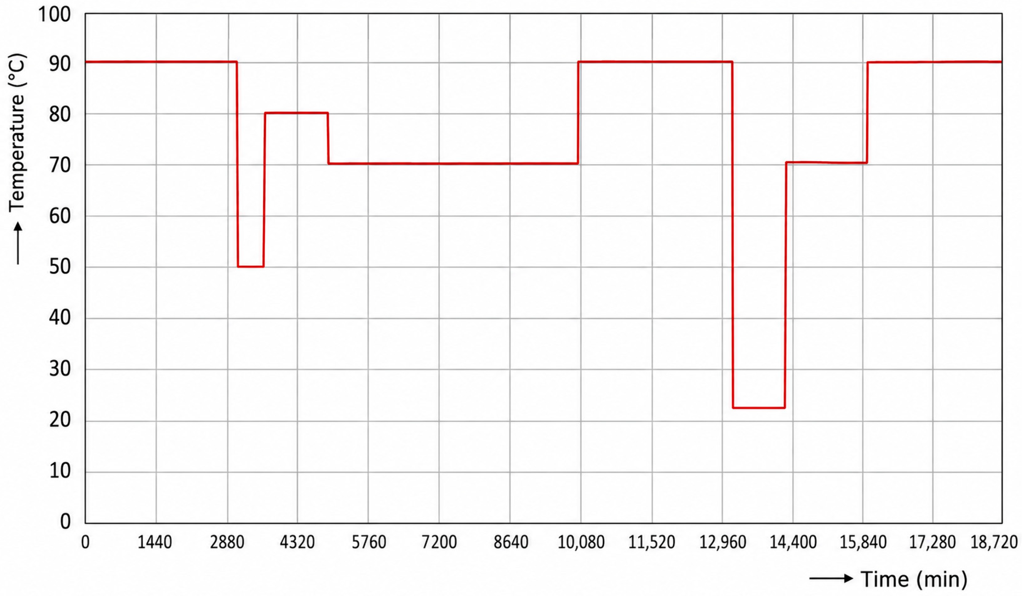
Figure 5 shows the variations in the supply heat carrier temperature recorded by the building’s Building Management System (BMS) over 14 days from February 2022. The heat carrier temperature dropped below 70 °C for approximately 4 days. There were also interruptions in the heat carrier, during which the temperature dropped to around 25 °C for 10–12 h. At these temperatures, the entire heating and DHW supply could not be provided. Following these failures and interruptions in the heat carrier, we propose supplementing the existing heating system with an air-to-water HP.
Operational data used in this study were acquired through the BMS and included supply and return temperatures, indoor temperatures and thermal load indicators, recorded at hourly resolution. These data were used both to define simulation boundary conditions and to support model calibration. The selected representative period illustrated in Figure 6 corresponds to a documented interval of significant DH instability. It is used as a reference period to characterise supply interruptions and support the definition of hybrid system operation. Monitored variables and data used for model input/calibration are presented in Table 3.
Additional analysis of monitored DH operation indicated repeated supply temperature drops below nominal levels and several interruption events lasting 10–12 h each. The 14 days shown in Figure 5 were selected as a representative interval encompassing the most significant instability events and used to support the definition of hybrid system operating conditions and simulation boundary assumptions. Statistical characterisation of DH supply instability is presented in Table 4.
To compensate for the limitations of the DH system, an air-to-water HP unit, type KAPPA V Energy 51.2, was integrated at the building level, creating a hybrid system.
HP uses R134A as its refrigerant and has a scroll electro-compressor. An electronic controller ensures the HP operates by turning the compressor on or off in response to the system’s water return temperature. Table 5 summarises the primary characteristics of the air-to-water HP unit.
In this configuration, the DH system remains the primary source of thermal energy. At the same time, the HP operates as an auxiliary system, supplementing heating capacity and ensuring continuity of supply.
The HP is connected in parallel with the existing system, with minimal modifications to the building infrastructure, and operates in accordance with the DH system’s operating conditions. This approach allows maintaining the existing system architecture and assessing the feasibility of integrating HPs into buildings already connected to DH networks.

3.2. Control Strategy and Simulation Scenarios

The hybrid system uses a technical (bivalent parallel) control strategy, in which the HP and DH systems operate simultaneously when needed. The HP activation is determined by the network-supplied temperature and the building’s indoor temperature. No economic optimisation based on energy prices was considered in this study.
Thus, the HP is activated when the supply temperature drops below a predefined threshold, typically 50–55 °C, or when the indoor temperature cannot be maintained at the desired level. In the event of a DH interruption, the HP partially meets the heating demand, ensuring system continuity. This strategy enables dynamic adaptation to operating conditions and optimisation of energy consumption.
Within Polysun [34], the system is solved through an hourly thermal balance in which the combined contributions of DH and the HP meet building demand. HP activation follows a threshold-based control linked to supply and indoor temperatures.
To evaluate system performance, two operating scenarios were defined to reflect different operating conditions of the DH system. In the first scenario, the building is supplied exclusively by the DH system, without the HP, representing the conventional configuration and serving as a reference for evaluating the existing system’s performance. In the second scenario, the system operates in hybrid mode, with the HP supporting the DH system when operating conditions are insufficient to meet the heating demand. This scenario reflects the integration of renewable-based technologies into existing systems.
These scenarios enable a comparative analysis of system performance and energy savings and highlight HP’s role in improving reliability and energy efficiency.
Although the study is primarily based on two comparative operating configurations, additional sensitivity analyses were conducted to evaluate the effects of variations in HP activation threshold and DH supply conditions. This allows assessment of system behaviour across different operating regimes and complements the baseline-scenario comparison.

3.3. Simulation Model and Boundary Conditions

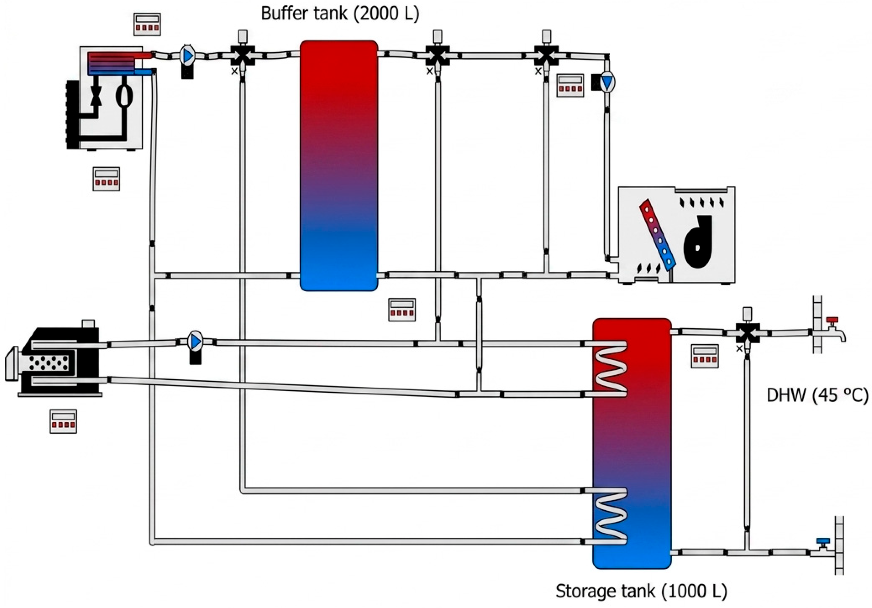
The analysed system consists of two heating configurations modelled using the Polysun simulation environment: (1) a conventional DH system and (2) a hybrid system integrating an air-to-water HP (Figure 6). The study is conducted to evaluate system performance, energy consumption, and operational behaviour under varying climatic conditions.
The model includes representations of the DH source, the HP, the heat distribution system, and the building, along with their interactions.
The DH source is modelled as a variable-temperature input based on real data or representative profiles. In the simulations, the DH source was modelled using measured operating conditions recorded by the BMS, including supply temperature variations between approximately 60 °C and 90 °C, as well as interruption events lasting 10–12 h. These operating disturbances were introduced as boundary conditions to reproduce the actual instability of the DH system. At the same time, the HP is defined by its performance characteristics, which depend on outdoor temperature and operating conditions. The building model is used to determine heating demand and to evaluate indoor temperature, which are correlated with external climatic conditions.
The simulations were performed with an hourly time step, allowing the system’s dynamic behaviour to be accurately captured.
The conventional configuration relies exclusively on DH, modelled as a thermal source supplying the entire building’s heating demand. Based on the simulation results, the annual thermal energy consumption of the conventional system is approximately 1085 MWh, representing the reference scenario for comparison.
The hybrid configuration combines DH with an air-to-water HP to form a dual-source heating system. In this configuration, the total annual energy consumption is decreased to approximately 821 MWh, with about 690 MWh from DH and 131 MWh from electricity used by the HP.
At the core of the hybrid system lies a buffer tank (BT) with a typical volume of approximately 2000 L, which functions as a hydraulic separator and energy buffer between heat generation and consumption. This component enables the decoupling of heat production and demand, improving system flexibility and operational stability.
The HP subsystem is configured as an air-to-water unit with a nominal thermal capacity of 320–380 kW, depending on outdoor temperature conditions. Its performance varies significantly with ambient temperature, with COP values ranging from approximately 1.8 at −5 °C to 3.0 at 15 °C and a SCOP of about 3.6. The HP operates preferentially during periods with moderate outdoor temperatures, contributing significantly to the heating demand and reducing reliance on DH.
The design peak heating load of the building used for HP sizing is approximately 420 kW. Based on this load, an air-to-water HP with a nominal heating capacity of 530.5 kW and rated electrical power of approximately 142 kW (Air 7 °C/Water 40 °C) was selected, ensuring full coverage of the required heating demand with operational reserve.
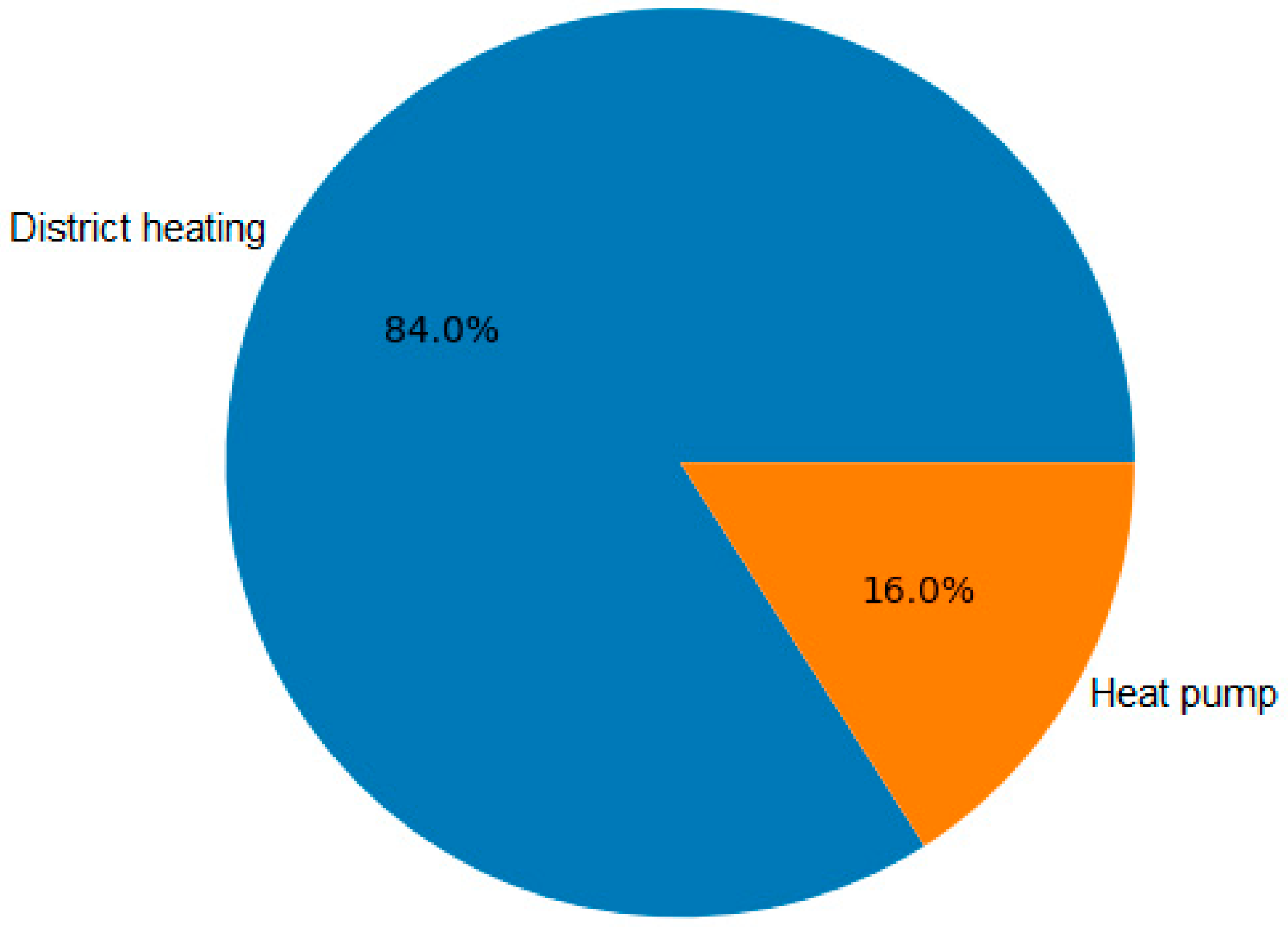
The DH system acts as a backup and peak-load source, ensuring full coverage of the building’s heating demand when the HP capacity is insufficient. In the hybrid configuration, it remains the dominant energy source, accounting for approximately 84% of total energy consumption, while the HP contributes around 16%.
Thermal energy is distributed throughout the building via FCUs and AHUs, operating at typical supply and return temperatures of approximately 60 °C and 50 °C, respectively. DHW is produced using a dedicated storage tank with a volume of approximately 1000 L, connected to the primary heating loop.
Climatic input data for the simulation were obtained from the Meteonorm database [35] for the Timisoara location (21.25° E, 45.75° N). This ensures a realistic representation of annual outdoor temperature variations and enables an accurate assessment of system performance over a typical meteorological year.

4. Results and Discussion

4.1. Behaviour of the District Heating System

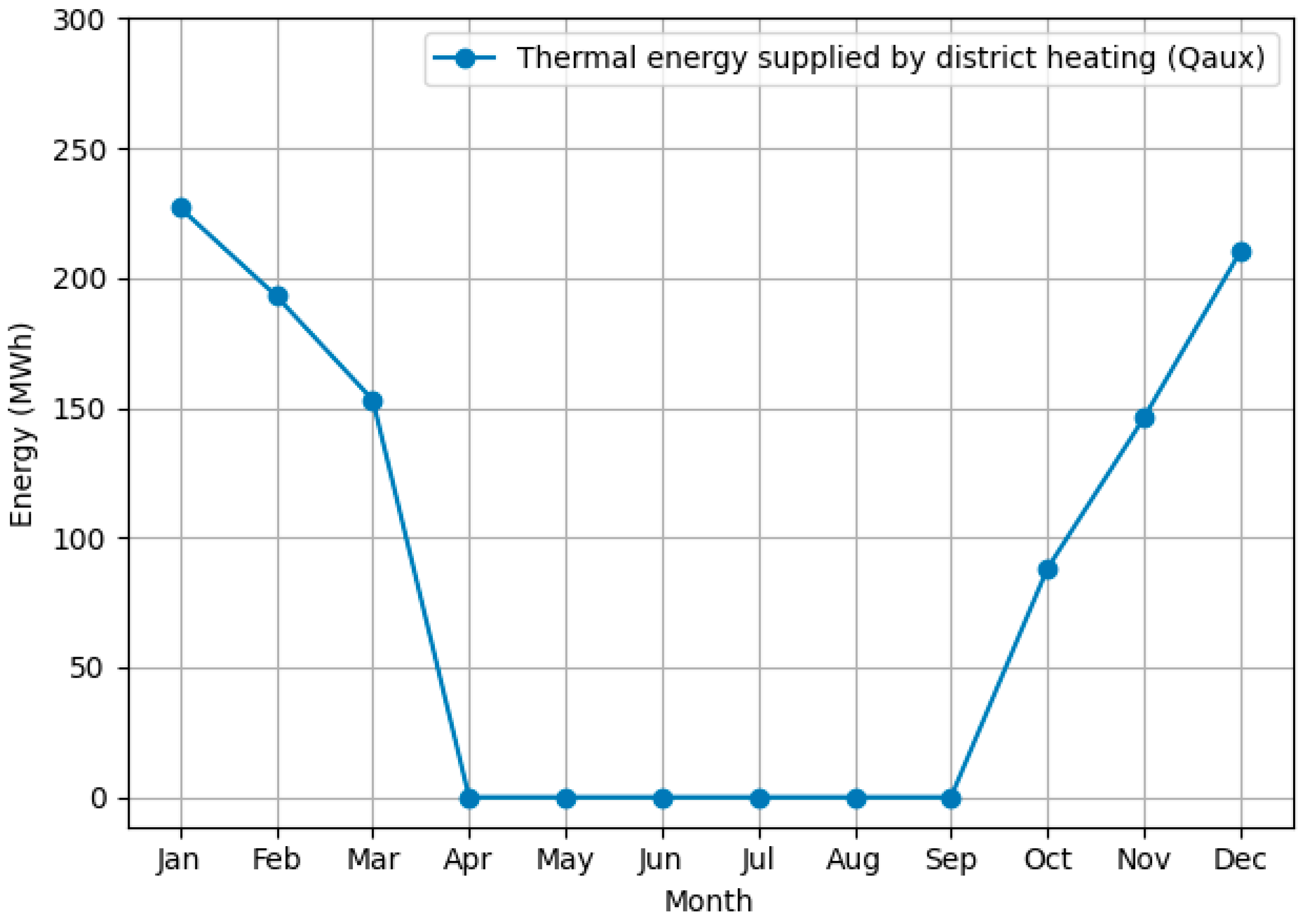
Figure 7 illustrates the monthly thermal energy supplied by the DH system in the conventional scenario. The results show a strong seasonal dependence, with peak energy delivery during the winter months (January, February, and December), corresponding to the highest heating demand.
During the transitional months (spring and autumn), the supplied energy decreases significantly, whereas, in the summer period, it becomes negligible, reflecting the absence of space-heating demand.
The annual energy balance confirms that the total supplied energy slightly exceeds the useful energy demand, indicating that the system can fully cover the building load without an energy deficit.

4.2. Heat Pump Operation in Hybrid System

Figure 8 illustrates the relationship between the HP operation and the outdoor temperature. The green bars represent the monthly average outdoor temperature, while the blue line indicates the thermal energy provided by the HP.
The HP operates more intensively during periods with moderate outdoor temperatures, when its efficiency is higher. As outdoor temperature decreases, the HP’s contribution decreases, confirming its temperature-dependent performance.
This behaviour highlights the HP’s role as a complementary source within the hybrid system, operating preferentially under favourable climatic conditions.
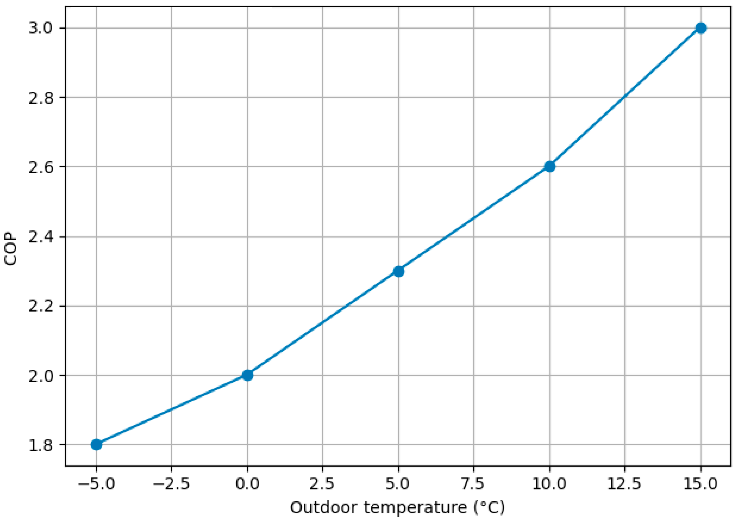
Figure 9 illustrates the variation in the HP’COP as a function of the outdoor temperature. The results show a clear increasing trend, with COP values rising from approximately 1.8 at low outdoor temperatures (−5 °C) to about 3.0 at higher temperatures (15 °C).
The temperatures of −5 °C and 15 °C were selected as representative boundary operating conditions corresponding to peak winter load and moderate seasonal conditions, respectively. Table 6 summarises COP variation under representative operating conditions.
This behaviour reflects the thermodynamic characteristics of air-to-water HPs, which operate more efficiently under milder climatic conditions. As outdoor temperatures increase, the temperature lift required by the HP decreases, improving performance.
These results are consistent with the operational behaviour observed in the hybrid system, where the HP contributes more significantly during transitional periods.
The seasonal COP (SCOP) of the HP reaches approximately 3.6. This value represents the average seasonal performance obtained from annual dynamic simulation. It should be distinguished from the instantaneous COP values shown in Figure 9, which correspond only to selected representative operating points between −5 °C and 15 °C.
The higher SCOP value is explained by weighted seasonal operation, including part-load conditions and additional operating periods outside the analysed temperature points, where the HP may operate at higher efficiency. Therefore, SCOP should not be directly compared with the maximum point COP, since they represent different performance indicators.

4.3. Comparative Analysis of Scenarios

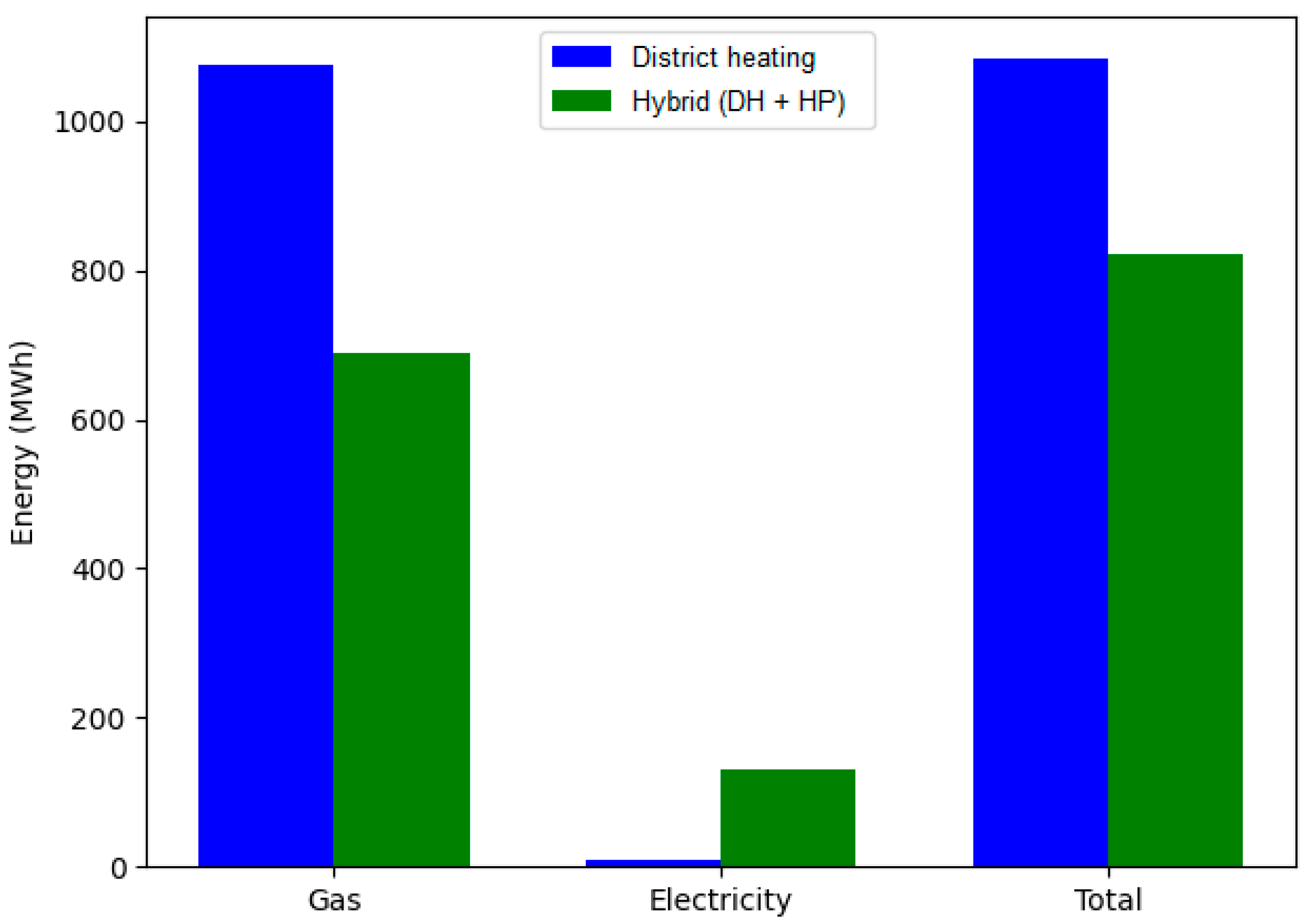
Figure 10 presents the comparative energy consumption between the conventional district heating system and the hybrid configuration. The blue bars represent the conventional system, while the green bars correspond to the hybrid system.
It is clear that the hybrid system significantly reduces natural gas consumption while increasing electricity use, driven by the heat pump’s operation. Despite this increase, the total energy consumption is considerably lower in the hybrid system. Overall, the hybrid configuration reduces total energy consumption by approximately 24% and natural gas usage by 36%, demonstrating improved system efficiency and a reduced environmental impact compared to the conventional DH system.

4.4. Impact on Energy Consumption (Hybrid System)

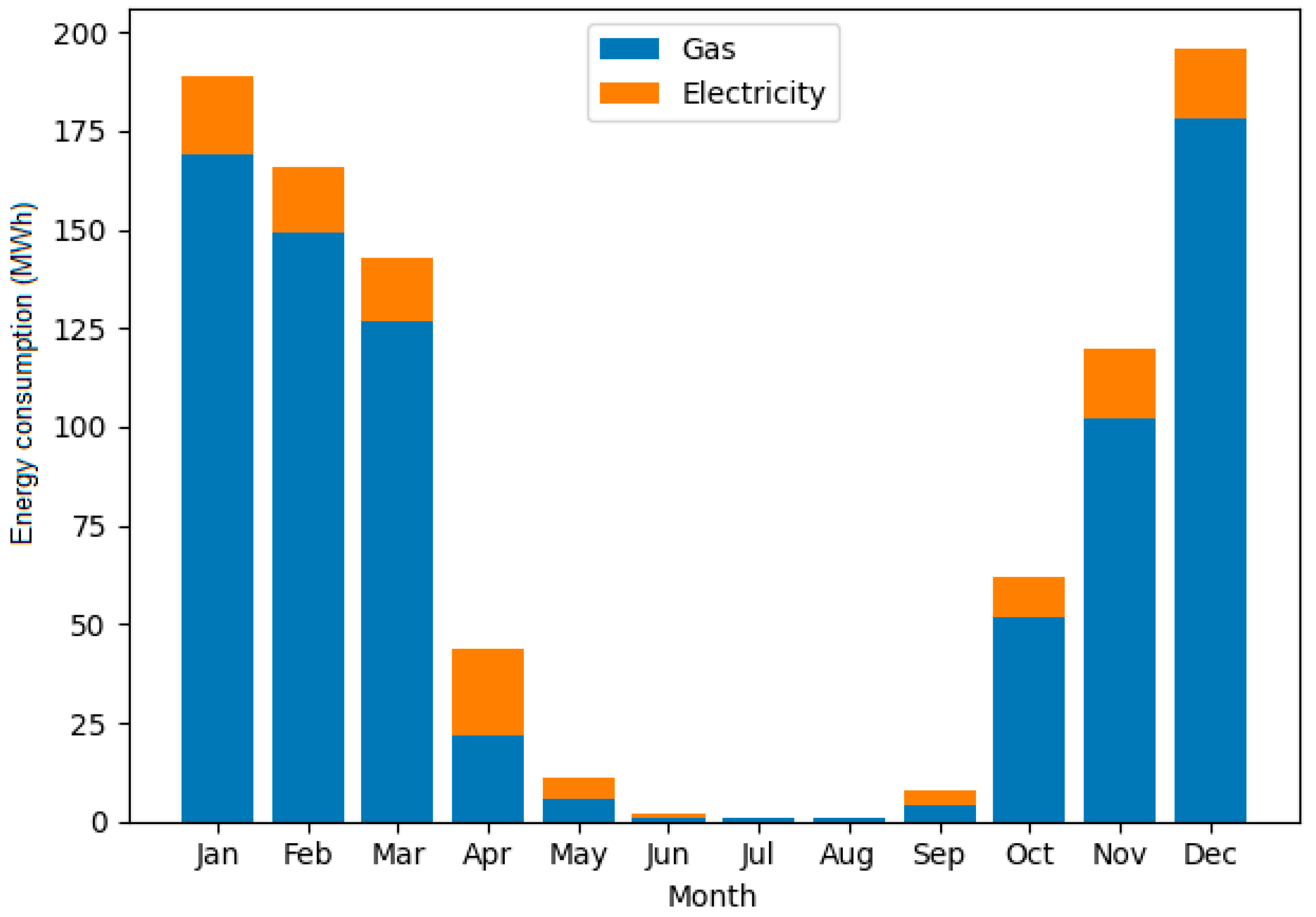
Figure 11 illustrates the hybrid system’s monthly energy consumption, highlighting the contributions of natural gas and electricity.
The results show that natural gas remains the dominant energy source during the winter months, when heating demand is highest. In contrast, electricity consumption becomes more relevant during transitional periods, reflecting increased HP operation under favourable outdoor conditions.
This distribution demonstrates the hybrid system’s ability to reduce reliance on fossil fuels by integrating electricity, leading to a more balanced and efficient energy mix.

4.5. CO2 Emissions

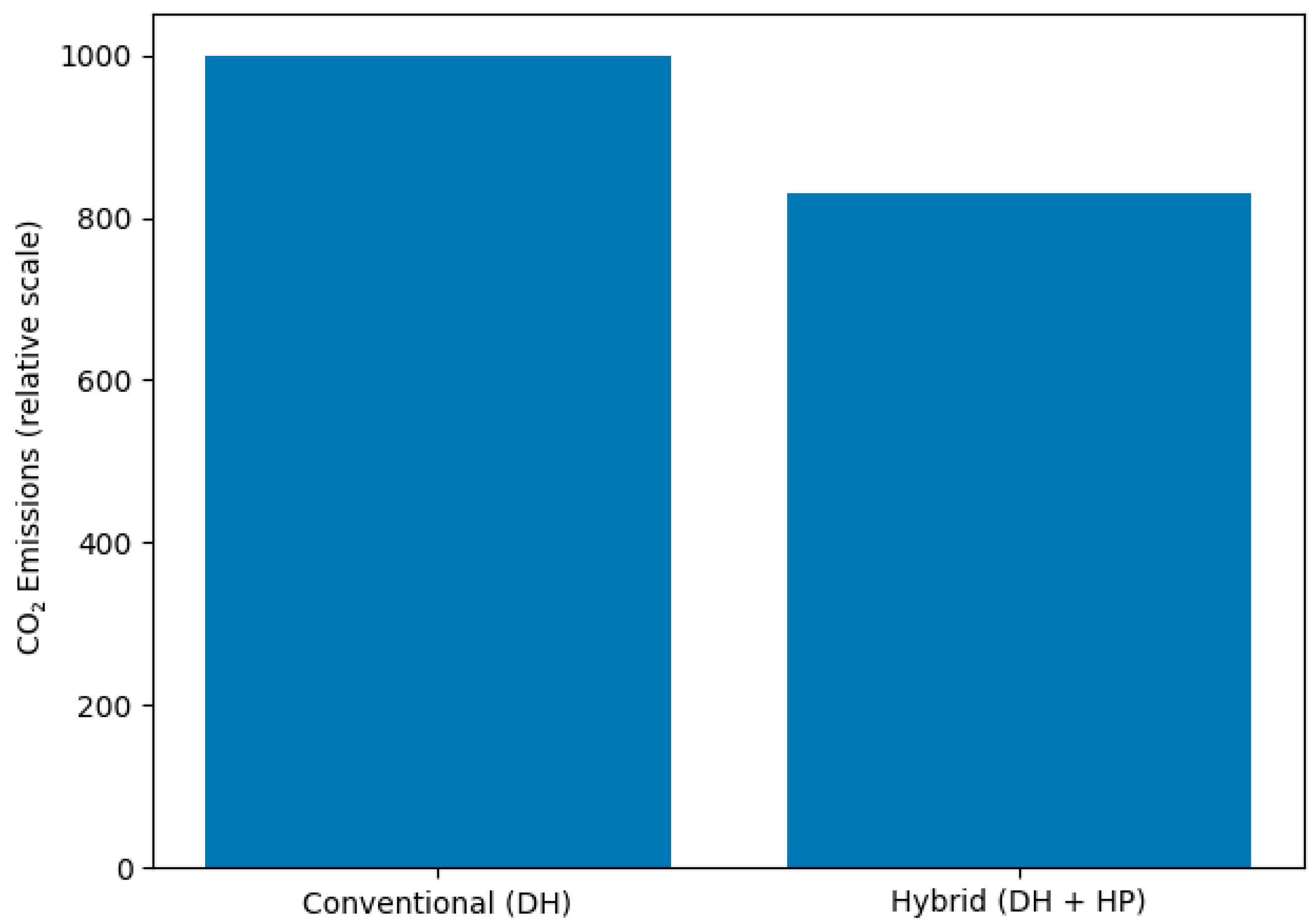
Figure 12 compares CO2 emissions between the conventional DH system and the hybrid configuration.
CO2 emissions were calculated separately for natural gas and electricity consumption using the corresponding emission factors presented in Table 2. For the conventional scenario, emissions were determined based on natural gas consumption according to:
M CO 2 = g g a s E g a s
where Egas is the annual natural gas consumption, and ggas is the corresponding emission factor.
For the hybrid scenario, total emissions were calculated as the sum of emissions associated with natural gas and electricity use:
M CO 2 = g g a s E g a s + g e l E e l
where Eel represents the electricity consumption of the HP, and gel is the electricity emission factor.
The comparison was performed consistently for both scenarios using the same system boundaries.
Using the adopted factors (ggas = 0.202 kg/kWh and gel = 0.400 kg/kWh), emissions decrease from approximately 220 t CO2/year in the conventional case to 191 t CO2/year in the hybrid configuration.
The results clearly indicate a significant reduction in emissions when the HP is integrated into the system. This reduction is primarily due to decreased natural gas consumption, partially replaced by electricity used to operate the HP. Despite increased electricity consumption, the overall carbon footprint is lower due to HP’s higher efficiency and the lower electricity emission factor.
These findings confirm that hybrid systems represent an effective solution for reducing GHG emissions while maintaining reliable system performance.

4.6. Contribution of Energy Source

Figure 13 illustrates the contributions of the main energy sources in the hybrid system using a pie chart. DH accounts for the dominant share of total energy consumption, approximately 84%, while HP accounts for about 16%.
This result indicates that DH remains the primary energy source; however, the integration of the air-to-water HP provides a meaningful share of the total energy demand. Despite its lower contribution, the HP plays a crucial role in improving system efficiency and reducing reliance on fossil fuels.
Overall, the results highlight a transition toward a more diversified and sustainable energy mix.

4.7. Load Coverage

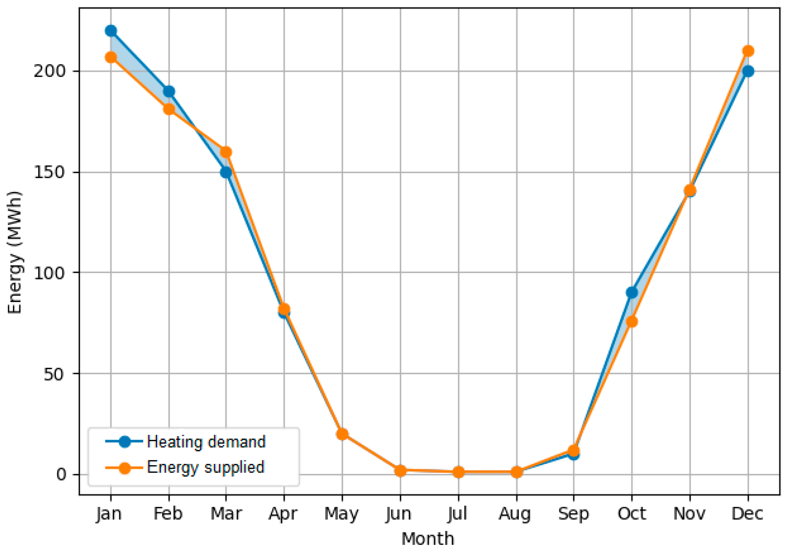
Figure 14 compares the heating demand with the energy supplied by the hybrid system. The shaded area between the curves highlights the difference between demand and supply.
The two curves closely overlap throughout the year, indicating that the system effectively meets the heating demand. The shaded regions are minimal, indicating only minor deviations, attributed to system control dynamics and operational variations.
Overall, the results confirm that the hybrid system ensures reliable load coverage with negligible deficit, demonstrating proper sizing and efficient operation.

4.8. Energy and Environmental Performance Analysis

The simulation results demonstrate the operation of both the conventional DH system and the hybrid configuration under realistic climatic conditions, allowing a direct comparison of their energy and environmental performance.
In the conventional scenario (DH only), the total useful thermal energy delivered to the building (Quse) was approximately 1017 MWh. In comparison, the total thermal energy supplied by the system (Qaux) reached about 1019 MWh.
This result indicates that the system can fully meet the building’s thermal demand, with a slight surplus of supplied energy. The difference between supplied and utilised energy is due to distribution losses and the system’s control dynamics.
The total system energy consumption (Etot) was approximately 1085 MWh, with natural gas representing the dominant energy source (Egas ≈ 1076 MWh), while electricity consumption remains negligible (Eel ≈ 9 MWh).
The system energy performance ratio calculated with Equation (1) remains below unity (ηsys ≈ 0.9), which is typical for conventional fossil-fuel-based heating systems.
In contrast, the hybrid scenario (DH + HP) shows a significant improvement in overall performance. The Quse increased to approximately 1090 MWh, closely matching the system output, confirming proper system sizing and reliable operation without an energy deficit. The Etot decreased to about 821 MWh, consisting of Egas ≈ 690 MWh and Eel ≈ 131 MWh.
The HP contributes approximately 440 MWh (57%) of thermal energy, with a SCOP of about 3.6, confirming its high efficiency under favourable outdoor conditions.
As a result, the system energy performance ratio exceeds unity (ηsys ≈ 1.3) due to the integration of renewable energy from the ambient environment. In this study, ηsys represents a system-level energy performance indicator rather than a conventional thermal conversion efficiency. For the conventional DH case, ηsys remains below unity due to distribution losses and conversion inefficiencies. In the hybrid case, ηsys may exceed unity because the HP utilises ambient renewable energy in addition to electrical input, thereby increasing useful delivered thermal energy beyond directly supplied purchased energy. This interpretation is consistent with the thermodynamic behaviour of HP-based systems and should not be confused with the COP or SCOP indicators.
Table 7 summarises the main energy performance indicators of the analysed systems, highlighting reductions in total energy consumption, shifts in the energy mix, and the HP’s contribution in the hybrid configuration.
Table 8 presents the comparison of CO2 emissions between the conventional and hybrid systems. The results show a significant reduction in emissions associated with natural gas consumption, partially offset by an increase in electricity-related emissions from HP operation. Overall, the hybrid system achieves a net reduction in total CO2 emissions.
From an environmental perspective, the hybrid system achieves a significant reduction in CO2 emissions. The results indicate a total emission reduction of approximately 29,000 kg/year, mainly due to the partial replacement of natural gas with electricity-driven HP operation.
Although electricity consumption increases, its lower carbon intensity reduces overall emissions.
The comparisons performed highlight the clear advantages of the hybrid system. While the conventional DH system relies almost entirely on fossil fuels, the hybrid configuration ensures full load coverage, reduces primary energy consumption, and significantly improves operational flexibility and environmental performance. These findings confirm the potential of hybrid systems as an effective transitional solution toward low-carbon heating.
A sensitivity assessment was performed considering moderate variations in key input parameters, including HP control threshold and performance assumptions. The results indicate that while absolute energy savings vary within a limited range, the hybrid configuration’s comparative advantage remains consistent. In addition, climatic variability is inherently captured through the hourly simulation over a typical meteorological year, which captures seasonal fluctuations that affect system performance.
The energy savings and HP performance achieved are also consistent with trends reported in previous studies on hybrid DH systems, which have observed reductions in primary energy use and improved operational flexibility. This comparison supports the plausibility and broader relevance of the results.
The sensitivity analysis of key input parameters is presented in Table 9.
Energy savings remained in the range of approximately 21–26%, confirming the robustness of the observed 24% baseline result.


5. Study Limitations

Although the proposed hybrid solution demonstrates significant energy and environmental benefits, several limitations of the study should be acknowledged. The present analysis focused primarily on technical and environmental performance, while economic aspects such as initial investment, operational costs, maintenance requirements and equipment lifetime were not explicitly evaluated. These factors may significantly influence the practical feasibility and large-scale implementation of such systems. Therefore, future work should include techno-economic analysis and life-cycle cost assessment to provide a more comprehensive evaluation of the proposed hybrid solution.
Additionally, the analysis does not include a detailed assessment of the existing electrical infrastructure. The proposed configuration assumes sufficient electrical capacity for HP integration, while in practical applications, additional assessment and potential upgrades may be required.
The results are specific to the climatic conditions considered in this study. In colder climates, the HP’s performance may decrease, leading to higher electricity consumption and a potential reliance on auxiliary electric heating. Therefore, the overall system performance may be reduced under such conditions.

6. Conclusions

The present study evaluated the integration of an air-to-water HP into an existing office building supplied by a DH system using dynamic simulation with Polysun 4 software.
The results demonstrate that hybridisation significantly improves system performance, leading to approximately a 24% reduction in total energy consumption and 36% in natural gas use, highlighting the effectiveness of combining conventional and renewable technologies.
Although integrating the HP increases electricity consumption, this is offset by the system’s higher efficiency, as reflected in the SCOP of approximately 3.6. This SCOP further confirms the high annual efficiency of the proposed hybrid system under variable operating conditions.
The analysis confirms that the hybrid system can fully meet the heating demand with a negligible deficit, ensuring reliable operation under varying climatic conditions and validating the adopted control strategy.
From an environmental perspective, the hybrid configuration leads to a reduction of approximately 29 t CO2 per year, demonstrating its potential contribution to decarbonisation objectives and sustainable building operation.
The results also highlight the importance of distinguishing between energy input share and thermal contribution, as the HP accounts for a relatively small share of electricity consumption while delivering a significantly higher share of useful thermal energy.
Furthermore, the study demonstrates that integrating HPs can be achieved without major modifications to existing building infrastructure, making it a practical and scalable solution for retrofit applications in urban environments.
Finally, the proposed hybrid approach enhances system flexibility and resilience, particularly when the DH system operates at reduced capacity or under variable conditions, ensuring the continuity of thermal supply.

Author Contributions

Conceptualization, A.D. and I.S.; methodology, I.S.; software, A.D.; validation, A.D. and I.S.; formal analysis, A.D.; investigation, A.D. and I.S.; resources, A.D.; data curation, A.D.; writing—original draft preparation, I.S.; writing—review and editing, I.S.; visualization, A.D. and I.S.; supervision, I.S.; project administration, I.S. All authors have read and agreed to the published version of the manuscript.
Funding

This research received no external funding.

Institutional Review Board Statement

Not applicable.

Informed Consent Statement

Not applicable.

Data Availability Statement

The original contributions presented in this study are included in the article. Further inquiries can be directed to the corresponding author.

Conflicts of Interest

The authors declare no conflicts of interest.

Abbreviations

The following abbreviations are used in this manuscript:
AHUAir handling unit
ASHPAir-source heat pump
BMSBuilding Management System
BTBuffer tank
COPCoefficient of performance
CHPCombined Heat and Power
DHDistrict heating
DHCDistric heating and cooling
DHWDomestic hot water
EUEuropean Union
FCUFan coil unit
GHGGreenhouse gas
HPHeat pump
IEAInternational Energy Agency
RESRenewable energy sources
TESThermal energy storage

References

  1. UNEP. Global Status Report for Buildings and Construction: Towards a Zero-Emission, Efficient and Resilient Buildings and Construction Sector; United Nations Environment Programme: Nairobi, Kenya, 2021. [Google Scholar]
  2. EC. Energy Efficiency in Buildings—Factsheet; European Commission: Brussels, Belgium, 2024. [Google Scholar]
  3. IEA. World Energy Outlook 2020; International Energy Agency: Paris, France, 2020. [Google Scholar]
  4. Knobloch, F.; Pollitt, H.; Chewpreecha, U.; Daioglou, V.; Mercure, J.F. Simulating the deep decarbonization of residential heating for limiting global warming to 1.5 °C. Energy Effic. 2019, 12, 521–550. [Google Scholar] [CrossRef] [Scilit]
  5. Sadeghi, H.; Singh, R.M. Driven precast concrete geothermal energy piles: Current state of knowledge. Build. Environ. 2023, 228, 109790. [Google Scholar] [CrossRef] [Scilit]
  6. IEA. Heating—Analysis; International Energy Agency: Paris, France, 2022. [Google Scholar]
  7. Sarbu, I.; Dorca, A.; Mirza, M. Exhaustive overview of advances in integrating renewable energy sources into district heating systems. Sustain. Cities Soc. 2024, 116, 105897. [Google Scholar] [CrossRef] [Scilit]
  8. Lund, H.; Werner, S.; Wiltshire, R.; Svendsen, S.; Thorsen, J.E.; Hvelplund, F.; Mathiesen, B.V. 4th generation district heating (4GDH): Integrating smart thermal grids into future sustainable energy systems. Energy 2014, 68, 1–11. [Google Scholar] [CrossRef] [Scilit]
  9. Kitsopoulou, A.; Zacharis, A.; Ziozas, N.; Bellos, E.; Iliadis, P.; Lampropoulos, I.; Chatzigeorgiou, E.; Angelakoglou, K.; Nikolopoulos, N. Dynamic energy analysis of different heat pump heating systems exploiting renewable energy sources. Sustainability 2023, 15, 11054. [Google Scholar] [CrossRef] [Scilit]
  10. Arpagaus, C.; Bless, F.; Uhlmann, M.; Schiffmann, J.; Bertsch, S.S. High temperature heat pumps: Market overview, state of the art, research status, refrigerants, and application potentials. Energy 2018, 152, 985–1010. [Google Scholar] [CrossRef] [Scilit]
  11. EHPA. Heat Pump Record: 3 Million Units Sold in 2022, Contributing to REPowerEU Targets; European Heat Pump Association: Brussels, Belgium, 2023. [Google Scholar]
  12. Dermentzis, G.; Ochs, F.; Thuer, A.; Streicher, W. Supporting decision-making for heating and distribution systems in a new residential district-An Austrian case study. Energy 2021, 224, 120141. [Google Scholar] [CrossRef] [Scilit]
  13. Volodina, V.; Wheatcroft, E.; Wynn, H. Comparing district heating options under uncertainty using stochastic ordering. Sustain. Energy Grids Netw. 2022, 30, 100634. [Google Scholar] [CrossRef] [Scilit]
  14. David, A.; Mathiesen, B.V.; Averfalk, H.; Werner, S.; Lund, H. Heat roadmap Europe: Large-scale electric heat pumps in district heating systems. Energies 2017, 10, 578. [Google Scholar] [CrossRef] [Scilit]
  15. Ochs, F.; Magni, M.; Dermentzis, G. Integration of heat pumps in buildings and district heating systems—Evaluation on a Building and Energy System Level. Energies 2022, 15, 3889. [Google Scholar] [CrossRef] [Scilit]
  16. Xue, T.; Jokisalo, J.; Kosonen, R. Cost-effective control of hybrid ground source heat pump system coupled with district heating. Buildings 2024, 14, 1724. [Google Scholar] [CrossRef] [Scilit]
  17. Jodeiri, A.M.; Goldsworthy, M.J.; Buffa, S.; Cozzini, M. Role of sustainable heat sources in transition towards fourth generation district heating–A review. Renew. Sustain. Energy Rev. 2022, 158, 112156. [Google Scholar] [CrossRef] [Scilit]
  18. Sarbu, I.; Dorca, A. Advances in District Heating Systems and Integrating Renewables: Fundamentals, Experiments, and Applications; Springer: Cham, Switzerland, 2026. [Google Scholar]
  19. Buffa, S.; Cozzini, M.; D’Antoni, M.; Baratieri, M.; Fedrizzi, R. 5th generation district heating and cooling systems: A review of existing cases in Europe. Renew. Sustain. Energy Rev. 2019, 104, 504–522. [Google Scholar] [CrossRef] [Scilit]
  20. Sorknæs, P.; Østergaard, P.A.; Thellufsen, J.; Lund, H.; Nielsen, S.; Djørup, S.; Sperling, K. The benefits of 4th generation district heating in a 100% renewable energy system. Energy 2020, 213, 119030. [Google Scholar] [CrossRef] [Scilit]
  21. Dang, L.M.; Nguyen, I.Q.; Nam, J.; Nguyen, T.N.; Lee, S.; Song, H.K.; Moon, H. Fifth generation district heating and cooling: A comprehensive survey. Energy Rep. 2024, 11, 1723–1741. [Google Scholar] [CrossRef] [Scilit]
  22. Menapace, A.; Boscheri, W.; Baratieri, M.; Righetti, M. An efficient numerical scheme for the thermo-hydraulic simulations of thermal grids. Int. J. Heat Mass Transf. 2020, 161, 120304. [Google Scholar] [CrossRef] [Scilit]
  23. IEA. District Heating; International Energy Agency: Paris, France, 2021. [Google Scholar]
  24. IEA. How Can District Heating Help Decarbonise the Heat Sector by 2024; International Energy Agency: Paris, France, 2019. [Google Scholar]
  25. Ürge-Vorsatz, D.; Cabeza, L.F.; Serrano, S.; Barreneche, C.; Petrichenko, K. Heating and cooling energy trends. Renew. Sustain. Energy Rev. 2015, 41, 85–98. [Google Scholar] [CrossRef] [Scilit]
  26. Pellegrini, M.; Bianchini, A. The Innovative concept of cold district heating networks: A literature review. Energies 2018, 11, 236. [Google Scholar] [CrossRef] [Scilit]
  27. Pans, M.A.; Claudio, G.; Eames, P.C. Theoretical cost and energy optimisation of a 4th generation net-zero district heating system with different thermal energy storage technologies. Sustain. Cities Soc. 2024, 100, 105064. [Google Scholar] [CrossRef] [Scilit]
  28. Sarbu, I.; Sebarchievici, C. Thermal energy storage. In Solar Heating and Cooling Systems: Fundamentals, Experiments and Applications; Elsevier: Oxford, UK, 2017; pp. 99–138. [Google Scholar]
  29. Laue, H.J.; Jakobs, R.M.; Thiemann, A. Energy efficiency and CO2 reduction in the building stock: The role of heat pumps. Rehva J. 2008, 45, 34–38. [Google Scholar]
  30. EC. Intelligent Energy Europe (IEE); European Commission: Brussels, Belgium, 2013. [Google Scholar]
  31. Sarbu, I.; Sebarchievici, C. Ground-Source Heat Pumps: Fundamentals, Experiments and Applications; Elsevier: Oxford, UK, 2016. [Google Scholar]
  32. Ministry of Regional Development, Public Administration and European Funds. MDRAPFE Order No. 2641 Regarding the Modification and Completion of the Technical Regulation “Methodology for Calculating the Energy Performance of Buildings”; Ministry of Regional Development, Public Administration and European Funds: Bucharest, Romania, 2017. (In Romanian) [Google Scholar]
  33. Lund, R.; Persson, U. Mapping of potential heat sources for heat pumps for district heating in Denmark. Energy 2016, 110, 129–138. [Google Scholar] [CrossRef] [Scilit]
  34. Polysun Software, version 4. User manual. Vela Solaris AG: Winttterthur, Switzerland, 2026.
  35. Meteonorm, version 8.0. Help. Meteonorm Software: Bern, Switzerland, 2020.
Figure 1. Scheme of a district heating system.
Sustainability 18 04965 g001
Figure 2. Operating scheme of a reversible air-to-water HP.
Sustainability 18 04965 g002
Figure 3. Integration of an HP into the DH system.
Sustainability 18 04965 g003
Figure 4. Photo of the reference office building.
Sustainability 18 04965 g004
Figure 5. Variation in the heat carrier supply temperature.
Sustainability 18 04965 g005
Figure 6. Hybrid system configuration for simulation with Polysun program.
Sustainability 18 04965 g006
Figure 7. Monthly thermal energy supplied by district heating.
Sustainability 18 04965 g007
Figure 8. Heat pump operation vs. outdoor temperature.
Sustainability 18 04965 g008
Figure 9. Variation in heat pump performance with outdoor temperature.
Sustainability 18 04965 g009
Figure 10. Comparative energy consumption between DH and DH+HP systems.
Sustainability 18 04965 g010
Figure 11. Impact on energy consumption.
Sustainability 18 04965 g011
Figure 12. CO2 emissions comparison.
Sustainability 18 04965 g012
Figure 13. Contribution of energy sources (hybrid system).
Sustainability 18 04965 g013
Figure 14. Comparison of the heating demand with the energy supplied throughout the year.
Sustainability 18 04965 g014
Table 1. Positioning of the present study versus the literature.
StudyEnergy AnalysisReal DH InstabilityResilience AnalysisReal Case
LiteratureLimitedNoMostly no
Present study
Table 2. CO2 intensity for different primary energy sources.
No.Fuel TypeCO2 Emission per kWh of Fuel (kg/kWh)CO2 Emission per kWh of Useful Heat (kg/kWh)
1Coal0.3400.49
2Oil0.2800.35
3Natural gas0.2020.24
4Electricity0.4000.19
Table 3. Monitored variables and data used for model input/calibration.
VariableSourceResolutionUse in Model
Supply temperatureBMS1 hBoundary condition
Return temperatureBMS1 hCalibration
Indoor temperatureBMS1 hValidation
Thermal loadBMS/Simulation1 hDemand input
Table 4. Statistical characterisation of DH supply instability.
ParameterValueObservation
Nominal design supply temperature90 °CIntended operating condition
Mean monitored supply temperature82 °CBelow nominal due to instability
Typical degraded supply range60–70 °CDuring reduced performance events
Minimum observed supply temperature25 °CDuring interruption events
Supply temperature drops from nominal≤65 °CDuring critical events
Duration below 70 °C~4 days/14 daysReduced supply condition
Number of interruption events2Representative monitoring period
Average interruption duration10–12 hPer event
Estimated standard deviation~12 °CBased on observed fluctuations
Table 5. Air-to-water HP unit characteristics.
ParameterSpecification
ASHP typeKAPPA V Energy 51.2
Heating power530.5 kW at Air 7 °C/Water 40 °C
COP 3.74 at Air 7 °C/Water 40 °C
Maximum heat carrier temperature63 °C
Outdoor temperature range−12 °C to +46 °C
RefrigerantR134A
Table 6. COP variation under representative operating conditions.
Outdoor TempWater Supply/ReturnCOP
−5 °C60/50 °C1.8
0 °C60/50 °C2.2
5 °C60/50 °C2.6
10 °C60/50 °C2.8
15 °C60/50 °C3.0
Table 7. Energy savings and performance indicators for the analysed systems.
IndicatorConventional SystemHybrid SystemVariationUnit
Total energy consumption (Etot)1085821−24%
Natural gas consumption (Egas)1076690−36%
Electricity consumption (Eel)~9131+100 *%
Share of gas in total energy~9984−15pp
Share of electricity in total energy~116+15pp
Energy savings (absolute)0264MWh
Heat pump thermal contribution057+57%
District heating thermal contribution10043−57%
Load coverage100~100~0% deficit
System efficiency improvement044%
* Electricity variation is normalised to 100% due to the negligible electricity consumption in the conventional system. The symbol “–” indicates that the variation is not applicable, as the corresponding indicator is already expressed as an absolute difference or is not defined for the reference system.
Table 8. CO2 emissions and environmental impact for the analysed systems.
IndicatorConventional SystemHybrid SystemVariationUnit
Natural gas consumption1076690−37%
Electricity consumption~9131+100 *%
CO2 emissions from gas217139−78t CO2
CO2 emissions from electricity~352+49t CO2
Total CO2 emissions220191−13%
Absolute CO2 reduction029t CO2
* Electricity variation is normalised to 100% due to the negligible electricity consumption in the conventional system. The symbol “–” indicates that the variation is not applicable, as the corresponding indicator is already expressed as an absolute difference or is not defined for the reference system.
Table 9. Sensitivity analysis of key input parameters.
Parameter VariationTotal Energy SavingsNatural Gas ReductionSCOP
Base case24%36%3.6
HP performance −10%21%33%3.3
HP performance +10%26%38%3.8
Control threshold 50 °C21%32%3.4
Control threshold 60 °C26%39%3.5
Disclaimer/Publisher’s Note: The statements, opinions and data contained in all publications are solely those of the individual author(s) and contributor(s) and not of MDPI and/or the editor(s). MDPI and/or the editor(s) disclaim responsibility for any injury to people or property resulting from any ideas, methods, instructions or products referred to in the content.