Article

Evaluating the Integration of Bio-based Waste into Cement Production: A Pathway to Sustainable Building


by
Anja Terzić
1,*,
Suzana Filipović
2,
Adriana Peleš Tadić
2,
Jelena Živojinović
2,
Ivana N. Jelić
3,
Nina Obradović
2 and
William G. Fahrenholtz
4
1
Institute for Testing of Materials, Bulevar Vojvode Mišića 43, 11000 Belgrade, Serbia
2
Institute of Technical Sciences of the SASA, Kneza Mihaila 35, 11000 Belgrade, Serbia
3
Institute for Technology of Nuclear and Other Mineral Raw Materials, Bulevar Franše d’Eperea 86, 11000 Belgrade, Serbia
4
Materials Science and Engineering Department, Missouri University of Science and Technology, Rolla, MO 65409, USA
*
Author to whom correspondence should be addressed.
Sustainability 2026, 18(10), 4959; https://doi.org/10.3390/su18104959
Submission received: 14 April 2026 / Revised: 11 May 2026 / Accepted: 12 May 2026 / Published: 14 May 2026

Abstract

Rapid urbanization has increased the demand for building materials, depleting natural resources used in cement production and prompting the use of alternative and waste materials. This research verifies that eggshell powder waste can fully replace limestone in clinker synthesis. Five clinkers were produced using eggshell powder, aluminum sources (bentonite, zeolite, fly ash, and kaolinitic–illitic clay), Fe-slag, and quartz sand, with mechanical preprocessing (10–30 min) before sintering at 1300 °C. Experimental tests assessed the effects of mix design and mechanical activation on clinkerization, phase formation, temperature, and mechanical properties. XRD, FTIR, and SEM/EDS confirmed consistent phase compositions and primary cement minerals. Aluminum source raw materials contributed significantly to tricalcium aluminate and tetracalcium aluminoferrite formation. Eggshell and fly ash promoted tricalcium silicate and dicalcium silicate synthesis, enhancing cement strength at early and late ages. Longer mechanical pretreatments hindered clinkerization. Eggshell-based cements untreated or pretreated for 10 min are suitable for structural concrete; 20–30 min pretreatment is appropriate for low-demand or non-structural applications. The proposed methodology reduces clinker manufacturing temperature by about 100 °C from the typical range of 1400–1450 °C while maintaining mechanical properties comparable to ordinary Portland cement.

1. Introduction

The rapid growth in global urban settlements and infrastructure has driven up demand for cement-based products, resulting in significant environmental challenges. Annual cement production has stabilized at over 4 billion tons [1], contributing about 8% of global CO2 emissions, half from clinker production, 40% from fuel combustion, and the rest from ancillary processes [2,3]. Despite efforts to develop alternatives, ordinary Portland cement (OPC) remains the dominant binder due to its favorable properties. The industry’s reliance on non-renewable resources intensifies environmental concerns, prompting research into utilizing alternative materials [4,5,6,7,8].
OPC is produced by calcining primary raw materials like limestone, quartz, and clay in a rotary kiln, forming key minerals: alite—tricalcium silicate (C3S), belite—dicalcium silicate (C2S), tricalcium aluminate (C3A), and tetracalcium aluminoferrite (C4AF) [9,10,11]. Accurate clinker characterization is vital for optimizing cement properties and ensuring quality consistency [12,13,14]. Due to the depletion of natural resources used in cement production, alternative raw materials, including industrial and bio-based wastes, are increasingly being incorporated into clinker production. The choice and balance of raw materials influence mineral phase formation under hydrothermal conditions, impacting the cement’s final characteristics, which requires thorough evaluation of clinker’s chemical and mineralogical properties to maintain the efficiency and quality of produced cement [15]. Therefore, controlling mix compositions and understanding clinkerization with alternative inputs is essential for advancing sustainable cement manufacturing.
Conventional inorganic industrial byproducts (fly ash, blast furnace slag, silica fume, red mud, cement kiln dust, etc.) have been proven to produce comparable or better structural performance of cement [16,17,18,19,20]. Recently, the utilization of bio-based waste materials has emerged as a promising focus within the cement industry. Bio-based wastes provide additional advantages, including abundant availability, cost-effectiveness, lightweight properties, recyclability, energy efficiency, and environmental compatibility [21,22]. Among these, eggshells, the protective outer covering of eggs, represent a significant waste resource that currently lacks established recycling technologies. Eggshell is the most prevalent category of food industry hazardous waste, with global production expected to increase to almost 10 million tons by 2030 [22]. Although often discarded in large quantities, eggshells possess substantial potential for diverse applications such as the production of cement, calcium phosphate ceramics, biofuel feedstock, ionic contaminant extraction, and fertilizers [23].
Eggshells primarily consist of calcium carbonate (CaCO3), comprising 96–97% of their composition, with the remainder including membranes and organic materials. Grzeszczyk et al. [22] demonstrated via XRD that eggshells and limestone share calcite as the main phase, along with quartz, magnesite, and trace magnetite. IR/Raman analyses confirmed calcite presence, while FTIR identified the eggshell membrane as proteinaceous, which retards cement hydration. Thereby, eggshells are porous composites of calcite crystals embedded in protein fibers, with minor constituents including Ca3(PO4)2, Mg3(PO4)2, SiO2, and trace metals. The CaCO3 in eggshells exists as trigonal calcite, mineralogically identical to that in limestone [22]. Given the predominance of CaCO3, eggshells are suitable as a limestone substitute in cement production. Islam et al. [21] investigated the use of eggshell powder (ESP) as a partial replacement (up to 20%) for limestone in ASTM Type IL cement. Isothermal calorimetry showed similar hydration heat for eggshell and limestone samples, with increased secondary C3A peaks. According to SEM, ESP has a porous microstructure that is likely to absorb some of the mix water, resulting in reduced flow and setting times, but it also has the potential for internal curing capabilities. As a result, powdered CaCO3 generated from eggshells can be used as both a raw material for cement production and supplemental cementitious material.
Accordingly, ESP was investigated for use in environmentally sustainable building materials (cement, mortars, concrete, etc.) [24,25]. Most studies focus on chicken eggshells, whereas Li et al. [26] examined cement-based bricks incorporating oyster-shell ash. Five replacement levels (0–20%) were examined, and the results verified that higher eggshell content boosted compressive and flexural strengths. Balaž et al. [27] explored the ball milling of eggshell waste as a sustainable method to enhance its application potential. The mechanical treatment enabled nanophase formation and facilitated the synthesis of bioceramics and incorporation of ESP into composites, improving mechanical properties. The study highlighted mechanical pretreatment (which was also applied in this study) as a key strategy in environmentally friendly approaches for eggshell waste valorization. Paruthi et al. [28] demonstrated that ESP, rich in Ca, can replace cement in concrete production despite being classified as hazardous waste. ESP’s impermeable characteristic minimizes concrete permeability and promotes cement hydration by forming monocarboaluminate while mixing. Replacing up to 20% of the cement with ESP increases concrete strength. Hamada et al. [29] studied the use of ESP as a filler in concrete. Incorporating ESP with other pozzolanic materials can improve concrete characteristics while reducing cement usage. Compressive, flexural, and tensile strengths increased with small replacement factors; however, replacements greater than 10% resulted in strength losses. Shiferaw et al. [30] reported that partial cement replacement with ESP in high-volume fly ash concrete enhances performance. The CaCO3 from eggshells accelerates fly ash cement hydration by promoting carboaluminate formation via interactions between carbonate ions and aluminate hydrates from OPC hydration. This process facilitates ettringite and monocarbonate phase development, improving mechanical strength [30]. Binici et al. [31] outlined that ESP can act as a physical barrier, reducing radiation permeability in concrete. However, the substitution of fine sand fractions with ESP has been observed to delay strength development at increased additive ratios, as evidenced at 7, 28, and 90 days. Pliya et al. [32] compared natural limestone and ESP as partial OPC substitutes in cement mortar; while limestone substitution enhanced strength development due to filler effects on microstructure, mortar containing ESP exhibited inferior mechanical properties across all replacement levels. Zain et al. [33] evaluated the rheological and mechanical properties of self-compacting concrete (SCC) incorporating 0.6 μm ESP as a partial cement replacement. Their assessments, including L-box and slump flow tests, alongside compressive and flexural strength measurements at 28 days, indicated that the flexural strength of SCC beams containing ESP complied with Eurocode 2 standards, with fracture lengths remaining within acceptable limits.
According to previously stated and existing research, replacing more than 10% to 15% of cement with ESP as a supplementary cementitious material (SCM) leads to adverse effects, including significantly reduced compressive strength due to lower reactivity and increased porosity. Replacement levels exceeding 15% can compromise matrix integrity, reduce workability, and increase vulnerability to chloride and sulfate attack. High proportions of ESP substitution (above 10% to 20%) diminish compressive strength because the calcium carbonate in eggshells exhibits lower cementitious reactivity compared to cement clinker, thereby inhibiting the formation of calcium silicate hydrate (CSH) gel. Elevated replacement ratios also result in poor bonding, producing more porous and less dense concrete. Regarding production and processing challenges associated with ESP-based cement, raw eggshells contain membrane proteins that attract pests and pose health risks, necessitating thorough incineration or calcination. This process increases energy consumption, partially offsetting the sustainability benefits. Additionally, specialized preparation is required; without adequate treatment (e.g., heating to at least 750–800 °C), residual organic materials (approximately 4–5% of the shell) remain, diminishing cement efficacy.
To date, limited research has dealt with eggshell waste incorporation into cement clinker production. Her et al. [34] conducted a thorough investigation by synthesizing eggshell cement (ESC) at 1470 °C with ESP as a partial limestone replacement. The clinkers showed characteristic OPC phases (C3S, C2S, C3A, and C4AF), validated by quantitative calorimetry and XRD Rietveld analysis. Although ESC exhibited slower early stage hydration than OPC, its finer particle size distribution contributed to improved later strength development, supporting the possibility of ESP as a partial limestone substitute in cement clinker. However, complete substitution of limestone with ESP, in conjunction with pretreatment techniques and tailored raw material blends to lower the sintering temperature, has not yet been investigated.
Although eggshells are often regarded as sustainable and biodegradable waste, this perception can be misleading and warrants careful consideration. Eggshells primarily consist of calcium carbonate, which renders them more akin to stable mineral materials than readily biodegradable substances under natural conditions. This inherent stability underpins their potential as a viable alternative to limestone within cement chemistry. Consequently, beyond the emphasis on organic waste valorization, the role of eggshells should be highlighted in terms of their chemical equivalence to limestone.
Despite significant advances in cement clinker research, further investigation is necessary to explore the use of biowastes, such as eggshells, particularly in conjunction with alternative primary or secondary resources. Instead of being supplementary cementitious materials, zeolite, bentonite, low-grade kaolinitic–illitic clay, and fly ash are used here in cement clinker mix design. This study evaluates the potential for total limestone substitution with eggshell waste in the production of cement clinkers with projected properties comparable to OPC. Since the majority of available studies use the conventional sintering temperature range, an additional goal is to assess the possibility of lowering the sintering temperature below the range of 1400–1450 °C through mechanical pretreatment (0–30 min) of the clinker’s raw meal prior to sintering. The experimental characterization of clinkers using DSC/TG, XRD, FTIR, and SEM/EDS techniques aims to identify the four primary clinker phases (C3S, C2S, C3A, and C4AF) in proportions consistent with OPC. Mechanical strength tests will benchmark performance against OPC. This approach supports the overarching goal of evaluating the feasibility of the application of alternative raw materials, especially eggshell waste, for sustainable clinker production, thereby contributing to the conservation of natural resources. A flowchart of the procedure is provided in Supplementary Materials Figure S1.
The novelty of this study lies in the complete substitution of limestone with eggshell waste in cement clinker production, combined with mechanical pretreatment to lower sintering temperatures below the conventional 1400–1450 °C range. This study advances beyond existing work by moving from partial eggshell replacements and supplementary cementitious use to a full limestone replacement within tailored raw material blends, achieving clinker properties comparable to ordinary Portland cement (OPC). The comprehensive experimental characterization and preliminary mechanical testing provide new insights into sustainable clinker manufacturing using alternative, bio-based and industrial waste materials.

2. Materials and Methods

2.1. Material Characterization

The raw feed utilized in the synthesis of experimental cement clinkers consisted of a blend of natural and waste raw materials. Zeolite (Z), bentonite (B), low-grade kaolinitic–illitic clay (KI clay), and fly ash (F) were employed as sources of aluminum. Eggshell powder (ESP) waste was incorporated as a substitute for limestone (L). Fe-slag was introduced as a ferriferous modifying agent to regulate the Fe2O3 content. All raw materials employed in the study were sourced from regional deposits or local suppliers. The properties of zeolite, bentonite, fly ash, and limestone, including their susceptibility to mechanical activation and applicability in construction materials, were examined in previous studies [35,36]. Kaolinitic–illitic clay and quartz sand were procured from local mines and supplied by Jugo Kaolin, Serbia. Fe-slag was obtained from the steel industry HBIS, Smederevo, Serbia. Chicken eggshell waste was collected from the local food industry.
The preparation of eggshell powder involved several steps to ensure purity and quality. Initially, the eggshells are thoroughly washed to remove any surface contaminants. Following this, they undergo a sterilization process by boiling for 10 to 15 min, effectively eliminating potential microbial contaminants. After sterilization, the shells are dried in a controlled laboratory environment at a temperature of 100 °C for a duration of three hours to remove all moisture content. This drying step also facilitates the removal of the inner membrane. Finally, the dried eggshells become brittle, allowing them to be efficiently crushed into a fine powder using a laboratory-grade grinder. Prior to grinding, eggshells were crushed and poured into water. The membrane is lighter and floats, while the heavier calcium carbonate shell sinks, which allowed approximately full separation. This comprehensive procedure ensures that the eggshell powder is sanitized, free from impurities, and suitable for subsequent applications.
Chemical composition of raw materials was determined via energy-dispersive X-ray fluorescence (ED-XRF) analysis, as presented in Table 1. The description of the ED-XRF methodology is provided in Section 2.3.
The alkali-aggregate reaction (AAR), particularly the alkali–silica reaction (ASR), poses a significant durability challenge in cement-based materials. The combination of reactive silica components (such as quartz, clay, zeolite, and fly ash) with alkali oxides (Na2O and K2O) in cement typically leads to ASR-induced expansion and cracking. Although clinkerization incorporates some alkalis into silicate phases, a portion often remains in more soluble sulfate forms, meaning that the risk of an AAR is not entirely mitigated. Clinkerization reduces, but does not completely remove, soluble alkalis. Alkali content in limestone and eggshell powder, which constitute the primary components of the mixtures, is low. Alkali levels (especially K2O) in clayey materials are somewhat higher but do not exceed 2.5%. Since these materials collectively represent less than 10% of the total mixture mass, the overall alkali content remains relatively low.
To optimize the experimental conditions for clinker formation, all raw materials were individually pulverized to achieve a particle size range below 25 μm. Grinding raw materials so that over 66% passes through a 45 μm sieve is the industry standard, but a finer particle size allows for better mixing and reactions during heat processing in a laboratory furnace.
Particle size distribution (PSD) parameters, including effective minimal (D10), median (D50) and maximal (D90) grain sizes, were determined using a Sympatec Helos/BR Sucell H1506 laser diffraction analyzer (Sympatec, Clausthal-Zellerfeld, Germany). The instrument employs a laser diffraction sensor based on diffraction in a parallel beam and covers a 0.1–875 µm measurement range. The PSD results are summarized in Table 2. Densities (Table 2) were measured using a pycnometer. The pycnometer is a Gay–Lussac-type, Class-A calibrated instrument with a nominal capacity of 100 mL and a tolerance of ±3 mL. It conforms to the DIN/ISO 3507 standards and is supplied by Glassco Laboratory Equipment, Amsterdam-Duivendrecht, Netherlands. The volume of the sample was measured through gas displacement using the pycnometer. Subsequently, the bulk density was calculated by dividing the known mass of the sample by the measured volume.
Since eggshell waste mimics limestone in mixtures, their grain size characteristics should be comparable. As shown in Table 2, the eggshell has a D10 value of 0.65 µm (indicating that 10% of particles are smaller than 0.65 µm), a D50 value of 10.75 µm (median diameter), and a D90 value of 16.98 µm (90% of particles are smaller than 16.98 µm). The density of eggshell powder is approximately 2530 kg/m3, while the density of limestone is marginally higher by 1.2%. The differences between the D10, D50, and D90 parameters for limestone and eggshell powder are 9.2%, 3.2%, and 0.7%, respectively, indicating slightly smaller grain sizes in the eggshell powder. Consequently, this material may exhibit higher reactivity; however, the difference is not significant in practical terms or particle size considerations of total mixture.

2.2. Clinker Preparation Methodology

The phase composition of five clinkers (C-EC, C-EB, C-EZ, C-EF, and C-LC; mix designs are shown in Table 3) was optimized using Bogue equations. Bogue equations (i.e., classical Bogue equations) are mathematical formulas used to estimate the potential phase composition (mineralogy) of Portland cement clinker based on its bulk oxide chemical analysis [9,34,37,38]. This optimization allows the prediction of desired functional qualities by quantifying the key cement clinker phases: alite (C3S), belite (C2S), tricalcium aluminate (C3A), and tetracalcium aluminoferrite (C4AF). The equations used for the lime saturated factor (LSF), silica modulus (SM), and alumina modulus (AM) are provided below:
L S F = C a O 2.8 · S i O 2 + 1.18 · A l 2 O 3   + 0.65 · F e 2 O 3   · 100
S M = S i O 2   A l 2 O 3   + F e 2 O 3  
A M = A l 2 O 3   F e 2 O 3  
The LSF was between 0.94 and 0.98, the SM ranged from 3.1 to 4.8, and the AM, typically varying between 1 and 2.5 in ordinary gray cements, was constrained to a low value (≤1.1). An AM close to 1.1 is associated with reduced liquidus temperatures and increased C3S content. During the proportioning process, two of the three target modulus values were strictly controlled, while the third was adjusted as closely as possible to achieve a well-balanced raw mix.
Regarding the applicability of Bogue equations and their use, it should be highlighted that there are certain limitations. Namely, the equations are generally not applicable for blended cements (CEM II, III, IV, and V) or those containing high amounts of SCMs (supplementary cementitious materials) like fly ash or slag, as these make the assumptions in the formula inaccurate. Bogue equations are mentioned in ASTM standards. Namely, ASTM C150/C150M-26 [39] (and recent prior versions) requires adjustments for Portland cement containing up to 5% limestone or other inorganic additions. In European Standard EN 197-1 [40], which is used in this study, Bogue formulas are not directly required to be reported for compliance but are often used by manufacturers.
The Bogue equations represent an idealized model that assumes that the clinker reaches complete thermodynamic equilibrium at the burning temperature and subsequently cools in a manner that preserves this equilibrium state. However, in industrial kiln operations, the process is inherently kinetic, characterized by rapid heating and cooling rates that result in the retention of high-temperature phases not predicted by the Bogue model. Furthermore, the Bogue equations presuppose the presence of pure mineral phases, whereas actual clinker phases contain impurities such as MgO, SO3, K2O, Na2O, and TiO2. These impurities alter phase stoichiometry, notably reducing the actual C3S content and promoting the formation of more complex liquid phases. Additional limitations arise in waste-derived systems, where the use of alternative fuels or raw materials introduces elevated levels of phosphorus, fluorine, sulfur, and heavy metals. These elements act as mineralizers or fluxes, significantly modifying the crystallization process during cooling, effects that are not accounted for by the Bogue equations. The predicted phase composition should therefore be considered indicative, and experimental validation should be emphasized.
The raw materials were measured and blended according to the mix design given in Table 3. Mixing was conducted in a laboratory mixer for a duration of 10 min. Initial samples C-EC, C-EB, C-EZ, C-EF, and C-LC were not further mechanically treated. Three additional sample groups with the same mix design underwent mechanical activation using a high-energy ball mill SPEX D8000 (Antylia Scientific, Metuchen, NJ, USA). The SPEX D8000 mill uses a voltage of 115 V/60 Hz or 230 V/50 Hz. The mill’s dimensions are 61 × 43 × 28 cm. Two standard vials were used. Clamp movement was 5.9 cm back-and-forth and 2.5 cm side-to-side. Clamp speed was 1060 cycles/min. The membrane control panel eliminated dust contamination. Contamination from WC media was assessed by weighing the media before and after milling, with contamination levels remaining below 1 wt.%.
Mechanical activation in clinker formation involves the high-energy grinding of raw materials to enhance their physical and chemical reactivity prior to entering the kiln. This process transforms the raw mix from a simple particle blend into a highly reactive, amorphous, and fine-grained material, thereby significantly benefiting the clinkerization process. Mechanical activation increases the internal energy of raw particles, inducing crystal defects, amorphization, and lattice deformation. These changes elevate reactivity and reduce the temperature required for mineral formation and sintering, resulting in considerable energy savings. Furthermore, mechanical activation accelerates mineral formation by increasing the specific surface area and structural disorder, which promotes faster reactions between CaO and clay components. This leads to enhanced formation of key clinker phases such as alite and belite at lower temperatures. Additionally, high-energy milling reduces particle size, often to sub-micron levels, and improves mixture homogeneity and packing density. This uniform distribution of materials within the kiln fosters superior crystallization and enhances the quality of the final clinker. Mechanical activation is especially effective in processing low-grade or waste materials, such as clays or fly ash, which are otherwise difficult to activate thermally. This expands the range of viable raw materials for clinker production.
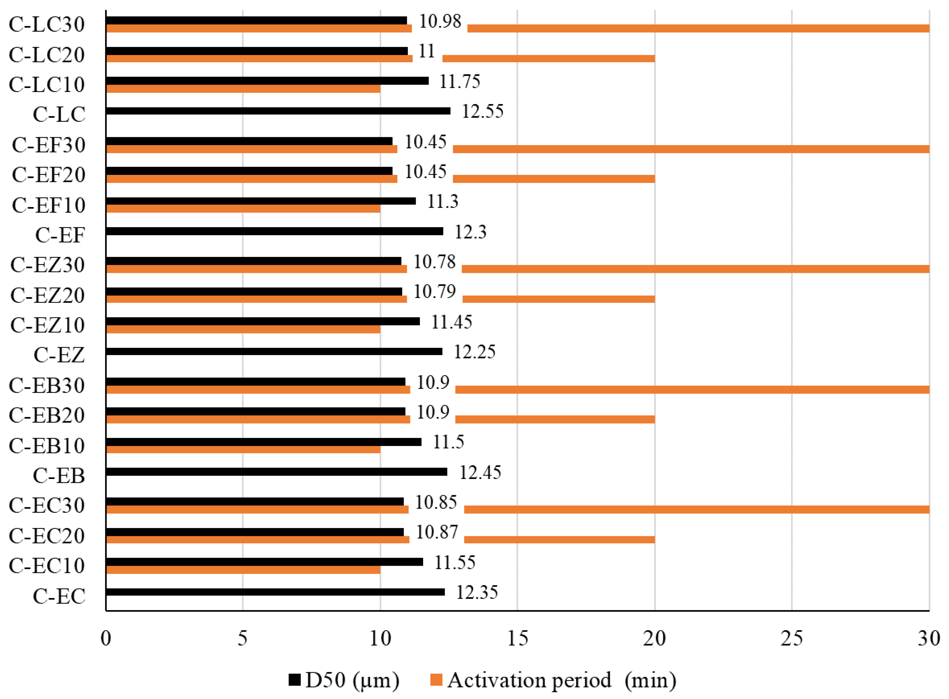
The mechanical pretreatments were conducted for durations of 10, 20, and 30 min (represented by the orange line series in Figure 1). The D50 values are depicted both as a black line series and numerically in Figure 1. As observed, the D50 values stabilized after 20 min of activation.
The prepared mixtures were further homogenized in a laboratory mixer with ethanol for 3 min. After homogenization, the mixtures were shaped into disk specimens measuring approximately 7 mm in thickness and 50 mm in diameter using a laboratory hydraulic press. The resulting samples were then air-dried at 50 °C for 24 h in a laboratory dryer to ensure complete ethanol evaporation and solidification. Once dried, each specimen was placed in a platinum crucible and transferred to a high-temperature furnace (RHF 15/8, Carbolite Furnaces, Sheffield, UK). Sintering was performed at a standard industrial heating rate of 10 °C per minute.

2.3. Instrumental Analyses

The chemical composition of the raw materials was analyzed using energy-dispersive X-ray fluorescence (ED-XRF) on a Spectro Xepos instrument (Spectro Scientific Analytical Instruments, Chelmsford, MA, USA). The XRF system is equipped with a 50 W, 60 V X-ray tube featuring a binary Co/Pd alloy thick target anode, operating in both polarized and direct excitation modes. Elemental emissions from the samples were detected by a silicon drift detector cooled via a Peltier system. For analysis, samples were pulverized to a median particle size of less than 63 μm. Prior to grinding with a Herzog vibratory disk mill (HERZOG Maschinenfabrik GmbH & Co. KG, Osnabrück, Germany), the raw materials were dried at 100 °C in a laboratory oven. Loss on ignition (LoI) was measured at 1000 °C using a laboratory furnace.
Differential thermal analysis (DTA) and thermogravimetric analysis (TG) were performed on the raw meal mixtures using a SETSYS TG/DTA/DSC Simultaneous Thermal Analyzer (Setram Instrumentation, Caluire-et-Cuire, France). The samples were placed in alumina crucibles and subjected to heating from 20 °C to 1000 °C at a constant rate of 10 °C per minute under static air conditions.
X-ray diffraction (XRD) analysis of the sintered cement clinkers was carried out using a Rigaku SmartLab X-ray powder diffractometer (Rigaku Corporation, Tokyo, Japan) equipped with Bragg–Brentano parafocusing geometry and CBO optics with a BB slit (BlueOptics, Mülheim a. d. Ruhr, Germany). A ceramic copper X-ray tube with a long fine focus (LFF) served as the radiation source, operated at 40 kV and 30 mA. Data were collected with a D/teX Ultra 250 strip detector (Rigaku Corporation, Tokyo, Japan) over a 2θ range of 4° to 65°, with a step size of 0.01° and a scan speed of 0.5 min/° 2θ.
Fourier Transform Infrared (FTIR) spectroscopy was conducted on the sintered cement clinkers using a Thermo Fisher Scientific Nicolet IS-50 spectrometer (Thermo Fisher Scientific Inc., Waltham, MA, USA). The attenuated total reflectance (ATR) method was employed to record spectra within the 4000–400 cm−1 range, using 64 scans at a resolution of 2 cm−1. Post-processing steps included automatic baseline correction and atmospheric interference suppression.
Scanning Electron Microscopy (SEM) analyses of sintered cement clinkers were performed using an eLine Plus system (SEM Instrumentation Technology RAITH, Dortmund, Germany) equipped with an energy-dispersive X-ray spectroscopy (EDS) detector (QUANTAX, Bruker, Billerica, MA, USA) to facilitate detailed surface characterization. This instrument is capable of high-resolution electron beam writing across a full 100 mm area, making it suitable for applications such as nanolithography, large-area imaging, material deposition, and etching. The system achieves minimum beam currents of 1.5 nA at 20 kV and 3.4 nA at 1 kV. Prior to imaging, all samples were coated with a gold/palladium alloy using a Denton Desk V sputter coater (Denton Vacuum LLC, Moorestown, NJ, USA).

2.4. Preparation of Cement Samples and Preliminary Testing of the Mechanical Strengths

Experimental cement formulations were prepared by blending 95 wt.% ground clinker with 5 wt.% calcium sulfate dihydrate (gypsum) for 10 min using a laboratory mixer, in accordance with EN 197-1:2013 standards. The gypsum, sourced from Brenntag d.o.o. in Belgrade, Serbia, was of analytical reagent grade. The resulting cements underwent a two-stage grinding process to ensure a homogeneous particle size distribution, comparable to that of commercial OPC CEM I 42.5R (Holcim Srbija d.o.o., Beočin, Serbia). Initially, the cement samples were milled in a Pulverisette 6 classic line planetary mono mill (Fritsch, Karben, Germany) at rotational speeds up to 650 rpm. The powders were then sieved to achieve a particle size distribution between 0.1 and 50 μm and a specific surface area (SSA) of approximately 2250 cm2/g, matching that of the commercial OPC used. The SSA was determined using the Blaine air permeability method.
Cement mortar samples were prepared in accordance with the procedures specified in EN 1015-2:2008 [41]. The strength development of mortars produced with C-EC, C-EB, C-EZ, C-EF, and C-LC cements was evaluated and compared to that of mortar based on OPC (CEM I 42.5R).
The experimental cements and standard quartz sand aggregate were mixed at a 1:3 ratio. The water-to-cement ratio (w/c) was maintained at 0.5 throughout the preparation. Dry components were homogenized using a laboratory pan mixer (Controls S.p.A., Milan, Italy) for 120 s. Water was incrementally added during mixing to achieve self-flowing consistency, while maintaining a fixed w/c of 0.5. The fresh mortar mixtures were cast into steel molds with dimensions of 40 × 40 × 160 mm. Molds were sealed in polyethylene bags and cured at a controlled temperature of 20 ± 2 °C and relative humidity of 95 ± 5% for 48 h. Following demolding, samples were stored under the same conditions for an additional 5 days, then transferred to an environment maintained at 20 ± 2 °C and 65 ± 5% relative humidity until the 28th day.
Compressive and flexural strengths were determined using a hydraulic press (Alfred J. Amsler & Co., Schaffhausen, Switzerland) in accordance with the standard testing procedure outlined in EN 1015-11:2019 [42]. A continuous load was applied at a rate of 50 N/s to ensure that failure occurred between 30 and 90 s. The maximum load recorded during testing (in N) was used to calculate the respective strength values. All reported results represent the mean values obtained from three specimens.

3. Results and Discussion

3.1. Thermal Analysis

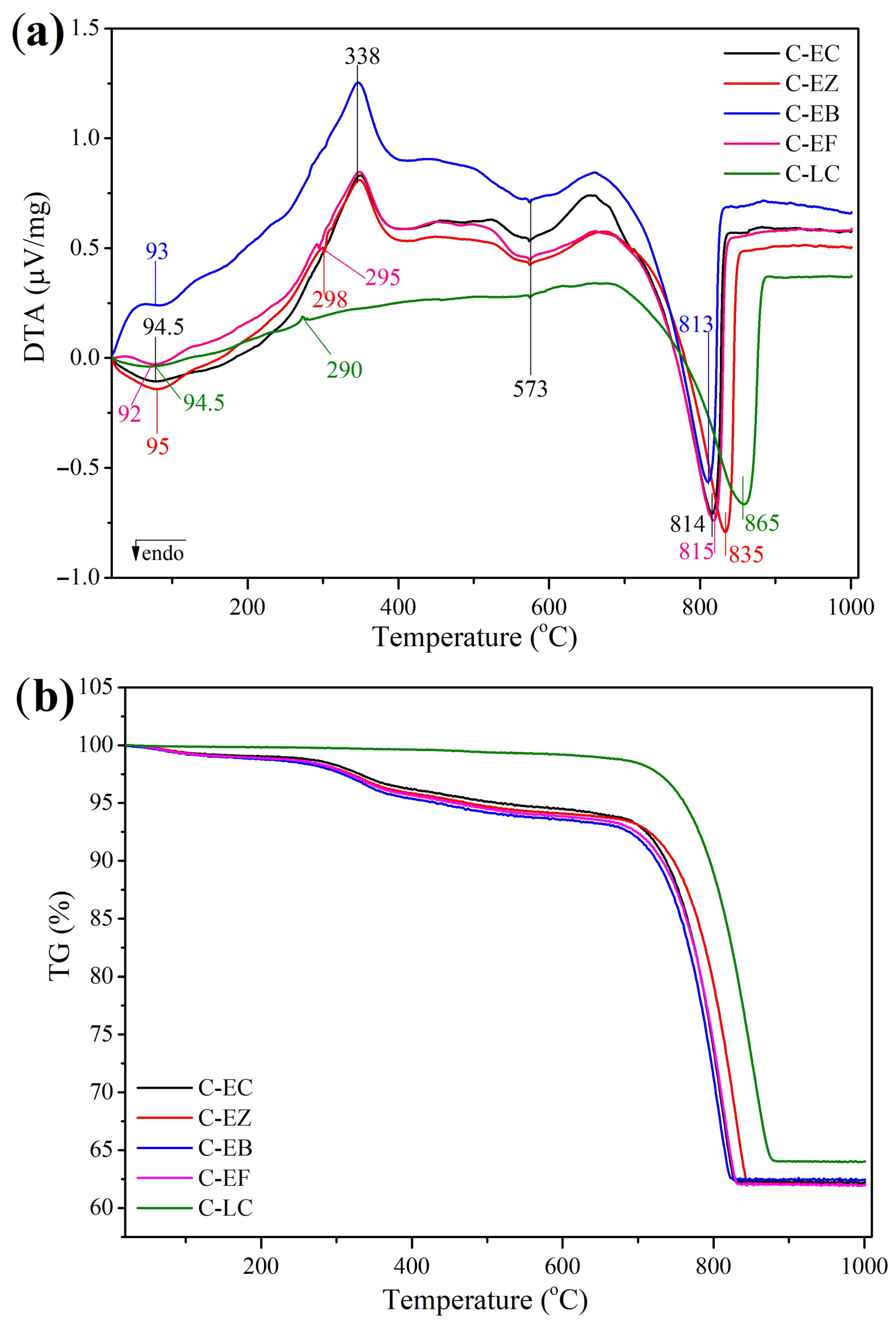
The kiln process simulation was evaluated using thermal analysis and the X-ray diffraction technique. The formation of cement clinker is a multi-stage thermal procedure within the kiln that encompasses sequential steps, including the evaporation of free water, calcination, i.e., decomposition of CaCO3 into CaO and CO2, and sintering at elevated temperatures, during which clinker minerals are formed through solid-state and liquid-phase reactions. Therefore, the raw meals of ESP-based (C-EC, C-EB, C-EZ, and C-EF) and limestone-based (C-LC) clinkers were submitted to DTA/TG analyses to confirm that they adequately correspond to the selected thermal treatment up to 1000 °C. The resulting DTA and TG curves are presented in Figure 2a,b.
As shown in Figure 2a, the DTA curves of ESP-based samples exhibit similar profiles. The C-LC curve does not show the exothermic peak at 338 °C, but rather a gradual background exothermic hump. The DTA curves for ESP-based mixes are divided into four sections: (1) 20–200 °C, (2) 200–500 °C, (3) 500–700 °C, and (4) 700–1000 °C. The C-LC raw mix lacks the second interval, which appears merged with the first section.
Section-1 (20–200 °C) in Figure 2a, corresponds to the initial heating stage, primarily associated with water evaporation from the raw feed. Free water typically evaporates below 60 °C, while bound water release depends on the bonding mechanism. Weakly bound water begins to evaporate around 60 °C and is entirely removed by 108 °C [43]. The mineralogy predominantly governs the temperature and rate of water release. Endothermic minima for both ESP- and LS-based samples occurred below 100 °C, with peak intensities being from 0.05 to 0.125 µV/mg, indicating low water content in the initial feed and, therefore, appropriate raw material preparation. In the C-EZ sample, the minimum occurred at 95 °C. This effect is correlated with the zeolite presence in the mix design. Zeolite exhibits a significant endothermic effect in the 20–250 °C interval, usually around 80 °C [44]. This effect corresponds to the removal of surface water, weakly bound adsorption or capillary-condensed water, and water associated with extra-framework cations [45]. The C-EB curve displays a minimum at 93 °C with a bend near 105 °C, followed by an exothermic hump. The initial endothermic effect related to the presence of bentonite in the mix design corresponds to the dehydration of adsorbed water on external surfaces or interlayer water within montmorillonite layers [46]. This effect takes place in the 30–300 °C interval as a single broad endotherm, but sometimes has shoulders (as seen in C-EB) or double peaks, indicating gradual water loss over the temperature range [47]. Both C-EC and C-LC exhibited minima at 94.5 °C, which is correlated with the inclusion of KI clay in the mix design. KI clay has a distinct broad endothermic peak, corresponding to the loss of physically bound water between 20 °C and 200–250 °C due to the evaporation of moisture and adsorbed water from clay surfaces and pores. Illite releases physically bound water in multiple steps (72 °C and 186 °C), whereas kaolin typically exhibits one or two maxima near 55 °C [48]. For C-EF, the minimum is observed at 92 °C. Water release from fly ash is characterized by a significant endothermic peak in the 25–300 °C interval, corresponding to the evaporation of free and physically bound water from particle surfaces and cavities [49]. The lower temperature of water release in C-EF compared to other samples can be attributed to the significant porosity of fly ash particles, which accelerated evaporation.
Section-2 (200–500 °C) corresponds to dehydration (the release of chemically bound water; 350–400 °C), followed by dehydroxylation (removal of chemically bound water; 450–500 °C). The peak at 290 °C in the C-LC sample can be correlated with a minor exothermic reaction, i.e., the oxidation of organic matter in KI clay (often in the 200–400 °C range) [50]. The C-EF sample exhibited exothermal maxima at 295 °C, which can be correlated with fly ash. This peak is generally associated with the decomposition of organic matter, unburned carbon, or volatile organic compounds that are adsorbed on the surface of the fly ash particles in the 250–350 °C range [51]. The exothermic effect observed in C-EB at 298 °C is associated with the evaporation or desorption of physically bound water from the pores and crystal surfaces of the zeolite [45]. Endothermic valleys recorded at 400–450 °C for C-EC, C-EB, C-EZ, and C-EF samples correspond to dehydroxylation. The temperature range of dehydroxylation varies with clay mineral type; for instance, kaolinite dehydroxylates at 400–700 °C [52]. The dehydroxylation of zeolite takes place at 400–500 °C [44], and for bentonite (primarily montmorillonite), it occurs between 400 °C and 800 °C [46]. In fly ash, this effect is ascribed to iron oxide dehydroxylation, specifically goethite (β-FeOOH) [51]. An exothermic peak at 338 °C is evident in C-EC, C-EB, C-EZ, and C-EF samples. This exothermic peak observed at approximately 338 °C in the DTA of eggshell powder is likely related to the decomposition or combustion of organic matter (proteins and membranes) present in the eggshell [53,54,55].
The temperature interval of 500–700 °C corresponds to Section-3. The effect observed at 573 °C across all DTA curves is commonly attributed to the α- to β-quartz polymorphic transition [35,36].
The main endothermic effect in Section 4 (700–1000 °C) is the decomposition of CaCO3 [56], i.e., the release of CO2 from limestone or eggshell: CaCO3(s) = CaO(s) + CO2 (g). Pure CaCO3 typically decarbonates at atmospheric pressure around 894 °C. However, when this reaction occurs in proximity to quartz or decomposition products of clay minerals, which react with the forming CaO, the decomposition temperature decreases to 500–600 °C [57]. Under experimental conditions, calcination was observed within a narrow temperature range of 836–848 °C, dependent on the CaCO3 content and the presence of other mineral phases. ESP-based raw meals exhibited lower calcination temperatures than C-LC, as seen in Figure 2a.
Mass loss, as determined from TG curves (Figure 2b), can be systematically divided into four distinct stages, consistent with those identified via DTA. The initial stage, corresponding to the evaporation of adsorbed and structural water within the temperature range of 20–200 °C, results in relatively minor mass losses of approximately 2.0%, 2.1%, 2.2%, and 2.3% for samples C-EC, C-EZ, C-EB, and C-EF, respectively. The C-LC sample exhibits a lower mass loss, measuring less than 1%. In the second stage, mass loss increases slightly, with values of 2.7%, 2.8%, 2.9%, and 3.0% recorded for C-EC, C-EZ, C-EB, and C-EF, respectively, while the C-LC sample shows a mass loss of 2.0%. The third stage follows a similar trend, with mass losses of 2.3%, 2.1%, 2.4%, and 2.7% for C-EC, C-EZ, C-EB, and C-EF, respectively, and 1.5% for C-LC. The most pronounced mass loss occurs during the fourth stage, associated with the calcination process: 31.0%, 31.0%, 30.5%, and 30.0% for C-EC, C-EZ, C-EB, and C-EF, respectively. The C-LC sample exhibits a slightly higher mass loss of 33.5% in this stage. Overall, the cumulative mass loss for samples C-EC, C-EZ, C-EB, and C-EF is approximately 38%, marginally exceeding the total mass loss observed for C-LC, which is recorded at 37%.
Thermogravimetric analysis and differential thermal analysis revealed that raw mixes incorporating eggshell powder (ESP) display thermal behavior and mass loss profiles closely aligned with those of conventional limestone-based formulations during cement clinker synthesis. The variations in the onset and magnitude of thermally induced transformations, as well as the mass losses among samples C-EC, C-EZ, C-EB, and C-EF, were minimal. These negligible discrepancies substantiate that calcium sourced from eggshell calcite engages effectively with the aluminum, silicon, and iron present in other mineral phases, thereby facilitating the formation of clinker minerals through mechanisms analogous to those observed in traditional systems. This finding underscores the capacity of Ca derived from eggshell calcite to interact efficiently with Al, Si, and Fe from alternative raw material sources. Moreover, the pronounced similarity in thermal performance up to 1000 °C between ESP-based and limestone-based samples further demonstrates that eggshell powder constitutes a viable and effective substitute for limestone in cement clinker production.

3.2. X-Ray Diffraction Analysis

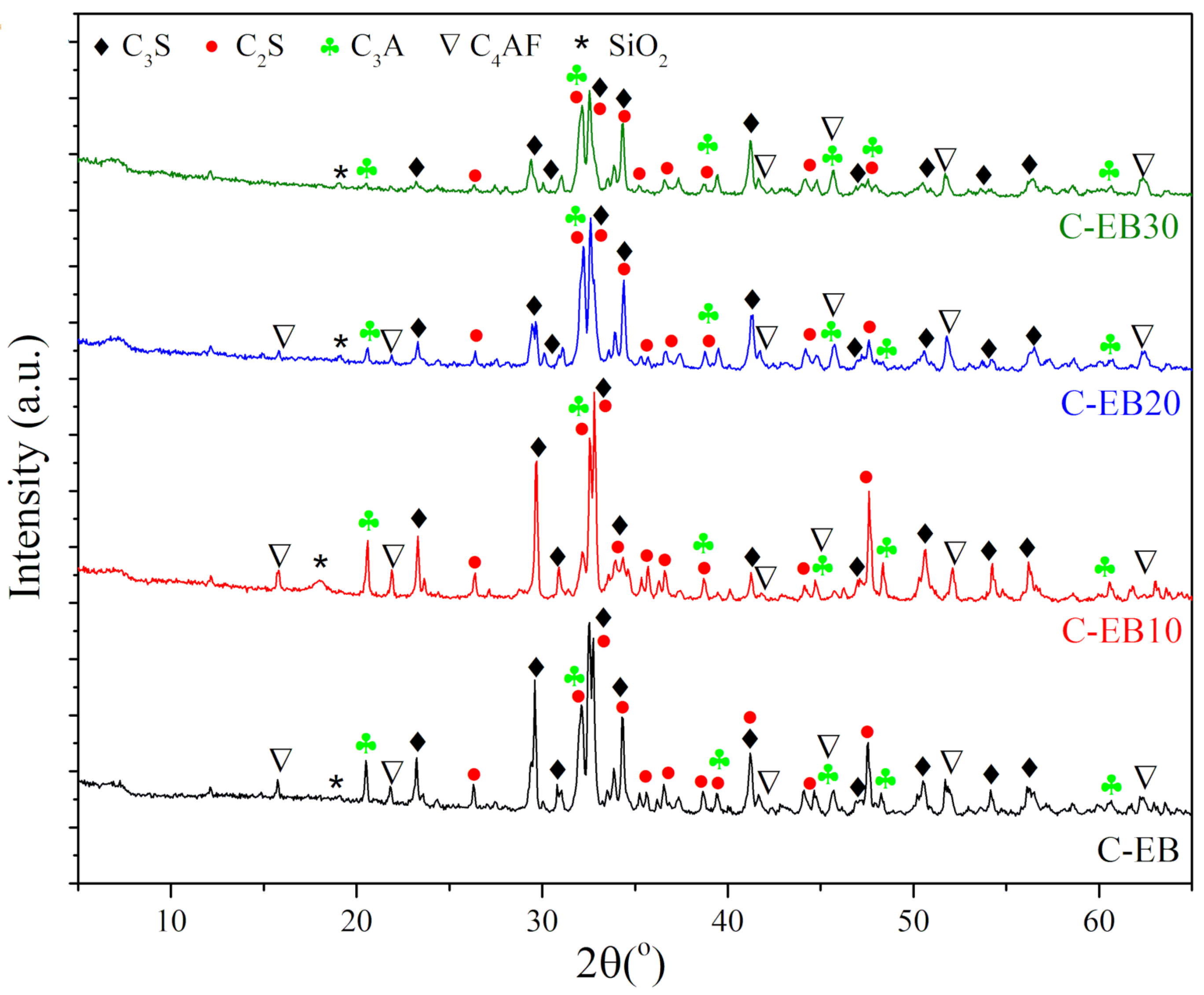
The kiln phase and the development of the four principal cement minerals were evaluated through qualitative XRD analysis (Figure 3 and Figure 4). Figure 5 depicts the phase distribution and comparison for all examined clinkers. In the absence of detailed Rietveld refinement, peak intensities are expressed in arbitrary units (a.u.) for descriptive and comparative purposes. Based on the literature [58,59], the expected quantitative distribution of cement minerals is: tricalcium silicate (C3S) 50–60% (Equation (4)), dicalcium silicate (C2S) 20–25% (Equation (5)), tricalcium aluminate (C3A) 6–10% (Equation (6)), and tetracalcium aluminoferrite (C4AF) 6–10% (Equation (7)):
2CaO·SiO2(s) + CaO(s/L) ⟶ 3CaO·SiO2(s); (or C2S + C ⟶C3S); (T = 1400–1450 °C)
2CaO·SiO2 + CaO ⟶ CaO2SiO4; (C2S); (T = 1000–1400 °C)
3CaO·Al2O3 + CaO ⟶ Ca3Al2O6; (C3A); (T = 1100–1300 °C)
4CaO + Al2O3 + Fe2O3⟶ 4CaO·Al2O3·Fe2O3; (C4AF); (T = 900–1200 °C/up to 1400 °C)
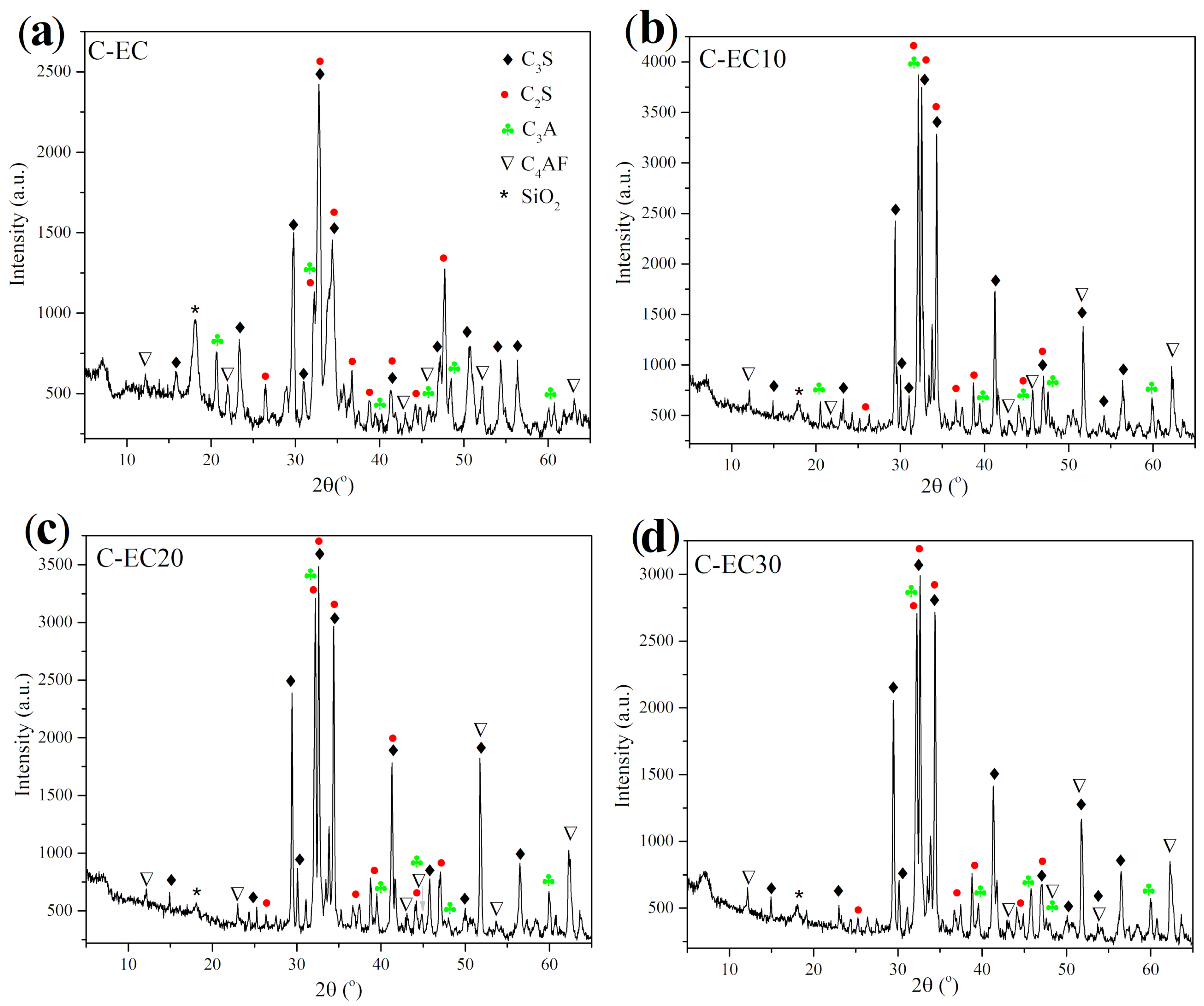
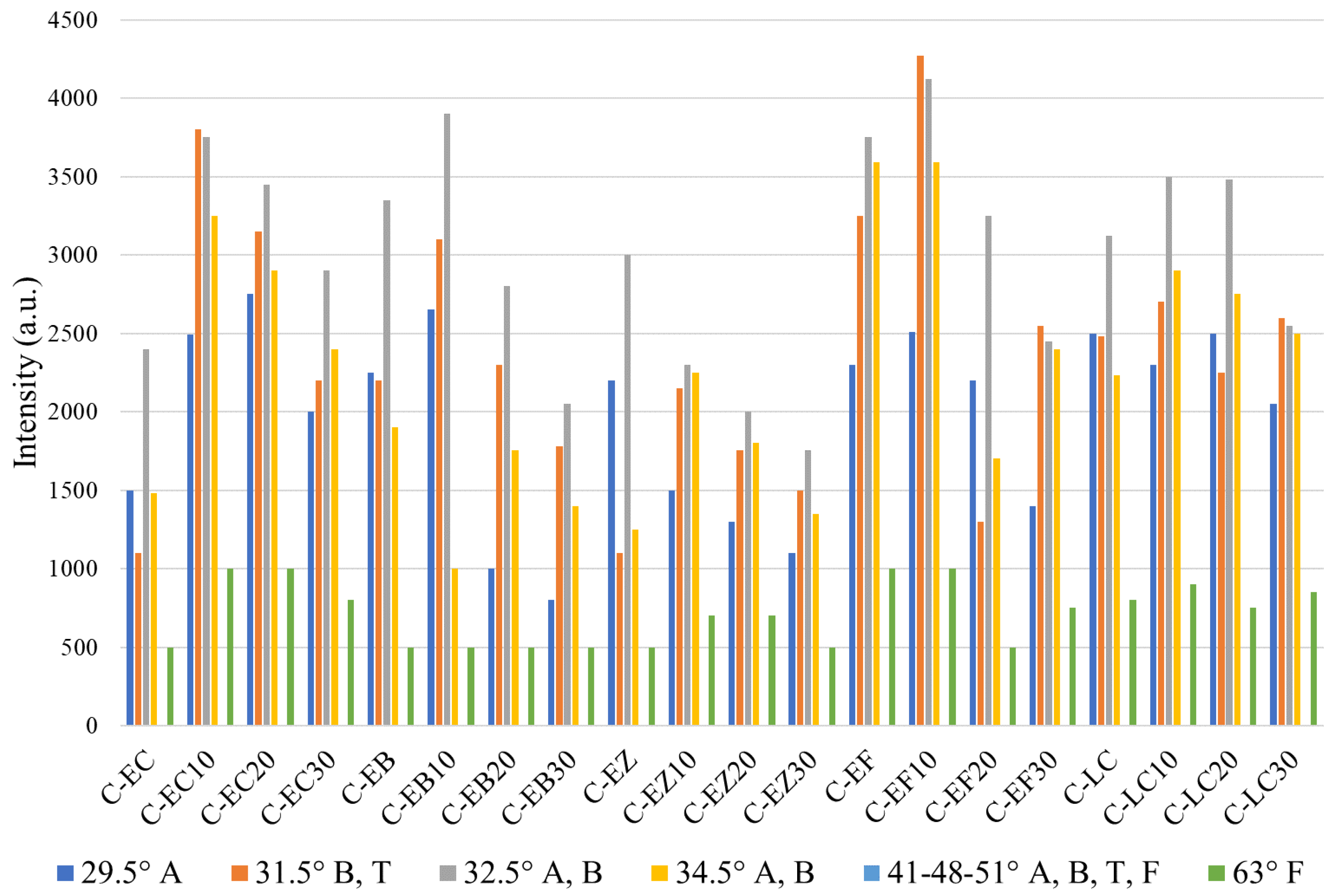
The detailed XRD patterns of the C-EC group of samples are presented in Figure 3a–d. The two predominant mineral phases identified in the initial C-EC sample (Figure 3a) are C3S (JCPDS 86-0402) and C2S (JCPDS 32-0302). The presence of C3S and C2S indicates that the chemical interactions (Equations (4) and (5)) among the raw materials at 1300 °C resulted in clinkerization of the raw feed comprising ESP and KI clay. According to established practices and the literature [9,58,60], high-quality cement clinker requires an adequate alite content, as it imparts primary cementitious properties and is critical for the strength development of cementitious materials during hydration. Conversely, belite contributes predominantly to the long-term strength of cement. Although less reactive than alite, belite remains essential for overall cement performance, including durability characteristics [61,62]. The most prominent C3S reflections in the C-EC clinker are observed at 29.5°, with approximate intensities of 1500 a.u., 32.5° (2400 a.u.), and 34.5° (1480 a.u.). This conclusion is consistent with the literature findings [63], which revealed strong C3S reflections in the 32° to 34° range. Among these, only the reflection at 29.5° appears as a distinct, singular peak. Additional C3S reflections are detected in wide range from 16° to 56°, all exhibiting relatively low intensities (750 a.u.). Dominant C2S reflections are found superimposed with C3S at 32.5° and 34.5°. The literature suggests that belite peaks are generally located between 5° and 40°, with typical reflections at 32° and 34° 2θ [63]. C2S reflections of lower intensity are identified at 26° and within the 35° to 45° range. A comparatively strong C2S reflection is observed at 48° (1280 a.u.). The peak at 31.5° (1100 a.u.) corresponds to a combined reflection of C2S and C3A. In XRD analysis of cementitious materials, the region around 31.5–33.5° is critical for identifying major anhydrous phases, particularly C2S and C3S, which often overlap with C3A [64].
C3A (JCPDS 33-0251) and C4AF (JCPDS 89-2827) found in the C-EC sample had a lower distribution, commensurate with the literature suggesting that these minerals normally calculate up to roughly 6–10% each [58,59]. C3A is the most reactive cement phase, significantly influencing the early hydration kinetics and rheological properties of cementitious materials [65]. In the C-EC sample (Figure 3a), the C3A phase is presented by a singular reflection at 20.5° (750 a.u.). Low-intensity reflections attributable to C3A are detected within the 40° to 50° interval, and around 60°. C4AF plays a vital role by affecting strength, color, and setting time. While it influences hydration and cement properties, its contribution to strength is less significant than that of C3S and C2S [66]. Reflections corresponding to C4AF are identified in C-EC as a series of minor peaks distributed throughout the scanned 2θ range, specifically at 12°, 22°, 43°, 46°, 52°, and 63°. In XRD analyses of cement, C4AF displays peaks particularly noticeable within the 29° to 35° 2θ range, where they superimpose with C3S and C2S [66]. These peaks are often high-angle reflections connected with the particular crystal structure of the material [67]. Quartz (SiO2) reflection was observed near 17°. Other mineral phases were either not detected or present only in trace amounts, likely due to weak reflections or overlapping signals from dominant minerals.
The C3S and C3S + C2S reflections observed in the C-EC10 sample (Figure 3b) are stronger than the corresponding reflections found in the initial C-EC sample: 29.5° (2490 a.u.), 32.5° (3750 a.u.), and 34.5° (3250 a.u.). Two distinct C3S reflections are identified at 41° and 51°, with intensities of 1700 a.u. and 1300 a.u., respectively. The peak at 31.5°, related to the combined reflection of C2S and C3A, is particularly intense (3800 a.u.). Reflections corresponding to C3A and C4AF are detected at the same positions as in the C-EC sample, with intensities near 750 a.u., except the C4AF reflection at 63° which appeared stronger than that of C-EC. In the C-EC20 (Figure 3c) and C-EC30 (Figure 3d) samples, the most prominent XRD peaks appear at the same positions as those observed in two previously analyzed ESP-KI+ clay samples; however, variations are noted in the intensities of the reflections (Figure 5). The primary C3S and C3S + C2S reflections (29.5°, 32.5°, and 34°) exhibit lower intensities than those of C-EC10, as well as the reflections corresponding to C2S and C3A. Alite/alite + belite peaks at 41° and 51°, with an intensity of 1750 a.u. in C-EC20, were marginally stronger compared to C-EC10; however, these peaks decreased to 1300 a.u. and 1100 a.u. in C-EC30. Despite the reductions, the intensities remained higher than those of the C-EC sample. Notably, the intensities of both alite and belite peaks diminished progressively with increasing duration of mechanical pretreatment. These findings corroborate reports in the literature [68], which suggest that short-duration mechanical treatments can enhance the abundance of reactive cement minerals. Moreover, short-term mechanical activation presents an additional advantage in terms of energy efficiency, as it facilitates a reduction in the sintering temperature [69,70,71,72].
Figure 4 provides a comparative analysis of the XRD diffractograms for the C-EB sample. XRD diffractograms for the C-EZ, C-EF, and C-LC sample groups are provided as Supplementary Materials and illustrated in Figures S2–S4.
Figure 5 depicts a review of the positions of the principal peaks in all of the experimental cement clinkers.
The C-EB clinker (Figure 4 and Figure 5) exhibited a high degree of structural similarity to the C-EC sample. The main XRD reflections corresponding to C3S and C3S + C2S are found at 2θ angles of 29.5°, 32.5°, and 34.5°, with respective intensities of 2250 a.u., 3350 a.u., and 1900 a.u. The intensities notably exceed those recorded for the C-EC sample. A distinct reflection at 31.5°, attributed to the merged reflections of C2S and C3A phases, showed 2200 a.u. intensity, approximately double that of the C-EC sample, suggesting improved phase development. Additional C3S and C2S reflections were detected at 41° and 51°, respectively, each with intensities near 1250 a.u. Reflections corresponding to C3A and C4AF were also identified. The C-EB10 sample demonstrated significantly enhanced intensities of 29.5°, 31.5°, and 32.5° reflections, measuring 2650 a.u., 3100 a.u., and 3900 a.u., respectively. The reflection at 34.5°, corresponding to C3S + C2S, was markedly diminished (1000 a.u). Prolonged activation (20–30 min) led to a decrease in reflections intensities, with values of 1000, 2300, and 2800 a.u. at the respective angles for C-EB20, and 800, 1780, and 2050 a.u. C-EB30. The reflections corresponding to C3S + C2S at 34.5° exhibited higher intensities in these two samples, measuring 1750 a.u. and 1400 a.u., respectively. The C-EB10 sample has a prominent C2S peak at 48° (2100 a.u.), followed by a C3S peak at 51° (1200 a.u.). Both C-EB30 and C-EB20 displayed an intense C3S peak at 41° (1200 a.u.). Extended activations of 20 and 30 min negatively influenced the intensity of the reflections recorded in the ESP–bentonite samples. The optimal crystallographic characteristics were observed in the C-EB10 sample, which demonstrated improved phase development and peak intensities compared to C-EB and C-EC clinkers.
The C-EZ clinker (Figure 5 and Figure S2) demonstrated a high degree of similarity to C-EC and C-EB. The principal reflections corresponding to C3S and C3S + C2S were observed at 29.5°, 32.5°, and 34.5°, with intensities of 2200 a.u., 3000 a.u., and 1250 a.u., respectively. These intensities are generally higher than those recorded for the C-EC sample, but lower than the corresponding reflection intensities of C-EB. The reflection attributed to C2S + C3A at 31.5° (1100 a.u.) closely matched the analogous peak in the C-EC sample. A prominent C2S peak (1750 a.u.) was detected at 48°. The ESP–zeolite clinker activated for 10 min exhibited increased intensities of reflections at 29.5°, 31.5°, 32.5°, and 34.5°: 1500, 2150, 2300, and 2250 a.u., respectively. Longer activations resulted in a decrease in the intensities of the observed reflections—1300, 1750, 2000, and 1800 a.u. at the respective angles for the C-EZ20 sample, and 1100, 1500, 1750, and 1350 a.u. for the C-EZ30 sample. All activated samples displayed relatively strong alite and belite reflections at 41° and 51°, replacing the 48° peak observed in the non-activated C-EZ sample. In this group of clinkers, optimal results were achieved with the C-EZ10 sample.
The XRD reflections of the C-EF clinker (Figure 5 and Figure S3) correspond to C3S and C3S + C2S at 29.5°, 32.5°, and 34.5°, with intensities of 2300, 3750, and 3590 a.u., respectively. The values are higher than those observed in all starting samples (C-EC, C-EB, and C-EZ). The reflection at 31.5°, attributed to C2S + C3A, exhibits the highest intensity of 3250 a.u. Additionally, peaks at 41°, 48°, and 51° show intensities of 2000, 750, and 1500 a.u., respectively, representing the most prominent signals among all non-activated samples. Activation for 10 min (C-EF10) increased peak strength, with values of 2510, 4270, 4120, and 3590 a.u. at 29.5°, 31.5°, 32.5°, and 34.5°, respectively, the highest recorded values in this investigation. Corresponding peaks at 41°, 48°, and 51° also increased to 2400, 1000, and 1750 a.u. Prolonged activation beyond 10 min resulted in a significant decrease in peak intensities, particularly at 31.5°, which dropped to 1300 a.u. in the C-EF20 sample. Reflections at 29.5°, 32.5°, and 34.5° decreased to 2200, 3250, and 1700 a.u., respectively, while peaks at 41°, 48°, and 51° fell to 750, 1580, and 1000 a.u. Further activation for 30 min (C-EF30) maintained this tendency, with intensities of 1400, 2550, 2450, and 2450 a.u. at 29.5°, 31.5°, 32.5°, and 34.5°, respectively, and 1550, 750, and 1050 a.u. at 41°, 48°, and 51°. These findings suggest that a 10 min activation interval maximizes phase development in the ESP–fly ash cement clinker. Overall, ESP–fly ash clinkers outperformed the other eggshell-based cements tested in this study.
The initial C-LC sample (Figure 5 and Figure S4), with its main reflections at 29.5°, 31.5°, 32.5°, and 34.5° being 2500, 2480, 3125, and 2230 a.u., respectively, exhibits better mineralogical attributes than its ESP-based equivalent. Furthermore, the peak intensities recorded at 41°, 48°, 51°, and 63° (500, 2200, 1100, and 800 a.u., respectively) were also markedly higher in the C-LC sample compared to C-EC. However, when benchmarked against clinkers derived from ESP combined with alternative clayey materials (C-EB, C-EZ, and C-EF), the phase distribution and intensities of reflection in C-LC and other experimental clinkers were comparable. These findings suggest that the integration of industrial byproducts and/or alternative primary raw materials with bio-based waste holds significant potential as a substitute for conventional cement clinker mixtures utilized in OPC production.

3.3. FTIR Analysis

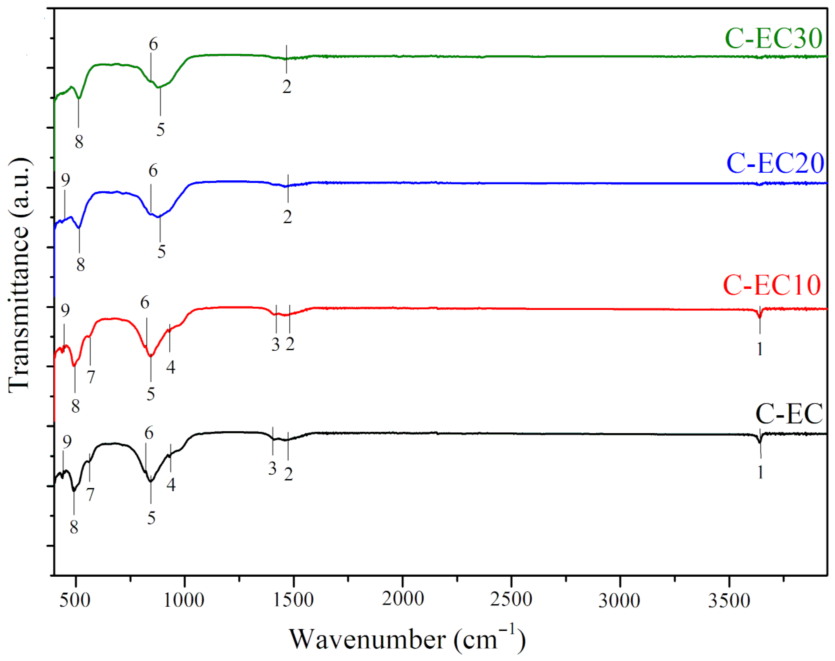
The results of the FTIR analysis of C-EC clinker group conducted within the 4000–400 cm−1 wavelength range are illustrated in Figure 6. The FTIR spectra of the C-EB, C-EZ, C-EF, and C-LC groups of clinker samples are provided as Supplementary Material in Figures S5, S6, S7 and S8, respectively. The complicated spectrum correlations seen among the groups are expected due to the variable oxide content of the samples (Table 1) and extensive overlapping and superposition of crystalline phases detected by XRD (Figure 3 and Figure 4, and Figures S2–S4).
Several differences and similarities among the tested samples are noticeable in the FTIR spectra. Peak-1 (P-1) is a tiny reflection near 3600 cm−1 that appears in all analyzed samples, as seen in Figure 6. Table 4 shows P-1’s precise position, which ranges from 3630 cm−1 (C-EC and C-EC10) to 3650 cm−1 (C-EZ, C-EF, and C-EF10). Samples subjected to mechanical pretreatment for 20 and 30 min lack this reflection. The 3600–4000 cm−1 region of cement clinker spectra usually reveals both free and hydrogen-bonded hydroxyl groups [73,74]. The band near 3600 cm−1 is generally attributed to free O–H. Considering the chemical composition of the raw feed (Table 1), this reflection is likely associated with Al–OH groups, which exhibit characteristic absorption bands within the 3200–3700 cm−1 range [74]. In the zeolite spectra, bands around 3600 cm−1 are primarily ascribed to O–H groups, specifically acidic bridging hydroxyl groups (Si–OH–Al) [75]. In the bentonite spectra, this region is attributed to structural hydroxyls coordinated to octahedral cations such as aluminum (Al–Al–OH) [76]. Kaolin has a characteristic band near 3620 cm−1, while illite shows a similar peak around 3621 cm−1, both attributed to OH vibrations [77]. In fly ash, the peak or broad band near 3600 cm−1 is generally linked to hydroxyl (O–H) stretching vibrations, with intensity and position influenced by source, processing, and moisture content [78]. Finally, in limestone spectra, a peak near 3600 cm−1 signifies the presence of hydroxyl (O–H) groups, while pure CaCO3 (calcite) exhibits characteristic bands in the 1420 cm−1, 875 cm−1, and 710 cm−1 regions [79].
The 1400–1500 cm−1 region is predominantly characterized by reflections attributed to CaCO3 [79,80]. The peak P-2 (at 1490 cm−1) is present in all clinkers except those based on bentonite and fly ash, which are mechanically pretreated for 20 and 30 min (Table 4). This band corresponds to the vibration of the carbonate ion (C–O) derived from CaCO3. In a monophasic system, the C–O band appears at 1420 cm−1 [79]. This band can be associated with the calcite from either the ESP or limestone used in clinker production. In the C-EC and C-EC10 samples, C–O bands are observed at 1492 cm−1 and 1495 cm−1, as well as at 1475 cm−1 (P-3). The splitting of this band might suggest a slight distortion of the carbonate groups and indicate an amorphous state [81,82]. In the zeolite spectrum, the 1400–1500 cm−1 region corresponds to carbonate-related bands [75]. This area is also part of the bentonite “fingerprint” region (below 1500 cm−1), where a lot of single-bond vibrations take place [76]. For fly ash, the 1400–1500 cm−1 region predominantly indicates the presence of carbonate ions (CO32−) and Si–O–T bonds (where T represents Si or Al). A strong band in this region can be attributed to Si-O-T stretching, showing a higher concentration of Si and Al minerals, while a peak near 1400 cm−1 suggests the presence of carbonate [78]. Within this spectral region, illite exhibits a characteristic splitting of the v4 vibrational mode, often manifesting as a doublet, attributable to CO32− impurities. Kaolinite lacks a significant absorption band in this region [77]. The presence of Al, Si and C bonds in the FTIR spectra can be related to the formation of the main cement minerals (C2C, C3S, and C3A) identified as intense reflections in spectral range of 31.5–34.5° of XRF diffractograms (Figure 2).
The 700–900 cm−1 region comprises P-4, P-5, and P-6. The wavelengths are extremely overlaid, making it difficult to identify precise bands. As previously noted, pure calcite exhibits characteristic reflections near 875 cm−1 and 710 cm−1. P-5 and P-6 can be partially correlated with these bands. Specifically, P-5 is observed in the FTIR spectra of all samples within the range of 830 to 869 cm−1 (Table 4, Figure 6 and Figures S5–S8 in the Supplementary Materials). P-6 is slightly shifted toward higher wavenumbers compared to pure CaCO3, ranging from 780 to 792 cm−1. These bands are characteristic of calcite and correspond to the out-of-plane and in-plane bending vibrations of the carbonate group [83]. Additionally, reflections near 900 cm−1 (P-4), detected in all ESP–bentonite, ESP–zeolite, and limestone-clay-based samples, as well as in C-EC, C-EC10, and C-EF, can be attributed to asymmetric stretching Si–O vibrations within the C2S structure. The strong reflection observed at approximately 840 cm−1 (P-5) in all samples can be assigned to the symmetric stretching of Si–O in C2S [83,84]. In the C3S structure, symmetric Si–O stretching vibrations typically appear as a broad absorption band or a set of bands centered between 890 and 955 cm−1 [84]. Both C3S and C2S minerals are identified in XRD analysis (Figure 2). Consequently, P-4 can also be partially attributed to Si–O in C3S. This band is present in all samples except C-EC20, C-EC30, C-EF20, and C-EF30, indicating that mechanical pretreatment in these clinkers did not enhance C3S formation during the high-temperature kiln reactions, as can be seen by decrease in the reflection intensities in the XRD diffractograms of the samples mechanically treated for 20 and 30 min. Al-O vibrations in C3A occur at certain frequency ranges: stretching (700–950 cm−1) and bending (300–550 cm−1) [84]. Therefore, P-4, P-5, and P-6 may also be associated with asymmetric stretching of Al–O vibrations in C3A. Furthermore, an absorption band attributed to the Fe–O in C4AF is typically observed near 700 cm−1, serving as an indicator of the presence of C4AF within the complex clinker material [81]. In the analyzed clinkers, this band likely overlaps with calcite bands at 710 cm−1. Overall, the bands identified within the 700–900 cm−1 region confirm the presence of the principal cement mineral phases, primarily C4AF identified by XRD in the spectral range of 40–48° and around 60°.
Bands observed at wavenumbers below 600 cm−1 are typically attributed to the bending vibrations of Si-O bonds. The peak near 560 cm−1 corresponds to O-Si-O bending vibrations in silicate tetrahedra, which are found in alite and belite. Additionally, the band observed around 500 cm−1 corresponds to the bending modes of the SiO4 tetrahedral groups, encompassing both symmetric and antisymmetric bending vibrations [83,84]. All examined clinkers showed bands characteristic for C3S and C2S phases at low wavenumbers, at about 490 cm−1. These spectral features indicate symmetric bending vibrations of the Si-O bonds inside the crystal structures of C3S and C2S, which further confirms their presence in the clinker matrix.

3.4. Microstructural Identification

Figure 7 and Figure 8 present SEM micrographs of the clinkers labeled C-EF, C-LC, C-EF10, and C-LC10. These samples, representing ESP–fly ash and limestone–KI clay clinker systems, were chosen based on XRD and FTIR analyses. C-EF and C-EF10 exhibited the highest concentrations of cement clinker minerals, while C-LC and C-LC10 displayed mineralogical profiles closely resembling those of the OPC clinker. Accordingly, the SEM images of these clinkers are considered representative of the particle size distribution and morphological features of the principal cement clinker mineral phases. EDS analyses further validated the elemental composition and spatial arrangement of the main mineral phases on the surfaces of the C-EF, C-LC, C-EF10, and C-LC10 samples.
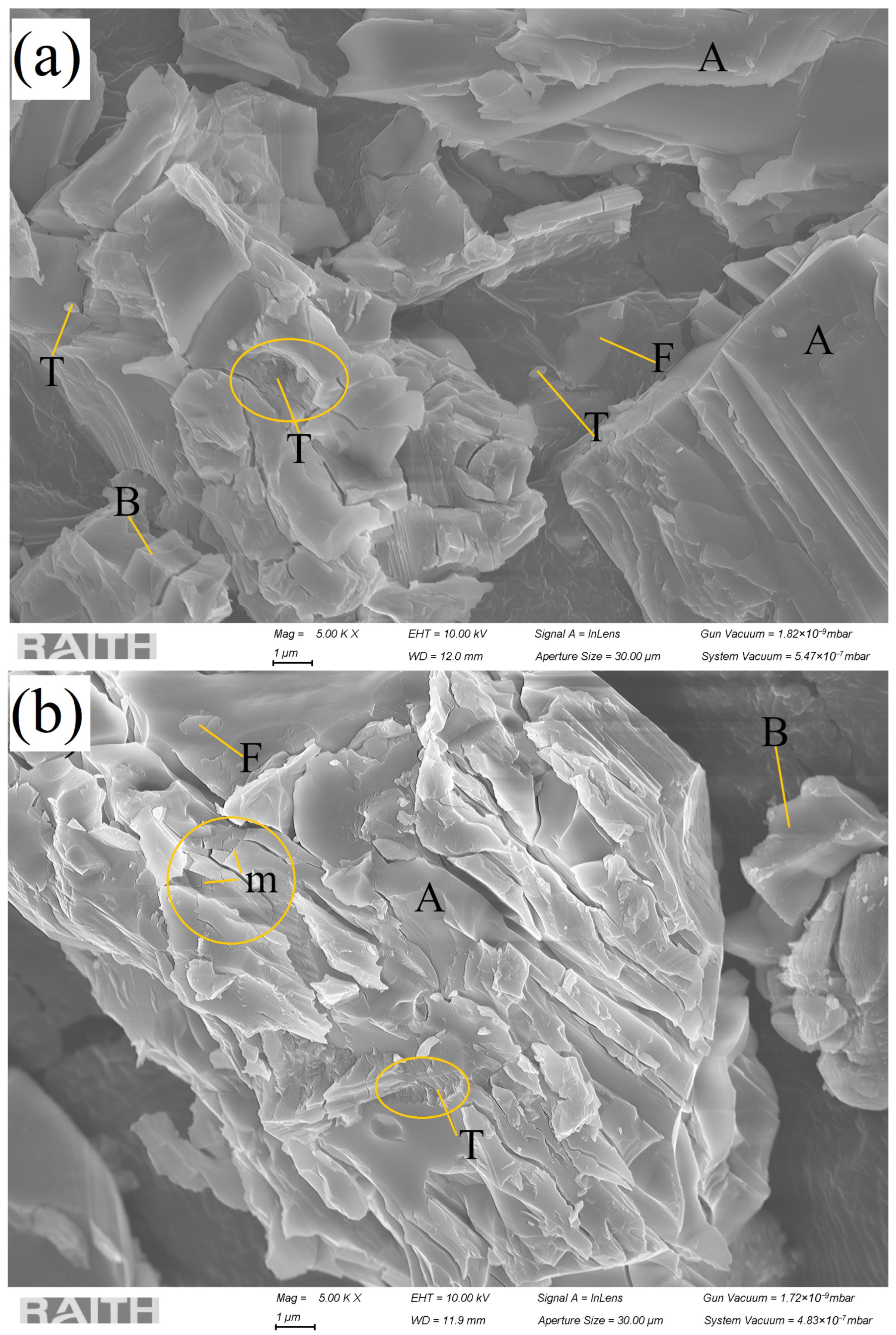
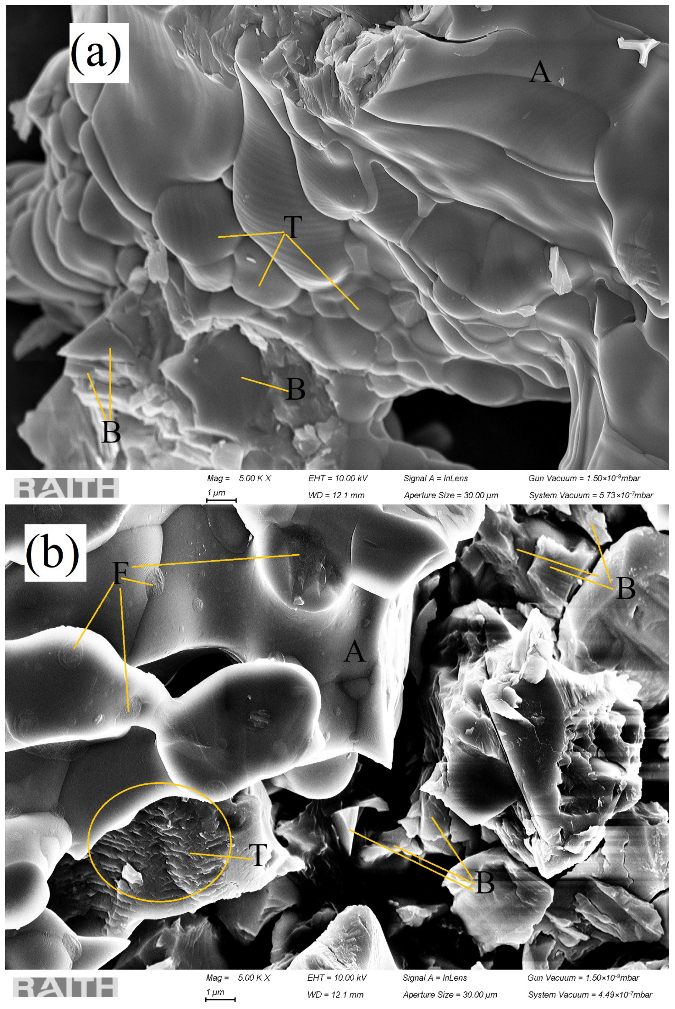
As shown in Figure 7, the synthesized cement clinkers comprise a diverse array of mineral grains with varying sizes and morphologies. The clinkers were examined in their pre-pulverized state, resulting in the observation of agglomerated particle clusters. XRD analysis identified C3S (A) and C2S (B) as the predominant mineral phases, followed by C3A (T) and C4AF (F). Consistent with previous studies, C3S constitutes approximately 50–60% of the clinker, confirming its status as the dominant phase in all samples analyzed. According to the literature [85], C3S grains typically exhibit irregular shapes with sharp edges and sizes ranging from 20 to 30 µm. The grain size and morphology are influenced by factors such as synthesis temperature, cooling rate, and grinding techniques, including mechanical pretreatment. For instance, elevated sintering temperatures generally produce larger grains, while grinding results in finer, more irregular particles that often display micro-cracks [85].
The C-EF clinker (Figure 7a) is primarily composed of prismatic C3S grains with sharp, irregular edges. Due to the high magnification (5000×), only a partial view of these large grains is visible; their estimated length ranges from 15 to 20 µm, aligning with the literature’s values [85]. These alite grains are substantial and compact, indicating complete synthesis at 1300 °C. The grains are intergrown with smaller formations and inclusions corresponding to other mineral phases. Although rapid cooling during clinker formation is known to induce micro-cracks [85], such defects are absent in the observed C3S grains, suggesting effective cooling control (i.e., rapid cooling to ambient temperature using forced air). In the C-LC clinker (Figure 7b), C3S grains are comparable in size to those in C-EF, with one notably large prismatic grain measuring approximately 30 µm in length. This grain consists of a conglomerate of multiple mineral phases with C3S as the primary constituent. The prismatic and predominantly thick morphology of this alite grain corroborates previous findings [85,86]. While C3S grains in C-EF remain compact and intact, micro-cracks (indicated as “m” in Figure 7b) are evident in the C-LC clinker, suggesting suboptimal cooling conditions for limestone-based clinkers. Belite grains (denoted as B in Figure 7) exhibit considerable variability in size and morphology, dependent on clinker production and cooling conditions, consistent with previous findings for alite. Distinct polymorphic forms of C2S possess unique crystal structures, as illustrated in Figure 7. Typically, C2S diameters range from a few µm to several tens of µm. The average grain size of belite is usually near 20 µm [87]. In the present samples, individual C2S grains did not exceed 5 µm, as estimated from Figure 7a,b. Crystal growth of C2S is normally influenced by raw material composition and kiln firing parameters. Here, the inclusion of mechanical pretreatment and sintering and cooling protocols affected the morphology and size distribution of belite grains. Rapid clinker cooling promoted the formation of smaller and distorted crystals, which exhibit enhanced chemical reactivity according to the literature [88]. In the OPC clinker, C3A (denoted as T) forms part of the interstitial phase and exhibits size and shape variability influenced by cooling and sintering conditions. The C3A phases, observed in both C-EF and C-LC samples (Figure 7), appear as clusters of very small particles. C3A grains typically display well-defined, isometric crystal morphologies, such as spherical or orthorhombic dodecahedrons [89]. Figure 7 reveal clusters of very small ovoid grains. C3A grain sizes generally range from approximately 15 to 20 µm, but can be as small as 1 µm or less, depending on synthesis and preprocessing methods [89]. In the observed C-EF and C-LC samples, individual grains measure less than 1 µm, while clusters span several micrometers. C4AF (denoted as F in Figure 7) is characterized by variable grain size and morphology, influenced by chemical composition and processing conditions, i.e., grain size is affected by the liquid-phase content during clinkerization, which governs the eutectic point and crystal morphology. Consequently, C4AF grain shapes are heterogeneous, largely determined by the Al-to-Fe ratio. Within the OPC clinker, C4AF exists as an interstitial phase among larger silicate crystals, with particle sizes between 10 and 50 µm [90]. Figure 7a (sample C-EF) displays a C4AF crystalline solid merged with an alite structure measuring 4–5 µm in length, while Figure 7b shows C4AF as an ellipsoidal inclusion within an alite grain approximately 1 µm in length.
Cement clinkers C-EF10 and C-LC10, depicted in Figure 8a,b, exhibit all four principal cement mineral phases: large C3S grains serve as the matrix for C2S, C3A, and C4AF inclusions. C2S grains measure approximately 5 micrometers or less in size. Distinct C3A clusters are evident in both C-EF10 and C-LC10. Additionally, ellipsoidal C4AF inclusions are prominently observed in Figure 8b. The initial raw feed underwent mechanical activation for 10 min, resulting in a decreased average grain size relative to non-activated samples. This grain size reduction enhanced material reactivity, consistent with findings reported in previous studies [35,36]. XRD analysis revealed intensified peaks corresponding to all four major cement minerals, which supported SEM observations of clearer phase differentiation. The absence of micro-cracks on C3S grains suggests that the sintering temperature and cooling regime were optimally controlled for C-EF10 and C-LC10. No evidence of excessive C2S clustering, which typically indicates slow cooling, was detected. Furthermore, C2S nests, often associated with coarse raw feed rich in siliceous components, were not observed.
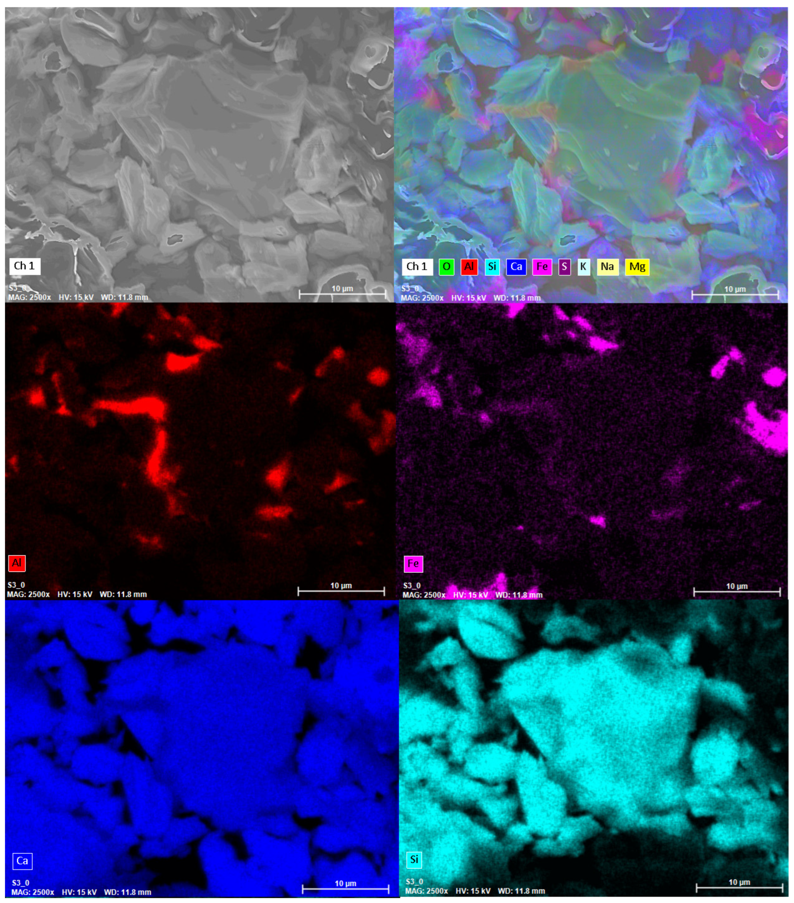
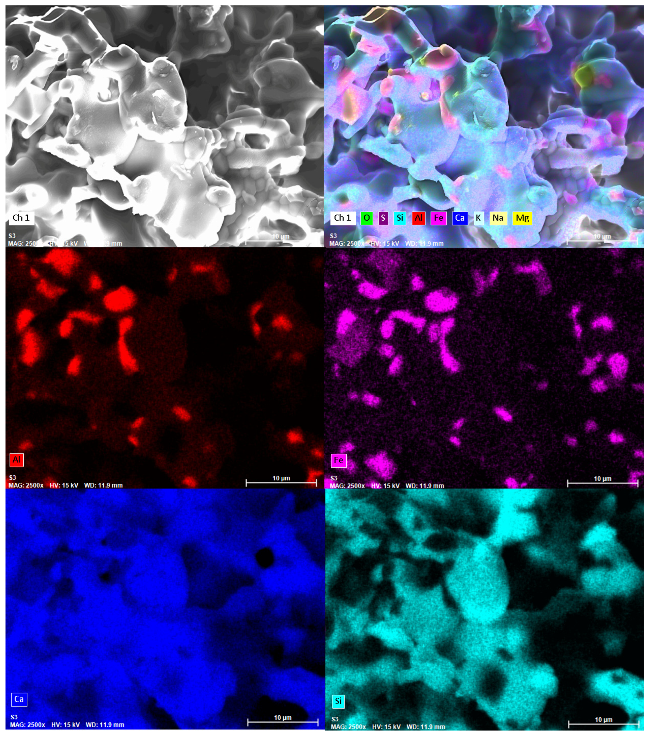
Energy-dispersive X-ray spectroscopy (EDS) was utilized to perform targeted surface chemical analyses of aluminum (Al), calcium (Ca), silicon (Si), and iron (Fe) on samples C-EF, C-LC, C-EF10, and C-LC10. The EDS results for C-EF and C-EF10 are shown in Figure 9 and Figure 10, while the findings for C-LC and C-LC10 are provided in the Supplementary Materials as Figures S9 and S10.
It should be noted that EDS has inherent limitations, such as low sensitivity for detecting light elements (atomic number less than 11), restricted energy resolution, and challenges in accurately quantifying trace elements. Consequently, elemental data obtained from EDS should be interpreted qualitatively or, at best, semi-quantitatively. Additionally, factors such as variations in sample thickness, surface roughness, overlapping X-ray peaks, and the analysis of unpolished materials, including original clinker grains, can introduce potential inaccuracies.
The identification of mineral phases present or predominant in the analyzed grains (Figure 9 and Figure 10, Figures S9 and S10) is based on estimated elemental compositions derived from EDS data. Quantitative elemental compositions are summarized in Table 5.
The data confirmed the presence of principal cement minerals, C3S, C2S, C3A, and C4AF, within the investigated C-EF, C-LC, C-EF10, and C-LC10 clinkers. Calcium was the most abundant element across all samples, exhibiting a relatively uniform distribution consistent with its major role in C2S and C3S phases. Specifically, Ca concentrations ranged from 42 to 49% in the selected samples, as detailed in Table 5. The EDS spectra for the C-EF, C-EF10, C-LC and C-LC10 samples are provided in the Supplementary Materials as Figures S11, S12, S13, and S14, respectively.
Aluminum, iron, and silicon were also detected as significant constituents. These elemental distributions align well with observations from the SEM micrographs (Figure 7 and Figure 8) and corroborate the microstructural characteristics of the samples. Furthermore, microstructural analysis supports prior findings obtained through DTA/TG, FTIR, and XRD analyses, confirming that ESP can effectively substitute limestone in the cement clinker mix design.

3.5. Mechanical Strengths of Experimental Cements

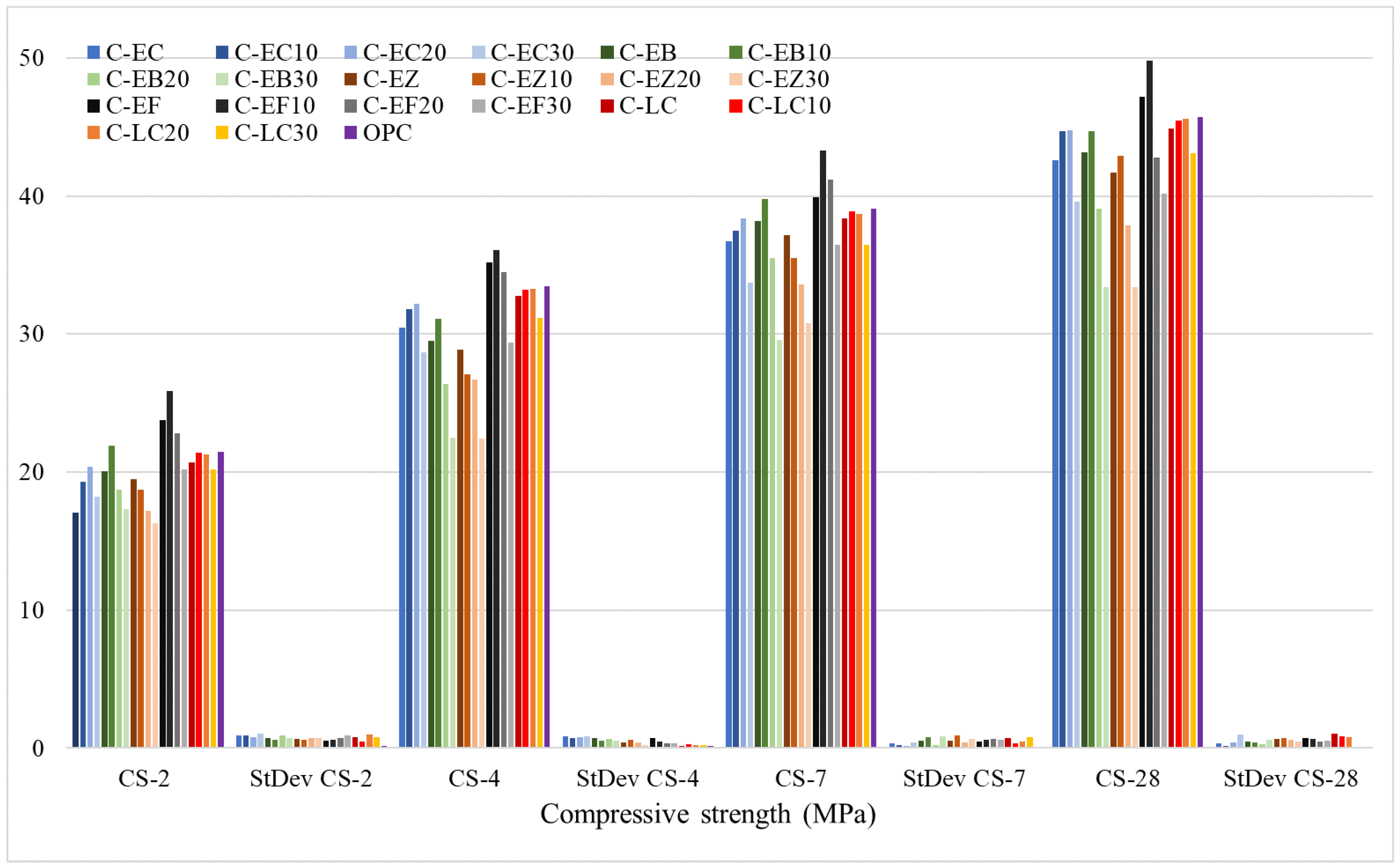
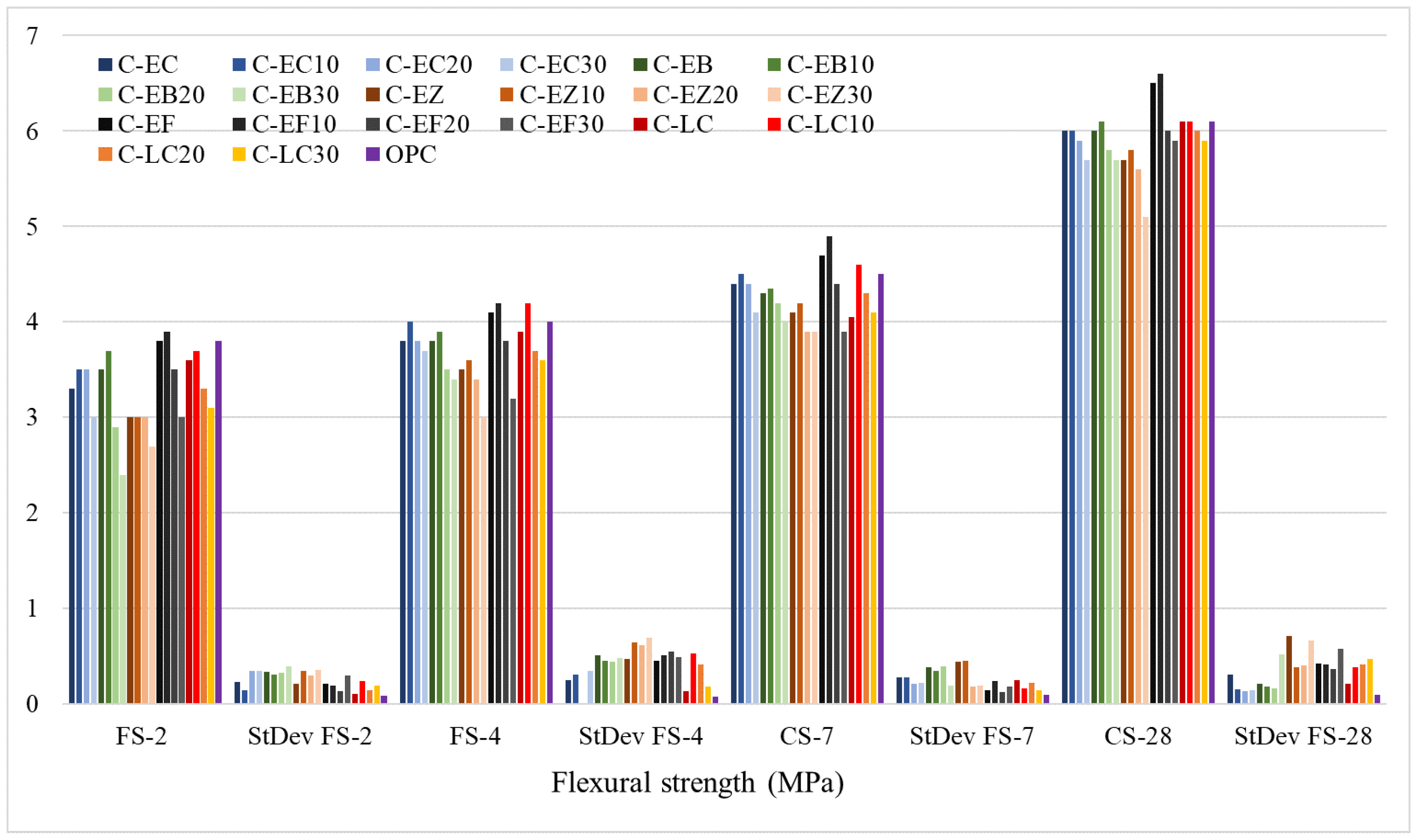
Figure 11 and Figure 12 show the compressive and flexural strengths of mortar samples made from experimental cements following the procedure described in Section 2. This study evaluates and validates mechanical properties using ASTM C311’s 75% reference strength criterion. Samples with strengths more than 75% of OPC mortar’s standard strength can be used for structural applications; otherwise, the materials are considered for non-structural applications.
As demonstrated in Figure 11, the early compressive strengths (CS-2) of ESP–fly ash cements (C-EF, C-EF10 and C-EF20) and the ESP–bentonite sample activated for 10 min (C-EB10) outperformed those of OPC. Limestone-based cements C-LC10 and C-LC20 demonstrated slightly lower CS-2 values of 21.4 and 21.3 MPa, respectively. Other samples exhibited compressive strengths below that of OPC. The maximum CS-2 was observed in C-EF10 at 25.9 MPa, approximately 17% higher than OPC’s 21.5 MPa. The lowest CS-2 was recorded for the ESP–zeolite cement C-EZ30 at 16.3 MPa, representing a 24% reduction relative to OPC; nonetheless, it still met the minimum threshold of 75% of the reference strength. Overall, all tested cements achieved more than 75% of OPC’s initial compressive strength, satisfying the ASTM criteria for structural applications. Cements made from raw feed pretreated for 20 and 30 min have lower strengths than non-treated and 10 min activated specimens. The observed trends in CS-4 and CS-7 values for the experimental cements closely paralleled those of CS-2. The highest CS-4 strengths were recorded for C-EF (35.2 MPa), C-EF10 (36.1 MPa), and C-EF20 (34.5 MPa), corresponding to increases of 4.9%, 7.7%, and 2.9%, respectively, relative to OPC (33.5 MPa). The CS-4 values for C-EC10 and C-EB10 were approximately 5% lower than OPC, while limestone–KI clay samples C-LC, C-LC10, and C-LC20 exhibited CS-4 values ranging from 32.8 to 33.3 MPa, about 1% lower than OPC. The lowest CS-4 values were observed in C-EB30 (22.5 MPa) and C-EZ30 (22.4 MPa), representing a 33% reduction compared to the reference strength. For CS-7, the highest values were similarly recorded for C-EF (35.2 MPa), C-EF10 (36.1 MPa), and C-EF20 (34.5 MPa), with C-EF10 exceeding OPC (39.1 MPa) by 7.7%. Conversely, C-EB30 exhibited the lowest CS-7 of 29.6 MPa, 24.3% below the reference strength, indicating limited structural applicability due to its proximity to the 25% strength reduction threshold.
DTA/TG and XRD analyses revealed several factors underlying the improved early strength of ESP–fly ash cements. The more rapid release of weakly bound and chemically bonded water in C-EF, compared to conventional KI clays, zeolite, and bentonite, is attributed to the higher porosity of fly ash. This accelerated initial reaction likely modifies subsequent hydration mechanisms, promoting faster hydration kinetics and resulting in enhanced early compressive strength. Mechanical pretreatment for 10 min further elevated performance, as corroborated by XRD patterns showing intensified and sharper peaks for C2S, C3S, C4A, and C4AF phases. Alite, identified as the predominant phase, is primarily responsible for early strength development. ESP substitution for limestone yielded results comparable to C-LC mortars, without compromising initial strength. The use of ESP and fly ash led to higher early age compressive strengths relative to OPC, demonstrating that these raw materials can significantly improve the initial mechanical properties of cement.
The 28-day compressive strength (CS-28) is a standard benchmark, representing approximately 99% of the target design strength. The highest CS-28 was recorded for the C-EF10 sample at 49.8 MPa, exceeding the OPC reference value of 45.7 MPa by 9%. ESP-KI+ clay cements, notably C-EC10 and C-EC20, had comparable strengths of 44.7 MPa and 44.8 MPa, respectively, which were about 2% lower than OPC. Within the ESP–bentonite group, C-EB10 demonstrated the highest strength at 44.7 MPa, corresponding to a 2.2% reduction relative to OPC. The ESP–zeolite cement C-EZ10 achieved a CS-28 of 42.9 MPa, approximately 6% below the OPC benchmark. Lastly, limestone-based cements C-LC10 and C-LC20 showed similar compressive strengths of 45.5 MPa and 45.6 MPa, closely matching the OPC reference. The combined use of fly ash and eggshell significantly enhanced belite production, as indicated by XRD. Belite contributes to the mechanical strength of cementitious materials primarily through its slow hydration kinetics, which promote long-term (late-age) strength development. The use of ESP as a calcite source appears to boost long-term strength improvements by facilitating belite formation. ESP–zeolite and ESP–bentonite cements C-EB30 and C-EZ30 exhibited the lowest CS-28 of 33.4 MPa, representing a 27% reduction compared to the reference OPC. Because of a substantial decrease in strength, they are not suitable for structural applications. The lower mechanical performance is related to a decrease in reactivity caused by extensive mechanical activation.
Figure 12 illustrates the flexural strength development of the experimental cements over 28 days. At 2 days (FS-2), C-EF and C-EF10 exhibited strengths of 3.8 and 3.9 MPa, comparable to OPC (3.8 MPa). The lowest FS-2 strength was observed in C-EB30 (2.4 MPa), representing a 37% reduction relative to OPC. By 4 days (FS-4), C-EF and C-EF10 surpassed OPC, achieving 4.1 and 4.2 MPa versus 4.0 MPa for OPC, while C-EZ30 recorded the lowest strength at 3.0 MPa, 25% below OPC. At 7 days (FS-7), C-EF and C-EF10 maintained superior performance with strengths of 4.7 and 4.9 MPa, corresponding to increases of 4.4% and 8.9% over OPC, respectively. The lowest FS-7 strength (3.9 MPa) was found in C-EZ30, C-EB30, and C-EF30, showing that extended mechanical activation of raw materials did not improve cement reactivity during sintering or mineral formation, influencing strength growth. Overall, early age flexural strengths of all experimental cements were satisfactory with minimal deviation from OPC. At 28 days (FS-28), the trend remained the same, with C-EF and C-EF10 achieving the highest strengths of 6.5 and 6.6 MPa, exceeding OPC (6.1 MPa) by 6.5% and 8.1%, respectively. The lowest FS-28 strength was recorded for C-EZ30 (5.1 MPa), a 16.3% decrease relative to OPC.
The numerical values of standard deviations and their detailed illustrations are provided in the Supplementary Materials (Tables S1 and S2 and Figures S15 and S16). As the standard deviation quantifies the dispersion of data points around the mean, and given the limited sample size in this study, we refrained from drawing definitive conclusions based solely on this metric. A low standard deviation indicates that data points are closely clustered around the mean, reflecting consistency within the dataset. Conversely, a high standard deviation signifies greater spread and variability among the data points, a concept well established in statistical analysis.
In the present case, the scores are situated near the mean, indicating low variability and, consequently, a higher degree of consistency. It is important to note that with a larger sample size, the statistical analyses would likely yield more robust and meaningful insights, thereby enhancing the significance and reliability of the research findings.
Incorporating ESP instead of limestone, and principally fly ash as a clay substitute, greatly enhances early age and long-term compressive and flexural strengths when compared to OPC. Alternative mixtures with kaolinitic–illitic clay, bentonite, or zeolite combined with ESP showed acceptable mechanical properties over shorter activation times. A 10 min mechanical pretreatment reduced the sintering temperature by about 100 °C while maintaining strong performance. Cements with kaolinitic–illitic clays and limestone also matched the strength of OPC, demonstrating the potential of low-grade clays. Zeolite-based cements met the minimum structural requirements despite lower strengths. Based on mechanical testing alone, it can be elucidated that cements C-EC, C-EC10, C-EB, C-EB10, C-EZ, C-EZ10, C-EF, C-EF10, C-LC, C-LC10, and C-LC20 are suitable for structural concrete, while higher pretreatment samples are better for lower-demand or non-structural use.

3.6. Practical Implementation of Eggshell Waste into Cement Manufacturing Process

Eggshell waste, generated globally at an estimated 6.4 to 8.6 million tons annually, represents a significant environmental challenge. However, this abundant byproduct can be transformed into valuable materials such as bio-derived calcium oxide.
Practical Implementations: Before eggshells can be utilized for industrial purposes, they must undergo a series of essential preprocessing steps to ensure both purity and stability [91]. First, the eggshells are thoroughly cleaned to eliminate any residual egg white and yolk. This is typically followed by sterilization, either through autoclaving or by heating at temperatures between 100 °C and 110 °C, to eradicate potential pathogens and remove the organic membrane lining the shell. Next, the cleaned and dried eggshells are subjected to mechanical processing, most commonly ball milling, to grind them into a fine powder. This increases the surface area, thereby enhancing the material’s reactivity in subsequent applications. Finally, the powdered eggshells undergo calcination, a thermal treatment process conducted at temperatures ranging from 600 °C to 1000 °C. This step converts the calcium carbonate present in the eggshells into highly reactive calcium oxide, making it suitable for use as a solid base catalyst in various industrial processes [92].
Industrial Scalability: Although laboratory-scale research demonstrates considerable potential, transitioning to industrial-scale implementation is feasible but necessitates overcoming challenges related to feedstock management. Notably, approximately 70% of eggshell waste originates from large-scale egg-processing plants, bakeries, and food manufacturing companies. This concentration enables efficient, centralized collection and supports the establishment of continuous, high-volume production systems. Regarding processing methods, research has shown that rotary kiln technology is well-suited for the continuous synthesis of calcium oxide on an industrial scale. These systems can accommodate increased feedstock input while consistently achieving product purities between 96% and 98%, thereby satisfying stringent industrial quality requirements. The scalability of these processes opens up a range of practical applications, such as the incorporation of CaO as a supplementary material in construction (e.g., as a partial substitute for cement in concrete or in cement production), its use in wastewater treatment for adsorption purposes, and its integration into the production of bioplastics and sustainable packaging materials [91,93].
Economic Viability: The repurposing of eggshell waste offers a compelling economic advantage by converting what is typically a costly disposal issue into an affordable and sustainable resource. Regarding a reduction in disposal expenses, organizations often incur substantial expenses for landfill disposal, with costs ranging from 25 to 60 euros per ton. Enhanced value creation is mirrored in transforming eggshell waste into high-value products, such as purified calcium carbonate (CaCO3), catalysts for biodiesel production, and agricultural fertilizers, which generate considerable economic benefits. Also, there are decreased manufacturing costs, because incorporating eggshell powder as a supplementary material in construction applications, including environmentally friendly concrete and ceramic tiles, can notably lower the overall cost of production while maintaining comparable structural performance. Finally, environmental impact is reflected in the fact that this approach results in approximately 40% fewer carbon emissions compared to the conventional synthesis of calcium compounds [94].

4. Conclusions

This study elucidates the viability of synthesizing cement clinkers using eggshell waste and alternative raw materials such as fly ash, zeolite, bentonite, and low-grade kaolinitic–illitic clay at lower sintering temperatures (1300 °C) than the traditional 1400–1450 °C range. This strategy primarily emphasizes the potential for biowaste valorization and eventual energy savings, which can result in increased sustainability in clinker manufacturing.
Comprehensive instrumental characterization of eggshell-based experimental clinkers via DTA/TG, XRD, FTIR, and SEM/EDS demonstrated that the production of the four principal clinker phases (i.e., C3S, C2S, C3A, and C4AF) closely mimics those found in ordinary Portland cement. In phase development, eggshell was found to be a crucial calcite source, which can fully replace limestone in cement production. Zeolite, bentonite, fly ash, and low-grade kaolinitic–illitic as aluminum source materials contributed significantly to C3A and C4AF formation. Their combined effect with calcite from eggshell waste powder influenced the production of C3S and C2S, which in turn enhanced the mechanical strength of the resulting cements at early and late ages.
Mechanical pretreatment of raw materials for a short period of time (10 min) emerged as a critical parameter, allowing clinkerization at lower temperatures and producing clinkers with physico-chemical and mechanical qualities similar to ordinary Portland cement. In contrast, extended mechanical pretreatments had a negative impact on clinker phase development and mechanical performances. Therefore, eggshell-based cements with short activation periods are potentially suitable for structural applications, while cements whose raw feed underwent longer mechanical pretreatments are more appropriate for lower-demanding or non-structural applications.
In summary, this research introduced an innovative and integrative method using alternative raw materials and optimized mechanical pretreatment to produce quality cement clinkers at reduced sintering temperatures. The results highlight opportunities to conserve natural resources and improve resource efficiency in cement manufacturing by valorizing industrial byproducts and waste streams. However, the study is limited to laboratory-scale experiments, which may not directly apply to industrial production. Scale-up studies with kiln replicas and process optimization are necessary to evaluate viability. Future research should focus on the most effective substitute materials, employ advanced techniques (TEM, NMR, quantitative XRD, etc.), and conduct further comprehensive mechanical and durability testing, including long-term performance assessments.

Supplementary Materials

The following supporting information can be downloaded at: https://www.mdpi.com/article/10.3390/su18104959/s1, Figure S1. Flowchart of the experimental procedure; Figure S2. XRD diffractogram of C-EZ; Figure S3. XRD diffractogram of C-EF; Figure S4. XRD diffractogram of C-LC; Figure S5. FTIR spectra of C-EB; Figure S6. FTIR spectra of C-EZ; Figure S7. FTIR spectra of C-EF; Figure S8. FTIR spectra of C-LC; Figure S9. Spatial disposition of selected elements on surface of C-LC clinker; Figure S10. Spatial disposition of selected elements on surface of C-LC10 clinker; Figure S11. EDS spectra for C-EF; Figure S12. EDS spectra for C-EF10; Figure S13. EDS spectra for C-LC; Figure S14. EDS spectra for C-LC10; Figure S15. Standard deviation for compressive strengths; Figure S16. Standard deviation for flexural strengths; Table S1. Standard deviations for compressive strengths; Table S2. Standard deviations for flexural strengths.

Author Contributions

A.T.: Writing—Original Draft, Review and Editing, Investigation, Validation, Methodology, Formal Analysis, Data Curation, Validation, Visualization, and Conceptualization; S.F.: Methodology, Formal Analysis, Visualization, Validation, and Software; J.Ž.: Formal Analysis; A.P.T.: Formal Analysis; I.N.J.: Formal Analysis and Software; N.O.: Methodology, Investigation, and Validation; and W.G.F.: Supervision, Review and Editing, and Validation. All authors have read and agreed to the published version of the manuscript.

Funding

This investigation is financially supported by the Ministry of Science, Technological Development and Innovation of the Republic of Serbia under Contract No.: 451-03-33/2026-03/200012.

Institutional Review Board Statement

Not applicable.

Informed Consent Statement

Not applicable.

Data Availability Statement

The original contributions presented in this study are included in the article. Further inquiries can be directed to the corresponding author.

Conflicts of Interest

The authors declare they have no competing interests or financial conflicts.

Abbreviations

OPCPortland cement
C3STricalcium silicate (alite)
C2SDicalcium silicate (belite)
C3ATricalcium aluminate
C4AF Tetracalcium aluminoferrite
LSFLime saturated factor
SMSilica modulus
AMAlumina modulus
ESPEggshell powder
SCCSelf-compacting concrete
ED-XRFEnergy-dispersive X-ray fluorescence
PSDParticle size distribution
SCMs Supplementary cementitious materials
KI clay Kaolinitic–illitic clay
DTADifferential thermal analysis
TGThermo-gravimetry
XRDX-ray diffraction
FTIR Fourier transform infrared
SEM Scanning electron microscopy
EDSEnergy-dispersive X-ray spectroscopy
AARAlkali-aggregate reaction
ASRAlkali–silica reaction

References

  1. Shivaprasad, K.N.; Yang, H.-M.; Singh, J.K. A path to carbon neutrality in construction: An overview of recent progress in recycled cement usage. J. CO2 Util. 2024, 83, 102816. [Google Scholar] [CrossRef]
  2. Xue, Z.; Zhu, W.; Li, L.; Jiang, C.; Yan, C.; Wang, Y.; Gao, J.; Luo, J. Carbon emissions assessment of cement mixing piles for soft loess improvement and carbon emission reduction using white mud-cement composite material. Case Stud. Constr. Mater. 2024, 21, e03397. [Google Scholar] [CrossRef]
  3. Cao, H.; Han, L.; Liu, M.; Li, L. Spatial differentiation of carbon emissions from energy consumption based on machine learning algorithm: A case study during 2015–2020 in Shaanxi, China. J. Environ. Sci. 2023, 149, 358–373. [Google Scholar] [CrossRef] [PubMed]
  4. Generowicz-Caba, N.; Kulczycka, J. LCA of Cement with Alternative Additives: Pathways to Sustainable Production. Materials 2025, 18, 3057. [Google Scholar] [CrossRef]
  5. Avudaiappan, S.; Munoz, R.F.A.; Murali, G.; Chávez-Delgado, M.; Andres, R.-M.; Manidurai, P.; Flores, E.S.; Maureira-Carsalade, N. Resource recovery for sustainable construction: Strength and microstructure characteristics of municipal solid waste incineration ash as a green alternative to cement in cementitious composites. Case Stud. Constr. Mater. 2025, 24, e05675. [Google Scholar] [CrossRef]
  6. Schneider, M. The cement industry on the way to a low-carbon future. Cem. Concr. Res. 2019, 124, 105792. [Google Scholar] [CrossRef]
  7. Sbahieh, S.; McKay, G.; Nurdiawati, A.; Al-Ghamdi, S.G. The sustainability of partial and total replacement of Ordinary Portland Cement: A deep dive into different concrete mixtures through life cycle assessment. J. Build. Eng. 2025, 108, 112830. [Google Scholar] [CrossRef]
  8. Majhi, R.K.; Shin, S.; Kim, J.; Patro, S.K. Towards sustainable cement: Review of blended binder systems and performance-based specification strategies. Mater. Today Sustain. 2026, 34, 101328. [Google Scholar] [CrossRef]
  9. Taylor, H.F.W. Cement Chemistry; Thomas Telford Ltd.: London, UK, 1997. [Google Scholar] [CrossRef]
  10. Ludwig, H.-M.; Zhang, W. Research review of cement clinker chemistry. Cem. Concr. Res. 2015, 78, 24–37. [Google Scholar] [CrossRef]
  11. Rößler, C.; Zimmer, D.; Trimby, P.; Ludwig, H.-M. Chemical–crystallographic characterisation of cement clinkers by EBSD-EDS analysis in the SEM. Cem. Concr. Res. 2022, 154, 106721. [Google Scholar] [CrossRef]
  12. Schneider, M.; Romer, M.; Tschudin, M.; Bolio, H. Sustainable cement production—Present and future. Cem. Concr. Res. 2011, 41, 642–650. [Google Scholar] [CrossRef]
  13. Scrivener, K.L.; John, V.M.; Gartner, E.M. Eco-efficient cements: Potential economically viable solutions for a low-CO2 cement-based materials industry. Cem. Concr. Res. 2018, 114, 2–26. [Google Scholar] [CrossRef]
  14. Schneider, M. Process technology for efficient and sustainable cement production. Cem. Concr. Res. 2015, 78, 14–23. [Google Scholar] [CrossRef]
  15. Terán-Cuadrado, G.; Tahir, F.; Nurdiawati, A.; Almarshoud, M.A.; Al-Ghamdi, S.G. Current and potential materials for the low-carbon cement production: Life cycle assessment perspective. J. Build. Eng. 2024, 96, 110528. [Google Scholar] [CrossRef]
  16. Mikulčić, H.; Klemeš, J.J.; Vujanović, M.; Urbaniec, K.; Duić, N. Reducing greenhouse gasses emissions by fostering the deployment of alternative raw materials and energy sources in the cleaner cement manufacturing process. J. Clean. Prod. 2016, 136, 119–132. [Google Scholar] [CrossRef]
  17. El-Gamal, S.M.A.; Selim, F.A. Utilization of some industrial wastes for eco-friendly cement production. Sustain. Mater. Technol. 2017, 12, 9–17. [Google Scholar] [CrossRef]
  18. Zhang, J.; Cui, K.; Yang, Y.; Chang, J. Investigation on the preparation of low carbon cement materials from industrial solid waste phosphogypsum: Clinker preparation, cement properties, and hydration mechanism. J. Clean. Prod. 2024, 452, 142203. [Google Scholar] [CrossRef]
  19. Bai, R.; Yan, C.; Zhang, J.; Liu, S.; Jing, L. Microstructural characteristics of aluminosilicate minerals in cement clinker prepared from coal gangue, carbide slag, and desulfurization gypsum. Constr. Build. Mater. 2024, 451, 138861. [Google Scholar] [CrossRef]
  20. Pei, T.; Zheng, Y.; Wang, Y.; Zhang, D.; Zhang, P.; Cui, S.; Zheng, Y.; Zhao, S. Utilization of copper tailings in the preparation of low-calcium Portland cement clinker and carbonation-hardening mechanism. Constr. Build. Mater. 2024, 457, 139362. [Google Scholar] [CrossRef]
  21. Islam, M.S.; Mohr, B.J. Comparison of eggshell powder blended cementitious materials with ASTM Type IL cement-based materials. Cement 2024, 17, 100109. [Google Scholar] [CrossRef]
  22. Grzeszczyk, S.; Kupka, T.; Kałamarz, A.; Sudoł, A.; Jurowski, K.; Makieieva, N.; Oleksowicz, K.; Wrzalik, R. Characterization of eggshell as limestone replacement and its influence on properties of modified cement. Constr. Build. Mater. 2021, 319, 126006. [Google Scholar] [CrossRef]
  23. Faridi, H.; Arabhosseini, A. Application of eggshell wastes as valuable and utilizable products: A review. Res. Agric. Eng. 2018, 64, 104–114. [Google Scholar] [CrossRef]
  24. Oliveira, D.A.; Benelli, P.; Amante, E.R. A literature review on adding value to solid residues: Egg shells. J. Clean. Prod. 2012, 46, 42–47. [Google Scholar] [CrossRef]
  25. Yang, D.; Zhao, J.; Ahmad, W.; Amin, M.N.; Aslam, F.; Khan, K.; Ahmad, A. Potential use of waste eggshells in cement-based materials: A bibliographic analysis and review of the material properties. Constr. Build. Mater. 2022, 344, 128143. [Google Scholar] [CrossRef]
  26. Li, G.; Xu, X.; Chen, E.; Fan, J.; Xiong, G. Properties of cement-based bricks with oyster-shells ash. J. Clean. Prod. 2014, 91, 279–287. [Google Scholar] [CrossRef]
  27. Baláž, M. Ball milling of eggshell waste as a green and sustainable approach: A review. Adv. Colloid Interface Sci. 2018, 256, 256–275. [Google Scholar] [CrossRef]
  28. Paruthi, S.; Khan, A.H.; Kumar, A.; Kumar, F.; Hasan, M.A.; Magbool, H.M.; Manzar, M.S. Sustainable cement replacement using waste eggshells: A review on mechanical properties of eggshell concrete and strength prediction using artificial neural network. Case Stud. Constr. Mater. 2023, 18, e02160. [Google Scholar] [CrossRef]
  29. Hamada, H.M.; Tayeh, B.A.; Al-Attar, A.; Yahaya, F.M.; Muthusamy, K.; Humada, A.M. The present state of the use of eggshell powder in concrete: A review. J. Build. Eng. 2020, 32, 101583. [Google Scholar] [CrossRef]
  30. Shiferaw, N.; Habte, L.; Thenepalli, T.; Ahn, J.W. Effect of eggshell powder on the hydration of cement paste. Materials 2019, 12, 2483. [Google Scholar] [CrossRef] [PubMed]
  31. Binici, H.; Aksogan, O.; Sevinc, A.H.; Cinpolat, E. Mechanical and radioactivity shielding performances of mortars made with cement, sand and egg shells. Constr. Build. Mater. 2015, 93, 1145–1150. [Google Scholar] [CrossRef]
  32. Pliya, P.; Cree, D. Limestone derived eggshell powder as a replacement in Portland cement mortar. Constr. Build. Mater. 2015, 95, 1–9. [Google Scholar] [CrossRef]
  33. Zain, M.R.M.; Oh, C.L.; Lee, S.W. Investigations on rheological and mechanical properties of self-compacting concrete (SCC) containing 0.6 μm eggshell as partial replacement of cement. Constr. Build. Mater. 2021, 303, 124539. [Google Scholar] [CrossRef]
  34. Her, S.; Park, J.; Li, P.; Bae, S. Feasibility study on utilization of pulverized eggshell waste as an alternative to limestone in raw materials for Portland cement clinker production. Constr. Build. Mater. 2022, 324, 126589. [Google Scholar] [CrossRef]
  35. Terzić, A.; Pezo, L.; Mijatović, N.; Stojanović, J.; Kragović, M.; Miličić, L.; Andrić, L. The Effect of Alternations in Mineral Additives (Zeolite, Bentonite, Fly Ash) on Physico-chemical Behavior of Portland Cement Based Binders. Constr. Build. Mater. 2018, 180, 199–210. [Google Scholar] [CrossRef]
  36. Terzić, A.; Radulović, D.; Pezo, L.; Andrić, L.; Miličić, L.; Stojanović, J.; Grigorova, I. The effect of mechano-chemical activation and surface treatment of limestone filler on the properties of construction composites. Compos. Part B Eng. 2017, 117, 61–73. [Google Scholar] [CrossRef]
  37. Wesselsky, A.; Jensen, O.M. Synthesis of pure Portland cement phases. Cem. Concr. Res. 2009, 39, 973–980. [Google Scholar] [CrossRef]
  38. Zepper, J.C.O.; Van Der Laan, S.R.; Schollbach, K.; Brouwers, H.J.H. A Bogue approach applied to basic oxygen furnace slag. Cem. Concr. Res. 2023, 175, 107344. [Google Scholar] [CrossRef]
  39. ASTM C150/C150M-24; Standard Specification for Portland Cement. ASTM International: West Conshohocken, PA, USA, 2024.
  40. EN 197-1: SRPS EN 197-1:2013; Cement-Part 1: Composition, Specifications and Conformity Criteria for Common Cements. European Committee for Standardization: Belgrade, Serbia, 2013.
  41. SRPS EN 1015-2:2008; Methods of Test for Mortar for Masonry-Part 2: Bulk Sampling of Mortars and Preparation of Test Mortars. European Committee for Standardization: Belgrade, Serbia, 2008.
  42. SRPS EN 1015-11:2019; Methods of Test for Mortar for Masonry-Part 11: Determination of Flexural and Compressive Strength of Hardened Mortar. European Committee for Standardization: Belgrade, Serbia, 2019.
  43. Sha, W.; O’Neill, E.A.; Guo, Z. Differential scanning calorimetry study of ordinary Portland cement. Cem. Concr. Res. 1999, 29, 1487–1489. [Google Scholar] [CrossRef]
  44. Narasimhulu, K.; Gettu, R.; Babu, K.G. Beneficiation of Natural Zeolite through Flash Calcination for Its Use as a Mineral Admixture in Concrete. J. Mater. Civ. Eng. 2013, 26, 24–33. [Google Scholar] [CrossRef]
  45. Afzal, M. TG and DTA Study of the Thermal Dehydration of Metal-exchanged Zeolite-4A Samples. J. Therm. Anal. Calorim. 2000, 62, 721–727. [Google Scholar] [CrossRef]
  46. Zivica, V.; Palou, M.T. Physico-chemical characterization of thermally treated bentonite. Compos. Part B Eng. 2014, 68, 436–445. [Google Scholar] [CrossRef]
  47. Önal, M.; Sarıkaya, Y. Thermal behavior of a bentonite. J. Therm. Anal. Calorim. 2007, 90, 167–172. [Google Scholar] [CrossRef]
  48. Kubliha, M.; Trnovcová, V.; Ondruška, J.; Štubňa, I.; Bošák, O.; Kaljuvee, T. Comparison of dehydration in kaolin and illite using DC conductivity measurements. Appl. Clay Sci. 2017, 149, 8–12. [Google Scholar] [CrossRef]
  49. Wu, W.; Matalkah, F.; Darsanasiri, A.G.N.D.; Soroushian, P. Fluidized bed combustion coal fly ash: Comparative evaluation for potential use in alkali-activated binders. Int. J. Coal Prep. Util. 2019, 42, 51–66. [Google Scholar] [CrossRef]
  50. Húlan, T.; Štubňa, I. Young’s modulus of kaolinite-illite mixtures during firing. Appl. Clay Sci. 2020, 190, 105584. [Google Scholar] [CrossRef]
  51. Giergiczny, Z. Effect of some additives on the reactions in fly ASH-Ca(OH)2 system. J. Therm. Anal. Calorim. 2004, 76, 747–754. [Google Scholar] [CrossRef]
  52. Kakali, G.; Perraki, T.; Tsivilis, S.; Badogiannis, E. Thermal treatment of kaolin: The effect of mineralogy on the pozzolanic activity. Appl. Clay Sci. 2001, 20, 73–80. [Google Scholar] [CrossRef]
  53. Cree, D.; Pliya, P. Effect of elevated temperature on eggshell, eggshell powder and eggshell powder mortars for masonry applications. J. Build. Eng. 2019, 26, 100852. [Google Scholar] [CrossRef]
  54. Chen, W.; Wu, Y.; Xie, Z.; Li, Y.; Tang, W.; Yu, J. Calcium hydroxide recycled from waste eggshell resources for the effective recovery of fluoride from wastewater. RSC Adv. 2022, 12, 28264–28278. [Google Scholar] [CrossRef] [PubMed]
  55. Toibah, A.R.; Misran, F.; Shaaban, A.; Mustafa, Z. Effect of pH condition during hydrothermal synthesis on the properties of hydroxyapatite from eggshell waste. J. Mech. Eng. Sci. 2019, 13, 4958–4969. [Google Scholar] [CrossRef]
  56. Kakali, G.; Tsivilis, S.; Kolovos, K.; Voglis, N.; Aivaliotis, J.; Perraki, T.; Passialakou, E.; Stamatakis, M. Use of secondary mineralizing raw materials in cement production. A case study of a wolframite–stibnite ore. Cem. Concr. Compos. 2004, 27, 155–161. [Google Scholar] [CrossRef]
  57. Simoni, M.; Wilkes, M.D.; Brown, S.; Provis, J.L.; Kinoshita, H.; Hanein, T. Decarbonising the lime industry: State-of-the-art. Renew. Sustain. Energy Rev. 2022, 168, 112765. [Google Scholar] [CrossRef]
  58. Li, X.; Shen, X.; Tang, M.; Li, X. Stability of tricalcium silicate and other primary phases in portland cement clinker. Ind. Eng. Chem. Res. 2014, 53, 1954–1964. [Google Scholar] [CrossRef]
  59. Simoni, M.; Hanein, T.; Duvallet, T.Y.; Jewell, R.B.; Provis, J.L.; Kinoshita, H. Producing cement clinker assemblages in the system: CaO-SiO2-Al2O3-SO3-CaCl2-MgO. Cem. Concr. Res. 2021, 144, 106418. [Google Scholar] [CrossRef]
  60. Ravaszová, S.; Dvořák, K. Development of crystallinity of triclinic polymorph of tricalcium silicate. Materials 2020, 13, 3734. [Google Scholar] [CrossRef]
  61. Dahhou, M.; Hamidi, A.E.; Moussaouiti, M.E.; Arshad, M.A. Synthesis and characterization of belite clinker by sustainable utilization of alumina sludge and natural fluorite (CaF2). Materialia 2021, 20, 101204. [Google Scholar] [CrossRef]
  62. Stemmermann, P.; Ullrich, A.; Beuchle, G.; Garbev, K.; Schweike, U. Belite cement clinker from autoclaved aerated concrete waste—A contribution towards CO2-reduced circular building materials. Ce/Papers 2022, 5, 17–26. [Google Scholar] [CrossRef]
  63. Courtial, M.; Noirfontaine, M.; Dunstetter, F.; Gasecki, G.; Signes-Frehel, M. Polymorphism of tricalcium silicate in Portland cement: A fast visual identification of structure and superstructure. Powder Diffr. 2003, 18, 7–15. [Google Scholar] [CrossRef]
  64. Kim, Y.; Lee, S.W.; Rho, H.T.; Kim, S. Hydration and microhardness of mineral trioxide aggregate depending on ratio between di- and tricalcium silicates. Int. J. Appl. Ceram. Technol. 2021, 19, 1605–1612. [Google Scholar] [CrossRef]
  65. Hirsch, T.; Matschei, T.; Stephan, D. The hydration of tricalcium aluminate (Ca3Al2O6) in Portland cement-related systems: A review. Cem. Concr. Res. 2023, 168, 107150. [Google Scholar] [CrossRef]
  66. Ye, S.; Feng, P.; Liu, J. Dissolution and early hydration of tetracalcium aluminoferrite (C4AF) in water and in aqueous sulfate solutions. Cem. Concr. Res. 2024, 186, 107676. [Google Scholar] [CrossRef]
  67. Nagao, M.; Kobayashi, K.; Jin, Y.; Maruyama, I.; Hibino, T. Ionic conductive and photocatalytic properties of cementitious materials: Calcium silicate hydrate and calcium aluminoferrite. J. Mater. Chem. A 2020, 8, 15157–15166. [Google Scholar] [CrossRef]
  68. Bouchenafa, O.; Hamzaoui, R.; Florence, C.; Mansoutre, S. Cement and clinker production by indirect mechanosynthesis process. Constr. Mater. 2022, 2, 200–216. [Google Scholar] [CrossRef]
  69. Csáki, Š.; Štubňa, I.; Dobroň, P.; Minárik, P.; Záleská, M.; Václavů, T.; Vozár, L. Influence of mechanical treatment on thermophysical processes in illitic clay during firing. Appl. Clay Sci. 2017, 141, 240–247. [Google Scholar] [CrossRef]
  70. Mejdoub, R.; Hammi, H.; Khitouni, M.; Suñol, J.J.; M’nif, A. The effect of prolonged mechanical activation duration on the reactivity of Portland cement: Effect of particle size and crystallinity changes. Constr. Build. Mater. 2017, 152, 1041–1050. [Google Scholar] [CrossRef]
  71. Lee, J.; Lothenbach, B.; Moon, J. Performance improvement of Portland-limestone cement by mechanochemical activation. Cem. Concr. Res. 2023, 176, 107411. [Google Scholar] [CrossRef]
  72. Chen, Z.; Lu, S.; Tang, M.; Ding, J.; Buekens, A.; Yang, J.; Qiu, Q.; Yan, J. Mechanical activation of fly ash from MSWI for utilization in cementitious materials. Waste Manag. 2019, 88, 182–190. [Google Scholar] [CrossRef] [PubMed]
  73. Hughes, T.L.; Methven, C.M.; Jones, T.G.J.; Pelham, S.E.; Fletcher, P.; Hall, C. Determining cement composition by Fourier transform infrared spectroscopy. Adv. Cem. Based Mater. 1995, 2, 91–104. [Google Scholar] [CrossRef]
  74. Horgnies, M.; Chen, J.J.; Bouillon, C. Overview about the use of Fourier Transform Infrared spectroscopy to study cementitious materials. WIT Trans. Eng. Sci. 2013, 1, 251–262. [Google Scholar] [CrossRef]
  75. Isernia, L.F. FTIR study of the relation, between extra-framework aluminum species and the adsorbed molecular water, and its effect on the acidity in ZSM-5 steamed zeolite. Mater. Res. 2013, 16, 792–802. [Google Scholar] [CrossRef]
  76. Zhang, H.; Shi, Y.; Xu, X.; Zhang, M.; Ma, L. Structure Regulation of Bentonite-Alginate nanocomposites for controlled release of imidacloprid. ACS Omega 2020, 5, 10068–10076. [Google Scholar] [CrossRef]
  77. Jozanikohan, G.; Abarghooei, M.N. The Fourier transform infrared spectroscopy (FTIR) analysis for the clay mineralogy studies in a clastic reservoir. J. Pet. Explor. Prod. Technol. 2022, 12, 2093–2106. [Google Scholar] [CrossRef]
  78. Das, S.K.; Shrivastava, S. A study on the viability of fly ash and construction and demolition waste as geopolymerized masonry mortar and their comparative analysis. Mater. Today Proc. 2020, 32, 574–583. [Google Scholar] [CrossRef]
  79. Hossain, M.S.; Jahan, S.A.; Ahmed, S. Crystallographic characterization of bio-waste material originated CaCO3, green-synthesized CaO and Ca(OH)2. Results Chem. 2023, 5, 100822. [Google Scholar] [CrossRef]
  80. Hamzaoui, R.; Bouchenafa, O. Equivalent Cement Clinker Obtained by Indirect Mechanosynthesis Process. Materials 2020, 13, 5045. [Google Scholar] [CrossRef]
  81. Król, M.; Koleżyński, A.; Florek, P.; Jeleń, P.; Kozień, D.; Mozgawa, W. Full spectroscopic characterization of clinker minerals (anhydrous cement). J. Mol. Struct. 2022, 1255, 132454. [Google Scholar] [CrossRef]
  82. Cai, G.-B.; Chen, S.-F.; Liu, L.; Jiang, J.; Yao, H.-B.; Xu, A.-W.; Yu, S.-H. 1,3-Diamino-2-hydroxypropane-N,N,N′,N′-tetraacetic acid stabilized amorphous calcium carbonate: Nucleation, transformation and crystal growth. CrystEngComm 2009, 12, 234–241. [Google Scholar] [CrossRef]
  83. Timón, V.; Torrens-Martin, D.; Fernández-Carrasco, L.J.; Martínez-Ramírez, S. Infrared and Raman vibrational modelling of β-C2S and C3S compounds. Cem. Concr. Res. 2023, 169, 107162. [Google Scholar] [CrossRef]
  84. Fernández-Carrasco, L.; Torrens-Martín, D.; Morales, L.M.; Martínez-Ramírez, S. Infrared Spectroscopy in the Analysis of Building and Construction Materials; InTech eBooks: London, UK, 2012. [Google Scholar] [CrossRef]
  85. Stutzman, P. Scanning electron microscopy imaging of hydraulic cement microstructure. Cem. Concr. Compos. 2004, 26, 957–966. [Google Scholar] [CrossRef]
  86. Erdoğan, S.T.; Nie, X.; Stutzman, P.E.; Garboczi, E.J. Micrometer-scale 3-D shape characterization of eight cements: Particle shape and cement chemistry, and the effect of particle shape on laser diffraction particle size measurement. Cem. Concr. Res. 2010, 40, 731–739. [Google Scholar] [CrossRef]
  87. Sokol, E.V.; Kokh, S.N.; Vapnik, Y.; Thiery, V.; Korzhova, S.A. Natural analogs of belite sulfoaluminate cement clinkers from Negev Desert, Israel. Am. Mineral. 2014, 99, 1471–1487. [Google Scholar] [CrossRef]
  88. Chen, X.; Li, J.; Lu, Z.; Ng, S.; Niu, Y.; Jiang, J.; Xu, Y.; Lai, Z.; Liu, H. The role of Brownmillerite in preparation of High-Belite Sulfoaluminate cement Clinker. Appl. Sci. 2022, 12, 4980. [Google Scholar] [CrossRef]
  89. Kása, E.; Szabó, Y.; Szabados, M.; Kukovecz, Á.; Kónya, Z.; Sipos, P.; Kutus, B. The neutralization of tricalcium aluminate hexahydrate and its spontaneous transformation into Friedel’s salt, a layered double hydroxide. Cem. Concr. Res. 2023, 177, 107414. [Google Scholar] [CrossRef]
  90. Zhang, G.; Ren, Q.; He, J.; Jiang, S.; Cheng, X.; Yu, Y.; Huang, S.; Zhang, C.; Zhou, M. New understanding of early hydration of C4AF under surface vitrification. Powder Technol. 2020, 377, 372–378. [Google Scholar] [CrossRef]
  91. Babalola, B.M.; Wilson, L.D. Valorization of Eggshell as Renewable Materials for Sustainable Biocomposite Adsorbents—An Overview. J. Compos. Sci. 2024, 8, 414. [Google Scholar] [CrossRef]
  92. Aditya, S.; Stephen, J.; Radhakrishnan, M. Utilization of eggshell waste in calcium-fortified foods and other industrial applications: A review. Trends Food Sci. Technol. 2021, 115, 422–432. [Google Scholar] [CrossRef]
  93. Gacem, A.; Yadav, K.K.; Tabassum, Z.; Thajudeen, K.Y.; Ahmed, M.M.; Laeliocattleya, R.A.; Khamidah, A.; Antarlina, S.S.; Alreshidi, M.A.; Aldosari, F.M.; et al. Valorization of eggshell waste as sustainable mechanical reinforcement in biodegradable bio-packaging materials. J. Agric. Food Res. 2025, 23, 102273. [Google Scholar] [CrossRef]
  94. Wang, D.; Amin, M.N.; Khan, K.; Nazar, S.; Gamil, Y.; Najeh, T. Comparing the efficacy of GEP and MEP algorithms in predicting concrete strength incorporating waste eggshell and waste glass powder. Dev. Built Environ. 2024, 17, 100361. [Google Scholar] [CrossRef]
Figure 1. Durations of mechanical pretreatments and D50 values for clinker raw mixes.
Sustainability 18 04959 g001
Figure 2. Thermal curves of the cement clinkers obtained by: (a) DTA; and (b) TG.
Sustainability 18 04959 g002
Figure 3. XRD diffractograms of (a) non-activated C-EC clinker; (b) C-EC clinker activated for 10 min; (c) C-EC clinker activated for 20 min; and (d) C-EC clinker activated for 30 min.
Sustainability 18 04959 g003
Figure 4. XRD diffractograms C-EB group of clinkers.
Sustainability 18 04959 g004
Figure 5. Review of the positions of main XRD reflections in cement clinkers.
Sustainability 18 04959 g005
Figure 6. FTIR analysis of cement clinker C-EC.
Sustainability 18 04959 g006
Figure 7. SEM microphotographs of: (a) C-EF clinker and (b) C-LC clinker.
Sustainability 18 04959 g007
Figure 8. SEM microphotographs of: (a) C-EF10 clinker and (b) C-LC10 clinker.
Sustainability 18 04959 g008
Figure 9. Spatial disposition of selected elements on surface of C-EF clinker.
Sustainability 18 04959 g009
Figure 10. Spatial disposition of selected elements on surface of C-EF10 clinker.
Sustainability 18 04959 g010
Figure 11. Progression of compressive strengths of cement clinkers over 28 days.
Sustainability 18 04959 g011
Figure 12. Progression of flexural strengths of cement clinkers over 28 days.
Sustainability 18 04959 g012
Table 1. The main oxides present in the raw materials for clinker production.
Raw MaterialSiO2
(%)
Al2O3
(%)
Fe2O3
(%)
CaO
(%)
MgO
(%)
K2O
(%)
Na2O
(%)
SO3
(%)
LoI
(%)
Quartz sand99.500.140.090.08-0.01-0.020.16
KI clay57.7428.671.040.711.142.440.570.027.67
Zeolite63.1411.321.943.992.381.670.670.0214.87
Bentonite47.8714.64.283.744.270.542.571.1121.02
Fly ash58.3218.186.758.712.201.160.50.024.16
Fe-slag10.914.1959.7812.191.480.050.180.4310.79
Limestone3.870.050.4652.550.410.040.20-42.42
Eggshell0.070.110.0154.050.540.110.010.444.70
Table 2. PSD parameters and density of raw materials for clinker production.
Raw MaterialDensity
(kg/m3)
D10
(µm)
D50
(µm)
D90
(µm)
Quartz sand26701.3413.7519.95
KI clay27700.8312.2717.40
Zeolite23800.8112.3518.00
Bentonite27100.8512.1017.89
Fly ash24500.8712.2217.90
Fe-slag30001.5117.0522.23
Limestone 25600.7111.1017.10
Eggshell 25300.6510.7516.98
Table 3. Mix design of experimental cement clinkers.
Componential MaterialC-ECC-EBC-EZC-EFC-LC
Quartz sand10 wt. %10 wt. %8 wt. %10 wt. %11 wt. %
KI clay 7 wt. % 7 wt. %
Zeolite 11 wt. %
Bentonite 10 wt. %
Fly ash 8 wt. %
Fe-slag4 wt. %3 wt. %3 wt. %3 wt. %3 wt. %
Limestone 79 wt. %
Eggshell 79 wt. %77 wt. %78 wt. %79 wt. %
Table 4. Location and type of FTIR bands in the clinker samples.
Location of FTIR Reflection No. x (cm−1); x = 1–9
Peak Point123456789
C-EC363014921475900840786560498470
C-EC10363014951475900840780560498472
C-EC20-1495--869786-500475
C-EC30-1492--869783-500-
C-EB36401497-910832787560498470
C-EB1036401497-910832786560498470
C-EB20---910831789560500470
C-EB30---910832787560500470
C-EZ36501498-890830790560500470
C-EZ10-1496-900830790560500468
C-EZ20-1498-910830790-500468
C-EZ30-1498-920830790-500470
C-EF36501490-900830786560498468
C-EF1036501492--850790-500470
C-EF20----855790-500472
C-EF30----850790-502474
C-LC36401488-900840790560485470
C-LC10-1492-900840790560499470
C-LC20-1493-900840792560499470
C-LC30-1494-901840792560500471
BandAl-OH C-OC-O Si-O
Al-O
Si-O
Al-O
Si-O
Al-O
Fe-O
O-Si-OSi-O
Al-O
Si-O
Table 5. Quantitative elemental compositions of C-EF, C-LC, C-EF10, and C-LC10 clinkers.
ElementAt. No.Mass (%)Mass Norm (%)Atom (%)Abs. Error (%)Rel. Error (%)
C-EF (Figure 9)
Ca2044.0733.1617.430.521.18
Fe260.980.740.280.011.19
Al131.100.830.65 0.032.81
Si149.377.055.290.222.33
O876.4357.5075.743.654.77
C-LC (Figure S9)
Ca2042.7932.5517.220.501.17
Fe266.444.901.860.081.17
Al130.670.510.400.022.81
Si143.522.682.020.082.32
O877.6259.0578.253.684.74
C-EF10 (Figure 10)
Ca2049.5235.4318.820.601.20
Fe261.731.240.470.021.38
Al131.200.860.680.032.92
Si146.834.883.700.162.35
O879.5556.9075.743.904.90
C-LC10 (Figure S10)
Ca2047.7435.3118.700.571.20
Fe260.530.390.150.011.87
Al130.310.230.180.013.29
Si149.296.875.190.222.34
O877.0456.6175.613.784.91
Disclaimer/Publisher’s Note: The statements, opinions and data contained in all publications are solely those of the individual author(s) and contributor(s) and not of MDPI and/or the editor(s). MDPI and/or the editor(s) disclaim responsibility for any injury to people or property resulting from any ideas, methods, instructions or products referred to in the content.