Article

Combustion, Emission, and Knock Characteristics in a Hydrogen-Doped Premixed Ammonia Spark-Ignition Heavy-Duty Engine

College of Power and Energy Engineering, Harbin Engineering University, Harbin 150001, China
*
Author to whom correspondence should be addressed.
Sustainability 2026, 18(1), 42; https://doi.org/10.3390/su18010042
Submission received: 17 November 2025 / Revised: 11 December 2025 / Accepted: 16 December 2025 / Published: 19 December 2025
(This article belongs to the Special Issue Green Shipping and Operational Strategies of Clean Energy)

Abstract

As sustainable green fuels for heavy-duty engines, using hydrogen doping with ammonia helps to mitigate greenhouse gas emissions. Based on the background of hydrogen production from ammonia reforming, the combustion and emission characteristics of hydrogen-doped ammonia engines are studied. By employing 3D-CFD numerical simulation, this study systematically explores the combined effects of the ignition timing, hydrogen energy ratio (HER), and equivalence ratio (Φ) on the premixed combustion and emission performances of ammonia–hydrogen blends. The findings indicate that at the operating conditions of HER = 4% and Φ = 1.0, the indicated mean effective pressure (IMEP) reaches its maximum at −40 °CA aTDC, with the indicated thermal efficiency (ITE) reaching 48.2%. However, to mitigate knock hazards, the ignition timing should be adjusted to −37.5 °CA aTDC. With HER increasing from 4% to 25%, the flame propagation velocity is markedly improved, and the combustion duration is notably reduced. As the equivalence ratio rises from 0.8 to 1.0, the combustion intensity is strengthened while the proportion of indicated work declines. Notably, the lean burn condition (Φ = 0.8) exhibits no knock risk and achieves the highest ITE (49.2%). In terms of emission characteristics, advanced ignition timing, higher HER, and lower equivalence ratio all promote NOX formation. In contrast, N2O emissions decrease as the combustion temperature rises and the combustion duration shortens. Unburned NH3 is mainly distributed in the low-temperature areas inside the cylinder, and its emission amount decreases with the improvement of combustion completeness.

1. Introduction

Driven by global carbon emission reduction goals and the energy crisis, the transportation industry (a key sector for fossil energy consumption and carbon emissions) urgently needs to overcome the limitations of traditional fossil fuel-dependent internal combustion engines (ICEs) [1,2]. Thus, developing zero-carbon/low-carbon clean alternative fuels and integrating them with high-efficiency ICE combustion technologies has become a critical way to achieve green and clean transportation [3,4]. Among numerous alternative fuels, ammonia stands out as a zero-carbon option with distinct merits in greenhouse gas emission reduction, storage, transportation, and production costs [5,6]. As far back as the 1940s, ammonia has been researched and utilized in vehicles, demonstrating the feasibility of using ammonia to power engines and automobiles [7].
While ammonia boasts a high liquid energy density [8], it suffers from drawbacks including poor ignitability, low laminar flame propagation speed, a narrow flammability range, and inadequate combustion stability [4]. Cornelius et al. [9] reported that a compression ratio of 35 is necessary for the successful ignition of pure ammonia. Nevertheless, excessively high cylinder pressure compromises the stability of compression ignition engines. Therefore, most studies have focused on SI engines [10]. Lhuillier et al. [11] achieved stable combustion of pure ammonia in an ammonia port injection SI engine under medium and low loads. The engine had a compression ratio (CR) of 10.5, a combustion efficiency of 93%, and an indicated thermal efficiency of 37%. However, Zhu et al. [12] found that due to the combustion characteristics of ammonia, a high compression ratio would cause deteriorated cycle-to-cycle variations in pure ammonia engines, thereby leading to misfire. Therefore, researchers have attempted to improve the combustion performance of ammonia by adding other fuels [13]. Premixing ammonia and hydrogen to form a dual fuel addresses the application bottlenecks of single fuels through “complementary advantages”. Hydrogen’s high reactivity reduces ammonia’s ignition energy requirement and shortens the ignition delay period. Ammonia’s high octane number inhibits hydrogen’s knock tendency and expands the engine load range. Additionally, ammonia–hydrogen combustion produces no carbon deposits, requiring only control of NOX and unburned ammonia emissions—simplifying the aftertreatment system design.
In terms of ammonia–hydrogen combustion characteristic parameters, Han et al. [14] found through constant-volume combustion bomb experiments that when the HER increases from 0% to 20%, the laminar flame speed of the ammonia–hydrogen premixed gas increases from 7 cm/s to 85 cm/s, and the ignition delay period shortens from 15 ms to 3 ms. Okafor et al. [15] found through numerical simulation that the average cylinder temperature of the ammonia–hydrogen blended gas combustion near an equivalence ratio of 1.0 reaches 2200 K, which is 400 K higher than that of pure ammonia, and NOX is dominated by thermal NOX. Guo et al. [16] studied the turbulent jet ignition of ammonia–hydrogen premixed gas from a hydrogen-fueled prechamber using dual-pass schlieren imaging. The results show that the increase in the hydrogen ratio divides the ignition modes into three categories. The combustion zone transforms from a broken reaction zone to a thin reaction zone, and the ammonia combustion efficiency increases to 98.6%. In terms of the ammonia–hydrogen blending ratio, a small proportion of hydrogen fuel in ammonia–hydrogen dual-fuel engines can ensure relatively good engine performance, and the current ammonia-to-hydrogen production systems can meet this demand [17,18,19,20,21]. Rousselle [22] and Merch et al. [23] pointed out that the combustion efficiency is optimal when the HER is 10%, which can achieve stable operation and reduce NOX emissions by 40%. Michał et al. [24] investigated the ammonia–hydrogen co-combustion characteristics through a variable compression ratio SI engine. The results show that pure ammonia combustion is unstable, while the combustion is relatively stable when the HER is 12%. At engine compression ratios of 8 and 10, the thermal efficiencies are 26.7% and 27.6%, respectively, and the IMEP values are 0.64 MPa and 0.67 MPa.
In terms of the fuel supply and ignition methods of ammonia–hydrogen engines, there are mainly two types of fuel supply methods—premixed and direct cylinder injection—and two types of ignition methods—direct spark plug ignition and prechamber ignition. Ji et al. [25] found that with a direct injection of hydrogen, appropriate ignition timing can improve the mean indicated pressure and thermal efficiency, but NOX emissions increase. Dinesh et al. [26] conducted experimental studies on an ammonia–hydrogen premixed variable CR engine. The results show that under different compression ratios and engine speeds, NOX emissions increase significantly with the increase in HER. Hong et al. [27] explored the influence of injection timing on ammonia–hydrogen engines under lean burn conditions by using the hydrogen direct injection mode. The results show that appropriately retarding the SOI can increase the hydrogen concentration around the spark plug, shorten the combustion duration, and NOX emissions first decrease and then increase. Qiang et al. [28] studied the combustion and emission characteristics of a passive prechamber ammonia–hydrogen dual-fuel engine. The results show that compared with the ammonia–hydrogen premixed mode, the power output is higher under the hydrogen direct injection mode, and the strong jet ignition capability of the prechamber enables the ammonia–hydrogen engine to achieve stable combustion under different ammonia energy ratios. Wang et al. [29] studied the combustion and emission characteristics of ammonia–hydrogen engines by using an active prechamber. The results show that the optimal ignition timing is −12 °CA ATDC; when the excess air ratio (λ) is 1.3, the thermal efficiency is the highest with a stable combustion range of 1.1–1.5; the optimal HER is 9–10%, and excessively low HER is prone to misfire. In addition, different from the thermal NOX generated under high temperature and high pressure conditions in traditional hydrocarbon-fueled internal combustion engines, fuel NOX, which is generated during the combustion of ammonia fuel in internal combustion engines, accounts for a considerable proportion [30]. Westlye et al. [31] studied the NOX emission characteristics of ammonia–hydrogen fuel engines under a 20% hydrogen volume ratio. The results show that the higher the compression ratio, the more obvious the ammonia slip phenomenon, and N2O emissions are greatly affected by ignition timing.
While phased progress has been made in ammonia–hydrogen dual-fuel engine research, the majority of the above studies focus on small- and medium-bore engines rather than large-bore engines. Exploring the relevant laws governing the combustion and emission characteristics of large-bore ammonia–hydrogen dual-fuel engines has significant practical implications. Therefore, this study focuses on investigating the effects of the SI timing, EQR, and HER on the combustion and emission characteristics of ammonia–hydrogen premixed heavy-duty engines. Meanwhile, considering the space limitations and safety concerns associated with vehicular ammonia–hydrogen fuel storage, this study designates ammonia reforming as the hydrogen supply source. Given the relatively low hydrogen production capacity in practical scenarios, this study focuses primarily on low HER operating conditions. This research is expected to provide theoretical support for the design and evaluation of combustion systems in ammonia–hydrogen premixed heavy-duty engines.

2. Methodology and Model Description

2.1. Engine Specifications

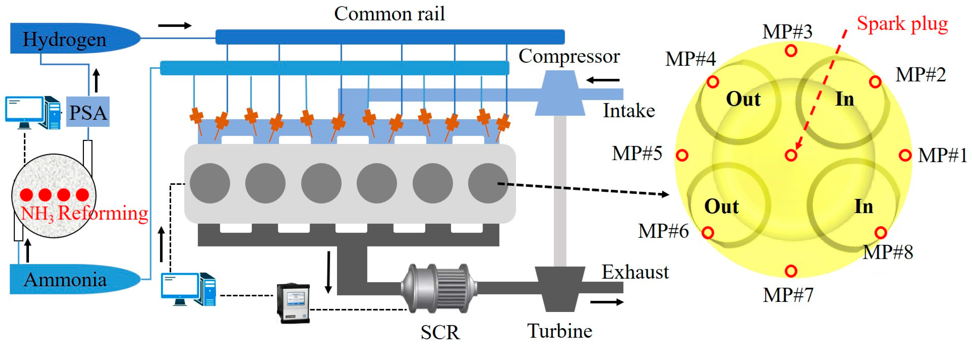
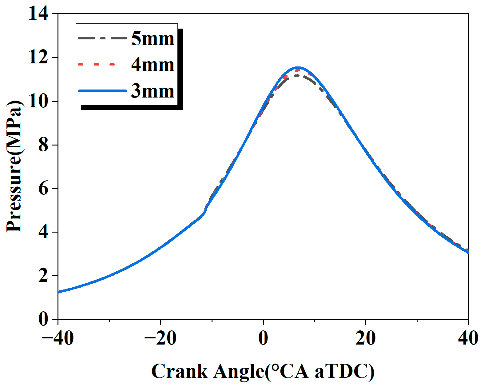
Figure 1 illustrates the layout of the dual-fuel combustion system and the positions of monitoring points. The Caterpillar 3401 heavy-duty engine is selected as the research platform for the ammonia–hydrogen dual-fuel system, with its detailed parameters presented in Table 1. A 3D numerical model was constructed using the computational fluid dynamics (CFD) software CONVERGE 3.0, which excels in dynamic mesh handling and supports adaptive mesh refinement (AMR) to shorten computational time. The model includes components such as the cylinder and intake/exhaust ports and simulates the engine’s working process as realistically as possible to better capture the influence of intake and exhaust on in-cylinder mixing and combustion. As shown in Figure 2, for grid independence verification, three basic grid sizes (5 mm, 4 mm, 3 mm) were proposed, and the same refinement scheme was applied to different basic grids. There are no significant differences in the results under the 4 mm and 3 mm grids, while the cylinder pressure curve decreases excessively under the 5 mm grid. To balance computational accuracy and efficiency, the 4 mm basic grid size was finally selected. The refinement scheme is as follows: first-level fixed refinement for the entire model, third-level fixed refinement at the intake and exhaust chambers, fourth-level fixed refinement at the spark plug, and third-level adaptive refinement based on temperature and velocity in the cylinder.

2.2. Model Validation

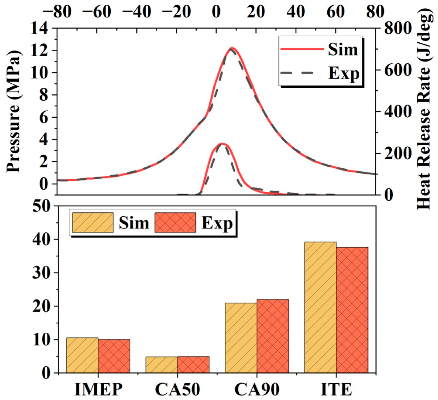
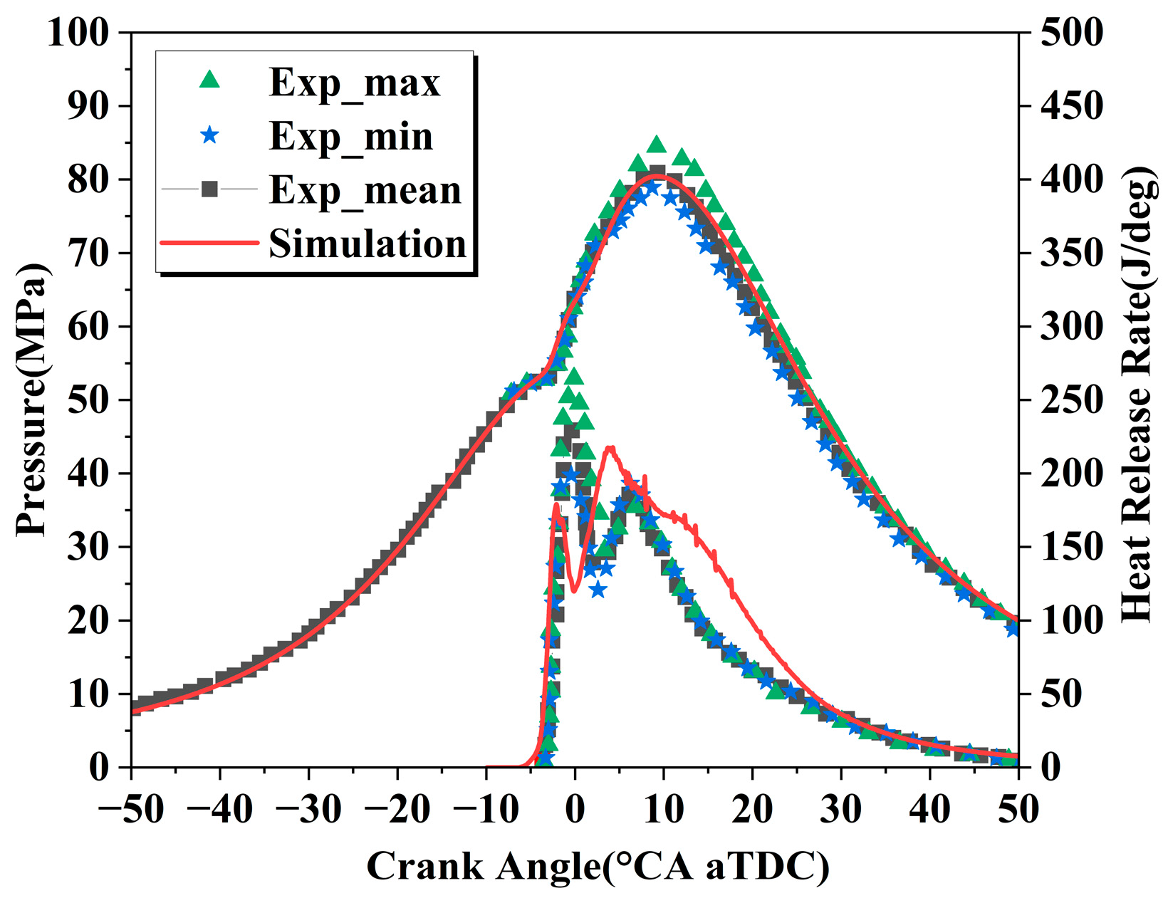
Most existing ammonia–hydrogen experiments focus on small-bore engines, with limited research on heavy-duty counterparts. Thus, this study validates the accuracy of the ammonia–hydrogen premixed engine model through two steps. First, based on the ammonia–diesel dual-fuel experiment by Yousefi et al. [32], the 3D engine model was calibrated at the operating condition of 50% load and 40% ammonia energy ratio. Boundary conditions and initial conditions have a significant impact on the accuracy of CFD simulations. Therefore, the initial conditions of the CFD simulation are consistent with the experimental parameters, where the engine speed is set to the commonly used 910 rpm, and the remaining parameters are listed in Table 2. The ammonia–diesel dual-fuel combustion mechanism adopted in this study is proposed by Zhou et al. [33], which includes 65 species and 344 reactions. Table 3 summarizes the computational models employed in the 3D simulation process in this research. As shown in Figure 3, the cylinder pressure and HRR obtained through simulation are in good agreement with the experimental data, indicating that the selected model and parameter settings are reliable for predicting the combustion processes.
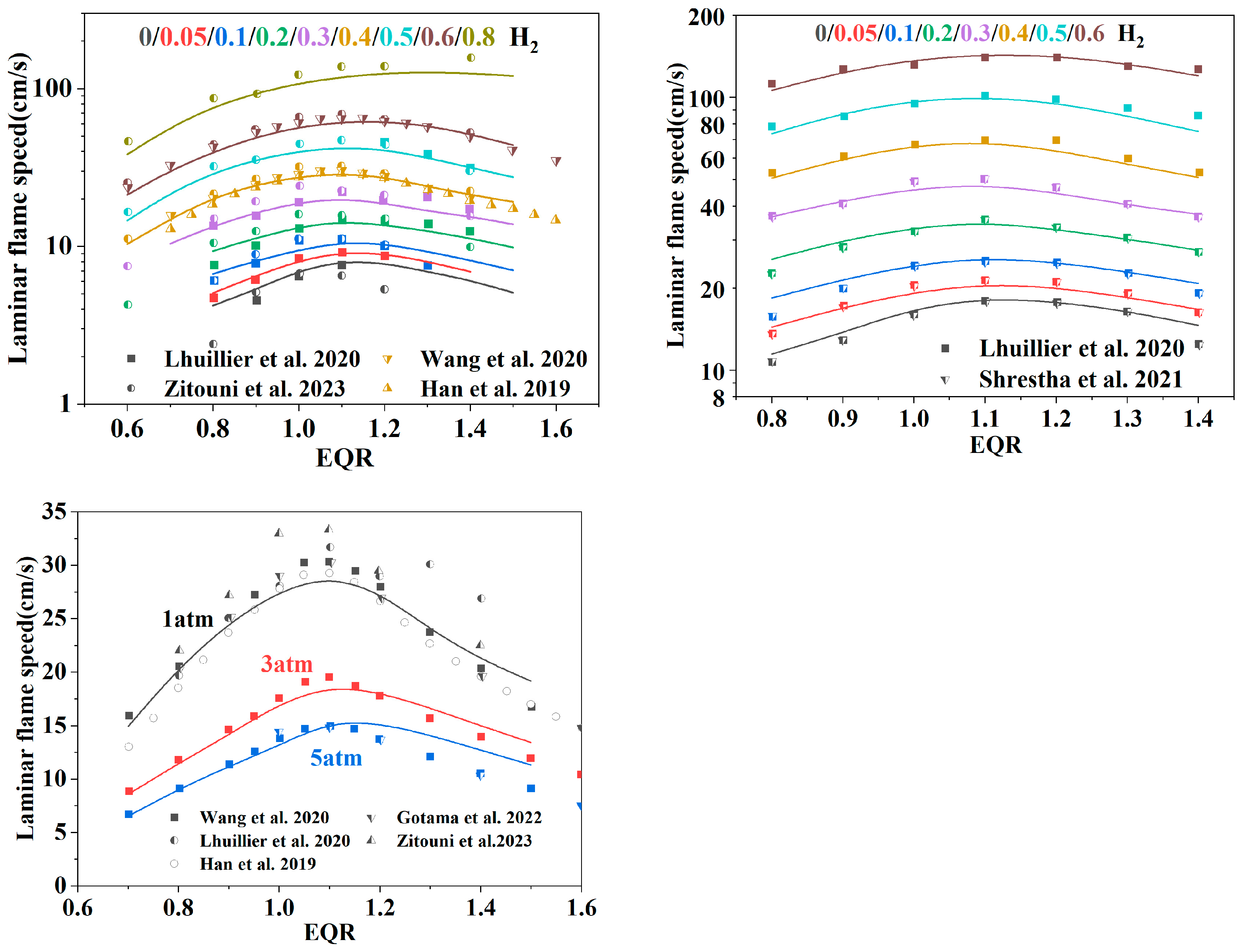
Since the existing ammonia–hydrogen experimental data cannot meet the cylinder bore-matching requirements for heavy-duty engines, this study adopts a two-step model validation strategy of “ammonia–diesel dual-fuel experiment calibration + ammonia–hydrogen combustion mechanism verification”. The ammonia–hydrogen blended combustion mechanism proposed by Stagni et al. [34] is selected, which includes 31 species and 203 reactions. A perfectly stirred reactor model with excellent chemical kinetic performance is used to simulate the ignition and flame propagation processes, which are verified against experimental data [14,35,36,37,38,39]. As shown in Figure 4, this mechanism exhibits good accuracy in terms of basic thermophysical properties. Similarly, Stagni conducted a sensitivity analysis for different operating conditions. Based on the relevant data, the engine operating conditions of this study fall within the reasonable scope of application of this mechanism.
Meanwhile, Zhu et al. [40] also conducted the verification on this mechanism based on ammonia–hydrogen engine experiments. The engine specifications are listed in Table 4, and the verification results are shown in Figure 5, which demonstrates the applicability of this mechanism in ammonia–hydrogen dual-fuel engines. Therefore, based on accurate physical processes, boundary conditions, and a reliable mechanism, this study investigates the premixed spark ignition of the ammonia–hydrogen dual-fuel engine for the heavy-duty engine. The ignition process is modeled by directly providing a two-stage (L-shaped, 140 mJ) energy distribution. Eight monitoring points are set in the cylinder to monitor pressure, with their positions shown in Figure 1.

2.3. Numerical Methodology and Operating Conditions

To accurately identify knock risks, this study processes cylinder pressure signals using the time–frequency domain conversion method: perform the Fourier transform on the pressure curve of monitoring points, convert the time-domain signal to a frequency-domain signal, retain classical knock frequency-domain characteristic signals through 5–20 kHz band-pass filtering, and then obtain the pressure oscillation curve via inverse Fourier transform. The frequency range is calculated by the wave equation [41]. The resonance frequency under different detonation modes is shown in Table 5. The wave equation is defined as follows:
f α , β = C ρ α , β π B
Here, f α , β is resonance frequency; C is the local sound velocity inside the combustion chamber, ρ α , β is resonance mode factor; α and β are the number of radial pressure nodes and circumferential pressure nodes; and B is the cylinder diameter.
Based on the above research gaps, this study focuses on the following work: verify the model’s prediction accuracy of cylinder pressure, HRR and NOX emissions under different HER, SI timing, and EQR conditions, and optimize the knock suppression; reveal the combined mechanism of mixture distribution and flame propagation in large-bore combustion chambers; and achieve the synergistic goal of high ITE and low emissions through optimal parameter combination, providing a theoretical basis and technical support for the engineering application of large-bore ammonia–hydrogen dual-fuel engines. The simulation conditions are shown in Table 6, and HER is defined as follows:
H E R = m H 2 × L H V H 2 m H 2 × L H V H 2 + m N H 3 × L H V N H 3 × 100 %
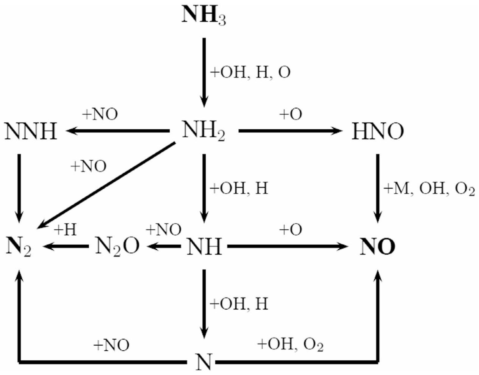
Here, m H 2 represents the mass of hydrogen and m N H 3 represents the mass of ammonia. L H V H 2 denotes the lower heating value of hydrogen and L H V N H 3 represents the lower heating value of ammonia. In order to better understand the influence of different parameters on the generation of NOX, this study introduced a reaction pathway diagram of NH3, as shown in Figure 6. The dehydrogenation reactions of ammonia are as follows:
NH3 + OH → NH2 + H2O
NH3 + H → NH2 + H2
The reactions of ammonia to generate NO are as follows:
NH + O2 → NO + OH
NH + O → NO + H
HNO → NO + H
HNO + H → NO + H2
HNO + OH → NO + H2O
HNO + O → NO + OH

3. Results and Discussion

3.1. Effect of Ignition Timing on Combustion and Emissions

This section focuses on the typical operating condition of an ammonia–hydrogen heavy-duty dual-fuel engine with a HER of 4% and an Φ = 1.0, systematically investigates the regulation laws of SI timing on its combustion process and emission characteristics, and simultaneously conducts the optimization of IMEP and knock risk analysis, providing a basis for the parameter optimization of the engine combustion system.
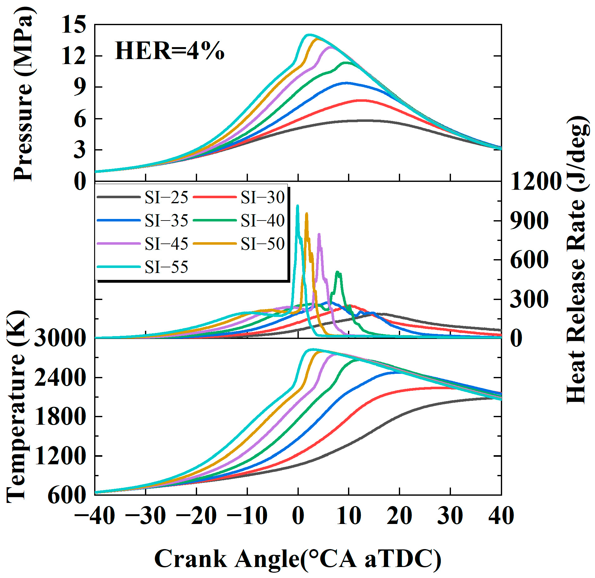
As shown in Figure 7, advancing the SI timing exerts a notable regulatory impact on the dynamic changes in cylinder pressure and HRR: as the ignition timing moves from the retarded phase to the advanced phase, both the peak cylinder pressure and peak HRR exhibit a consistent trend of increasing and shifting forward. When the ignition timing is advanced to −40 °CA aTDC, the HRR curve exhibits an obvious sudden increase characteristic, and the rate of increase in the average cylinder temperature accelerates simultaneously. This phenomenon stems from the fact that advanced ignition extends the effective combustion duration of the cylinder combustible mixture, prompting the ammonia–hydrogen blended fuel to enter the intense combustion stage earlier in the late compression stroke. The released chemical energy is more concentratedly converted into a cylinder pressure rise, ultimately manifesting as a rapid rise in the cylinder pressure curve. When the ignition timing is further advanced, the sudden increase effect of the peak HRR is more pronounced, the peak value further increases, and the advancement amplitude of the peak cylinder pressure increases. This fully proves that under the operating condition of HER = 4% and Φ = 1.0, advanced ignition promotes the improvement of combustion intensity and exerts a positive regulatory effect on the cylinder combustion process.
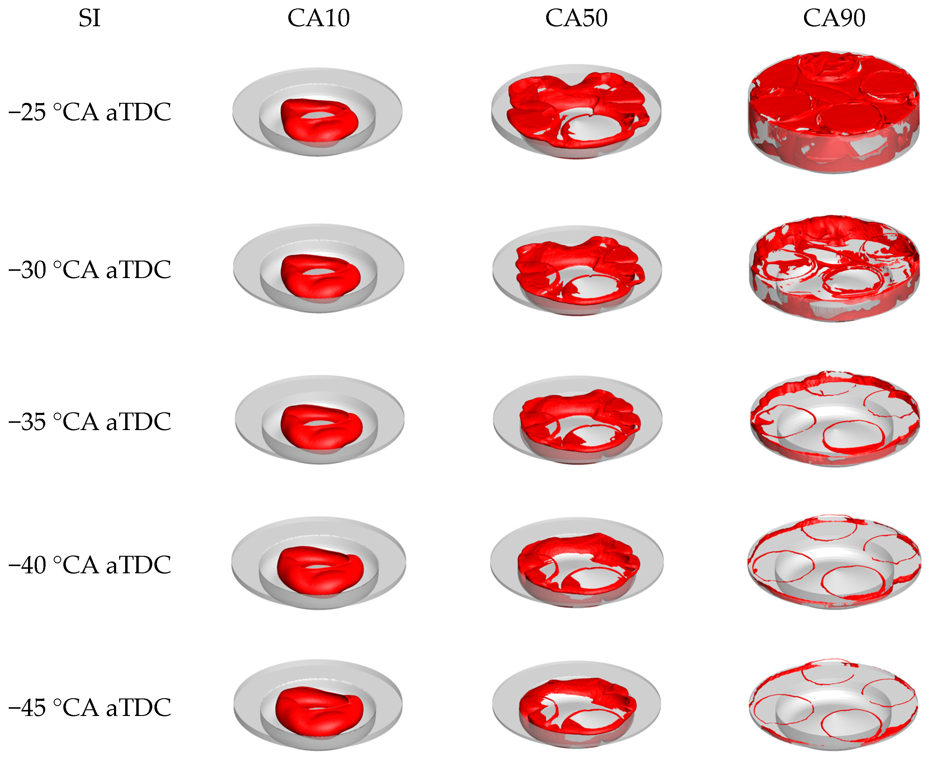
Figure 8 illustrates the flame front using a 1800 K temperature contour, systematically compares the flame development trends at characteristic combustion phases (CA10, CA50 CA90) under different ignition timing conditions, and reveals the intrinsic correlation between ignition timing, flame morphology evolution, and combustion rate. In terms of the temporal evolution of flame front morphology, CA10 shows high consistency at all ignition timing conditions: the flame fronts all exhibit the characteristic of being locally concentrated with a limited range and the morphological differences are negligible. This phenomenon indicates that in the initial stage of spark plug ignition, cylinder combustion proceeds in a laminar flame diffusion-dominated mode. At this time, the oxidation reaction of the ammonia–hydrogen blended fuel is still in the free radical accumulation stage, with low active free radical concentration and slow flame propagation speed. However, the flame front shapes at CA50 and CA90 under different ignition timings are less consistent and the regulatory effect of ignition timing on flame front morphology becomes significantly apparent. Overall, there is a trend that the more retarded the ignition timing, the larger the flame area, reflecting the core issue that retarded ignition timing leads to a reduced combustion rate and prolonged combustion duration. Taking the ignition timings of −25 °CA aTDC and −40 °CA aTDC as examples, the condition at −25 °CA aTDC has a lower combustion intensity. Due to the retarded ignition phase, the in-cylinder temperature and pressure in the late compression stroke are lower, resulting in lower combustion intensity and a slower oxidation reaction rate of ammonia–hydrogen fuel. As a result, the flame front has diffused to the outer region of the piston bowl at CA50, with a significantly increased flame coverage area; by CA90, the flame further spreads to the entire cylinder wall and bottom regions of the intake and exhaust valves, indicating that the combustion process is still ongoing with incomplete full heat release. In the −40 °CA aTDC condition, benefiting from the rapidly accumulated free radicals caused by the advanced ignition phase, the flame front at CA50 is basically located in the piston bowl and its upper region without diffusing outward. At CA90, only partial flames exist in the cylinder liner and valve bottom regions, which characterizes rapid and efficient combustion, and this is relatively consistent with the conclusions obtained in Figure 7.
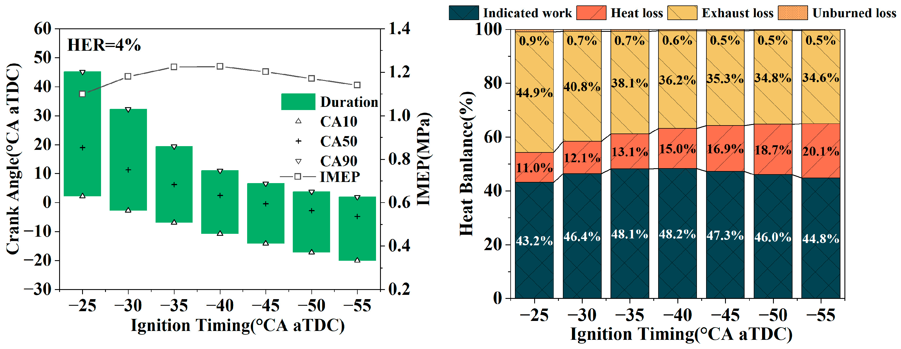
To clarify the correlation between the spark ignition timing and the engine performance, this study investigated the maximum brake torque (MBT) with the maximum IMEP by varying the ignition timing, and we simultaneously analyzed the evolution characteristics of combustion duration and CA50, with the results being shown in Figure 9. In terms of combustion characteristics, with the advancement of ignition timing, the combustion duration gradually shortens and the overall combustion phase advances. The IMEP reaches the MBT under the ignition timing of −40 °CA aTDC. At this time, the combustion duration is approximately 20 °CA and the CA50 is 2.5 °CA aTDC. Combined with the thermal balance analysis results, the proportion of indicated work under this operating condition reaches 48.2%, which is the maximum among all tested operating conditions. However, the heat transfer loss shows a monotonically increasing trend with the advancement of the ignition timing. The core mechanism of this phenomenon is that advanced ignition enhances the in-cylinder combustion intensity, increasing the cylinder peak temperature. The temperature difference between the wall temperature of components such as the cylinder wall, piston top, and cylinder head and the cylinder gas temperature expands, leading to increased heat transfer through the walls. In contrast, the unburned loss gradually decreases with the advancement of the ignition timing, because premixed combustion becomes more complete with the intensification of combustion.
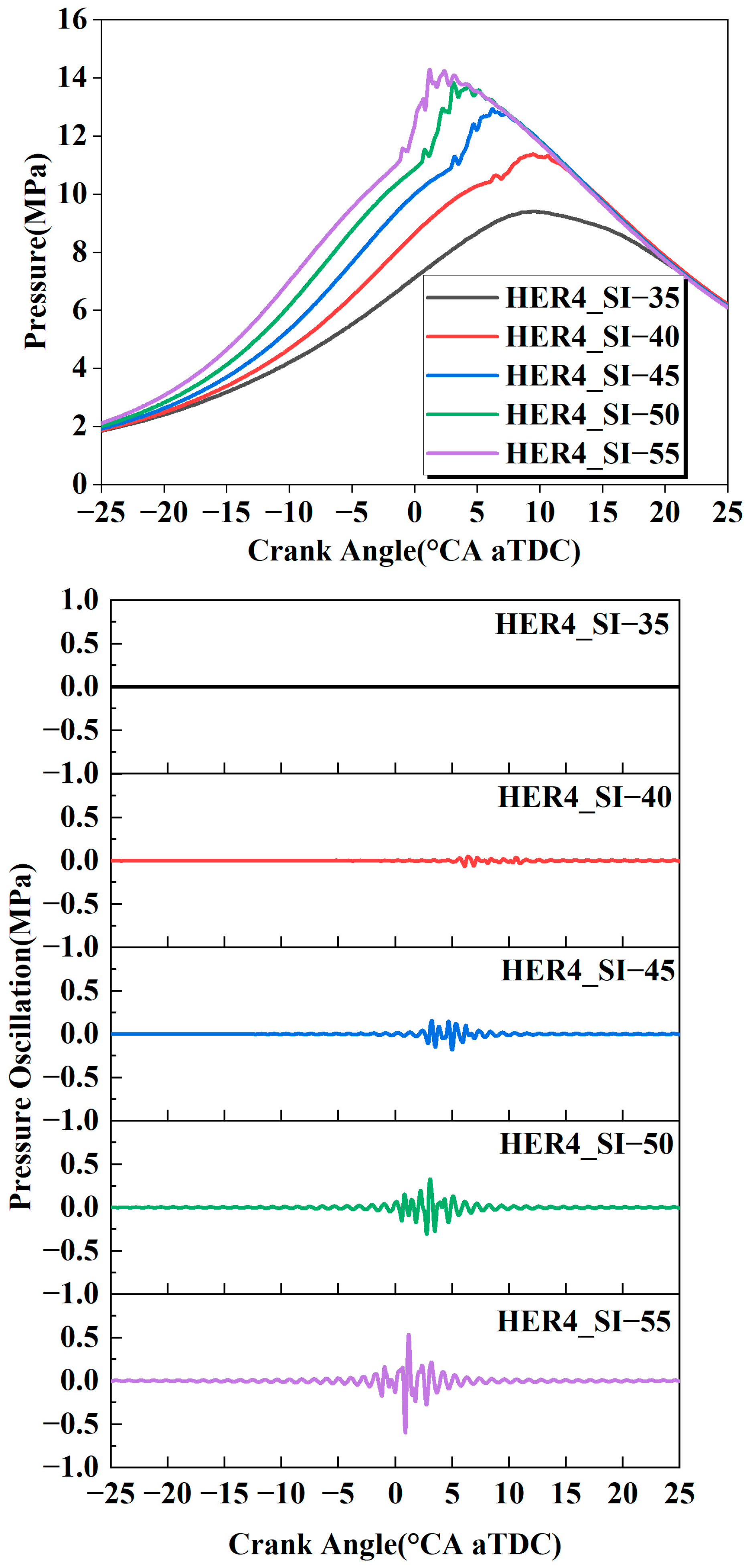
Figure 10 shows the cylinder pressure at monitoring points and the pressure oscillation curve under different spark ignition timings at 4% HER and 1.0 EQR. Based on the relevant empirical parameters for this type of heavy-duty engine, the initial knock can be considered to have occurred when the peak pressure oscillation exceeds 0.15 MPa. In terms of the knock evolution law, the advancement of ignition timing shows a significant positive correlation with the pressure oscillation intensity: obvious oscillation characteristics begin to appear under the ignition timing of −40 °CA aTDC; as the ignition timing advances, pressure oscillations gradually increase and advance, and this trend is consistent with the position of the combustion phases. Consistent with the research findings of Guo et al. [42], appropriate ignition timing can significantly improve engine performance, but attention should also be paid to the impact of the ignition timing on detonation. Considering the balance requirements of IMEP, ITE, and knock risk, taking low pressure oscillation as the safety boundary while ensuring high IMEP and ITE, the −37.5 °CA aTDC operating condition is therefore considered for selection.
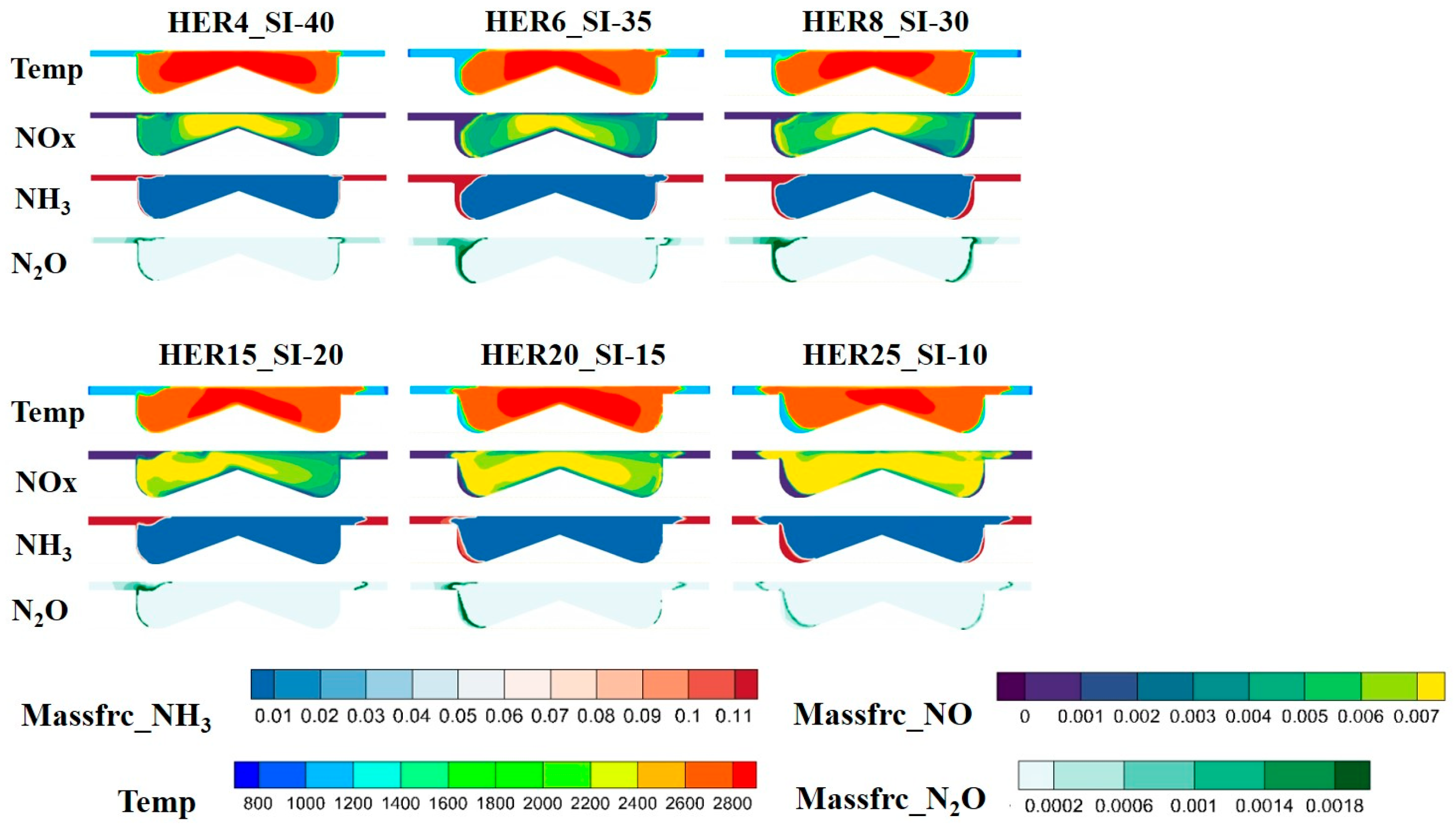
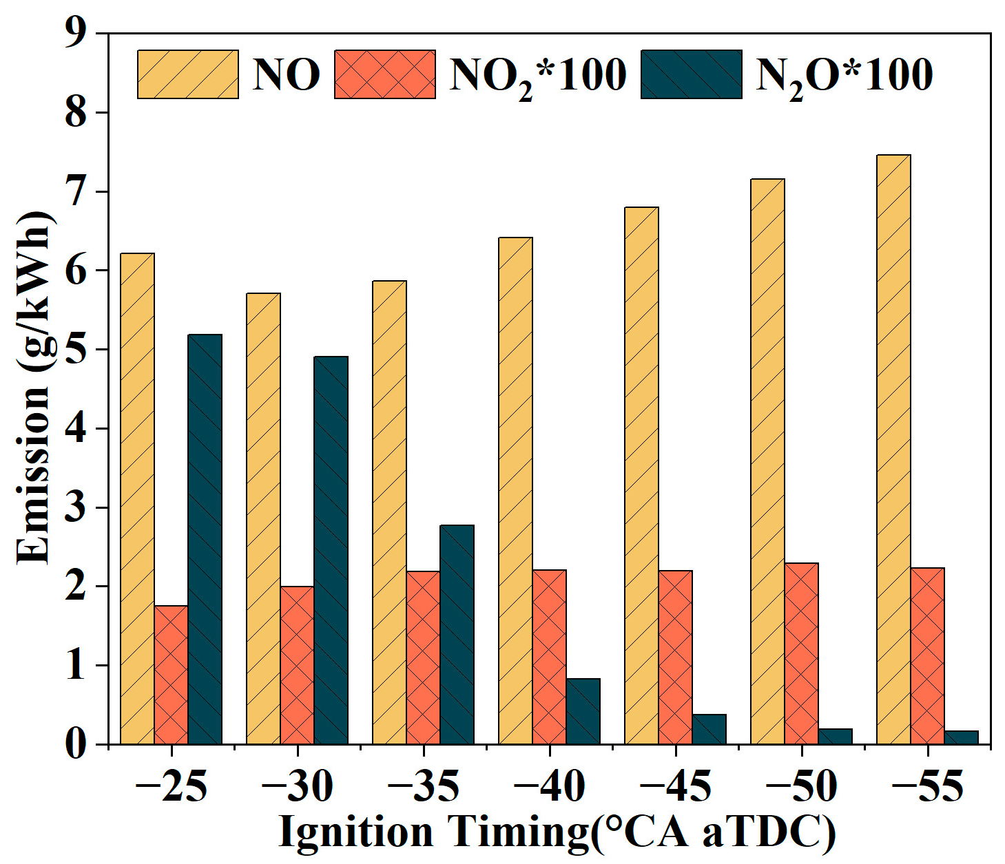
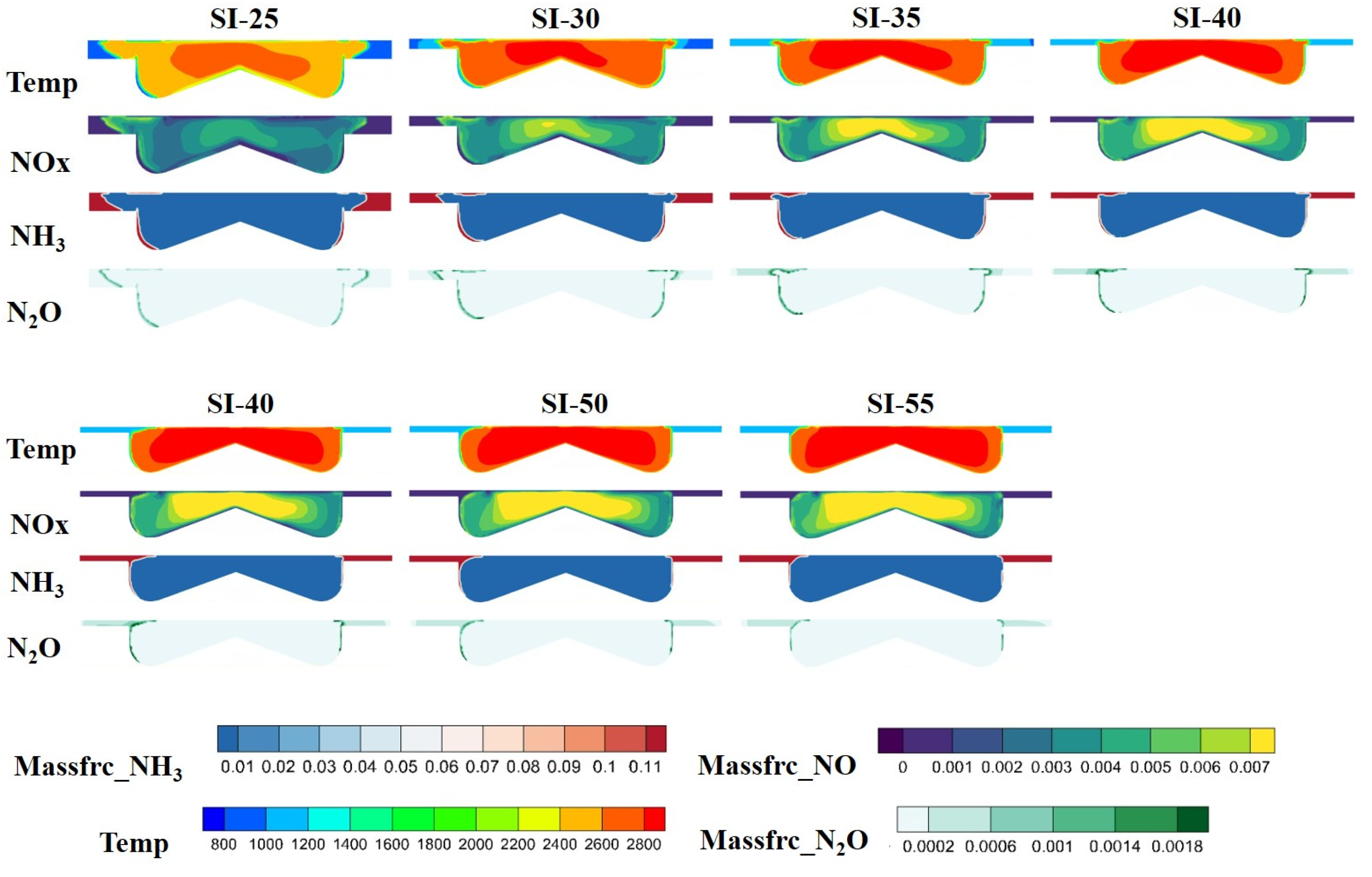
Figure 11 compares the emissions of three types of nitrogen oxides under different ignition timings. As the ignition timing advances, the NO and NO2 emissions mostly show an increasing trend, while the N2O emission exhibits a decreasing trend. This is because as the ignition timing advances, the cylinder temperature rises, and the Zeldovich model for thermal NO formation is highly sensitive to temperature. Specifically, the two main reactions for thermal NO generation are accelerated: N2 + O → N + NO and O2 + N → O + NO. Consequently, the NO emission amount increases significantly with advanced ignition timing, which is consistent with the previous research findings [43]. However, the NO emission amount under the −25 °CA aTDC condition is higher than that under −30 °CA aTDC. This is because the combustion duration under−25 °CA aTDC is excessively long, resulting in an unsatisfactory combustion efficiency. The prolonged combustion duration causes the NO generated in the early stage to lack a sufficient reduction reaction time during the low-temperature phase of the expansion stroke, leading to the accumulation and generation of more NO. As shown in Figure 6, the main formula is NH2 + NO → N2 + H2O. N2O is mainly generated through low-temperature reaction pathways and tends to decompose in high-temperature environments after formation. The generation reactions are NH + NO → N2O + H and HNO + NO → N2O + OH, and the decomposition reactions are N2O + O → N2O + H, N2O + H → N2 + OH and N2O → N2 + O. On the one hand, advanced ignition reduces the duration of cylinder low-temperature zones, inhibiting N2O formation; on the other hand, it expands the coverage of cylinder high-temperature zones, accelerating the decomposition of generated N2O. Therefore, its emission amount decreases. The reduction rates of the minimum values relative to the maximum values for each pollutant are as follows: NO is 23.45%, NO2 is 23.68%, and N2O is 96.85%. Figure 12 shows the slice contours of temperature, NOX, NH3, and N2O at CA50. It can be seen from the figure that as ignition timing advances, the high-temperature region at CA50 expands accordingly, and the high-concentration zone of NOX exhibits a highly overlapping characteristic with the high-temperature region: the core formation zone of thermal NO completely covers the high-temperature region, and the concentration gradient is positively correlated with the temperature gradient. The distribution area of NH3 is mainly in low-temperature unburned zones. As the ignition timing advances, the core combustion zone expands, the area of low-temperature unburned zones shrinks, and the distribution range of unburned NH3 shrinks accordingly, which mutually corroborates the previous conclusion of reduced unburned loss. The high-concentration zone of N2O is concentrated at the edge of the high-temperature region, highly overlapping with the flame front boundary. This characteristic stems from the formation and decomposition characteristics of N2O: the flame front edge is in the transition zone from high to low temperature, which satisfies the temperature requirement for N2O formation while avoiding rapid decomposition caused by high temperatures. As the ignition timing advances, the flame front boundary rapidly propagates toward the cylinder wall, the area of the high-temperature transition zone shrinks, and the formation space of N2O is compressed, ultimately leading to a decrease in its emission amount.

3.2. Effect of Hydrogen Energy Ratio on Combustion and Emissions

This section focuses on the effect of the hydrogen energy ratio on combustion and emissions in the heavy-duty ammonia–hydrogen premixed dual-fuel engine, in which six HERs under the operating condition of Φ = 1.0 is set, and the MBT points under each operating condition through ignition timing optimization and knock analysis are simultaneously conducted, providing a theoretical basis for combustion system optimization.
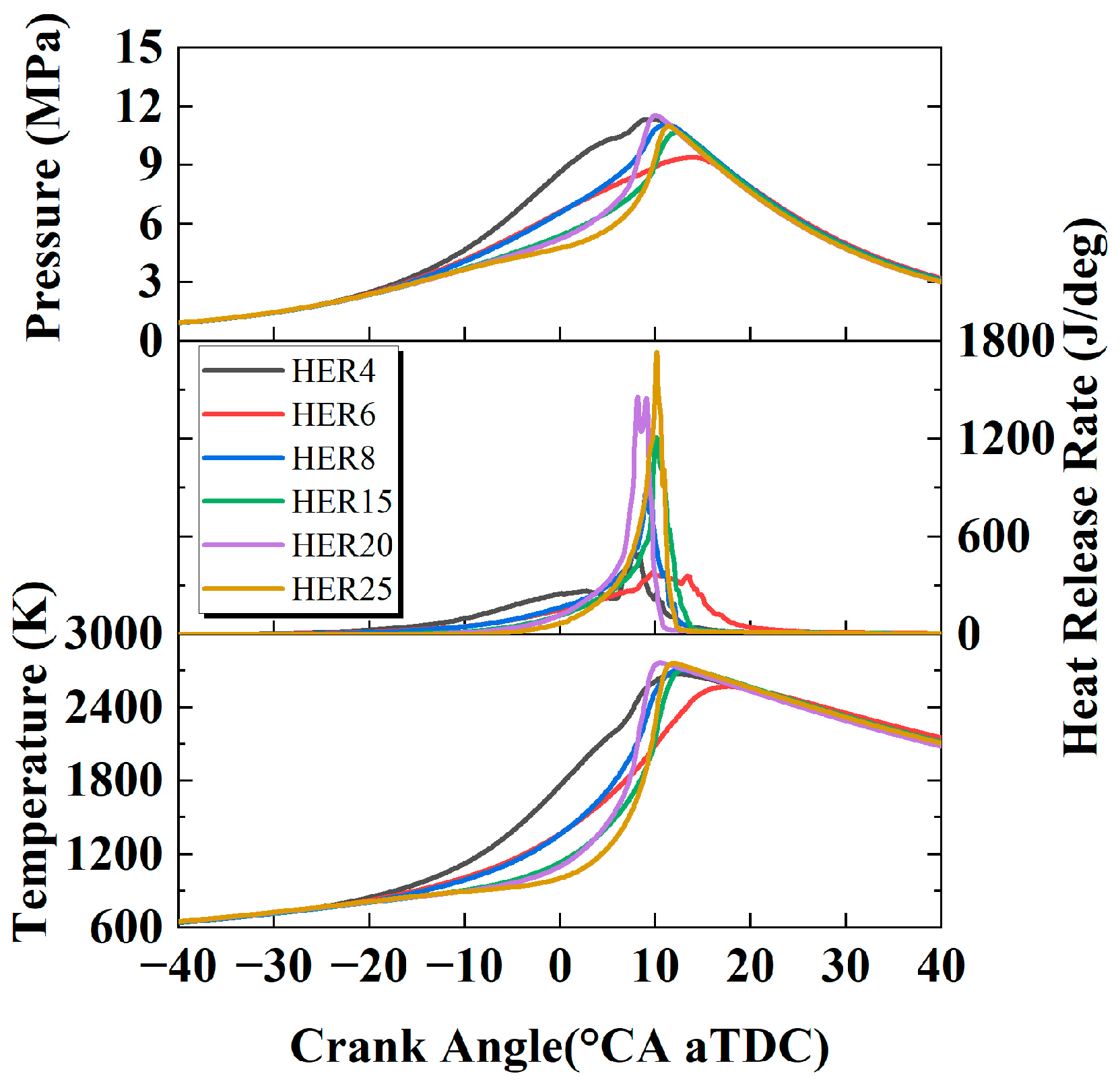
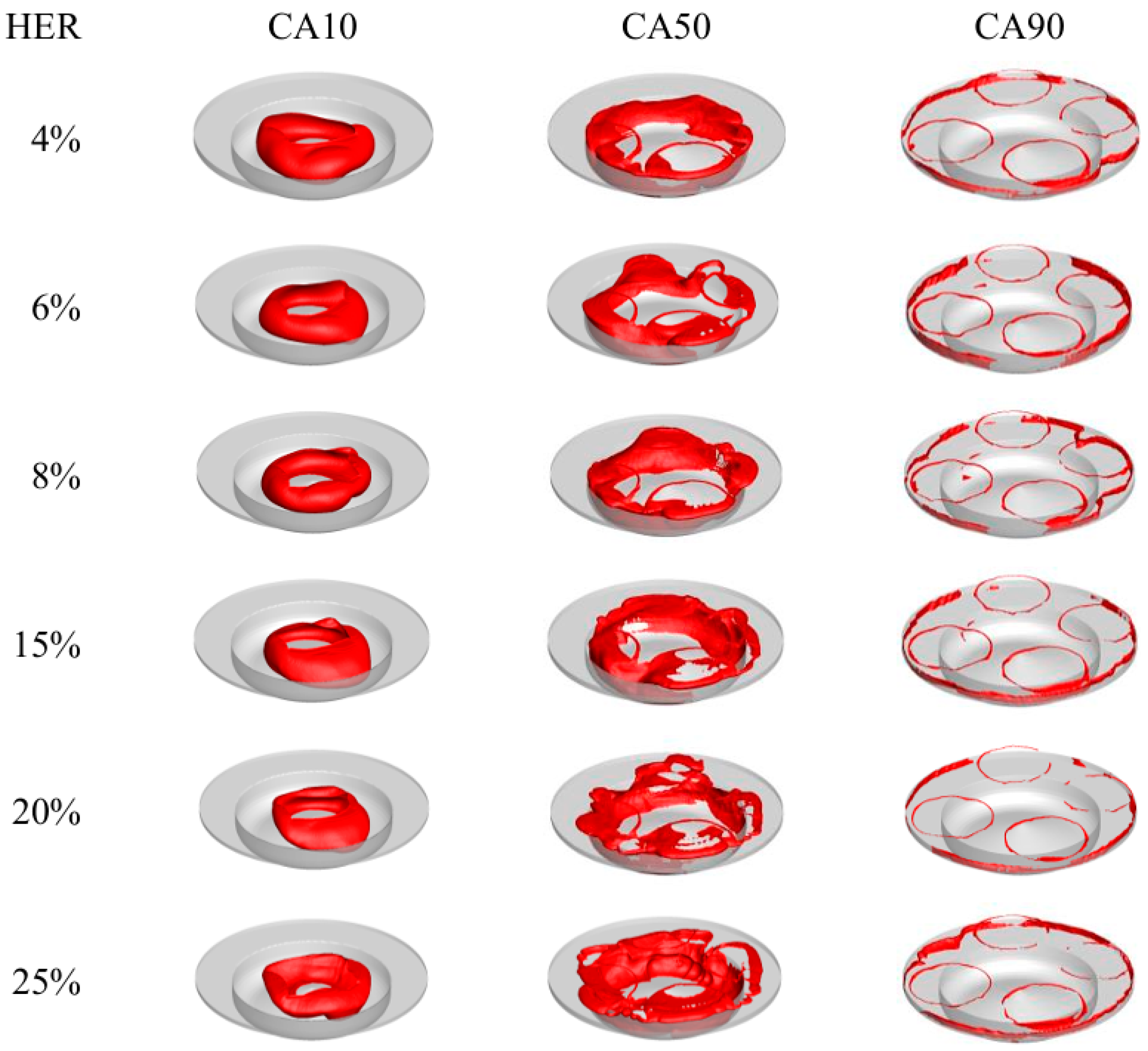
Figure 13 compares the cylinder pressure, HRR, and cylinder temperature under different HERs. As observed from the figure, as HER increases from 4% to 25%, the rise timing of cylinder pressure is delayed due to retarded ignition timing, with the timing of the rapid rise in mean temperature also being delayed. However, due to the flame speed improvement brought by high HER, the pressure rise rate, HRR, and cylinder temperature basically increase with the increase in HER. Although the ignition timing varies for each HER, the peak cylinder pressure and peak HRR are all concentrated around 10 °CA aTDC, reflecting the effect of the optimal ignition timing matching: by adjusting the ignition timing, the CA50 of each HER operating condition is placed at the optimal phase of the expansion stroke, maximizing the conversion efficiency of the chemical energy to mechanical work and ultimately achieving the optimal IMEP. Figure 14 systematically compares the flame development trends at characteristic combustion phases under different HER operating conditions and reveals the intrinsic correlation between the HER, flame morphology evolution, and combustion rate. It can be seen from the figure that at CA10, for the HER = 4% operating condition, although the flame propagation speed of ammonia is relatively low, the diffusion combustion zone is larger due to the earliest ignition timing, making the flame area at CA10 significantly larger than those of the HER = 6% and HER = 8% operating conditions; however, as HER increases, the highly reactive chain reactions of hydrogen significantly accelerate the generation of active free radicals, the coupling intensity between the dehydrogenation reaction of ammonia and the reaction of hydrogen increases, and the flame propagation speed surges. Therefore, the flame area of the HER = 15% operating condition at CA10 also exhibits a relatively large value. As the HER increases from 4% to 25%, the flame front at CA50 gradually expands from “confined to the piston bowl and its upper core combustion zone” to the cylinder liner region, and the coverage area continues to increase. Meanwhile, the distortion degree of the flame front morphology is significantly intensified. This is because the local high reaction rate of hydrogen and the slow reaction zone of ammonia under high HER form an inhomogeneous flame front, and the chain reactions of hydrogen and the oxidation reactions of ammonia intertwine spatially, promoting the flame front to spread rapidly and irregularly. At CA90, since all HER operating conditions are for MBT conditions, the effects of the flame front are relatively consistent. The residual flames are only distributed at the in-cylinder low-temperature boundary layer (cylinder liner wall and valve bottom), which is caused by the slow oxidation of the unburned mixture in the low-temperature environment near the wall.
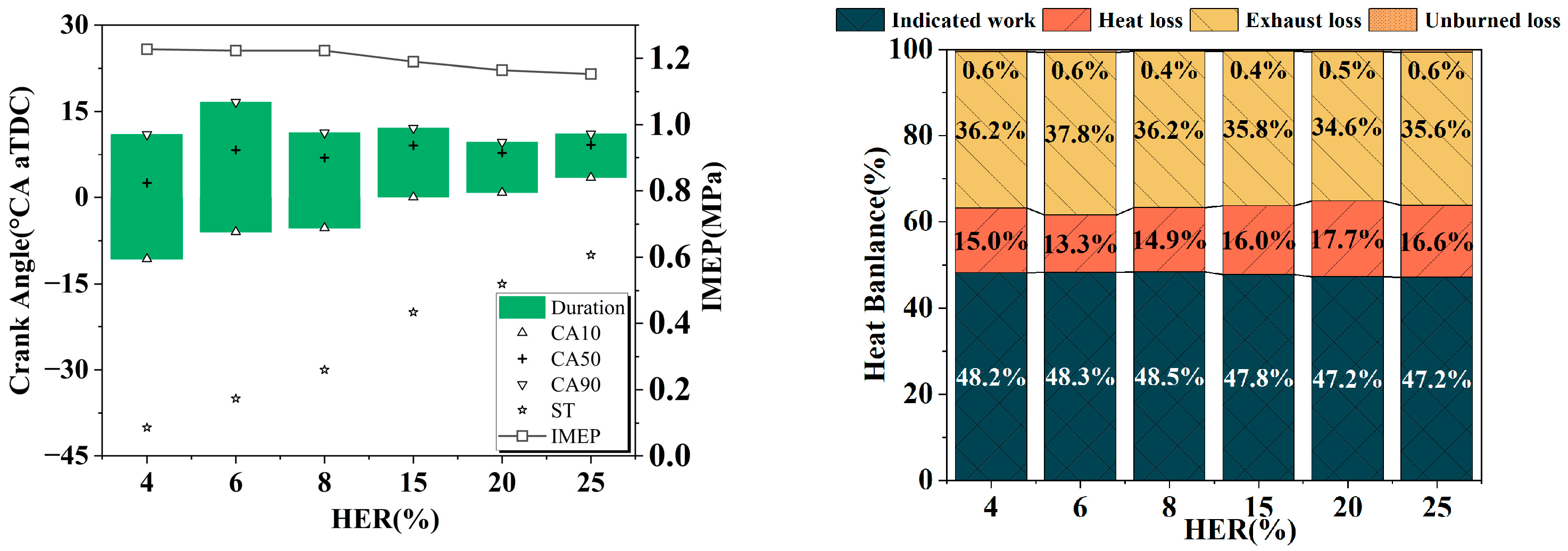
Figure 15 reflects the combustion duration, IMEP, and heat balance under different HER operating conditions. It can be seen that as the HER increases, the combustion duration gradually shortens, which is attributed to the significant enhancement of the flame propagation speed by the increased hydrogen proportion. Except for the 4% HER condition, the optimal CA50 of the other conditions is basically located around 10 °CA aTDC. However, the combustion durations under the 4% HER and 6% HER conditions are obviously basically consistent. The reason may be that due to computational resource constraints in this study, the ignition timing interval is 5 °CA, so there may be few errors for the MBT. The IMEP is distributed around 1.2 MPa, and the IMEP of high HER conditions decreases, which is consistent with the trend of the indicated work. This may be due to local incomplete combustion caused by excessively fast flame speed. In terms of heat transfer loss, although there is no obvious regularity, compared with Figure 9, there is little difference in heat transfer loss under different HER conditions, which indirectly proves that the engine performance is basically consistent under these six HER conditions.
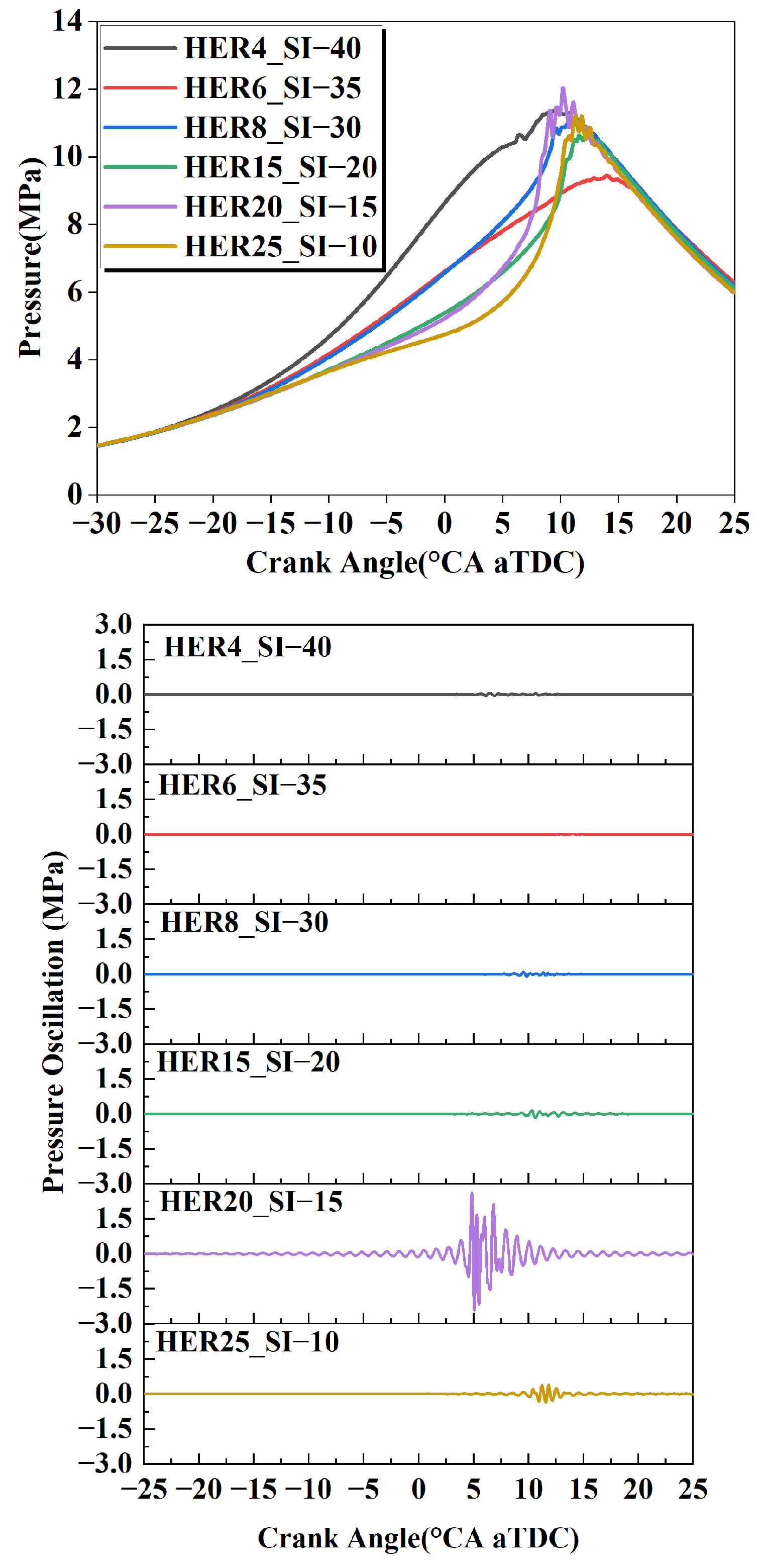
Figure 16 shows the cylinder pressure at monitoring points and pressure oscillation curves under different HER operating conditions. It can be seen that under the ignition timing of MBT at Φ = 1.0, except for the HER = 6% condition where no obvious pressure oscillation is detected, pressure oscillation characteristics are detected in all other HER operating conditions. This indicates potential knock risks in these conditions, which requires retarding the ignition timing to adjust the combustion phase and avoid high-frequency pressure fluctuations. Further analysis of the correlation between the onset time of the pressure oscillation and the CA50 shows that except for the 20% HER condition, the onset time of the pressure oscillation in other operating conditions is highly coincident with CA50. This regularity is consistent with the previous conclusion that excessively advanced CA50 is prone to inducing the knock, verifying that the combustion phase is the core factor for regulating knock risk. In particular, the pressure oscillation amplitude of the 20% HER operating condition is significantly higher than those of other operating conditions, and the oscillation onset time is earlier than CA50. It is speculated that the ignition timing corresponding to the current MBT under this condition is still relatively advanced, and the ignition timing needs to be further retarded. This is to alleviate the severity of the knock by extending combustion duration, reducing the cylinder peak pressure and temperature, and thereby achieving a balance between dynamic performance and knock safety.
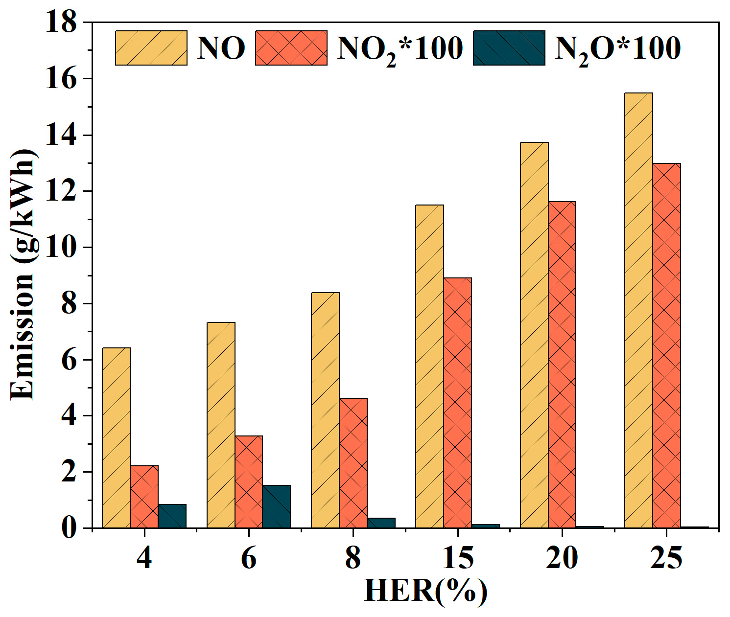
Figure 17 compares the emissions of three types of nitrogen oxides under different HERs. Obviously, as the HER increases, the amounts of NO and NO2 emissions increase. This is because increasing the HER leads to accelerated flame propagation speed, and the cylinder combustion temperature rises sharply in a short time. The Zeldovich mechanism for thermal NO formation is highly temperature-sensitive, causing a significant increase in the NO emission amount. As a secondary oxidation product of NO, the emission trend of NO2 is consistent with that of NO, but the total amount is relatively small. Overall, N2O decreases with the increase in HER, for the same reason as earlier. However, the N2O emission amount is relatively high under the 6% HER condition. This is mainly because the MBT has not been reached due to computational accuracy, requiring further calculations, but it does not affect the overall regularity. The reduction rates of the minimum values relative to the maximum values for each pollutant are as follows: NO is 58.59%, NO2 is 83.01%, and N2O is 97.62%. Figure 18 shows the slice contours of temperature, NOX, NH3, and N2O at CA50. As shown in the figure, the shapes of the temperature regions of 1800 K and above are inconsistent under different HER conditions. Compared with the 4%, 6%, and 8% HER conditions, the temperature regions of the high HER conditions are closer to the cylinder liner region, which is basically consistent with the flame front distribution in Figure 14. As the HER increases from 4% to 25%, the distribution area of NOX gradually spreads from being highly coincidental only with high-temperature regions to lower-temperature regions. This indicates that under high HER conditions, more NOX fuel may be generated, which is related to reactions 5–10. In addition, NH3 is mainly distributed in in-cylinder low-temperature unburned zones, with partial differences depending on the development and distribution of the flame front. The distribution of N2O is consistent with the analysis above: its high-concentration zone is concentrated at the edge of the high-temperature region, which is highly coincidental with the flame front boundary. As the HER increases, the flame front boundary rapidly propagates toward the cylinder wall, the area of the high-temperature transition zone shrinks, and the formation space of N2O is compressed, ultimately leading to a decrease in its emission amount.

3.3. Effect of Equivalence Ratio on Combustion and Emissions

This section focuses on the effect of the equivalence ratio on combustion and emissions in a heavy-duty ammonia–hydrogen premixed dual-fuel engine, in which three EQRs (0.8, 0.9, 1.0) under the HER = 4% operating condition are set. The intake pressure is fine-tuned to vary the EQR while maintaining a consistent fuel mass. Ignition timing optimization and knock analysis are simultaneously conducted for the MBT points under each operating condition, providing a theoretical basis for combustion system optimization.
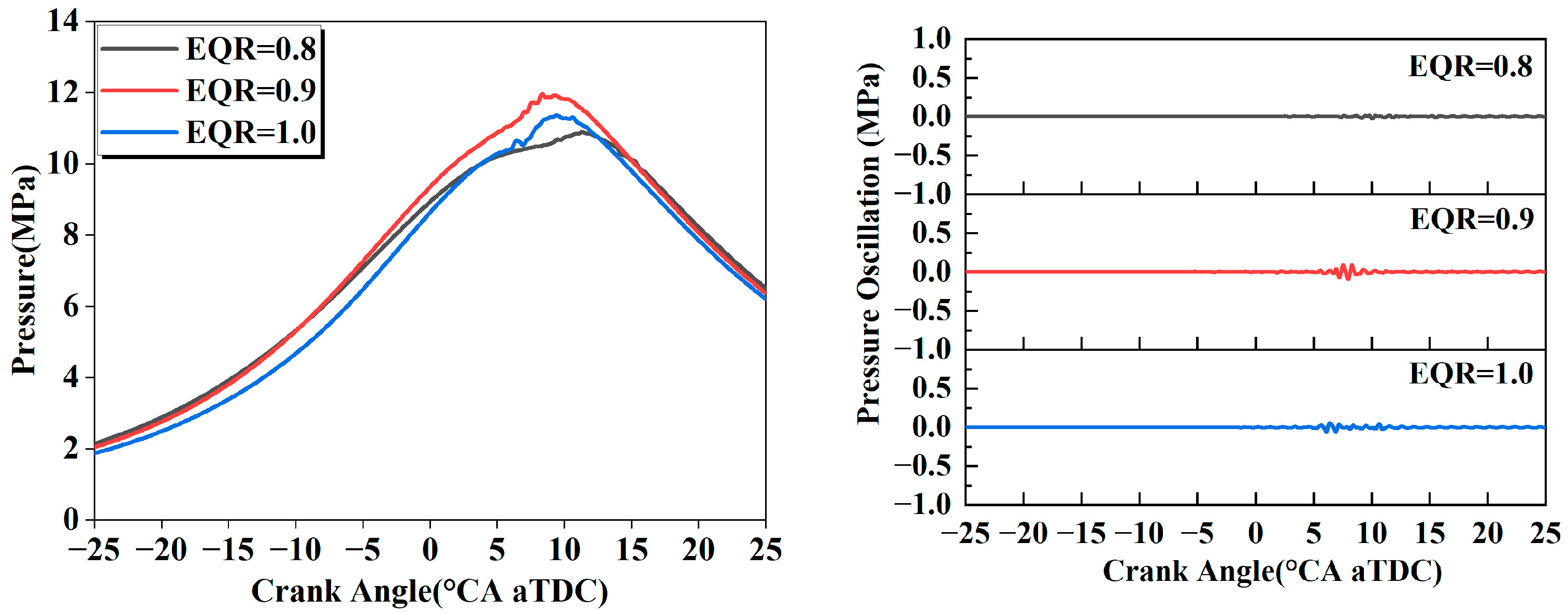
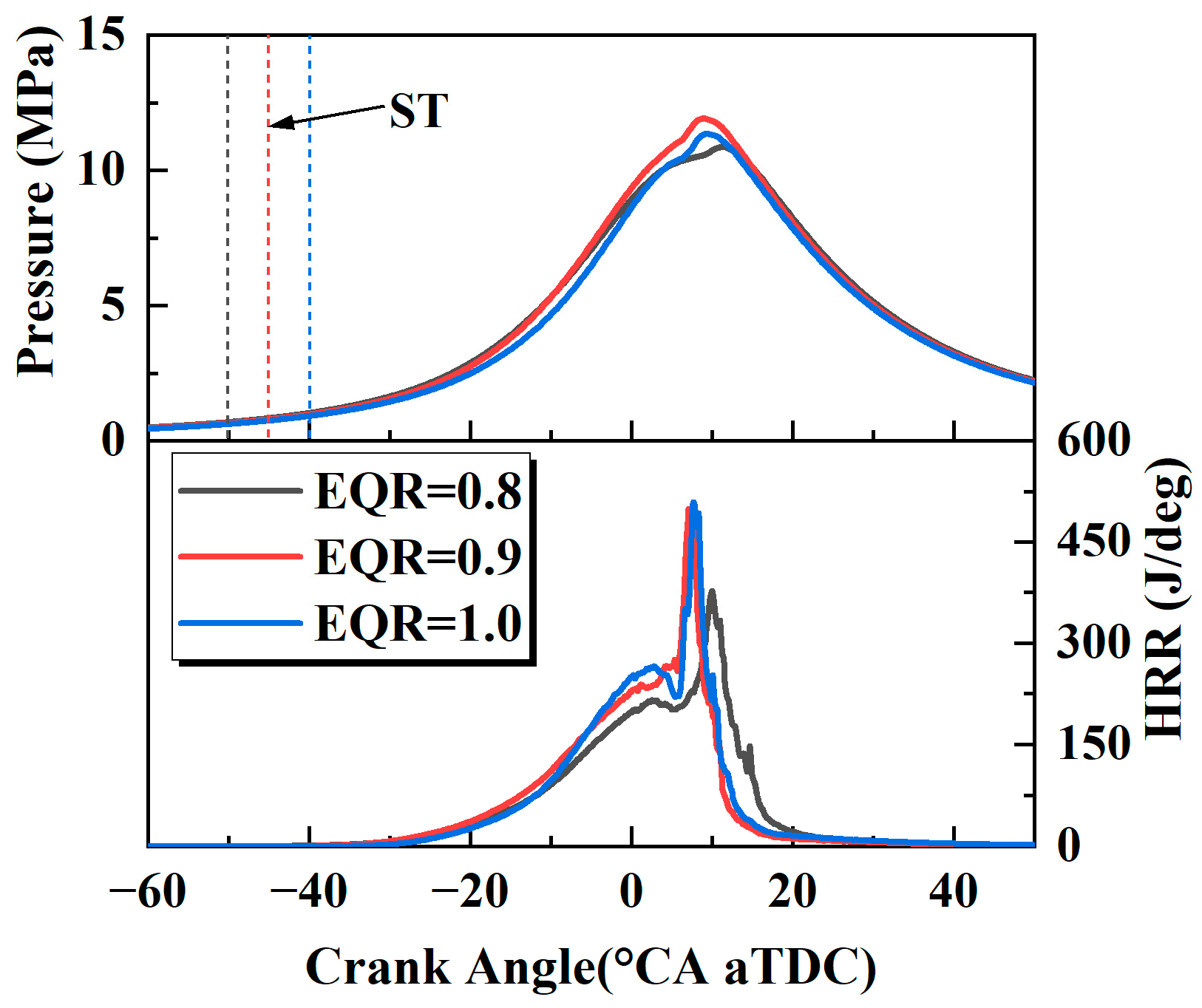
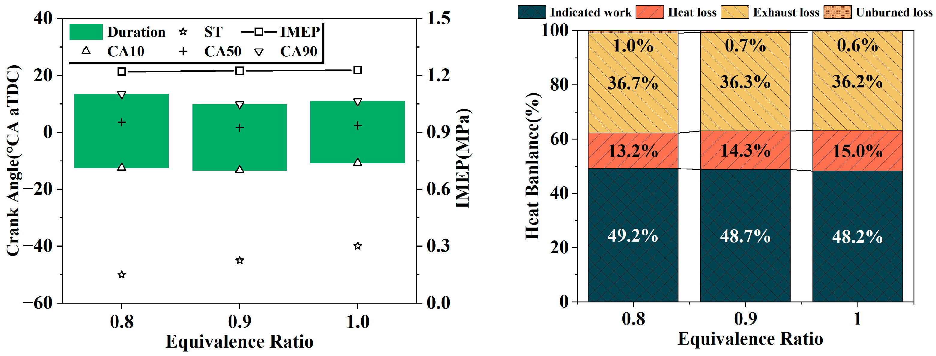
Figure 19 presents the in-cylinder pressure and HRR under different EQRs. It is observed that when the EQR increases from 0.8 to 1.0, the in-cylinder pressure exhibits few changes, and the phase for the pressure peak is largely consistent. Meanwhile, although the ignition timing for higher equivalence ratios is relatively retarded, the peak HRR advances and gradually increases, owing to the enhanced flame speed. The cylinder pressure and HRR curves in Figure 19 reveal the regulatory effect of the equivalence ratio on the combustion process: when the equivalence ratio increases from 0.8 to 1.0, there are no significant changes in the peak cylinder pressure and its phase. Although the ignition timing of the high EQR condition is relatively retarded, its flame propagation speed increases with the rise in equivalence ratio, leading to a gradual increase and forward shift in the peak HRR, which reflects the strengthening effect of the increased equivalence ratio on combustion intensity. The combustion duration, performance, and heat balance data in Figure 20 show that under the same HER, the IMEP under different EQR conditions can be maintained consistently by adapting the ignition timing, reflecting the compensatory regulatory effect of the ignition timing on the combustion phase. The combustion duration shows a monotonically decreasing trend with the increase in EQR. The main reason is that the increase in EQR promotes the coupling of the oxidation reactions of ammonia–hydrogen fuel (synergistic enhancement of hydrogen chain reactions and ammonia dehydrogenation reactions), which improves the flame propagation rate and shortens the time required for complete combustion of the fuel. The heat balance analysis results show that when the EQR increases from 0.8 to 1.0, the proportion of indicated work gradually decreases, and the proportion of heat-transfer loss increases synchronously. On the one hand, the peak combustion temperature increases under high EQR, and the temperature difference between the cylinder gas and components such as the cylinder wall and cylinder head expands, leading to increased conductive heat transfer; on the other hand, when the EQR approaches 1.0, the oxygen content in the cylinder is relatively reduced, and part of the ammonia fuel fails to be fully oxidized due to a lack of oxygen, resulting in a slight decrease in combustion efficiency and ultimately a reduction in the proportion of the indicated work. The pressure oscillation curves in Figure 21 reflect the differences in knock risk under different EQRs: no obvious pressure oscillation is observed under the 0.8 EQR condition, indicating that the current ignition timing is already at the IMBT with no potential knock risk, while slight pressure oscillation characteristics are detected under the 0.9 EQR and 1.0 EQR conditions. It is speculated that their ignition timings are relatively advanced, and it is necessary to adjust the combustion phase by slightly retarding the ignition timing to reduce the in-cylinder local hot spot temperature and pressure rise rate, thereby avoiding knock occurrence.
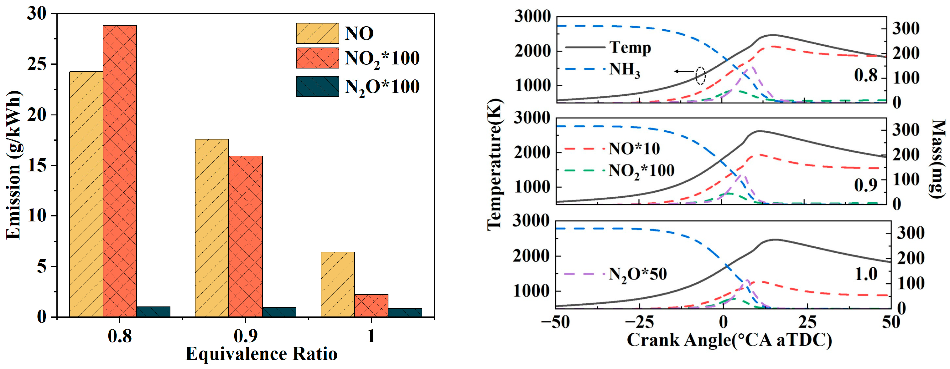
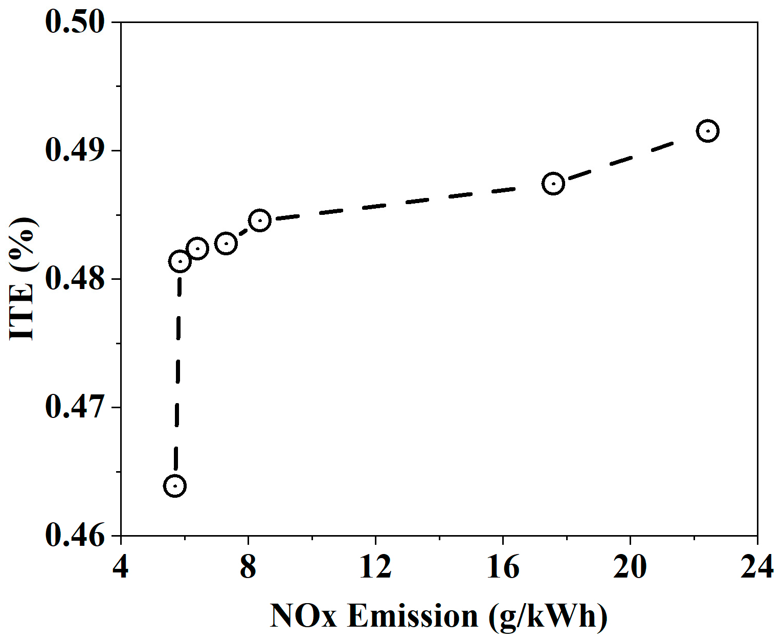
Figure 22 shows the total emissions of three nitrogen oxides under different EQR conditions, the mass change curves of ammonia and nitrogen oxides, and in-cylinder mean temperature variation. It can be seen from the emission amounts and formation curves of the nitrogen oxides that as the equivalence ratio increases, the amounts of NO, NO2, and N2O emissions all decrease. The reduction rates of the minimum values relative to the maximum values for each pollutant are as follows: NO is 73.58%, NO2 is 92.35%, and N2O is 18.24%. Conventionally, thermal NOX increases with the increase in combustion intensity and in-cylinder temperature. However, the variation trend of absolute thermal NO in the cylinder under different EQRs cannot be simply explained by the change in temperature. According to the theory proposed by Yu et al. [43], under lean-burn conditions, the equivalence ratio is low, the combustion efficiency is high, and the content of O radicals is relatively high, which promotes the formation of thermal NOX, resulting in a higher peak NOX content. This theory is consistent with the data obtained in this study. Therefore, although the indicated work is relatively higher under lean-burn conditions, it also leads to more nitrogen oxide emissions. Figure 23 presents the Pareto front derived from the calculated ITE and NOx results under different operating conditions. From the perspective of balancing performance and emissions, an ITE of 48.5% with a NOx emission of 8 g/kWh is relatively optimal.

4. Conclusions

Sustainable and green ammonia utilization is an important research topic in the maritime field. This study focused on a premixed ammonia–hydrogen spark-ignition heavy-duty engine and systematically investigated the regulatory effects of three key operating parameters—spark ignition timing, hydrogen energy ratio, and equivalence ratio—on the engine’s combustion performance, knock characteristics, and NOX and N2O emissions. The research results can be summarized as follows.
  • Under the typical operating condition of HER = 4% and Φ = 1.0, −37.5 °CA aTDC is the optimal ignition timing that balances thermal efficiency (close to the maximum ITE of 48.2%) and knock resistance. This conclusion can directly provide core parameter support for the calibration of the ignition system of heavy-duty ammonia–hydrogen engines. There is no need to excessively pursue advanced ignition to improve power, which avoids increasing the structural load of the cylinder block due to the knock risk and prolongs the service life of the engine.
  • Hydrogen doping is an important method for improving ammonia combustion performance. As the HER increases, the flame propagation speed accelerates and the combustion duration shortens. In terms of emissions, the increase in HER leads to higher NO emissions, while the N2O emissions decrease significantly due to the high-temperature decomposition effect. It is recommended to add a flow guide structure on the top of the combustion chamber to optimize the in-cylinder mixture distribution, weakening the flame distortion caused by the local high reaction rate of hydrogen under high HER conditions.
  • The equivalence ratio affects the trade-off relationship between the combustion intensity and emissions. As EQR increases from 0.8 to 1.0, the flame propagation speed accelerates, and the peak HRR advances and increases. At Φ = 0.8, a maximum ITE of 49.2% is achieved, which ranks among the higher levels when compared with similar studies in the field. The NOX emissions are higher than those under high equivalence ratio operating conditions, due to the enrichment of O radicals, so it is necessary to balance the relationship between combustion performance and emissions.
The prioritized core parameters for heavy-duty ammonia–hydrogen premixed engines are as follows: HER = 4–8%, ignition timing −35–−30 °CA aTDC, Φ = 0.8–1.0, balancing higher ITE with lower NOx and no knock. Future work should include experimental prototyping under these parameters and vehicular ammonia reforming integration. With green ammonia, its well-to-wheel carbon intensity is over 85% lower than traditional diesel engines, supporting transport decarbonization.

Author Contributions

Conceptualization, Q.X.; Methodology, Q.X. and K.H.; Software, K.H.; Validation, X.S.; Formal analysis, Q.X. and K.H.; Investigation, K.H.; Resources, Q.X.; Data curation, K.H.; Writing—original draft, K.H., D.L., J.L. and X.H.; Writing—review & editing, Q.X., K.H., X.S. and D.L.; Visualization, J.L. and X.H.; Supervision, Q.X.; Project administration, Q.X.; Funding acquisition, Q.X. All authors have read and agreed to the published version of the manuscript.

Funding

This research was funded by the National Natural Science Foundation of China, grant numbers T2341001 and 52130605.

Institutional Review Board Statement

Not applicable.

Informed Consent Statement

Not applicable.

Data Availability Statement

The original contributions presented in this study are included in the article. Further inquiries can be directed to the corresponding authors.

Acknowledgments

During the preparation of this manuscript/study, the authors reviewed and edited the output, and they take full responsibility for the content of this publication.

Conflicts of Interest

The authors declare no conflicts of interest.

Abbreviations

The following abbreviations are used in this manuscript:
ICEInternal Combustion Engine
HRRHeat Release Rate
IMEPIndicated Mean Effective Pressure
IVCIntake Valve Close
EVOExhaust Valve Close
aTDCafter Top Dead Center
KH-RTKelvin–Helmholtz Rayleigh–Taylor
CA10 (50\90)Crank Angle at 10 (50\90)% Accumulated Heat Release
MEPCMarine Environment Protection Committee
SISpark Ignition
CRCompression Ratio
Massfrc_Mass Fraction of
NH3Ammonia
ITEIndicated Thermal Efficiency
IVOIntake Valve Open
EVOExhaust Valve Open
CACrank Angle
HEFHydrogen Energy Fraction
N2ONitrous Oxide
NO2Nitrogen Dioxide
NONitric Oxide
EQR (Φ)Equivalence Ratio
MBTMaximum Brake Torque
MPMonitor Point

References

  1. Ni, P.Y.; Wang, X.L.; Li, H. A Review on Regulations, Current Status, Effects and Reduction Strategies of Emissions for Marine Diesel Engines. Fuel 2020, 279, 118477. [Google Scholar] [CrossRef]
  2. Nylund, I.; Ott, M. Development of a Dual Fuel Technology for Slow-Speed Engines. In Proceedings of the CIMAC Congress, Shanghai, China, 19–23 May 2013. [Google Scholar]
  3. Banu, A.; Bicer, Y. Review on COX-Free Hydrogen from Methane Cracking: Catalysts, Solar Energy Integration and Applications. Energy Convers. Manag. X 2021, 12, 100117. [Google Scholar] [CrossRef]
  4. Kobayashi, H.; Hayakawa, A.; Somarathne, K.; Okafor, E.C. Science and Technology of Ammonia Combustion. Proc. Combust. Inst. 2019, 37, 109–133. [Google Scholar] [CrossRef]
  5. Tornatore, C.; Marchitto, L.; Sabia, P.; De Joannon, M. Ammonia as Green Fuel in Internal Combustion Engines: State-of-the-Art and Future Perspectives. Front. Mech. Eng. 2022, 8, 944201. [Google Scholar] [CrossRef]
  6. Cha, J.; Park, Y.; Brigljevi, B.; Lee, B.; Lim, D.; Lee, T.; Jeong, H.; Kim, Y.; Sohn, H.; Mikulčić, H.; et al. An Efficient Process for Sustainable and Scalable Hydrogen Production from Green Ammonia. Renew. Sustain. Energy Rev. 2021, 152, 111562. [Google Scholar] [CrossRef]
  7. Dimitriou, P.; Javaid, R. A Review of Ammonia as a Compression Ignition Engine Fuel. Int. J. Hydrog. Energy 2020, 45, 7098–7118. [Google Scholar] [CrossRef]
  8. Wang, H.; Ji, C.; Shi, C.; Yang, J.; Wang, S.; Ge, Y.; Chang, K.; Meng, H.; Wang, X. Multi-Objective Optimization of a Hydrogen-Fueled Wankel Rotary Engine Based on Machine Learning and Genetic Algorithm. Energy 2023, 263, 125961. [Google Scholar] [CrossRef]
  9. Cornelius, W.; Huellmantel, L.W.; Mitchell, H.R. Ammonia as an Engine Fuel. SAE Trans. 1966, 75, 300–326. [Google Scholar]
  10. Huang, Q.; Liu, J. Preliminary Assessment of the Potential for Rapid Combustion of Pure Ammonia in Engine Cylinders Using the Multiple Spark Ignition Strategy. Int. J. Hydrog. Energy 2024, 55, 375–385. [Google Scholar] [CrossRef]
  11. Lhuillier, C.; Brequigny, P.; Contino, F.; Rousselle, C. Combustion Characteristics of Ammonia in a Modern Spark-Ignition Engine. In Proceedings of the Conference on Sustainable Mobility, Catania, Italy, 14–15 October 2019. [Google Scholar]
  12. Zhu, T.; Yan, X.; Gao, Z.; Qiu, Y.; Zhu, L.; Huang, Z. Combustion and Emission Characteristics of Ammonia-Hydrogen Fueled SI Engine with High Compression Ratio. Int. J. Hydrog. Energy 2024, 62, 579–590. [Google Scholar] [CrossRef]
  13. Liu, J.; Liu, J. Experimental Investigation of the Effect of Ammonia Substitution Ratio on an Ammonia-Diesel Dual-Fuel Engine Performance. J. Clean. Prod. 2024, 434, 140274. [Google Scholar] [CrossRef]
  14. Han, X.; Wang, Z.; Costa, M.; Sun, Z.; He, Y.; Cen, K. Experimental and Kinetic Modeling Study of Laminar Burning Velocities of NH3/Air, NH3/H2/Air, NH3/CO/Air and NH3/CH4/Air Premixed Flames. Combust. Flame 2019, 206, 214–226. [Google Scholar] [CrossRef]
  15. Okafor, E.C. Control of NOx and Other Emissions in Micro Gas Turbine Combustors Fuelled with Mixtures of Methane and Ammonia. Combust. Flame 2020, 211, 406–416. [Google Scholar] [CrossRef]
  16. Guo, X.P.; Li, T.; Huang, S.; Zhou, X.; Chen, R.; Wei, W.; Wu, Z.; Wang, N.; Li, S. Characteristics of Ignition, Combustion and Emission Formation of Premixed Ammonia-Hydrogen Blends by Hydrogen-Fueled Pre-Chamber Turbulent Jets. Energy 2025, 322, 135573. [Google Scholar] [CrossRef]
  17. Lhuillier, C.; Brequigny, P.; Contino, F.; Mounaïm-Rousselle, C. Experimental Study on Ammonia/Hydrogen/Air Combustion in Spark Ignition Engine Conditions. Fuel 2020, 269, 117448. [Google Scholar] [CrossRef]
  18. Koike, M.; Miyagawa, H.; Suzuoki, T.; Ogasawara, K. Ammonia as a Hydrogen Energy Carrier and Its Application to Internal Combustion Engines. In Sustainable Vehicle Technologies; Elsevier: Amsterdam, The Netherlands, 2012; pp. 61–70. [Google Scholar]
  19. Lesmana, H.; Zhang, Z.; Li, X.; Zhu, M.; Xu, W.; Zhang, D. NH3 as a Transport Fuel in Internal Combustion Engines: A Technical Review. J. Energy Resour. Technol. 2019, 141, 70703. [Google Scholar] [CrossRef]
  20. Ryu, K.; Zacharakis-Jutz, G.E.; Kong, S.-C. Performance Enhancement of Ammonia-Fueled Engine by Using Dissociation Catalyst for Hydrogen Generation. Int. J. Hydrog. Energy 2014, 39, 2390–2398. [Google Scholar] [CrossRef]
  21. Comotti, M.; Frigo, S. Hydrogen Generation System for Ammonia—Hydrogen Fuelled Internal Combustion Engines. Int. J. Hydrog. Energy 2015, 40, 10673–10686. [Google Scholar] [CrossRef]
  22. Mounaïm-Rousselle, C.; Bréquigny, P.; Dumand, C.; Houillé, S. Operating Limits for Ammonia Fuel Spark-Ignition Engine. Energies 2021, 14, 4141. [Google Scholar] [CrossRef]
  23. Mørch, C.S.; Bjerre, A.; Gøttrup, M.P.; Sorenson, S.; Schramm, J. Ammonia/Hydrogen Mixtures in an SI-Engine: Engine Performance and Analysis of a Proposed Fuel System. Fuel 2011, 90, 854–864. [Google Scholar] [CrossRef]
  24. Pyrc, M.; Gruca, M.; Tutak, W.; Jamrozik, A. Assessment of the Co-Combustion Process of Ammonia with Hydrogen in a Research VCR Piston Engine. Int. J. Hydrog. Energy 2023, 48, 2821–2834. [Google Scholar] [CrossRef]
  25. Ji, C.; Xin, G.; Wang, S.; Cong, X.; Meng, H.; Chang, K.; Yang, J. Effect of Ammonia Addition on Combustion and Emissions Performance of a Hydrogen Engine at Part Load and Stoichiometric Conditions. Int. J. Hydrog. Energy 2021, 46, 40143–40153. [Google Scholar] [CrossRef]
  26. Dinesh, M.H.; Kumar, G.N. Effects of Compression and Mixing Ratio on NH3/H2 Fueled SI Engine Performance, Combustion Stability and Emission. Energy Convers. Manag. X 2022, 15, 100269. [Google Scholar]
  27. Chen, H.; Ji, C.W.; Wang, S.F.; Xin, G.; Meng, H.; Yang, J.; Ma, H. An Experimental Study of a Strategy to Improve the Combustion Process of a Hydrogen-Blended Ammonia Engine Under Lean and WOT Conditions. Int. J. Hydrog. Energy 2023, 48, 33719–33731. [Google Scholar]
  28. Qiang, Y.; Zhao, S.H.; Su, F.X.; Wang, F.; Yang, J.; Wang, S.; Ji, C. Experimental and Numerical Assessment on Co-Combustion of Hydrogen with Ammonia in Passive Pre-Chamber Engines. Appl. Therm. Eng. 2025, 259, 124919. [Google Scholar] [CrossRef]
  29. Wang, B.; Yang, C.; Chen, Y.X.; Zu, Z.; Lin, H.; Bai, C.; Yin, Y.; Cheng, X. Combustion and Emissions of an Ammonia Heavy-Duty Engine with a Hydrogen-Fueled Active Pre-Chamber Ignition System. Int. J. Hydrog. Energy 2024, 90, 419–430. [Google Scholar] [CrossRef]
  30. Ryu, K.; Zacharakis-Jutz, G.E.; Kong, S.-C. Effects of Gaseous Ammonia Direct Injection on Performance Characteristics of a Spark-Ignition Engine. Appl. Energy 2014, 116, 206–215. [Google Scholar] [CrossRef]
  31. Westlye, F.R.; Ivarsson, A.; Schramm, J. Experimental Investigation of Nitrogen Based Emissions from an Ammonia Fueled SI-Engine. Fuel 2013, 111, 239–247. [Google Scholar] [CrossRef]
  32. Yousefi, A.; Guo, H.S.; Dev, S.; Lafrance, S.; Liko, B. A Study on Split Diesel Injection on Thermal Efficiency and Emissions of an Ammonia/Diesel Dual-Fuel Engine. Fuel 2022, 316, 123412. [Google Scholar] [CrossRef]
  33. Zhou, X.Y.; Li, T.; Chen, R.; Wei, Y.; Wang, X.; Wang, N.; Li, S.; Kuang, M.; Yang, W. Ammonia Marine Engine Design for Enhanced Efficiency and Reduced Greenhouse Gas Emissions. Nat. Commun. 2024, 15, 2110. [Google Scholar] [CrossRef]
  34. Stagni, A.; Arunthanayothin, S.; Dehue, M.; Herbinet, O.; Battin-Leclerc, F.; Bréquigny, P.; Mounaïm-Rousselle, C.; Faravelli, T. Low- and Intermediate-Temperature Ammonia/Hydrogen Oxidation in a Flow Reactor: Experiments and a Wide-Range Kinetic Modeling. Chem. Eng. J. 2023, 471, 144577. [Google Scholar] [CrossRef]
  35. Gotama, G.J.; Hayakawa, A.; Okafor, E.C.; Kanoshima, R.; Hayashi, M.; Kudo, T.; Kobayashi, H. Measurement of the Laminar Burning Velocity and Kinetics Study of the Importance of the Hydrogen Recovery Mechanism of Ammonia/Hydrogen/Air Premixed Flames. Combust. Flame 2022, 236, 111753. [Google Scholar] [CrossRef]
  36. Lhuillier, C.; Brequigny, P.; Lamoureux, N.; Contino, F.; Mounaïm-Rousselle, C. Experimental Investigation on Laminar Burning Velocities of Ammonia/Hydrogen/Air Mixtures at Elevated Temperatures. Fuel 2020, 263, 116653. [Google Scholar] [CrossRef]
  37. Shrestha, K.P.; Lhuillier, C.; Barbosa, A.A.; Brequigny, P.; Contino, F.; Mounaïm-Rousselle, C.; Seidel, L.; Mauss, F. An Experimental and Modeling Study of Ammonia with Enriched Oxygen Content and Ammonia/Hydrogen Laminar Flame Speed at Elevated Pressure and Temperature. Proc. Combust. Inst. 2021, 38, 2163–2174. [Google Scholar] [CrossRef]
  38. Wang, S.X.; Wang, Z.H.; Elbaz, A.M.; Han, X.; He, Y.; Costa, M.; Konnov, A.A.; Roberts, W.L. Experimental Study and Kinetic Analysis of the Laminar Burning Velocity of NH3/Syngas/Air, NH3/CO/Air and NH3/H2/Air Premixed Flames at Elevated Pressures. Combust. Flame 2020, 221, 270–287. [Google Scholar] [CrossRef]
  39. Zitouni, S.; Brequigny, P.; Mounaïm-Rousselle, C. Influence of Hydrogen and Methane Addition in Laminar Ammonia Premixed Flame on Burning Velocity, Lewis Number and Markstein Length. Combust. Flame 2023, 253, 112786. [Google Scholar] [CrossRef]
  40. Zhu, J.Z.; Zhang, J.H.; Qian, Y.; Lu, X. Computational Assessment of Hydrogen Multiple Injection Strategy in an Active Pre-Chamber Jet Ignition Ammonia-Hydrogen Engine. Fuel 2026, 405, 136651. [Google Scholar] [CrossRef]
  41. Wang, Z.; Liu, H.; Reitz, R.D. Knocking Combustion in Spark-Ignition Engines. Prog. Energy Combust. Sci. 2017, 61, 78–112. [Google Scholar] [CrossRef]
  42. Guo, S.; Lou, Z.; Huang, F.; Wang, L.; Liu, H.; Hou, Z.; Yang, Z.; Zhang, X. Effect of Hydrogen/Ammonia Mixing Ratio on Combustion and Emission Performance of Hydrogen Engine with Different Injection Timing. Int. J. Hydrog. Energy 2024, 78, 157–168. [Google Scholar] [CrossRef]
  43. Yu, Z.N.; Yang, R.; Yue, Z.Y.; Yao, M. Investigating the Impacts of Charge Composition and Temperature on Ammonia-Hydrogen Combustion in a Heavy-Duty Spark-Ignition Engine. Int. J. Hydrog. Energy 2024, 95, 31–42. [Google Scholar] [CrossRef]
Figure 1. Ammonia–hydrogen dual fuel combustion system arrangement and location of monitor point setting.
Sustainability 18 00042 g001
Figure 2. Grid independence validation for cylinder mean pressure.
Sustainability 18 00042 g002
Figure 3. Calibration of cylinder pressure and heat release rate.
Sustainability 18 00042 g003
Figure 4. Verification of flame speed under different temperature and pressure conditions. The data are compared with those reported by Han et al. (2019), Lhuillier et al. (2020), Wang et al. (2020), Shrestha et al. (2021) [37], Gotama et al. (2022) [35], Zitouni et al. (2023) [39].
Sustainability 18 00042 g004
Figure 5. Validation of engine pressure, HRR and main combustion parameters for ammonia–hydrogen reaction mechanism.
Sustainability 18 00042 g005
Figure 6. Reaction path diagram for oxidation of NH3.
Sustainability 18 00042 g006
Figure 7. Cylinder pressure, HRR, and mean temperature under different spark ignition timings at 4% HER and 1.0 EQR.
Sustainability 18 00042 g007
Figure 8. Flame front development at CA10, CA50, and CA90 under different spark ignition timings at 4% HER and 1.0 EQR.
Sustainability 18 00042 g008
Figure 9. Combustion phases and duration and IMEP and heat balance under different spark ignition timings at 4% HER and 1.0 EQR.
Sustainability 18 00042 g009
Figure 10. Cylinder pressure at monitoring points and pressure oscillation curve under different spark ignition timings at 4% HER and 1.0 EQR.
Sustainability 18 00042 g010
Figure 11. Emissions of NO, NO2, and N2O under different spark ignition timings at 4% HER and 1.0 EQR.
Sustainability 18 00042 g011
Figure 12. Comparison of NOX, NH3, and N2O distributions at CA50 under different spark ignition timings at 4% HER and 1.0 EQR.
Sustainability 18 00042 g012
Figure 13. Cylinder pressure, HRR, and mean temperature under different HERs at 1.0 EQR.
Sustainability 18 00042 g013
Figure 14. The flame development trend of CA10, CA50, and CA90 under different HERs at 1.0 EQR.
Sustainability 18 00042 g014
Figure 15. Combustion duration, IMEP, and heat balance under different HERs at 1.0 EQR.
Sustainability 18 00042 g015
Figure 16. Cylinder pressure at monitoring points and pressure oscillation curve under different HERs at 1.0 EQR.
Sustainability 18 00042 g016
Figure 17. Emissions of NO, NO2, and N2O under different HERs at 1.0 EQR.
Sustainability 18 00042 g017
Figure 18. Comparison of NOX, NH3, and N2O at CA50 under different HERs.
Sustainability 18 00042 g018
Figure 19. Cylinder pressure and HRR under different EQRs.
Sustainability 18 00042 g019
Figure 20. Combustion duration, IMEP, and heat balance under different EQRs.
Sustainability 18 00042 g020
Figure 21. Cylinder pressure at monitoring points and pressure oscillation curve under different EQRs.
Sustainability 18 00042 g021
Figure 22. Total emissions of NO, NO2, N2O, and the mass change curves of ammonia and nitrogen oxides, and in-cylinder mean temperature variation under different EQRs.
Sustainability 18 00042 g022
Figure 23. Pareto front of ITE vs. NOX for heavy-duty ammonia–hydrogen engines.
Sustainability 18 00042 g023
Table 1. Engine parameters.
ParametersValue
Engine modelCaterpillar 3401
Displacement (L)2.44
Bore (mm)137.2
Stroke (mm)165.1
Compression ratio16.25
Connecting rod length (mm)261.62
IVO (°CA aTDC)−358.3
IVC (°CA aTDC)−169.7
EVO (°CA aTDC)145.3
EVC (°CA aTDC)348.3
LOAD (%)50
Table 2. Summary of boundary and initial conditions.
RegionTypeTemperaturePressure
Air intakeInflow313 K1.35 bar
Inlet portFixed wall420 KNA
Exhaust outletOutflow800 KNA
Outlet portFixed wall500 K1.50 bar
Piston surfaceMoving wall553 KNA
Table 3. Summary of the key computational model.
The Main ParametersParameter Description
TurbulenceRNG κ-ε
CombustionSAGE
Heat transferO’ Rourke and Amsden
NOX formationExtended Zeldovich
Table 4. Engine specifications for ammonia–hydrogen reaction mechanism validation.
ParametersValue
Displacement (L)2.15
Bore (mm)131
Stroke (mm)160
Compression ratio21
Table 5. Resonance frequencies under different pressure oscillation modes.
α , β (1, 0)(0, 1)(2, 0)(3, 0)(4, 0)
Mode of
resonance
Sustainability 18 00042 i001Sustainability 18 00042 i002Sustainability 18 00042 i003Sustainability 18 00042 i004Sustainability 18 00042 i005
ρ α , β 1.8413.8323.0544.2015.318
f α , β /kHz5.119.277.3910.1512.88
Table 6. CFD simulation operating conditions.
HER (%)SI (°CA aTDC)EQR
4−25, −30, −35, −40, −45, −50, −55/−45/−500.8/0.9/1.0
6−351.0
8−30-
15−20-
20−15-
25−10-
Disclaimer/Publisher’s Note: The statements, opinions and data contained in all publications are solely those of the individual author(s) and contributor(s) and not of MDPI and/or the editor(s). MDPI and/or the editor(s) disclaim responsibility for any injury to people or property resulting from any ideas, methods, instructions or products referred to in the content.