Article

Effects of Circumferential and Interaction Angles of Hydrogen Jets and Diesel Sprays on Combustion Characteristics in a Hydrogen–Diesel Dual-Fuel CI Engine

1
School of Mechanical Engineering, Beijing Institute of Technology, Beijing 100081, China
2
China North Engine Research Institute, Tianjin 300400, China
*
Author to whom correspondence should be addressed.
Sustainability 2025, 17(13), 6059; https://doi.org/10.3390/su17136059
Submission received: 6 April 2025 / Revised: 24 May 2025 / Accepted: 10 June 2025 / Published: 2 July 2025
(This article belongs to the Special Issue Green Shipping and Operational Strategies of Clean Energy)

Abstract

This study investigates the impact of circumferential angle (φ) and interaction angle (θ) between hydrogen jets and diesel sprays in a co-axial hydrogen–diesel injector on combustion and emissions in a hydrogen–diesel dual-fuel engine using 3D CFD simulations. The results demonstrate that a co-axial dual-layer nozzle design significantly enhances combustion performance by leveraging hydrogen jet kinetic energy to accelerate fuel–air mixing. Specifically, a co-axial alignment (φ = 0°) between hydrogen and diesel sprays achieves optimal combustion characteristics, including the highest in-cylinder pressure (20.92 MPa), the earliest ignition timing (−0.3° CA ATDC), and the maximum indicated power of the high-pressure cycle (47.26 kW). However, this configuration also results in elevated emissions, with 29.6% higher NOx and 34.5% higher soot levels compared to a φ = 15° arrangement. To balance efficiency and emissions, an interaction angle of θ = 7.5° proves most effective, further improving combustion efficiency and increasing indicated power to 47.69 kW while reducing residual fuel mass. For applications prioritizing power output, the φ = 0° and θ = 7.5° configuration is recommended, whereas a φ = 15° alignment with a moderate θ (5–7.5°) offers a viable compromise, maintaining over 90% of peak power while substantially lowering NOx and soot emissions.

1. Introduction

The global transportation sector faces unprecedented challenges in balancing energy demands and stringent emission regulations. As fossil fuel reserves dwindle and environmental concerns escalate, the internal combustion engine (ICE) industry is compelled to explore sustainable alternatives that reduce carbon footprints while maintaining operational efficiency. Among various alternatives, hydrogen (H2) has emerged as a promising zero-carbon clean energy carrier due to its carbon-free structure, high energy content (120 MJ/kg), and potential for renewable production via electrolysis [1,2]. When integrated with conventional diesel engines in dual-fuel configurations, hydrogen offers a transitional pathway toward decarbonizing heavy-duty applications where battery electrification remains impractical. This introduction synthesizes recent advancements in hydrogen–diesel dual-fuel (HDDF) combustion research [3], focusing on its combustion dynamics, performance trade-offs, and emission characteristics.
Hydrogen’s distinctive physicochemical properties—including an extensive flammability range (4–75% by volume in air), high flame speed (1.85–3.46 m/s), and minimal ignition energy (0.02 mJ)—fundamentally alters combustion dynamics in compression ignition (CI) engines [4,5]. In HDDF configurations diesel acts as an ignition source for premixed hydrogen–air mixtures, enabling lean-burn combustion with reduced soot and carbon-based emissions. Studies consistently report that hydrogen enrichment accelerates combustion phasing, shortens ignition delay, and enhances thermal efficiency. For instance, Dimitriou et al. [1] demonstrated that a 98% hydrogen energy share (HES) at low loads reduced combustion duration by 45% while achieving a 30.65% improvement in brake thermal efficiency (BTE) compared to diesel-only operations. Similarly, Vargün et al. [6] observed a 33% reduction in the ignition delay with 60% HES, attributed to hydrogen’s rapid flame propagation and homogeneous mixing. Estrada et al. [7] observed that hydrogen substitution decreased the air–fuel equivalence ratio and brake-specific diesel fuel consumption by approximately 14–29% and 4–31%, respectively, while enhancing brake thermal efficiency (BTE) by 3–43% depending on engine speed and torque conditions. Grab-Rogalinski et al. [8] reported that the addition of hydrogen to diesel and biodiesel resulted in a 5% increase in thermal efficiency, attributed to more efficient combustion processes. Furthermore, Ahmed et al. [9] demonstrated that enriching biogas with 20% hydrogen led to a substantial 56% reduction in CO2 emissions, highlighting hydrogen’s potential in lowering greenhouse gas emissions. These studies collectively underscore hydrogen’s role in enhancing combustion characteristics and reducing emissions in diesel engines.
However, hydrogen’s high adiabatic flame temperature (~2200 K) exacerbates nitrogen oxide (NOx) formation, particularly at medium-to-high loads. Jamrozik et al. [5] reported a 35% increase in peak heat release rate and an 80% rise in NOx emissions at 30% HES under full-load conditions. This trade-off between efficiency gains and NOx penalties underscores the need for advanced combustion strategies, such as exhaust gas recirculation (EGR) and optimized injection timing, to mitigate knock and control thermal NOx [10]. The carbon-free nature of hydrogen significantly reduces particulate matter (PM), carbon monoxide (CO), and unburned hydrocarbons (UHCs) in HDDF engines. Subramanian et al. [11] observed an 85% reduction in soot and a 32.7% decrease in UHC emissions with a 30 LPM hydrogen flow, while CO2 levels dropped by 14% due to displaced diesel consumption. These findings align with Karagöz et al. [12], who documented a 43.86% reduction in smoke opacity and 22.3% lower CO emissions at 30% HES. Such reductions are particularly pronounced under low-load conditions, where lean hydrogen–air mixtures dominate combustion [1,3]. Nevertheless, NOx emissions remain a critical challenge. At 50% HES, Akhtar et al. [13] reported a 57% increase in NOx due to elevated in-cylinder temperatures, while Liu et al. [14] noted a 63% surge at full load. To address this, researchers have explored EGR integration, which dilutes oxygen concentration and lowers peak combustion temperatures. Karimi et al. [15] demonstrated that combining 24% EGR with 27% oxygen enrichment reduced NOx by 79% while improving BTE by 2.6%. Similarly, Rorimpandey et al. [16] found that 10% EGR at 40% HES curtailed NOx by 50% without compromising efficiency.
Prior studies have indicated that fuel injection parameters profoundly influence fuel–air mixing and combustion performance. Direct injection (DI) of hydrogen enables precise control over mixture stratification, minimizing backfire risks and enhancing charge homogeneity. Liu et al. [17] achieved 90% HES using a dual-injection system, reporting a 13.3% efficiency gain. Advanced injection timing further optimizes combustion phasing; Bayramoglu et al. [18] noted that advancing hydrogen injection to 20° CA bTDC increased the cylinder pressure by 15% and HRR by 46%. Computational studies by Babayev et al. [19] further highlighted the importance of free–jet mixing phases in hydrogen combustion, suggesting that nozzle designs maximizing turbulent entrainment could enhance efficiency.
Hydrogen–diesel dual-fuel combustion represents a viable pathway for decarbonizing heavy-duty transport, offering substantial reductions in carbon-based emissions and efficiency improvements. Effective combustion control of in-cylinder direct-injected hydrogen under high-load conditions necessitates innovative solutions to address challenges such as NOx emissions and combustion instability. Implementing advanced injection strategies and optimizing nozzle configurations have been shown to enhance combustion performance and reduce emissions [20]. Adjusting nozzle configurations, such as the number and arrangement of injector holes and injection timing, influences the mixture formation and combustion characteristics, contributing to improved efficiency and reduced emissions [21,22]. As renewable hydrogen production scales, HDDF engines could play a pivotal role in achieving net-zero emissions, provided ongoing research addresses existing technical limitations. The configuration of injectors within the combustion chamber significantly influences combustion efficiency and emission levels. Two primary injector arrangements are utilized: (1) Separate injector configuration: Hydrogen and diesel are introduced into the combustion chamber through distinct injectors placed at separate locations. This setup allows for precise control over the spatial distribution of each fuel, facilitating optimized mixing and combustion characteristics. Currently, dual injection systems in engines utilize separate injectors for hydrogen and diesel [1]. (2) Integrated injector configuration: Both hydrogen and diesel are delivered via a single nozzle equipped with dual-injection capabilities. The relative positioning and interaction of the hydrogen jet and diesel spray within the nozzle can be adjusted to achieve desired combustion outcomes [23]. The interaction between hydrogen and diesel sprays is influenced by injector design, including the angle between the hydrogen jet and the diesel spray. Configurations such as diverging, parallel, or converging injector setups can be implemented, each affecting fuel–air mixing and combustion dynamics differently. For instance, converging injector configurations aim to maximize the overlap between fuel jets, enhancing ignition performance [24].
This study presents a novel investigation into the combustion dynamics of hydrogen–diesel dual-fuel engines through the first-ever implementation of an integrated co-axial injector configuration in CI engines, utilizing 3D CFD numerical simulations to evaluate the combustion and emission performance. This study addresses the following three key research gaps: (1) the lack of quantitative analysis on how co-axial injector geometry influences flame dynamics and emission formation, (2) the absence of systematic criteria to evaluate spatial interactions between hydrogen jets and diesel sprays, and (3) the need for practical design guidelines to optimize injector geometry for balanced performance–emission trade-offs. We introduce innovative quantitative metrics to characterize flame transport efficiency, mixture homogeneity, and fuel–oxygen coupling effects. Our work specifically examines how circumferential (φ) and interaction (θ) angles between hydrogen and diesel flows within the nozzle structure influence combustion characteristics and pollutant formation, providing fundamental insights for developing next-generation low-emission dual-fuel injection systems.

2. Mathematical Models and Characterization Parameters of Combustion Process

In this research, the in-cylinder combustion process of an engine was simulated using CONVERGE CFD software V2.4. The Reynolds-averaged Navier–Stokes (RANS) approach was employed to model fluid flow. A significant advantage of CONVERGE lies in its structured cut-cell Cartesian grid, which offers both computational efficiency and precise geometric representation of intricate engine components [25]. The grid system dynamically adapts to complex geometries, ensuring high resolution in key regions while minimizing computational overhead. This feature allows for detailed simulations without excessive increases in computational cost [26].

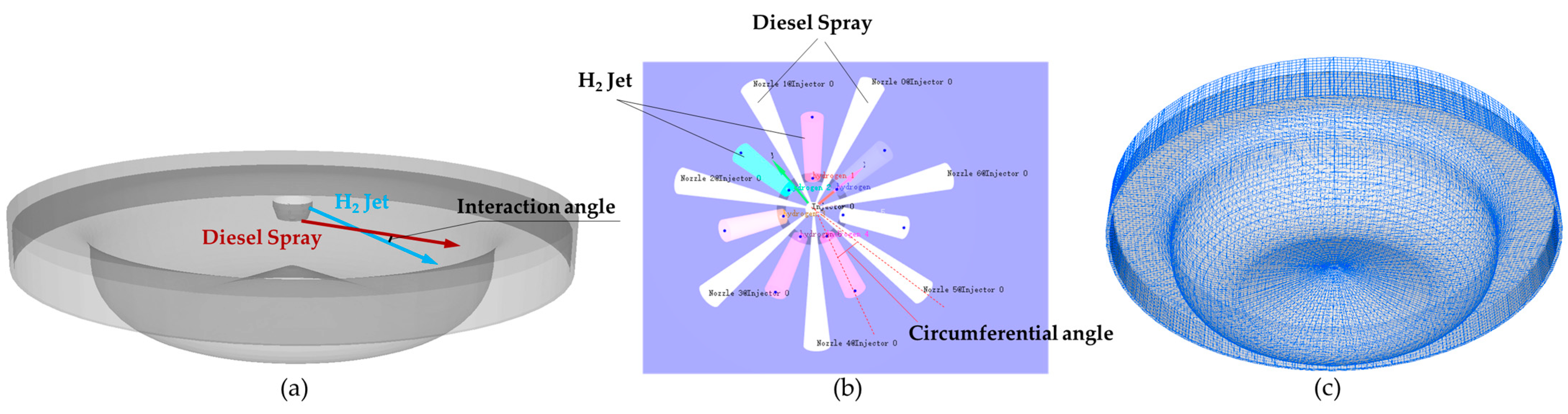
2.1. Mathematical Models

To improve the accuracy of turbulence modeling in internal combustion engines, the renormalization group (RNG) k-ε model was implemented. The model was enhanced from the standard k-ε approach by incorporating additional terms that account for flow curvature and rapid strain rates [27]. To accurately represent the fuel spray breakup process, the Kelvin–Helmholtz–Rayleigh–Taylor (KH-RT) breakup model was used. This model was designed to capture two primary instabilities, the Kelvin–Helmholtz instability and the Rayleigh–Taylor instability, which govern both primary and secondary droplet breakup [28]. Furthermore, the O’Rourke and Amsden model was utilized to refine the heat transfer process by considering both convective and conductive heat transfer mechanisms. Empirical correlations were employed in the model to calculate the convective heat transfer coefficient, enhancing the accuracy of heat transfer simulations within the combustion chamber. The SAGE chemistry solver was implemented to handle detailed reaction mechanisms. Several acceleration strategies, including adaptive zoning, dynamic mechanism reduction, and stiffness-based load balancing, were integrated into the solver to improve computational efficiency. Through this solver, complex combustion scenarios involving multiple species and reactions were accurately predicted, ensuring precise modeling of ignition timing, flame propagation, and pollutant formation. To model soot formation, the Hiroyasu soot model was applied. The model was developed to calculate the first-order rate of soot formation using empirical correlations based on Arrhenius-type equations. The processes of soot nucleation, growth, and oxidation were considered [29], making the model suitable for diesel and dual-fuel engine simulations. The diesel fuel was represented by n-heptane. The physical property of diesel fuel was represented by tetrad cane to simulate the spray development, atomization, vaporization, and the mixing of n-heptane with air [30]. The fuel chemistry used in this study is a reduced PRF mechanism proposed by Ra and Reitz [31], which consists of 41 species and 130 reactions. The thermal NOx model (Extend Zeldovich) [32] is used for the simulation of NOx.

2.2. Characterization Parameters of Combustion Process

(1)
Combustion characterization parameters
The following mathematical expressions quantify the flow field’s convective transport effect on flames ψ f l a m e :
ϕ f l a m e = T · U T × U + 1 / 2
ψ f l a m e = i = 1 n ϕ f l a m e × m i i = 1 n m i
where T is temperature gradient, U is velocity, m i is the fluid mass in cell i, and n is the total number of cells in the computational domain. The ϕ f l a m e ranges between 0 and 1. ϕ f l a m e = 1 indicates optimal convective transport effectiveness of the local flow field on flame propagation. ϕ f l a m e = 0 signifies minimal convective transport effectiveness in the current flow configuration. This dimensionless parameter quantitatively characterizes the coupling efficiency between flow dynamics and thermal transport in combustion systems.
Combustion temperature serves as a critical parameter for characterizing combustion states. To quantify the spatial uniformity of temperature distribution, we define the combustion temperature standard deviation σ T as follows:
σ T = i = 1 n T i T ¯ 2 n
where T i and T ¯ represent the temperature of each cell and the domain-averaged temperature (mass-weighted mean), respectively, and n is the total cell number in the domain. A higher σ T value indicates greater temperature non-uniformity within the cylinder.
The temperature uniformity index U I T is as follows:
U I T = 1 σ T T ¯
When U I T approaches 1 it indicates a more uniform temperature distribution, whilst when U I T approaches 0 it indicates a non-uniform temperature distribution.
(2)
Mixing characterization parameters
Uniformity of the air–fuel mixture
The uniformity of the air–fuel mixture was assessed using the standard deviation of the mixture’s composition as a quantitative parameter. In this study, the equivalence ratio is defined based on the mass flow rates of hydrogen and diesel fuel relative to their respective stoichiometric air requirements. This approach allows for a comprehensive understanding of the combustion characteristics of each fuel within the dual-fuel system. Since the masses of hydrogen and diesel are maintained constant throughout the study, this ratio effectively measures the impact of injection parameters on the mixing state of the diesel vapor. It is expressed as follows:
σ m i x = i = 1 n λ i λ ¯ 2 n
where λ i and λ ¯ denote the equivalence ratio for each computational cell and the mass-weighted average equivalence ratio of the entire computational domain, respectively. An increase in the value of σ m i x indicates a more uneven distribution of the in-cylinder air–fuel mixture.
The uniformity index of the gas mixture U I m i x is as follows:
U I m i x = 1 σ m i x λ ¯
When the value of U I m i x approaches 1 it indicates a more uniform distribution of the air–fuel mixture within the combustion chamber, whilst when U I m i x deviates significantly from 1 it suggests a more uneven distribution.
Species mixing degree
According to Curie’s theorem, coupling effects exist between vectors in space. The mixing of oil and gas is not only related to convective transport but also influenced by component diffusion mechanisms. Therefore, φ d i e s e l , O 2 , φ H 2 , O 2 and, φ d i e s e l , H 2 are defined to characterize the coupling effects of diesel–oxygen, hydrogen–oxygen, and diesel–hydrogen diffusion on mixing. They are expressed as follows:
φ d i e s e l , O 2 = Y d i e s e l · Y O 2 Y d i e s e l × Y O 2 + 1 / 2
φ H 2 , O 2 = Y H 2 · Y O 2 Y H 2 × Y O 2 + 1 / 2
φ d i e s e l , H 2 = Y d i e s e l · Y H 2 Y d i e s e l × Y H 2 + 1 / 2
where Y d i e s e l , Y H 2 , and Y O 2 represent the mass fraction of diesel vapor, hydrogen, and oxygen, respectively. The value of φ d i e s e l , O 2 , φ H 2 , O 2 , and φ d i e s e l , H 2 range from 0 to 1. Values approaching 1 indicate a stronger co-directional coupling between the two components, while values nearing 0 signify a stronger counter-directional coupling. According to Curie’s principle, co-directional coupling occurs when the gradient vectors of two components point in the same direction, while counter-directional coupling occurs when their gradient vectors point in opposite directions. This coupling effect arises from diffusion driven by concentration gradients in space.
To evaluate the overall oil–gas mixing effectiveness within the cylinder at a specific moment, the parameters φ d i e s e l , H 2 , φ d i e s e l , O 2 , and φ H 2 , O 2 were calculated for each computational cell and their mass-weighted averages across the entire computational domain were determined to obtain the average values of ψ d i e s e l , H 2 , ψ d i e s e l , O 2 , and ψ H 2 , O 2 . A higher value of ‘b’ indicates a more uneven distribution of the air–fuel mixture within the cylinder. The following equations were used:
ψ d i e s e l , H 2 = i = 1 n φ d i e s e l , H 2 × m i i = 1 n m i
ψ d i e s e l , O 2 = i = 1 n φ d i e s e l , O 2 × m i i = 1 n m i
ψ H 2 , O 2 = i = 1 n φ H 2 , O 2 × m i i = 1 n m i
where m i is the fluid mass within computational cell i.

3. Results and Discussion

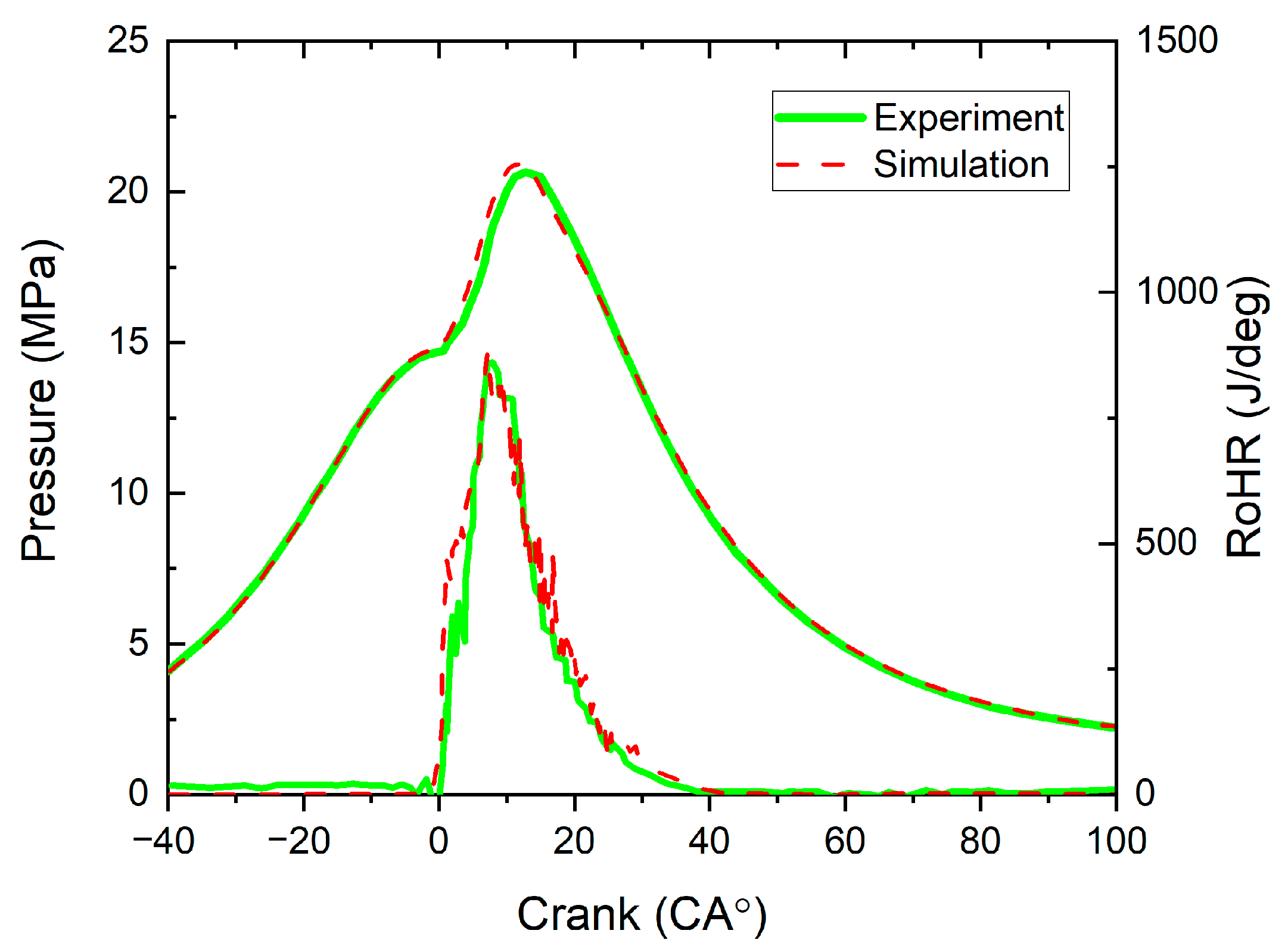
3.1. Grid Independence Analysis and Model Validation

In this study, the baseline diesel combustion (CDC) system parameters were adopted from Reference [33]. Experiments were carried out using a single-cylinder research engine derived from a standard Volvo D13 heavy-duty diesel platform. The engine operated under conventional diesel combustion (CDC) conditions with a low swirl level and was equipped with a low compression ratio piston (11.5:1). The key engine parameters are listed in Table 1. The combustion chamber of the engine is designed with seven hydrogen injection orifices and seven diesel injection orifices, all centrally arranged. This nozzle features a converging structure with a co-axial dual-layer design. The upper layer houses seven hydrogen injection holes, while the lower layer contains seven diesel injection holes. Since the injection holes in both layers are aligned, an angular deviation exists between the hydrogen jet and the diesel spray axis, leading to their interaction during injection. The spatial configuration parameters of the dual-layer nozzle in this study consist of two key angles: the circumferential angle in the horizontal plane and the interaction angle in the vertical plane (see Figure 1a,b). The circumferential angle governs the relative positioning between hydrogen jets and diesel sprays along the horizontal axis, while the interaction angle controls their vertical alignment.
Table 1 presents the test rig specifications and operating conditions for the CDC and HDDF combustion cases. In this study, the interaction angle was adjusted by controlling the diesel spray’s umbrella angle while keeping the hydrogen jet’s umbrella angle fixed. The interaction angle was varied from 0° to 10°. The injection timings for both diesel and hydrogen were fixed across all simulation cases.
The computational mesh for the engine cylinder is constructed using CONVERGE software. A Cartesian grid generation method is employed, which automatically partitions the domain into structured cells. To improve accuracy in key regions—such as the combustion chamber and injector zones—CONVERGE’s adaptive mesh refinement (AMR) strategy is utilized. This technique dynamically adjusts the mesh throughout the simulation, refining or coarsening based on local flow behavior to optimize computational efficiency without compromising detail in critical areas. A mesh independence study is conducted using five different grid densities (refer to Table 2). In particular, the finest grid spacing in areas like the hydrogen jet and spray breakup regions is reduced from 400 μm to 100 μm.
Figure 2 presents the computed average in-cylinder pressures and the peak in-cylinder pressures obtained using various mesh densities. The relative errors are assessed with respect to the results from the finest mesh (Case E). As the number of cells increases, the deviation decreases significantly. Notably, beyond Case C the difference reduces sharply to just 0.76%. Further mesh refinement yields no significant improvement in the in-cylinder pressure predictions. In contrast, when using grids coarser than Case B, the deviation surpasses 5%. Considering both accuracy and computational cost, the mesh configuration of Case C, when the cell number is 1.85 × 10⁶, is selected as the most suitable for this investigation. The computational simulations were conducted on a Dell PowerEdge R730 chassis configured with dual Intel Xeon E5-2682 v4 CPUs (2.5 GHz base frequency, 64 total threads), 128 GB DDR4 memory, and an NVIDIA GeForce RTX 3090 GPU (24 GB GDDR6X). Parallel computing utilized 52 threads, with the Case C simulation requiring 26 h and 12 min to complete.
The CDC mode (see Table 2) is used for model validation. This part evaluates the accuracy of the current simulation model by comparing the computed in-cylinder pressure and rate of heat release (RoHR) with experimental data reported in [33]. As illustrated in Figure 3, the numerical predictions show good agreement with the experimental trends. A slight over-prediction of the heat release is observed during the initial combustion phase, especially around the top dead center. The model forecasts a peak pressure of 20.92 MPa at an 11.82° crank angle after top dead center (CA ATDC), whereas the experimental peak reaches 20.66 MPa at 12.73° CA ATDC. The corresponding discrepancies in peak pressure magnitude and timing are 1.26% and 7.15%, respectively.

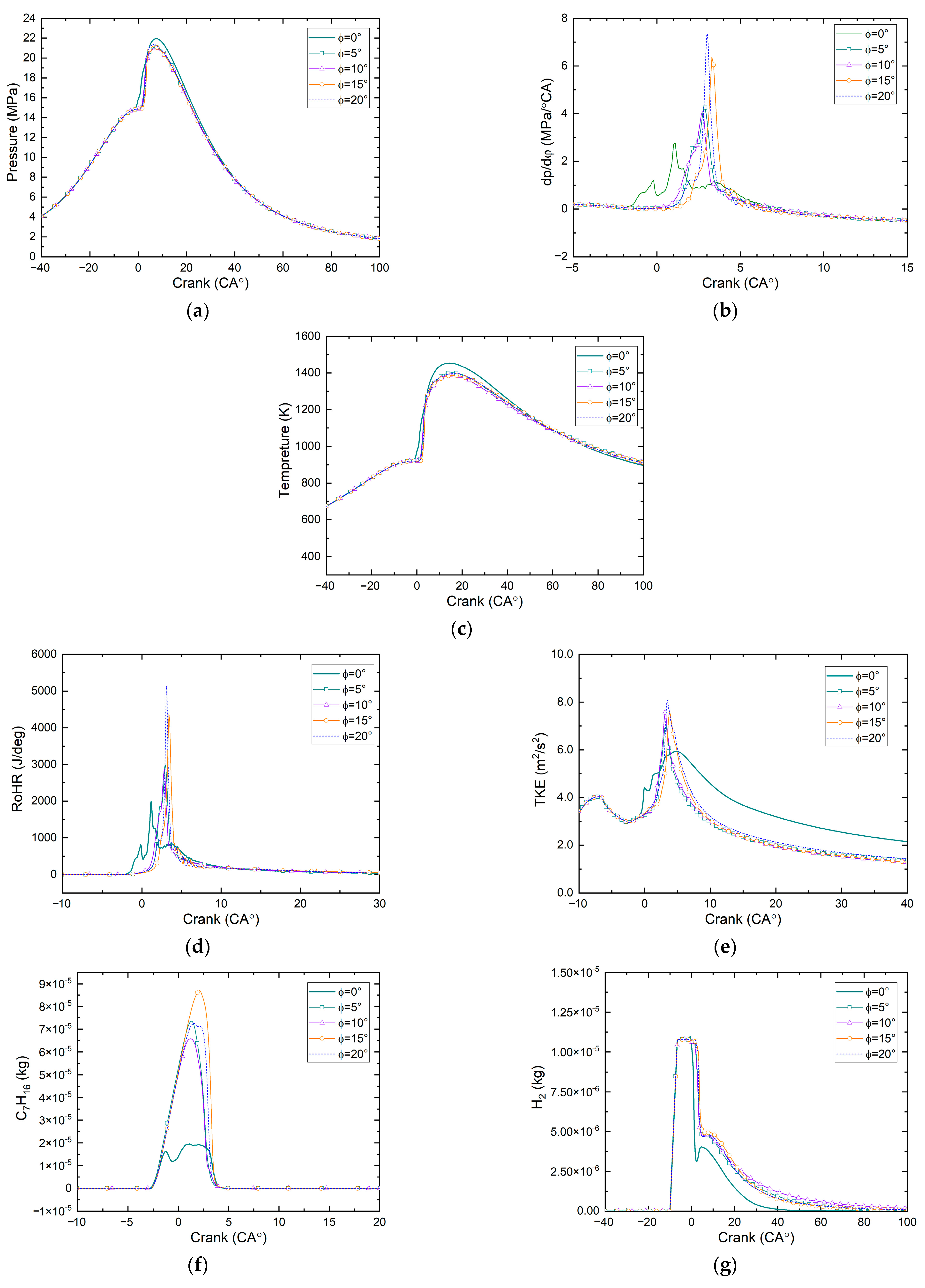
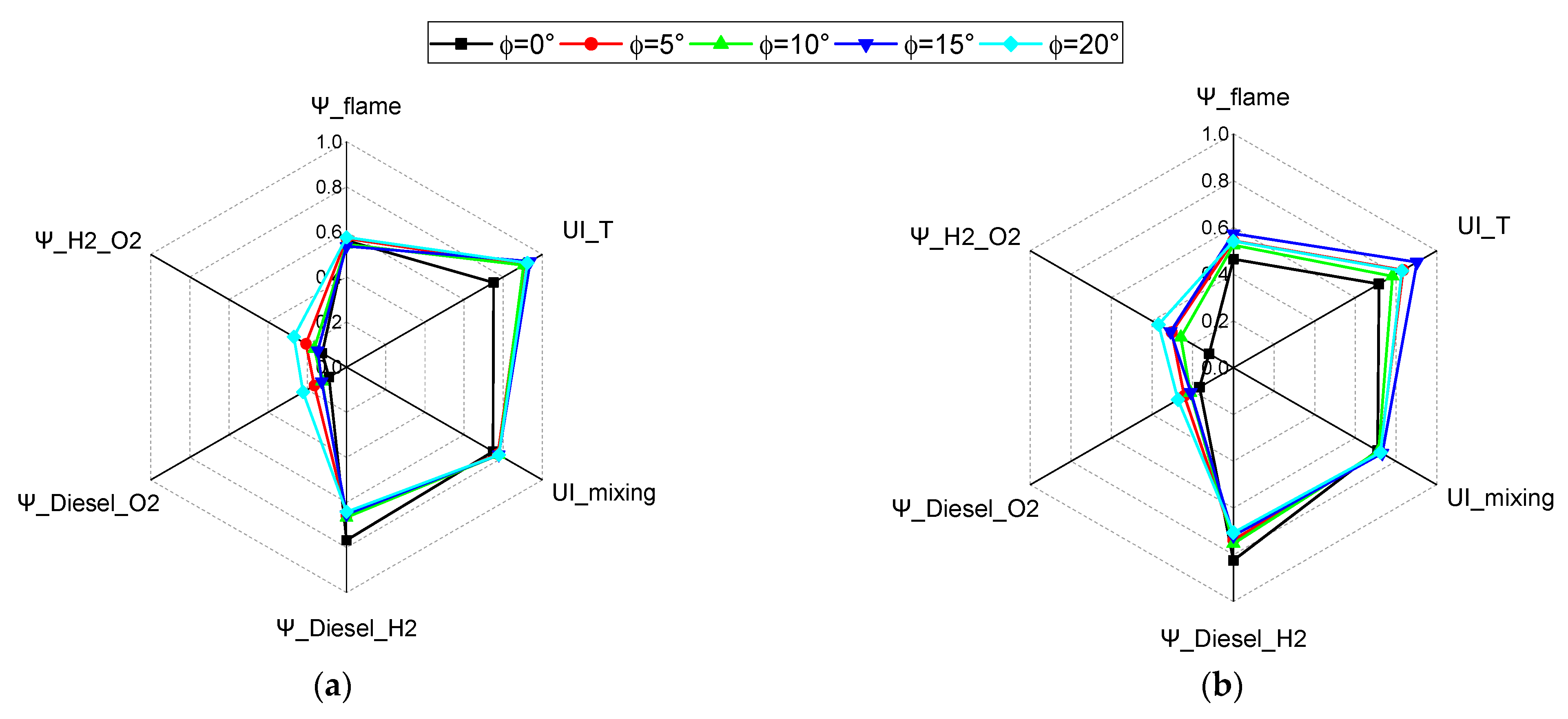
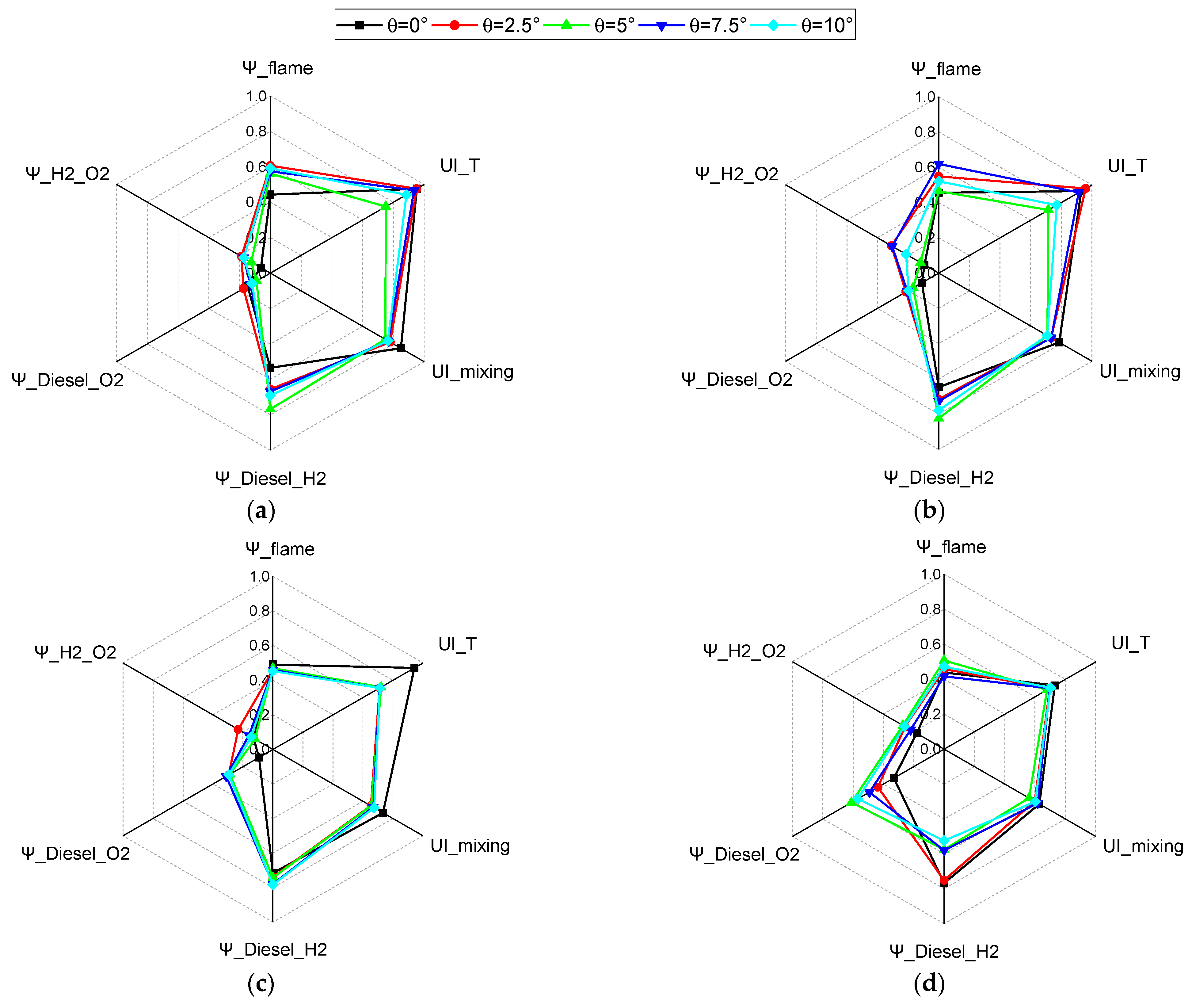
3.2. Effect of Circumferential Angle Between Hydrogen Jets and Diesel Sprays

This section provides a comparison and analysis of the impact of the circumferential angle between hydrogen jet and diesel spray on combustion and emission performance. The circumferential angle between the hydrogen jets and diesel sprays varies from 0° to 20°, with an interval of 5° between each case.
As shown in Figure 4, the peak average in-cylinder gas pressure initially decreases and then increases with the circumferential angle. At a circumferential angle of 0°, both the in-cylinder pressure and temperature reach their maximum values, the heat release begins earliest, and the high turbulence kinetic energy is sustained the longest. As shown in the pressure rise rate results (Figure 4b), the peak values of the pressure rise rate curves gradually increase as the circumferential angle increases from 0° to 20°, while the corresponding crank angles of these peaks exhibit a progressively delayed trend. This indicates that larger circumferential angles enhance premixed combustion intensity. However, excessive pressure rise rates can induce mechanical losses, combustion noise, and vibration issues in the engine. Under this condition, the interaction between the hydrogen jet and diesel spray is more pronounced, enhancing turbulence and intensifying the combustion process. As a result, the remaining masses of C7H16 and H2 are lower compared to cases with other circumferential angles. When the circumferential angle is set to 15°, the combustion is most delayed, accompanied by reduced turbulence intensity, lower in-cylinder pressure and temperature, and slower consumption of C7H16 and H2. These results indicate weaker combustion; however, this condition also yields the lowest NOx and soot emissions, representing the most favorable emission performance among all cases.
For all cases, the spray Sauter mean diameter (SMD) shows non-zero values around −3° CA ATDC and after 2.5° CA ATDC. The former corresponds to the start of diesel injection, where the SMD rapidly peaks and then quickly diminishes. This behavior suggests that the hydrogen jet supplies additional kinetic energy to promote diesel droplet breakup, highlighting the benefits of the integrated injector configuration. After 2.5° CA ATDC, although SMD remains relatively high the overall diesel mass is minimal, and the large droplet sizes observed correspond to only a few remaining droplets, which have a negligible impact on combustion.
Due to the highest combustion temperature observed in the case with a 0° circumferential angle, a significant amount of thermal NOx is formed via the Zeldovich mechanism (N2 + O → NO + N; N + O2 → NO + O; N + OH → NO + H [33]). At elevated temperatures, reactions such as the dissociation of H2O and CO2 release more free oxygen atoms (O) which directly participate in the thermal decomposition of N2, accelerating NO formation. Although the case with a 0° circumferential angle produces the highest soot peak during combustion, enhanced oxidation during the late combustion phase significantly reduces soot levels. In contrast, the case with a 10° circumferential angle exhibits the largest soot mass during the combustion tail phase. The case with a 15° circumferential angle achieves the lowest NOx and soot levels, with reductions of 29.6% and 34.5%, respectively, compared to the 0° case. The formation mechanisms of NOx under hydrogen–diesel dual-fuel operation include the following: (1) Under hydrogen-rich conditions, especially in regions with low temperature or incomplete combustion during the combustion process, HO2 can form in large quantities via the reaction H + O2 + M → HO2 + M. This promotes the conversion of NO to NO2, thereby increasing NO2 emissions [34]. (2) N2O pathway: Under hydrogen-enriched conditions, particularly in zones of low temperature or incomplete combustion, N2O may significantly contribute as a precursor to NO formation. Molecular nitrogen reacts with atomic oxygen in the presence of a third body to produce N2O, which subsequently reacts with O atoms to form NO. The relevant reactions include N2 + O + M → N2O + M and N2 + HO2 → N2O + OH [35]. (3) Prompt NO pathway: Prompt NO is typically formed in the flame front region via reactions between fuel-derived radicals (e.g., CH) and molecular nitrogen. While this pathway is more prominent in conventional hydrocarbon fuels, the addition of hydrogen in a diesel–hydrogen dual-fuel system can enhance the concentrations of reactive radicals such as CH and OH, as well as increase flame front reactivity. This, in turn, indirectly promotes the rate of prompt NO formation [36].
To compare the effects of the circumferential angle between hydrogen jets and diesel sprays on combustion and work performance, a statistical analysis was conducted on the computed heat release rate and in-cylinder mean pressure curves. The center of combustion, also known as the 50% combustion point (CA50), refers to the crank angle position at which the cumulative heat release reaches 50% of the total heat released during combustion. This is determined by integrating the heat release rate curve to calculate the cumulative heat release and identifying the crank angle at which it equals half of the total heat release. In evaluating work output, the mean effective pressure (MEP) and indicated power during the high-pressure cycle were analyzed. As shown in Table 3, at a circumferential angle of 0° ignition occurs earliest (−0.3° CA ATDC), with the highest MEP and indicated power recorded at 6.39 MPa and 47.26 kW, respectively. Conversely, at a circumferential angle of 10°, the indicated power is at its lowest, and the center of combustion (4.11° CA ATDC) is closest to the top dead center, indicating the shortest combustion duration. This suggests that a circumferential angle of 0° results in the highest degree of constant-volume combustion and the most effective work output. As the circumferential angle increases from 0° to 20°, the center of combustion is latest at φ = 10°, with the longest combustion duration. Under these conditions, the MEP and indicated power during the high-pressure cycle are at their lowest.
To comprehensively analyze the interplay between work output (characterized by mean effective pressure, MEP) and NOx/soot emissions a normalization process was applied to these parameters. The normalization methodology was designed to align with the following performance optimization objectives: MEP was normalized using the linear scaling formula f n o r m = x x min / x max x min , where higher values indicate improved power output, while NOx and soot emissions were normalized via f n o r m = 1 x / x max to prioritize emission reduction. This unified framework ensures all normalized values approach 1 for optimal performance, facilitating multi-objective optimization analysis. By applying these methods to the MEP data from Table 3 and the NOx/soot emission profiles in Figure 4j–k, the normalized results were compiled into Table 4 and Figure 5. Practical optimization results remain adaptable to application-specific priorities through adjustable weighting coefficients governing the relative importance of power output versus emission control objectives.
Figure 6 illustrates the in-cylinder temperature distribution at various times and positions. At φ = 0°, the combustion chamber exhibits the most rapid and extensive flame development, with the spatial distribution resembling a symmetrical pattern of seven liquid spray flames, as seen in the top-down view of Figure 6b. When φ > 0°, the flame propagation within the combustion chamber slows compared to the φ = 0° case and noticeable interference and overlap occur between the flames of different fuel jets, also depicted in the top-down view of Figure 6b. The hydrogen jet, due to its broader flammability limits, occupies airspace within both the diesel spray regions and between the fuel jets, leading to localized oxygen depletion. This results in a deterioration of the air–fuel mixture and a subsequent slowing of the combustion process.
To improve the comparability of species distribution results presented in Figure 7 we have applied normalized scales and updated both figures accordingly. The normalization reference values for C6H17, H2, NOx, and soot are based on their respective maximum mass fractions during the combustion process, which are 0.459, 0.0378, 0.000163, and 0.00119, respectively. In the φ = 0° case, at top dead center (TDC) the distribution areas of C7H16 and H2 are larger, attributed to the impact and transport effects of the hydrogen jet on the underlying diesel spray and its constituents. At 10° CA after TDC the hydrogen distribution is more concentrated near the combustion chamber walls. This observation indicates that the interaction between hydrogen and diesel jets facilitates their spatial transport. Due to the higher combustion temperatures under φ = 0° conditions, NOx concentrations and distribution areas are more pronounced compared to other cases. The competition between hydrogen and oxygen leads to a high degree of overlap between regions of high soot concentration and hydrogen distribution. Therefore, to reduce soot emissions in the current dual-fuel injection mode, it is advisable to regulate the spatial distribution of hydrogen.
Figure 8 presents radar charts depicting the in-cylinder mixing and flame distribution parameters calculated using Equations (1) through (12) for various circumferential angles between hydrogen jets and diesel sprays. In these charts, ψ_flame quantifies the flow field’s convective transport effect on flames, computed via Equation (2). UI_T and UI_mixing are derived from Equations (4) and (6), respectively. Additionally, ψ_Diesel_H2, ψ_Diesel_O2, and ψ_H2_O2 are calculated using Equations (10)–(12), respectively. Analyzing the flow field’s convective transport effect on flames, ψ_flame values range between 0.4 and 0.6 across different circumferential angles and time points. Notably, during the initial combustion phase (−2° CA ATDC and TDC) ψ_flame is relatively higher, indicating a stronger influence of the flow field on flame propagation. At φ = 0°, during the early combustion stages (−2° CA ATDC and TDC) UI_T is significantly lower than at other φ values. Concurrently, ψ_Diesel_O2 and ψ_H2_O2 are markedly smaller, suggesting that aligning diesel–hydrogen jets with O2 on the same axial plane enhances the interaction of fuel and air, leading to a reduction in temperature uniformity and resulting in a non-uniform temperature distribution. Although other φ values exhibit higher temperature uniformity, severe flame interference is observed in the circumferential direction between diesel and hydrogen jets. Considering the indicated power of the high-pressure cycle and combustion duration, the φ = 0° configuration, despite compromising spatial flame uniformity, mitigates the circumferential oxygen competition between hydrogen and diesel. This promotes more efficient diesel combustion. Prior to 10° CA ATDC, the interactions between hydrogen and oxygen, as well as diesel and oxygen, are less pronounced in the φ = 0° case compared to other φ values. This implies that co-axial alignment of diesel and hydrogen jets (φ = 0°) diminishes the oxygen competition effect of hydrogen in the regions between diesel sprays but intensifies it within the diesel spray zones. This phenomenon contributes to the peak soot formation observed in Figure 4k and the premature release of fuel energy depicted in Figure 4d.
Data on fuel–air mixing and combustion characterization parameters under different circumferential angles are listed in Table 5.

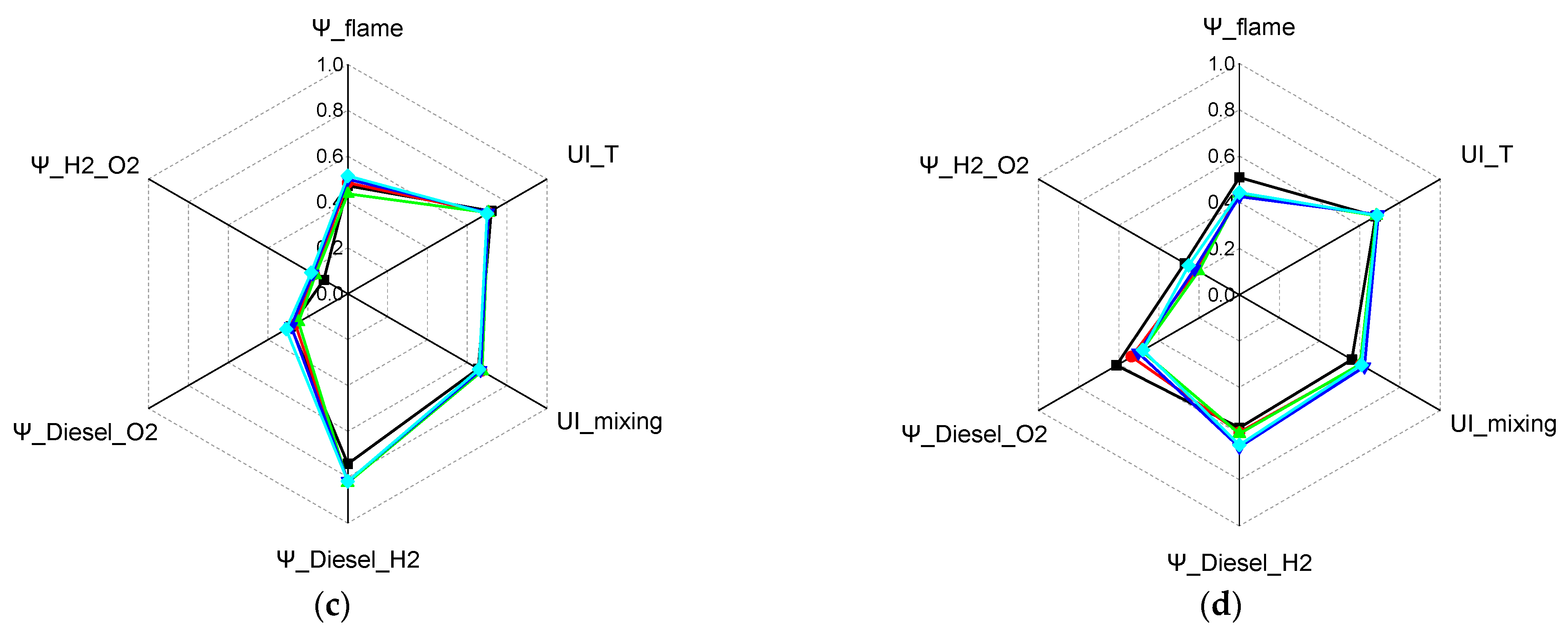
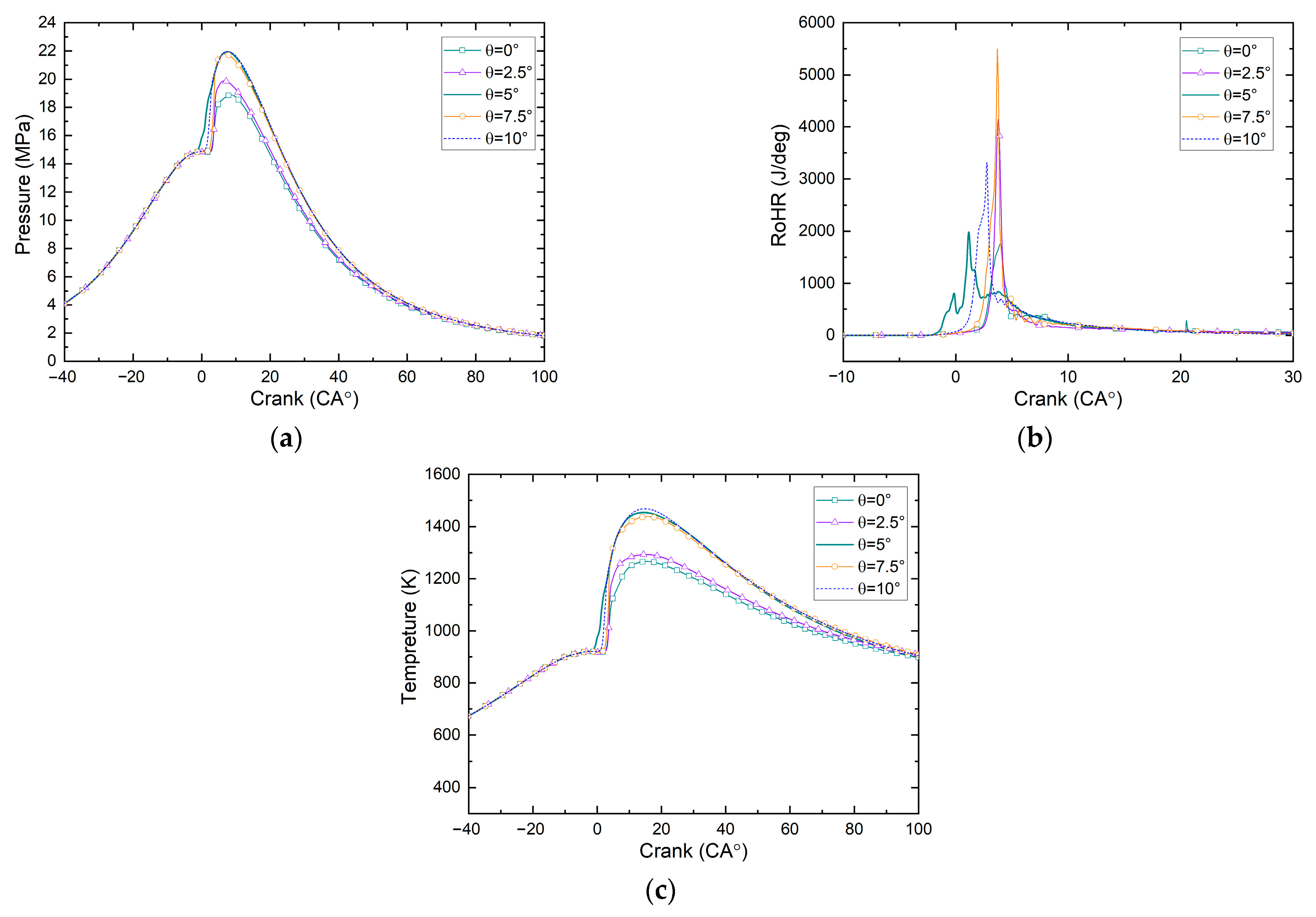
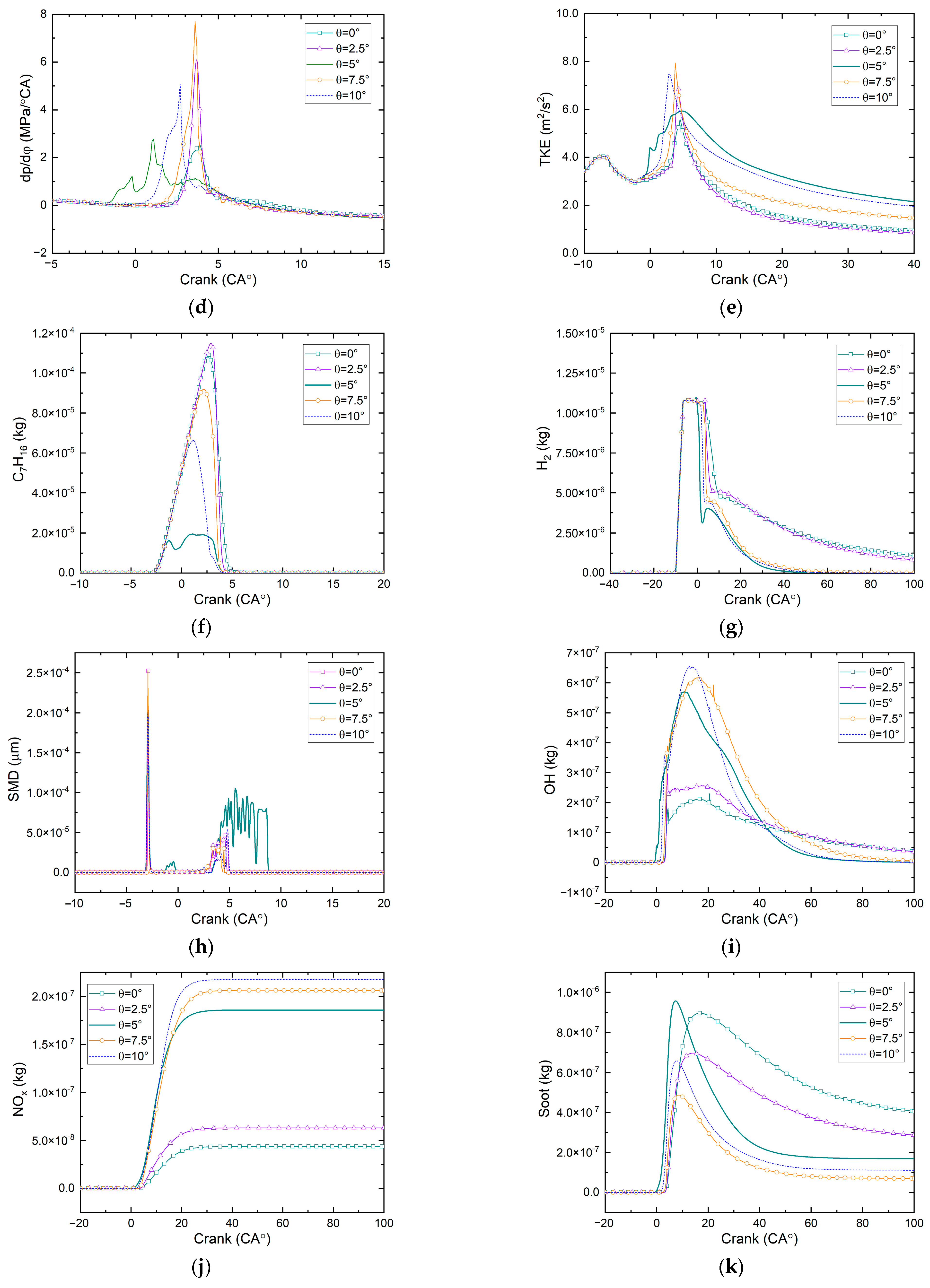
3.3. Effect of Interaction Angle Between Hydrogen Jets and Diesel Sprays

Figure 9 illustrates that the interaction angle (θ) between hydrogen jets and diesel sprays significantly influences the heat release process during combustion. The circumferential angle (φ) between the hydrogen jets and diesel sprays is 0°. Specifically, in-cylinder pressure and temperature are notably higher at θ values of 5°, 7.5°, and 10° compared to θ values of 0° and 2.5°. At θ = 0° the peak in-cylinder pressure and temperature are the lowest, measuring 18.87 MPa and 1267 K, respectively. The minimum peak pressure rise rate is observed at an interaction angle of 0°, with other angles resulting in higher values. The maximum peak occurs at an interaction angle of 7.5°. When θ is increased to 5° or greater the heat release occurs earlier and the turbulence kinetic energy during the initial combustion phase is significantly enhanced. This leads to a reduction in the residual masses of fuel vapor and hydrogen after TDC, along with an increase in OH concentration. These findings suggest that vertical interference between hydrogen jets and diesel sprays promotes combustion efficiency. Consequently, NOx emissions increase for θ values of 5° and above, while soot emissions decrease. The impact of the interaction angle between hydrogen and diesel sprays on emissions can be attributed to the following mechanisms: (1) Combustion temperature and equivalence ratio distribution: The interaction angular offset between the hydrogen and diesel sprays (with moderate θ interference) results in relatively stronger local interactions between the high-reactivity hydrogen jet and the diesel-rich zones. This promotes earlier ignition and faster heat release. The locally rich combustion zones and enhanced heat release tend to raise the peak flame temperature moderately, yet in some regions increased mixing with excess hydrogen leads to a locally lower oxygen concentration and leaner environment, suppressing the NO formation pathway. (2) Soot formation enhancement due to quenching and overlap: The overlapping spray plumes at this φ/θ combination also lead to higher fuel residence times and partial quenching in the central impingement region. Diesel entrainment into cooler or partially reacted zones can promote the formation of soot precursors such as C2H2, especially under fuel-rich and low-O2 conditions. Moreover, the hydrogen jet may locally elevate temperatures without sufficiently oxidizing soot precursors, leading to higher soot mass fraction [37]. (3) Trade-off mechanism (NOx–Soot): The competing behavior observed—NOx reduction and soot increase—aligns with the classic trade-off in dual-fuel systems where richer mixtures or delayed oxidation suppress NOx but hinder soot oxidation.
Table 6 indicates that the ignition timing initially advances and then retreats as the interaction angle (θ) increases. At θ = 5° ignition occurs earliest at −0.3° CA ATDC. The center of combustion advances progressively with increasing θ, but the rate of advancement diminishes, approaching approximately 4° CA ATDC. Combustion duration first lengthens and then shortens with increasing θ, reaching its maximum of 6.39° CA at θ = 5°, with θ = 7.5° yielding a similar duration of 6.36° CA. The indicated power of the high-pressure cycle peaks at 47.69 kW under these conditions. Deviations from this θ value result in reduced indicated power. These findings suggest that when the circumferential angle (φ) between the hydrogen jets and diesel sprays is 0°—meaning their axes lie within the same vertical plane—the optimal interaction angle (θ) for maximizing work output is 7.5°.
The same normalization method used for the variables in Table 3 was applied to the MEP data in Table 5 and the NOx/Soot results in Figure 9j–k, with the normalized results compiled into Table 7 and Figure 10. Practical optimization results remain adaptable to application-specific priorities through adjustable weighting coefficients governing the relative importance of power output versus emission control objectives.
Figure 11 presents the calculated distributions of flames and components on axial cross-sectional planes within the combustion chamber under varying interaction angle (θ) conditions. At θ = 5°, a substantial flame area is observed at TDC. Both the heat release rate curve shown in Figure 8c and the ignition timing results in Table 3 indicate that combustion initiates earliest at θ = 5°. Although the mean effective pressure of the high-pressure cycle is highest at this θ value, increased negative work performed before TDC reduces the indicated power of the high-pressure cycle. Additionally, the expansion work before TDC is higher, leading to a decrease in indicated power. Influenced by changes in the diesel spray umbrella angle, combustion gradually shifts upward within the combustion chamber. To further analyze the coupling effects between hydrogen jets and diesel sprays and their impact on the combustion process, refer to the results in Figure 12. Figure 11d,e reveal that when θ ≥ 5° NOx generation within the cylinder significantly surpasses levels observed at θ = 0° and 2.5°, while soot concentration is markedly lower under these conditions.
Figure 12 illustrates that when the interaction angle (θ) is 0° the counter-directional coupling between hydrogen jets and diesel sprays is significant, as evidenced by ψ_H2_O2 and ψ_Diesel_O2 values approaching 0. Conversely, a ψ_Diesel_H2 value near 0.5 indicates a weaker coupling between parallel hydrogen jets and diesel sprays. When θ ≥ 2.5°, prior to TDC, ψ_H2_O2, ψ_Diesel_O2, and ψ_Diesel_H2 values exceed those observed at θ = 0°, suggesting enhanced co-directional coupling between non-parallel hydrogen jets and diesel sprays which facilitates improved mixing of hydrogen and diesel with air. Regarding the flow’s convective transport effect on flames (ψ_flame), θ = 0° yields the lowest transport effect while the other four θ values exhibit similar transport effects. Notably, at TDC, the flow’s convective transport effect on flames is strongest at θ = 7.5°. However, relying solely on the equivalence ratio uniformity index (UI_mixing) to assess work performance is challenging. A UI_mixing value close to 1 may indicate a relatively uniform spatial distribution of diesel vapor; however, excessive residual diesel vapor at θ = 0° (see Figure 11b) reflects suboptimal combustion conditions. This suggests that UI_mixing alone is insufficient for evaluating work performance as combustion quality is also influenced by the amount of unburned fuel remaining in the chamber.
Data on fuel–air mixing and combustion characterization parameters under different interaction angles are listed in Table 8.

4. Conclusions

This study systematically investigated the effects of circumferential and interaction angles between hydrogen jets and diesel sprays on combustion characteristics, emission formation, and work performance in a hydrogen–diesel dual-fuel compression ignition (CI) engine. Key findings and results are summarized below:
(1)
A circumferential angle of φ = 0° yielded the highest in-cylinder pressure (20.92 MPa) and temperature (1267 K), along with the earliest ignition timing (−0.3° CA ATDC) and shortest combustion duration (18.11° CA). This configuration maximized turbulence kinetic energy and fuel–air mixing, leading to 47.26 kW indicated power—the highest among tested cases. However, φ = 0° also produced 29.6% higher NOx and 34.5% higher soot emissions compared to φ = 15°, where emissions were minimized due to reduced flame interference and oxygen competition.
(2)
An interaction angle of θ = 7.5° achieved the best balance between combustion efficiency and work output, with 47.69 kW indicated power and 15.28° CA combustion duration. Vertical interference at θ ≥ 5° enhanced flame propagation and reduced residual fuel mass, but NOx emissions increased by ~35% relative to θ = 0°. At θ = 0° weak coupling between hydrogen and diesel sprays resulted in poor mixing (ψ_Diesel_H2 ≈ 0.5) and 40.76 kW indicated power—the lowest performance.
(3)
Configurations with higher combustion temperatures (e.g., φ = 0°, θ ≥ 5°) increased thermal NOx via the Zeldovich mechanism but reduced soot by ~30% due to improved oxidation. For example, φ = 15° reduced soot by 34.5% but sacrificed 12% indicated power compared to φ = 0°. The equivalence ratio uniformity index (UI_mix) exceeded 0.85 for φ = 10–20°, but combustion efficiency was compromised by fuel-rich zones. Co-axial alignment (φ = 0°) improved local mixing (ψ_Diesel_O2 > 0.6) but intensified oxygen competition near spray regions.
(4)
With the φ = 0° and θ = 7.5° combination, the high-pressure loop indicated that the work reaches its maximum value, accompanied by NOx and soot emissions of 2.06 × 10⁻⁷ kg and 6.88 × 10⁻⁸ kg, respectively. In contrast, the φ = 0° and θ = 5° configuration achieves a 9.7% reduction in NOx while maintaining a minimal 0.9% drop in indicated work, albeit at the expense of a 144.2% increase in soot production.

Author Contributions

Conceptualization, X.L.; methodology, Q.Z.; software, Z.L.; validation, Q.Z. and X.L.; formal analysis, Q.Z.; investigation, Q.Z.; data curation, Q.Z. and Y.X.; writing—original draft preparation, Q.Z.; writing—review and editing, Q.Z.; visualization, Y.X.; supervision, X.L.; project administration, X.L. All authors have read and agreed to the published version of the manuscript.

Funding

This research received no external funding.

Institutional Review Board Statement

Not applicable.

Informed Consent Statement

Not applicable.

Data Availability Statement

The original contributions presented in this study are included in the article. Further inquiries can be directed to the corresponding author.

Conflicts of Interest

The authors declare no conflicts of interest.

References

  1. Dimitriou, P.; Kumar, M.; Tsujimura, T.; Suzuki, Y. Combustion and emission characteristics of a hydrogen-diesel dual-fuel engine. Int. J. Hydrogen Energy 2018, 43, 13605–13617. [Google Scholar] [CrossRef]
  2. Akal, D.; Öztuna, S.; Büyükakın, M.K. A review of hydrogen usage in internal combustion engines (gasoline-Lpg-diesel) from combustion performance aspect. Int. J. Hydrogen Energy 2020, 45, 35257–35268. [Google Scholar] [CrossRef]
  3. Wright, M.L.; Lewis, A.C. Decarbonisation of heavy-duty diesel engines using hydrogen fuel: A review of the potential impact on NO x emissions. Environ. Sci. Atmos. 2022, 2, 852–866. [Google Scholar] [CrossRef]
  4. Gnanamoorthi, V.; Vimalananth, V.T. Effect of hydrogen fuel at higher flow rate under dual fuel mode in CRDI diesel engine. Int. J. Hydrogen Energy 2020, 45, 16874–16889. [Google Scholar] [CrossRef]
  5. Jamrozik, A.; Grab-Rogaliński, K.; Tutak, W. Hydrogen effects on combustion stability, performance and emission of diesel engine. Int. J. Hydrogen Energy 2020, 45, 19936–19947. [Google Scholar] [CrossRef]
  6. Vargün, M.; Yapmaz, A.; Kalender, V.; Yılmaz, I.T. Investigation of the effects of using hydrogen enriched fuel blends in a diesel engine on engine performance, combustion and exhaust emissions. Int. J. Hydrogen Energy 2025, 97, 1399–1410. [Google Scholar] [CrossRef]
  7. Estrada, L.; Moreno, E.; Gonzalez-Quiroga, A.; Bula, A.; Duarte-Forero, J. Experimental assessment of performance and emissions for hydrogen-diesel dual fuel operation in a low displacement compression ignition engine. Heliyon 2022, 8, e09285. [Google Scholar] [CrossRef]
  8. Grab-Rogalinski, K.A.; Tutak, W.; Jamrozik, A. Comparative Analysis of Combustion Process of Dual Fuel Diesel Engine Fueled by Diesel/Hydrogen and Biodiesel/Hydrogen; SAE Technical Paper; SAE: Warrendale, PA, USA, 2020. [Google Scholar]
  9. Ahmed, S.A.; Zhou, S.; Tsegay, S.; Ahmad, N.; Zhu, Y. Effects of hydrogen-enriched biogas on combustion and emission of a dual-fuel diesel engine. Energy Sources Part A Recovery Util. Environ. Eff. 2024, 46, 5644–5659. [Google Scholar] [CrossRef]
  10. Tutak, W.; Jamrozik, A.; Grab-Rogaliński, K. Effect of natural gas enrichment with hydrogen on combustion process and emission characteristic of a dual fuel diesel engine. Int. J. Hydrogen Energy 2020, 45, 9088–9097. [Google Scholar] [CrossRef]
  11. Subramanian, B.; Thangavel, V. Experimental investigations on performance, emission and combustion characteristics of Diesel-Hydrogen and Diesel-HHO gas in a Dual fuel CI engine. Int. J. Hydrogen Energy 2020, 45, 25479–25492. [Google Scholar] [CrossRef]
  12. Karagöz, Y.; Sandalcı, T.; Yüksek, L.; Dalkılıç, A. Engine performance and emission effects of diesel burns enriched by hydrogen on different engine loads. Int. J. Hydrogen Energy 2015, 40, 6702–6713. [Google Scholar] [CrossRef]
  13. Akhtar, M.U.S.; Asfand, F.; Khan, M.I.; Mishra, R.; Ball, A.D. Performance and emissions characteristics of hydrogen-diesel dual-fuel combustion for heavy-duty engines. Int. J. Hydrogen Energy 2025, in press. [CrossRef]
  14. Li, Z.; Liu, J.; Ji, Q.; Sun, P.; Wang, X.; Xiang, P. Influence of hydrogen fraction and injection timing on in-cylinder combustion and emission characteristics of hydrogen-diesel dual-fuel engine. Fuel Process. Technol. 2023, 252, 107990. [Google Scholar] [CrossRef]
  15. Zhang, J.; Yu, X.; Guo, Z.; Li, D.; Wang, T.; Gong, T.; You, T. Effect of Exhaust Gas Recirculation and Spark Timing on Combustion and Emission Performance of an Oxygen-Enriched Gasoline Engine. ACS Omega 2022, 7, 42208–42220. [Google Scholar] [CrossRef] [PubMed]
  16. Rorimpandey, P.; Zhai, G.; Kook, S.; Hawkes, E.R.; Chan, Q.N. Effects of energy-share and ambient oxygen concentration on hydrogen-diesel dual-fuel direct-injection (H2DDI) combustion in compression-ignition conditions. Int. J. Hydrogen Energy 2024, 49, 1346–1361. [Google Scholar] [CrossRef]
  17. Tang, Q.; Liu, H.; Li, M.; Yao, M. Study on the double injection strategy of gasoline partially premixed combustion under a light-duty optical engine. SAE Int. J. Engines 2016, 9, 2185–2193. [Google Scholar] [CrossRef]
  18. Bayramoğlu, K.; Yılmaz, S. Emission and performance estimation in hydrogen injection strategies on diesel engines. Int. J. Hydrogen Energy 2021, 46, 29732–29744. [Google Scholar] [CrossRef]
  19. Babayev, R.; Andersson, A.; Dalmau, A.S.; Im, H.G.; Johansson, B. Computational comparison of the conventional diesel and hydrogen direct-injection compression-ignition combustion engines. Fuel 2022, 307, 121909. [Google Scholar] [CrossRef]
  20. Wang, Y.; Evans, A.; Srna, A.; Wehrfritz, A.; Hawkes, E.; Liu, X.; Kook, S.; Chan, Q.N. A Numerical Investigation of Mixture Formation and Combustion Characteristics of a Hydrogen-Diesel Dual Direct Injection Engine; SAE Technical Paper; SAE: Warrendale, PA, USA, 2021. [Google Scholar]
  21. Mancaruso, E.; Rossetti, S.; Vaglieco, B.M. Analysis of Dual Fuel Hydrogen/Diesel Combustion Varying Diesel and Hydrogen Injection Parameters in a Single Cylinder Research Engine; SAE Technical Paper; SAE: Warrendale, PA, USA, 2024. [Google Scholar]
  22. Das, S.; Das, B. Effect of injection parameters on the hydrogen enriched dual-fuel CRDI diesel engine. Energy Sources Part A Recovery Util. Environ. Eff. 2023, 45, 10176–10199. [Google Scholar] [CrossRef]
  23. Fink, G.; Jud, M.; Sattelmayer, T. Fundamental study of diesel-piloted natural gas direct injection under different operating conditions. J. Eng. Gas Turbines Power 2019, 141, 091006. [Google Scholar] [CrossRef]
  24. Rorimpandey, P.; Yip, H.L.; Srna, A.; Zhai, G.; Wehrfritz, A.; Kook, S.; Hawkes, E.R.; Chan, Q.N. Hydrogen-diesel dual-fuel direct-injection (H2DDI) combustion under compression-ignition engine conditions. Int. J. Hydrogen Energy 2023, 48, 766–783. [Google Scholar] [CrossRef]
  25. Versteeg, H.K. An Introduction to Computational Fluid Dynamics the Finite Volume Method, 2/E; Pearson Education India: Delhi, India, 2007. [Google Scholar]
  26. Steve Karman, L., Jr. SPLITFLOW-A 3D unstructured Cartesian/prismatic grid CFD code for complex geometries. In Proceedings of the 33rd Aerospace Sciences Meeting and Exhibit, Reno, NV, USA, 9–12 January 1995; p. 343. [Google Scholar]
  27. Widiawaty, C.D.; Siswantara, A.I.; Gunadi, G.G.R.; Andira, M.A.; Budiarso; Budiyanto, M.A.; Syafei, M.H.G.; Adanta, D. Optimization of inverse-Prandtl of Dissipation in standard k-ε Turbulence Model for Predicting Flow Field of Crossflow Turbine. CFD Lett. 2022, 14, 112–127. [Google Scholar] [CrossRef]
  28. Jia, M.; Pan, H.; Bian, Y.; Zhang, Z.; Chang, Y.; Liu, H. Calibration of the constants in the kelvin-helmholtz rayleigh-taylor (KH-RT) breakup model for diesel spray under wide conditions based on advanced data analysis techniques. At. Sprays 2022, 32, 1–27. [Google Scholar] [CrossRef]
  29. Hiroyasu, H.; Kadota, T.; Arai, M. Development and use of a spray combustion modeling to predict diesel engine efficiency and pollutant emissions: Part 1 combustion modeling. Bull. JSME 1983, 26, 569–575. [Google Scholar] [CrossRef]
  30. Li, Y.; Li, H.; Guo, H. A numerical investigation on NO2 formation reaction pathway in a natural gas–diesel dual fuel engine. Combust. Flame 2018, 190, 337–348. [Google Scholar] [CrossRef]
  31. Ra, Y.; Reitz, R.D. A reduced chemical kinetic model for IC engine combustion simulations with primary reference fuels. Combust. Flame 2008, 155, 713–738. [Google Scholar] [CrossRef]
  32. Anetor, L.; Odetunde, C.; Osakue, E.E. Computational analysis of the extended Zeldovich mechanism. Arab. J. Sci. Eng. 2014, 39, 8287–8305. [Google Scholar] [CrossRef]
  33. Lam, N.; Tunestal, P.; Andersson, A. Simulation of System Brake Efficiency in a Double Compression-Expansion Engine-Concept (DCEE) Based on Experimental Combustion Data; SAE Technical Paper; SAE: Warrendale, PA, USA, 2019. [Google Scholar]
  34. Li, H.; Liu, S.; Liew, C.; Li, Y.; Wayne, S.; Clark, N. An investigation on the mechanism of the increased NO2 emissions from H2-diesel dual fuel engine. Int. J. Hydrogen Energy 2018, 43, 3837–3844. [Google Scholar] [CrossRef]
  35. Lopatin, O.P. Chemistry of the process of formation of nitrogen oxides in the combustion chamber of gas-diesel. J. Phys. Conf. Ser. 2020, 1515, 052004. [Google Scholar] [CrossRef]
  36. Moussa, S.G.; Leithead, A.; Li, S.M.; Chan, T.W.; Wentzell, J.J.; Stroud, C.; Zhang, J.; Lee, P.; Lu, G.; Brook, J.R.; et al. Emissions of hydrogen cyanide from on-road gasoline and diesel vehicles. Atmos. Environ. 2016, 131, 185–195. [Google Scholar] [CrossRef]
  37. Wang, Y.; Gu, M.; Zhu, Y.; Cao, L.; Zhu, B.; Wu, J.; Lin, Y.; Huang, X. A review of the effects of hydrogen, carbon dioxide, and water vapor addition on soot formation in hydrocarbon flames. Int. J. Hydrogen Energy 2021, 46, 31400–31427. [Google Scholar] [CrossRef]
Figure 1. Computational domain and nozzle positioning. (a) Computational domain, nozzle positioning, and interaction angle of hydrogen jets and diesel sprays. (b) Circumferential angle of hydrogen jets and diesel sprays. (c) Grids.
Sustainability 17 06059 g001
Figure 2. A comparison of the peak in-cylinder pressures for different cell numbers. (a) The computed average in-cylinder pressures across varying mesh densities; (b) the peak in-cylinder pressure values along with their relative deviations.
Sustainability 17 06059 g002
Figure 3. Comparison of the experimentally obtained in-cylinder mean pressure and heat release rate.
Sustainability 17 06059 g003
Figure 4. Average in-cylinder fluid properties under different circumferential angles between hydrogen jets and diesel sprays. (a) In-cylinder pressure. (b) Pressure rise rate. (c) In-cylinder temperature. (d) Rate of heat release. (e) Turbulence kinetic energy. (f) Diesel vapor mass. (g) Hydrogen mass. (h) SMD of diesel fuel spray. (i) OH mass. (j) NOx mass. (k) Soot mass.
Sustainability 17 06059 g004aSustainability 17 06059 g004b
Figure 5. A 3D scatter plot of normalized performance–emission tradeoffs across circumferential angle variations.
Sustainability 17 06059 g005
Figure 6. The in-cylinder temperature distribution at various time and positions. (a) The temperature distribution along the axial plane of a combustion chamber. (b) The temperature distribution along the circumferential plane of a combustion chamber.
Sustainability 17 06059 g006
Figure 7. Progression of normalized species distributions at the central vertical slices of the cylinder at various times. (a) C7H16, (b) H2, (c) NOx, and (d) SOOT.
Sustainability 17 06059 g007aSustainability 17 06059 g007b
Figure 8. Characterization parameters of the combustion process at various time under different circumferential angles. (a) −2° CA ATDC, (b) TDC, (c) 5° CA ATDC, and (d) 10° CA ATDC.
Sustainability 17 06059 g008aSustainability 17 06059 g008b
Figure 9. Average in-cylinder fluid properties under different interaction angles between hydrogen jets and diesel sprays. (a) In-cylinder pressure. (b) Pressure rise rate. (c) In-cylinder temperature. (d) Rate of heat release. (e) Turbulence kinetic energy. (f) Diesel vapor mass. (g) Hydrogen mass. (h) SMD of diesel fuel spray. (i) OH mass. (j) NOx mass. (k) Soot mass.
Sustainability 17 06059 g009aSustainability 17 06059 g009b
Figure 10. A 3D scatter plot of normalized performance–emission tradeoffs across interaction angle variations.
Sustainability 17 06059 g010
Figure 11. Progression of temperature and normalized species distributions at the central vertical slices of the cylinder. (a) Temperature. (b) C6H17. (c) H2. (d) NOx. (e) Soot.
Sustainability 17 06059 g011aSustainability 17 06059 g011b
Figure 12. Characterization parameters of the combustion process under different interaction angles at various time. (a) −2° CA ATDC. (b) TDC. (c) 5° CA ATDC. (d) 10° CA ATDC.
Sustainability 17 06059 g012
Table 1. Research engine rig specifications and operating conditions for the CDC and HDDF combustion cases.
CDC [33]HDDF
Cylinder bore/mm131
Stroke/mm158
Connecting rod length/mm267.5
Compression ratio11.5:1
Engine speed/RPM1200
Piston temperature/K800
Cylinder liner temperature/K610
Cylinder head temperature/K740
Number of diesel and H2 nozzle orifices7
Diesel orifice diameter/mm0.265
Diesel spray umbrella angle/°135, 140, 145, 150, 155
Diesel injection timing/° CA ATDC−3
H2 energy share, HES/%040
H2 injection mass/mg041.3
H2 orifice diameter/mm01
H2 spray umbrella angle/°0135
H2 injection timing/° CA ATDC −10
In-cylinder gas pressure at IVC/bar6.86.8
In-cylinder gas temperature at IVC/K446446
Diesel injection mass/mg275.6165.4
Table 2. Summary of grids and computational parameters.
CaseMean Grid Size, μmCell Number
A4000.82 × 106
B3001.31 × 106
C2001.85 × 106
D1502.37 × 106
E1002.85 × 106
Table 3. Summary of combustion and work performance under different circumferential angles between hydrogen jets and diesel sprays.
φ = 0°φ = 5°φ = 10°φ = 15°φ = 20°
Ignition time
(° CA ATDC)
−0.31.91.62.31.9
Center of combustion
(° CA ATDC)
4.114.574.744.454.12
Combustion duration (° CA)18.1125.8428.9124.1023.38
Mean effective pressure of high-pressure cycle (MPa)6.396.276.216.226.23
Indicated power of high-pressure cycle (kW)47.2646.4845.9246.3746.34
Table 4. Normalized MEP, NOx, and Soot emissions under different circumferential angles.
Circumferential Angles (φ)fMEPfNOxfSoot
100.092
0.3330.1660.200
10°00.2520
15°0.0560.2920.404
20°0.1110.2940.272
Table 5. Data on fuel–air mixing and combustion characterization parameters under different circumferential angles.
Crank Angle (° CA ATDC)Circumferential Angles (°)Ψ_FlameUI_TUI_MixingΨ_Diesel_H2Ψ_Diesel_O2Ψ_H2_O2
−200.5610.7500.7480.7680.0890.124
50.5700.9070.7720.6590.1640.207
100.5450.9040.7780.6670.1250.164
150.5360.9380.7780.6530.1270.147
200.5760.9230.7780.6420.2220.269
000.4640.7160.7090.8240.1670.119
50.5430.8350.7220.7370.2420.303
100.5240.7830.7140.7520.2120.259
150.5730.9030.7320.7180.2100.309
200.5410.8290.7240.7050.2730.369
500.4700.7210.6550.7420.2860.120
50.4830.7050.6720.8180.2640.168
100.4360.7060.6740.8230.2470.163
150.4990.7060.6670.8170.2840.175
200.5140.6990.6590.8180.3090.184
1000.5070.6790.5600.5760.6110.272
50.4370.6860.6050.5950.5360.214
100.4380.6820.6020.6010.4850.203
150.4240.6920.6220.6590.5030.223
200.4420.6860.6070.6490.4790.253
Table 6. Summary of combustion and work performance under different interaction angles (θ) between hydrogen jets and diesel sprays.
θ = 0°θ = 2.5°θ = 5°θ = 7.5°θ = 10°
Ignition time
(° CA ATDC)
2.93.1−0.31.62.5
Center of combustion
(° CA ATDC)
8.686.274.114.034.01
Combustion duration (° CA)25.0220.2718.1115.2816.97
Mean effective pressure of high-pressure cycle (MPa)5.926.026.396.366.30
Indicated power of high-pressure cycle (kW)40.7642.2947.2647.6947.33
Table 7. Normalized MEP, NOx, and soot emissions under different interaction angles.
Interaction Angle (θ)fMEPfNOxfSoot
00.7990
2.5°0.2130.710.289
10.1460.547
7.5°0.9360.0520.814
10°0.80900.702
Table 8. Data on fuel–air mixing and combustion characterization parameters under different interaction angles.
Crank Angle (° CA ATDC)Interaction Angles (°)Ψ_FlameUI_TUI_MixingΨ_Diesel_H2Ψ_Diesel_O2Ψ_H2_O2
−200.4430.9520.8480.5350.1480.061
50.6060.9510.7790.6550.1740.188
100.5610.7500.7480.7680.0890.124
150.5740.9340.7660.6690.1280.173
200.5910.8840.7640.6910.1190.172
000.4550.930.7860.6470.1100.093
50.5480.9590.7340.7160.2140.309
100.4640.7160.7090.8240.1670.119
150.6190.9140.7340.7260.2050.304
200.5200.7700.7080.7780.1970.213
500.4900.9430.7330.7160.0930.129
50.4610.7110.6530.7390.2960.232
100.4700.7210.6550.7420.2860.120
150.4600.7110.6690.7800.3120.161
200.4530.7120.6750.7830.2950.146
1000.4390.7300.6280.7680.3320.181
50.4580.6970.5970.7510.4370.258
100.5070.6790.5600.5760.6110.272
150.4170.6970.6180.5800.4930.221
200.4720.7020.6010.5250.5700.261
Disclaimer/Publisher’s Note: The statements, opinions and data contained in all publications are solely those of the individual author(s) and contributor(s) and not of MDPI and/or the editor(s). MDPI and/or the editor(s) disclaim responsibility for any injury to people or property resulting from any ideas, methods, instructions or products referred to in the content.

