1. Introduction
Fiber-reinforced polymeric composites play a critical role in the economy, primarily due to their light weight, durability, and potential for reuse and recycling [
1,
2]. Legislative initiatives from the European Union, such as the Net-Zero Industry Act (NZIA) and the Advanced Materials Strategy, emphasize the significant importance of composites in the energy, construction, and transportation sectors [
3]. This aligns with the EU’s strategic goals on circular economy and sustainable materials management. As a consequence of the widespread use of these materials, there is a growing need for the rational management of composite waste. However, composite recycling technologies (
Figure 1), including pyrolysis and solvolysis, need to be further developed and scaled up to effectively support a closed-loop material cycle for composite waste [
4,
5]. Additionally, efficient collection and sorting systems for end-of-life composites must be established, which may include, among other things, amendments to existing waste code regulations [
6]. The European Composites Industry Association (EuCIA) is actively engaged in building a pan-European value chain for composites, fostering cross-sector collaboration and promoting innovative recycling solutions [
7].
Some of the most commonly used composites are glass fiber-reinforced polyester resins (GFRP – Glass Fiber Reinforced Polymer) [
2,
4]. These materials are widely applied in construction (e.g., tanks, pipes, facades), transportation (e.g., vehicle bodies, wind turbine blades, ship hulls), power generation (e.g., insulators, turbine components), and sports equipment (e.g., skis, tennis racquets), among others [
8]. The advantages of laminate coatings based on polyester resin and glass fiber mats contribute to their growing popularity in the repair and reinforcement of steel underground fuel tank shells [
5,
9]. These benefits include excellent anti-corrosion protection of the steel shell and a significant improvement in its mechanical properties, including enhanced resistance to mechanical damage and increased pressure strength [
10]. For many years, an important aspect of applying composite coatings to single-shell tanks has also been to reduce the risk of soil contamination from leaking fuel (or other hazardous substances), which has been a serious environmental and economic concern due to the need for costly remediation and cleanup measures [
11]. In many cases, such leaks were caused by corrosion of the tank shell or mechanical damage resulting from prolonged operation and the influence of varying soil conditions [
12].
Corrosion degradation of steel surfaces in underground tanks is primarily caused by direct contact with chemically aggressive stored substances and the surrounding soil environment [
11,
13]. The corrosion rate of steel in soil is estimated to be 0.1–0.2 mm per year, and the process may accelerate in the presence of additional factors, such as stray currents, groundwater levels, seasonal variations, proximity to road infrastructure, and even the activity of microorganisms [
14,
15]. This issue particularly affects single-walled underground steel tanks, which are widely used at gas stations and liquid fuel storage facilities [
16]. Currently, technical regulations require the use of double-walled tanks equipped with continuous monitoring of the interstitial space between the walls, enabling early detection of potential leaks and thereby minimizing the risk of soil contamination with petroleum compounds [
17,
18].
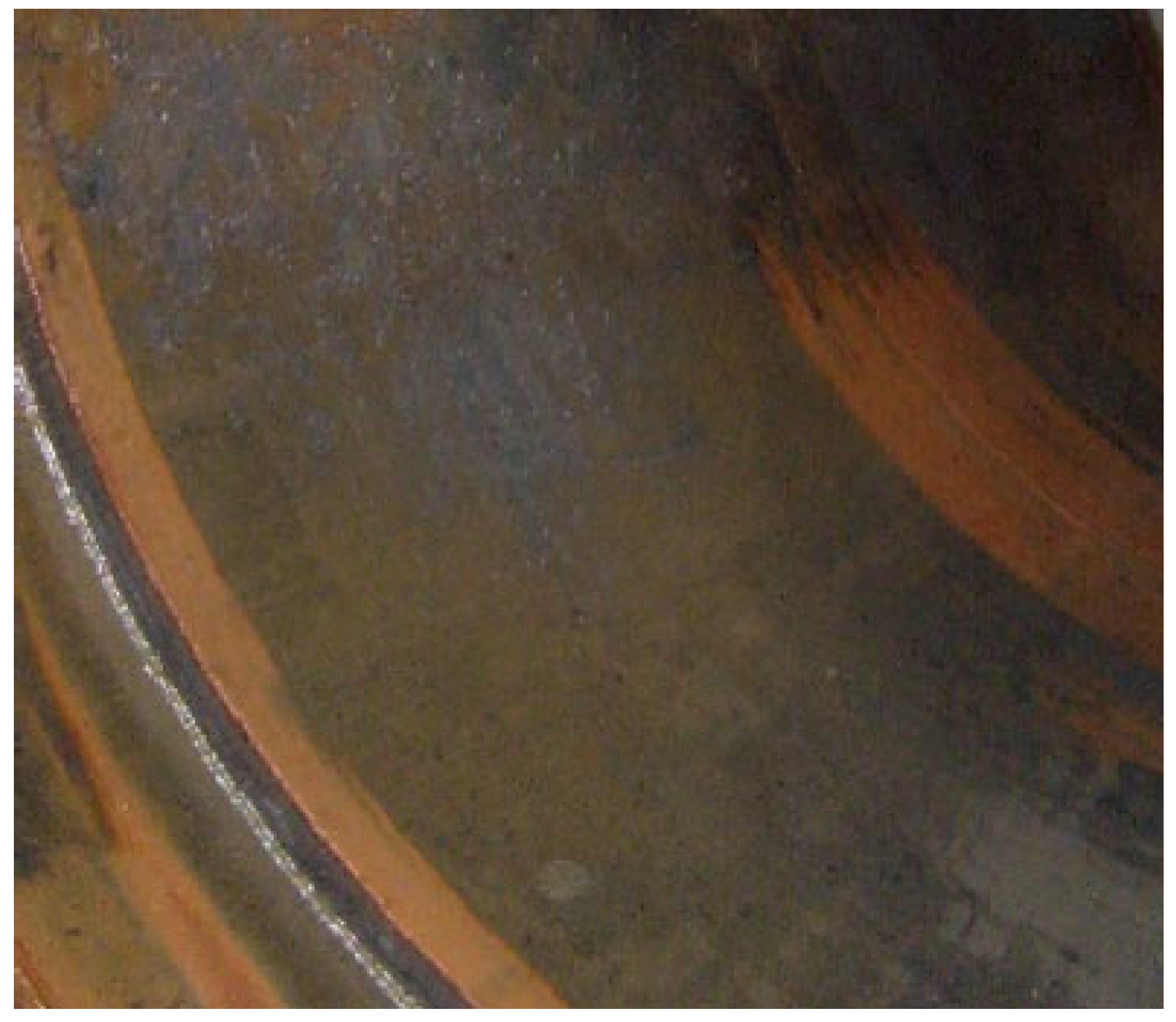
Over time, the internal steel shell of storage tanks is also subject to corrosion processes due to reactions with components of the stored medium, including water (
Figure 2) [
19]. In such cases, the application of a chemically resistant composite coating provides additional protection against further internal corrosion. Moreover, polyester-glass laminate can partially restore the original mechanical properties of a corroded steel shell, as confirmed by the authors’ calculations presented later in this study [
10]. Importantly, repairing a corroded steel tank with polyester-glass laminate avoids the substantially higher costs associated with replacing the entire tank with a new one [
10].
Tank refurbishment or repair begins with disconnecting the tank from the process installation. The tank is then drained of fuel (in the case of fuel tanks), vented, and thoroughly cleaned and degreased with chemical agents [
20]. Subsequently, the inner surface of the steel shell is subjected to abrasive blasting (sandblasting or shotblasting) to remove grease, dirt, and corrosion sites, and to expose its actual technical condition. In cases where existing composite reinforcement is being repaired, abrasive blasting is preceded by the manual removal of the deteriorated laminate coating.
After blasting, the thickness of the steel shell is measured, and its structural integrity is verified through calculation. A pneumatic leak test of the tank compartment is also performed as a standard procedure. A positive result of the pressure test allows the composite coating to be applied to the shell surface.
Adhesion between the polyester-glass laminate and the steel substrate is ensured by abrasive blasting of the steel surface, which increases surface roughness and promotes strong mechanical interlocking. Additionally, chemical bonding occurs during the impregnation of the substrate with polyester resin. The long-term operational durability of refurbished tanks confirms the effectiveness of this adhesion mechanism.
Before applying successive layers of the laminate composite, any cavities or defects in the steel shell are filled with a specialized leveling compound, and the entire surface is temporarily protected with a primer resin to prevent corrosion until the first composite layer is applied. Prepared nonwoven glass mats are hand-laid over the entire internal surface of the tank and impregnated with polyester resin mixed with a hardener. Subsequent layers of fiberglass reinforcement are applied in the same manner, ultimately forming a sealing composite of the designed thickness, consisting of several layers of glass mats of various weights, saturated with polyester resin (
Figure 3).
The final layer is covered with a glassy resin topcoat to precisely fill any voids, pores, or microcavities formed during laminate curing (
Figure 4). After curing, the tank is coated with a chemically resistant layer suitable for contact with the stored medium and compliant with anti-static protection requirements (
Figure 5) [
21].
The refurbished tank is then subjected to coating hardness tests and electrostatic leakage resistance tests. A positive result in these tests forms the basis for re-certification and re-commissioning of the tank for operational use.
Despite their undeniable advantages, polyester-glass-lined tanks also have a limited service life and must be replaced at the end of their life, or sooner for other operational reasons. Ideally, the materials from which they are made should be recovered and recycled in accordance with rational material management strategies [
2]. However, used polyester-glass laminates obtained from dismantled tanks represent problematic waste, and their effective management remains a significant challenge [
4]. This issue is analogous to the challenges associated with managing end-of-life wind turbine blades and laminate yacht hulls [
22].
Currently, polyester-glass laminates stored in landfills originate mainly from decommissioned single-wall tanks or repairs of composite coatings used in double-wall tanks. The removal of laminate coatings from dismantled tanks is essential to enable the reuse of scrap steel from tank shells in metallurgical processes. These composite coatings are particularly difficult to dispose of, not only because of their chemical composition and solid form, but also because they are often contaminated with fuel residues or other hazardous substances [
12]. Such waste is highly problematic for the environment and is classified as hazardous.
The recycling of polyester-glass laminates, as well as other glass fiber-reinforced polymer (GFRP) composites, is extremely challenging, especially when they are impregnated with petroleum derivatives or other chemicals. To date, no effective method has been developed to manage polyester-glass laminates that have been cured in contact with liquid fuels over many years of service. As a result, these materials are typically disposed of in landfills, where their resistance to degradation poses a significant ecological threat and a serious environmental concern.
This article presents the results of numerical analyses aimed at verifying the benefits of using polyester-glass laminates to reinforce the steel coatings of underground storage tanks. In addition, preliminary laboratory studies were conducted on the thermal conversion of waste polyester-glass laminates to assess their recyclability, with a particular focus on the potential for recovery of glass fibers.
2. Materials and Methods
2.1. Virtual Polyester-Glass Laminate
Numerical calculations were performed for a virtual (computational model) polyester-glass laminate (GFRP) to confirm its beneficial effect on the structural strength of the fuel tank steel shell. The virtual composite reinforcement, with a total thickness of 5 mm, was designed as a multilayer structure consisting of three layers of fiberglass mat (each 1 mm thick), alternating with four layers of polyester resin (each 0.5 mm thick).
The material constants assumed for the calculations were as follows: Young’s modulus E and Poisson’s ratio ν for the glass mat, E
g = 73 GPa, ν
g = 0.22, and for the polyester resin, E
r = 3.78 GPa, ν
r = 0.35. The GFRP laminate constructed in this way was assumed to behave as an isotropic material. The adopted parameters are consistent with the typical literature values for E-glass reinforced polyester composites [
23,
24].
2.2. Numerical Analysis of Tank Reinforced with Polyester-Glass Laminate
Numerical calculations of the effect of applying a virtual polyester-glass laminate on the stress distribution in the steel inner shell of a 20 m3 double-walled underground tank for liquid fuel storage were carried out using ANSYS Workbench 2022 R2 (ANSYS, Inc., Canonsburg, PA, USA) under an academic research license. It was assumed that the inner shell, with a thickness of 4 mm, was made of S235 structural steel and reinforced with the composite coating described previously.
The adopted steel shell thickness, reduced by 2 mm from its original nominal thickness, accounts for extensive corrosion losses on its inner surface caused by the aggressive nature of the stored product. The shell was assumed to be subjected to dead weight and an overpressure of 75 kPa, which is based on technical requirements of the Polish Office of Technical Inspection (UDT) for tank approval. This overpressure, approximately 187% of the operating pressure of the analyzed tank, is generated during a leakage test, the successful completion of which is a mandatory requirement for tank approval in Poland by the Office of Technical Inspection (UDT). While the selected 20 m3 tank model reflects a common configuration in practice, it should be noted that the results may vary for tanks of different sizes or geometries.
Due to the symmetry of both the load and the geometry of the tank, a 1/4 model of the inner shell was created, including a cylindrical section with an internal diameter of 2500 mm, as well as the bottom and a manhole stub with a cover (
Figure 6). Surface finite elements were used for the modeling.
An elastic-plastic material model was adopted for the steel shell, characterized by the following properties: Young’s modulus E = 210 GPa, Poisson’s ratio ν = 0.3, and yield strength of 235 MPa.
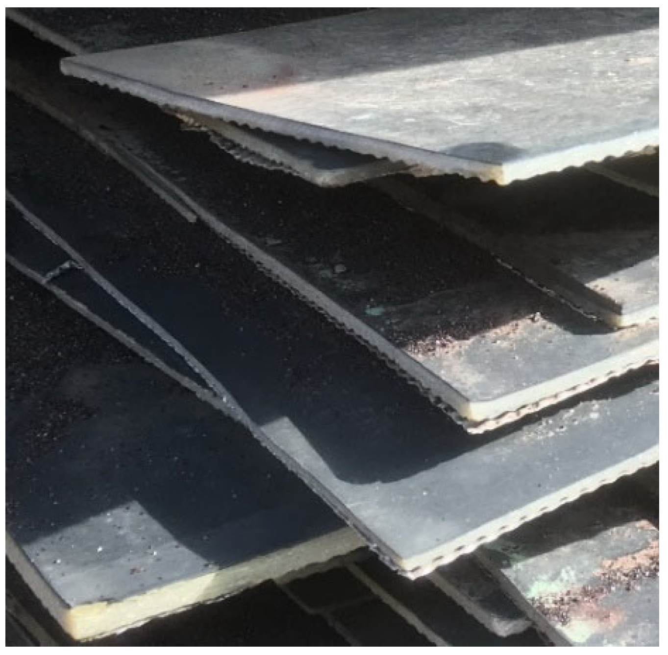
2.3. Waste Polyester-Glass Laminate
A polyester-glass laminate (GFRP), recovered from a fuel tank with a nominal capacity of 20 m
3 and an inner steel shell diameter of 2500 mm, previously used to store Pb95 unleaded gasoline, was used in the experimental study. The service life of the laminate shell was approximately 5 years. After decommissioning, the damaged laminate was stored as a pile in a landfill for 1.5 years (
Figure 7), from which an approximately 5 kg sample consisting of several randomly selected fragments was collected for testing. It should be noted that the 1.5-year storage period may have led to some surface weathering or partial degradation of the matrix, potentially affecting the results.
2.4. Laboratory Testing of Waste Polyester-Glass Laminate
A homogeneous GFRP analytical sample, prepared as described above, was used for proximate and ultimate analyses, as well as for thermal conversion studies conducted in a thermogravimetric reactor under various process conditions. All analytical procedures were carried out in accordance with methods accredited by the Polish Center for Accreditation (PCA), ensuring high quality and reproducibility of the results. Control samples were not included in this preliminary study; however, future work will incorporate control experiments to benchmark conversion efficiency.
Thermogravimetric analysis of the GFRP sample was conducted using a TG 209 F1Libra thermobalance (Netzsch-Gerätebau GmbH, Selb, Germany). Analytical samples with a mass of 6 mg were tested. The thermal decomposition experiments of the GFRP sample were carried out under oxygen-free (pyrolysis), reducing (gasification), and oxidizing (combustion) atmospheres. The specific conditions for each thermal treatment are presented below:
- (a)
Pyrolysis:
Holding the sample at 40 °C for 10 min under an argon flow of 75 cm3/min;
Heating the sample from 40 °C to 1000 °C at a rate of 10 K/min with an argon flow of 75 cm3/min;
Holding the sample at 1000 °C for 10 min with an argon flow of 75 cm3/min;
Combustion the sample at 1000 °C in a stream of synthetic air (80% N2 + 20% O2) with an air flow of 50 cm3/min and an argon flow of 25 cm3/min.
- (b)
Gasification:
Holding the sample at 40 °C for 10 min with a CO2 flow of 50 cm3/min and argon flow of 25 cm3/min;
Heating the sample from 40 °C to 1000 °C at a rate of 10 K/min with a CO2 flow of 50 cm3/min and an argon flow of 25 cm3/min;
Combustion the sample at 1000 °C in a stream of synthetic air (80% N2 + 20% O2) with an air flow of 50 cm3/min and an argon flow of 25 cm3/min.
- (c)
Combustion:
Holding the sample at 40 °C for 10 min with a synthetic air flow of 50 cm3/min and an argon flow of 25 cm3/min;
Heating the sample from 40 °C to 1000 °C at a rate of 10 K/min with a synthetic air flow of 50 cm3/min and an argon flow of 25 cm3/min.
The sequence of thermal treatments was fixed; future studies should consider a randomized process order to eliminate potential bias.
In order to assess the degree of transformation of the components in the GFRP samples, the solid products resulting from pyrolysis and combustion were subjected to microscopic examination using two types of microscopes:
A stereoscopic microscope: X200 (Opta Tech, Warsaw, Poland);
A polarizing microscope: AxioImager M1m (Carl Zeiss Microscopy GmbH, Jena, Germany).
Microscopic observations with the X200 stereoscopic microscope were performed under white light for solid residues after conversion, in their “as received” form. The samples were placed on an observation dish on the microscope stage, and observations were conducted at magnifications of ×20 and ×40.
For the microscopic analysis using the AxioImager M1m polarized microscope, the samples were first embedded in a synthetic (acrylic) resin. The embedded samples were then ground and polished using a Struers grinding-polishing system, with diamond and silicon oxide suspensions. The microstructural observations of the samples, prepared as cross-sections, were carried out in white light, at a magnification of ×500.
4. Discussion
The numerical calculations confirmed that the application of composite coatings on the inner surface of steel storage tanks significantly reduces the maximum Huber–Mises stresses in their structure. In the analyzed case, the tank’s structure was reinforced with a polyester-glass laminate, leading to a substantial reduction in stress values from 208 MPa to 105 MPa. This represents an almost twofold reduction compared to the uncoated tank. The findings suggest that the implementation of polyester-glass laminates can effectively extend the service life of storage tanks while mitigating the risk of failure due to corrosion or mechanical damage. However, despite their beneficial properties for such applications, polyester-glass laminates pose significant challenges in terms of recycling once they reach the end of their service life.
The proximate and ultimate analyses of the tested polyester-glass laminate (
Table 1 and
Table 2) confirm its relatively high volatile content (72.1%) and significant carbon fraction (59.4%), which is characteristic of polymer-based composites. In comparison to conventional thermosetting composites, such as epoxy-glass laminates, the examined material displays comparable organic composition but a marginally elevated ash residue (21.7%), suggesting a heightened proportion of inorganic fillers, predominantly glass fibers. The minimal sulfur content (0.03%) suggests a low risk of sulfur-based emissions during thermal processing, which makes the material potentially less harmful compared to other polymer composites containing flame retardants or sulfur-based resins. These properties are critical in assessing the feasibility of thermal recycling methods and the efficiency of glass fiber recovery from polyester-glass laminates.
A study of the thermogravimetric analysis of the degradation of waste polyester-glass laminates revealed distinct differences in their decomposition behavior depending on the process conditions. This finding is of paramount importance in the context of the primary objective of recycling these materials, namely the efficient recovery of glass fibers.
Glass fibers utilized in the fabrication of polyester-glass laminates demonstrate disparate degrees of chemical and thermal stability. For instance, E-glass fibers begin to experience mass loss and structural degradation at temperatures exceeding 600–700 °C. At temperatures ranging from 800 to 900 °C, a process of recrystallization and loss of structural integrity may occur, while at temperatures above 1000 °C, the fibers undergo melting, thereby effectively preventing their recovery [
23,
24]. The mechanical strength of glass fibers is also affected by temperature, with a general decrease observed as the temperature rises. Within the temperature range of 200 to 400 °C, a slight reduction in strength is observed, primarily due to internal thermal stresses. Above 400 °C, microcracks begin to form, and at higher temperatures (>600 °C), there is structural degradation leading to a significant loss of mechanical properties [
25].
In light of the aforementioned findings, it is evident that the thermal recycling of waste polyester-glass laminates for glass fiber recovery should be conducted using pyrolysis. This process prevents excessive heating of the glass fibers (>600 °C), thereby minimizing structural damage and preserving their mechanical properties. Conversely, gasification and combustion expose the fibers to considerably higher temperatures, resulting in their degradation and potential loss of mechanical integrity.
A salient point pertains to the environmental merits of pyrolysis as a recycling method [
26]. A comparison of pyrolysis with combustion and gasification reveals that the former process offers significant environmental benefits in the treatment of plastic-based composites. Conversely, combustion, despite its widespread implementation, demands elevated temperatures (850–1100 °C), which induce complete oxidation of the polymeric composition. This process generates substantial CO
2 emissions and compromises the integrity of embedded reinforcements, such as glass fibers. Gasification, while more efficient, still produces CO
2 and secondary pollutants if syngas is not adequately treated. Conversely, pyrolysis, a process that occurs under oxygen-free conditions at moderate temperatures (400–700 °C), yields significantly lower direct emissions. A notable benefit of pyrolysis is its capacity for the recovery of valuable hydrocarbons and inert residues. This process is particularly well-suited for polymer-glass fiber composites, where the separation of materials is desired. As previously emphasized in [
27], pyrolysis emerges as the most environmentally favorable and technologically versatile pathway for the conversion of plastic waste into valuable resources.
Although not quantified in this study, the energy demand of pyrolysis compared to combustion and gasification should be evaluated in future work, as part of a comprehensive life cycle assessment. Such an assessment would allow a more complete understanding of the environmental implications of each recycling route.
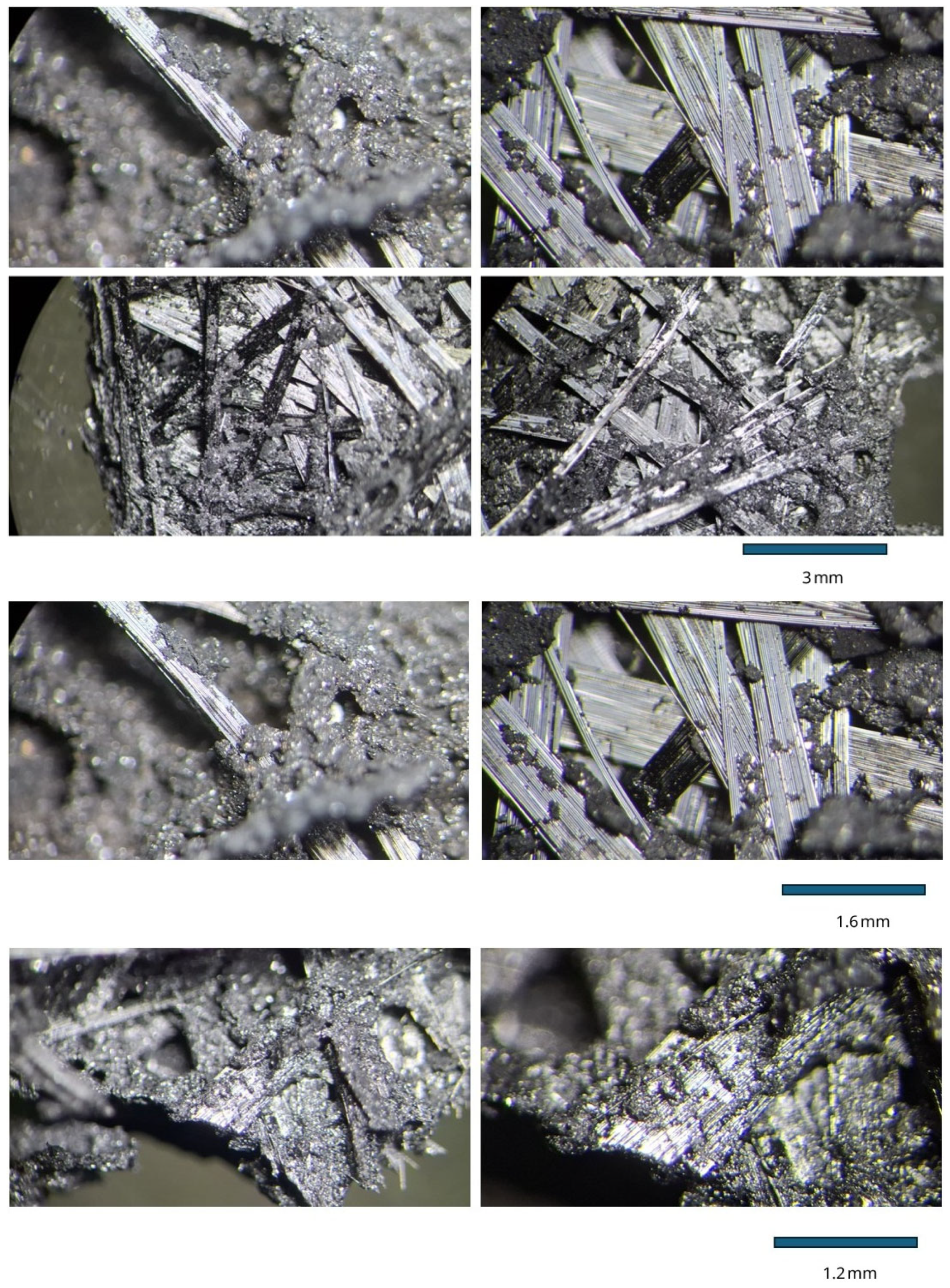
Microscopic observations using a stereoscopic microscope of the pyrolysis residue of the GFRP composite, conducted in three dimensions, revealed that the solid residue consists of two main components: glass fibers and a sintered carbonaceous material (char) originating from the thermal degradation of the polyester matrix. The char manifested as a black, glossy, porous mass enveloping the glass fibers and forming a cohesive structure. It was observed that the char filled the interstitial spaces between the fibers and effectively bonded the fibers together, which may significantly hinder their potential separation. Despite the presence of a dark coloration in the glass fibers, their morphological structure remained unaltered, indicating that the color change was attributable to a thin layer of char coating the fiber surface.
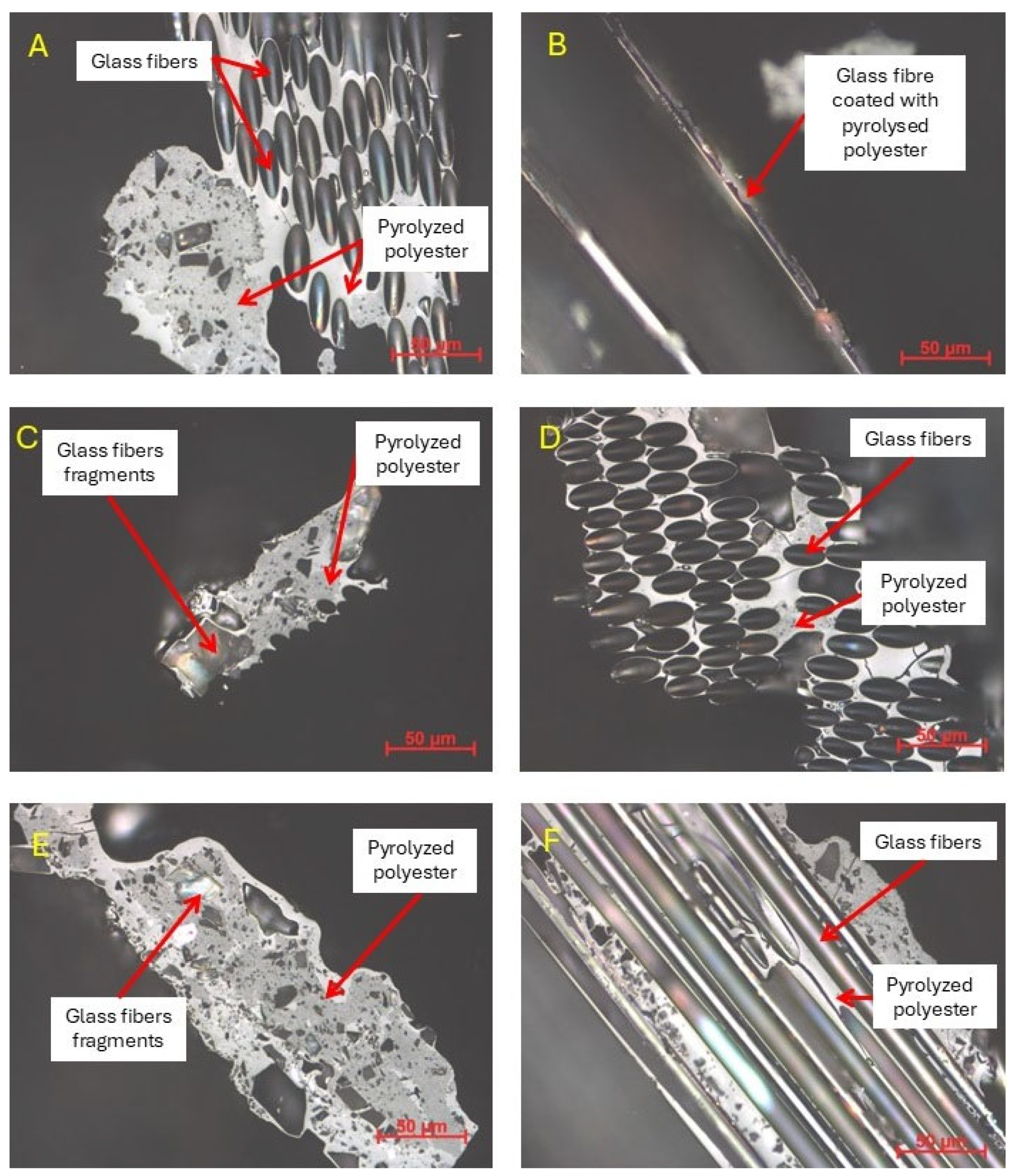
Detailed observations performed using an AxioImager M1m microscope in white light confirmed the presence of glass fibers and the surrounding char. The sintered carbonaceous mass exhibited low porosity and a compact character, indicating that the polymer material had softened during the pyrolysis process. The char matrix manifested predominantly isotropic characteristics, though localized regions of pronounced anisotropy were also identified. In certain regions, small fragments of broken glass fibers were discernible within the char mass, suggesting partial mechanical degradation of the composite during the processing stage. The recovery of clean fibers may require additional mechanical or chemical post-treatment, the feasibility of which—both technical and economic—remains to be further evaluated. This is particularly important in applications where high fiber purity is required.
As illustrated in
Figure 14A,C, photomicrographs clearly demonstrate the robust binding of the glass fibers by the char, thereby further substantiating its function as a binder that emerges as a consequence of the pyrolytic degradation of the polymer. Observations from
Figure 14F substantiate that the apparent color change in the fibers is attributable to a thin coating of carbonaceous residue, while the fibers themselves retained their smoothness and transparency—features characteristic of undamaged glass.
Microscopic analysis revealed that the pyrolysis process preserves the structural integrity of the glass fibers; however, the sintered char forms a durable and compact sheath that binds them together. Consequently, the efficient recovery of clean glass fibers may be hindered, particularly in scenarios where the intended reuse involves applications requiring high purity. To effectively disassociate the glass fibers from the carbonaceous remains, it may be necessary to implement additional mechanical or chemical post-treatment of the pyrolysis residue. Potential methods include mechanical abrasion, solvent washing, or oxidation, which will be investigated in future research.
While the morphology of the fibers is largely preserved, the presence of residual char may limit their direct reuse without further processing. Consequently, a comprehensive evaluation of the recyclability of the fibers necessitates a consideration of the challenges associated with physical separation and the potential for surface contamination to impact the performance of the fibers in secondary applications.
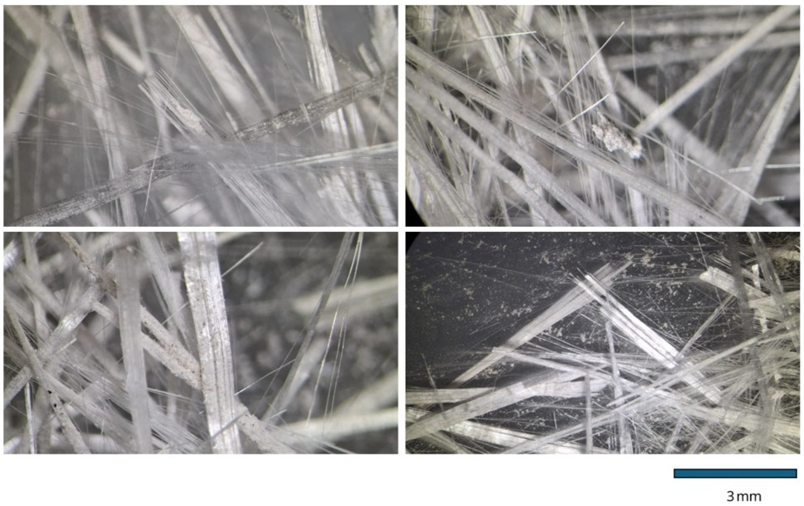
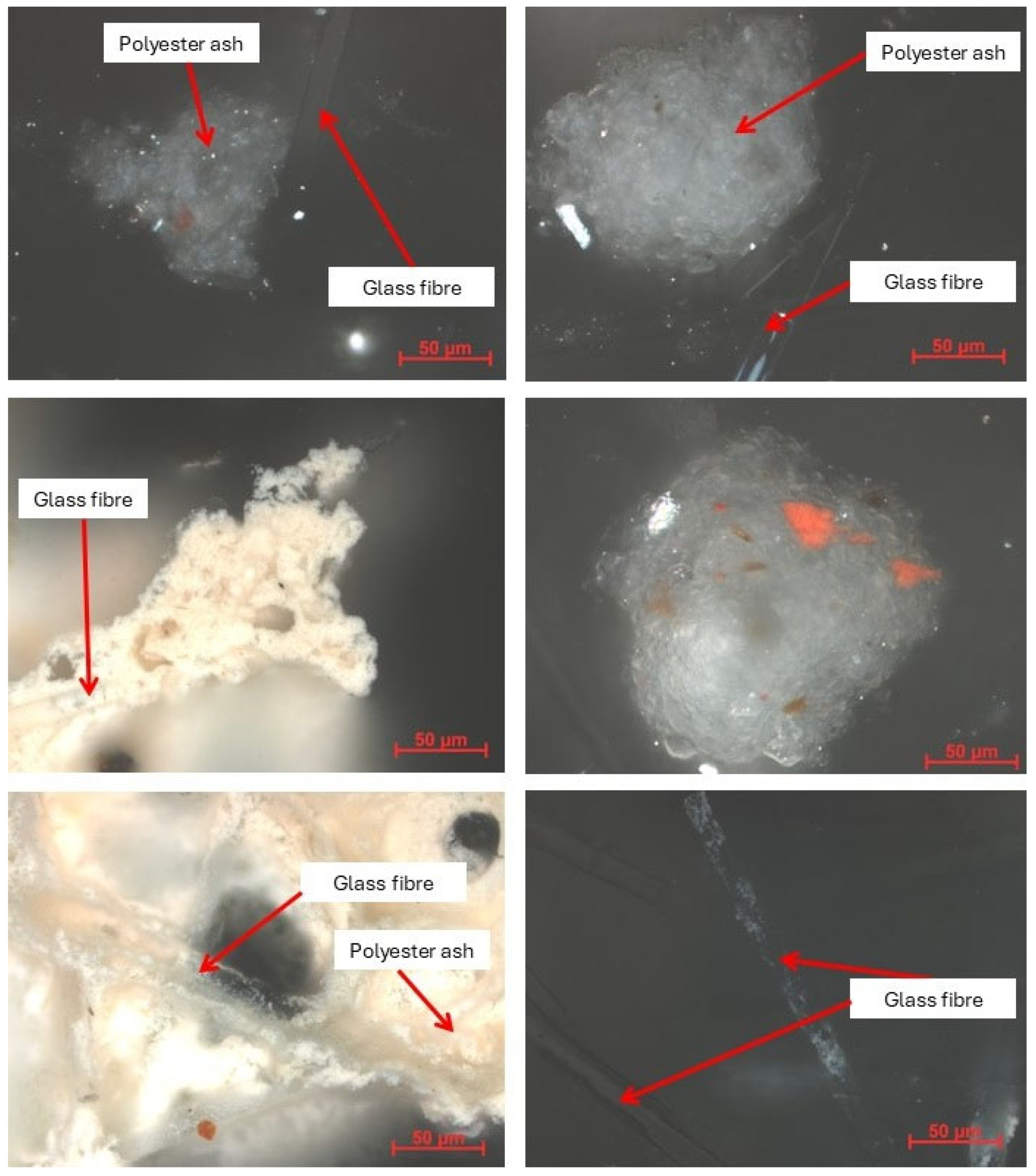
Microscopic analysis of the solid residue obtained from the combustion of a GFRP sample, performed using a stereoscopic microscope in three-dimensional mode, revealed the presence of two main components: fibrous glass fibers and fine particulate matter identified as ash. The white, finely grained ash was deposited on the surface of the glass fibers but did not cause any noticeable adhesion between them. The fibers, arranged in bundles, remained loose, and their structural integrity appeared to be preserved.
Subsequent observations employing a polarized microscope in white light substantiated the presence of ash particles and transparent glass fibers. The ash particles displayed morphological characteristics indicative of combustion residues derived from polymeric materials. It was found to be homogeneous, with minimal variation in color, suggesting a uniform origin for the combusted material. The ash exhibited a fine-grained or flake-like texture, with no discernible signs of sintering or bonding to the glass fibers. The fibers themselves were transparent, smooth, and predominantly free from internal defects.
The absence of binding between the ash and glass fibers suggests favorable conditions for their mechanical separation and potential recovery. From a structural standpoint, the glass fibers maintained their structural integrity and surface quality, which may prove advantageous in recycling processes. However, according to the literature [
23,
24,
25], exposure to high combustion temperatures (typically above 850 °C) may lead to a loss of mechanical strength of the glass fibers due to thermal degradation, surface devitrification, or the formation of microcracks.
Consequently, despite the fibers’ apparent morphological integrity, their actual potential for reuse, particularly in high-performance composite applications, may be constrained by thermally induced deterioration. Consequently, a comprehensive quality assessment of recovered fibers should encompass not only a morphological evaluation but also mechanical testing to verify their structural performance. For specific applications, such as fillers or low-load reinforcements, these thermally affected fibers may still be viable options. However, for critical structural components, additional validation is necessary.
In summary, the process of pyrolysis has been shown to preserve the structural and mechanical properties of the fibers to a certain extent. However, this process also leads to the adhesion of char, which complicates the direct recovery of the fibers. Conversely, combustion, while maintaining the physical separation of the fibers, can potentially compromise their mechanical strength through exposure to extreme temperatures. These disparate outcomes underscore the necessity for process-specific strategies to optimize fiber recovery and ascertain their viability for reuse.
To enhance the comparative clarity of the thermal recycling results, a summary table has been compiled below (
Table 3). It presents the key characteristics of each tested method—pyrolysis, gasification, and combustion – with respect to mass loss, solid residue yield, fiber morphology, ease of separation, and potential for reuse. This comparison supports a better understanding of the trade-offs involved in each thermal treatment process.
While this study focused on thermal recycling methods, it is worth noting—consistent with the general classification presented in
Figure 1—that chemical approaches such as solvolysis, as well as mechanical recycling, also present viable alternatives that merit further comparison in future research. Among chemical methods, solvolysis is particularly promising due to its ability to selectively depolymerize the resin matrix and recover clean fibers. However, in contrast to pyrolysis, solvolysis typically requires the use of specific solvents and precise reaction conditions, and presents challenges in terms of scalability and solvent recovery.
5. Conclusions
This work presents preliminary, single-trial results from an unfunded study aimed at identifying the most promising pathway for composite laminate waste treatment. While the findings provide a foundation for further in-depth investigation of recycling methods—including environmental and technical assessments—future research will include replicate measurements and statistical analysis to enhance the robustness and reliability of the results.
The research findings substantiate the considerable efficacy of polyester-glass laminates in reinforcing corroded steel fuel tanks, as evidenced by a nearly twofold reduction in stress levels within the structural shell. This contributes significantly to extending tank service life and reducing the environmental risk associated with potential leaks.
Thermogravimetric analysis of the waste GFRP composite revealed substantial potential for thermal treatment. Among the tested methods, pyrolysis emerged as the most promising, as it facilitates the recovery of intact glass fibers and the generation of valuable gaseous and liquid byproducts. Conversely, gasification yields only partial energy recovery with diminished fiber preservation, while combustion, while efficacious in reducing waste volume, completely destroys the glass fibers and generates substantial CO2 emissions.
Microscopic analysis of the residues confirmed that pyrolysis preserves the morphological structure of the glass fibers but results in their strong adhesion to a carbonaceous matrix (char), which complicates direct fiber recovery and may require additional mechanical or chemical cleaning processes. Conversely, combustion yields a fine ash that does not bind the fibers, leaving them physically loose and morphologically intact. However, it is important to note that the application of high temperatures, typically in excess of 850 °C, as reported in the extant literature, has been shown to potentially compromise the mechanical integrity of the recovered fibers. This decline in performance has been attributed to the occurrence of devitrification, microcracking, and a concomitant loss of strength.
Consequently, while both thermal processes may visually preserve fiber morphology, only pyrolysis offers the potential to maintain their mechanical integrity. The effective reuse of fibers necessitates not only an evaluation of their morphology but also mechanical testing and an assessment of surface quality.
Consequently, pyrolysis, as a method of waste polyester-glass laminate management, aligns optimally with the principles of the circular economy. This approach is substantiated by both environmental and technological justifications, particularly in the context of fuel tank waste.
Future research should focus on the following:
Optimizing pyrolysis parameters (temperature, atmosphere, residence time);
Scaling the process from applied research, through experimental development, to pilot-scale implementation;
Evaluating mechanical properties of recovered fibers for reuse;
Analyzing environmental impact and life cycle assessment (LCA) of the proposed recycling routes;
Developing methods for effective post-pyrolysis fiber cleaning and separation.
The development of such technologies has the potential to facilitate closed-loop management of composite materials and thereby contribute to a reduction in the environmental impact of the tank refurbishment industry.


 ,
, 


