Article

Direct Measurements of Petroleum Hydrocarbon Vapors in the Risk Assessment Procedure: The Case of a Contaminated Italian Site

by
Daniele Di Trapani
1,
Silvana Bifulco
2,
Marco Capodici
1,
Alida Cosenza
1,*,
Federica De Marines
1,
Marcello Farina
2,
Iason Verginelli
3 and
Gaspare Viviani
1
1
Dipartimento di Ingegneria, Università di Palermo, Viale delle Scienze, 90128 Palermo, Italy
2
ARPA Sicilia, Struttura Territoriale di Siracusa, Via Bufardeci, 22, 96100 Siracusa, Italy
3
Dipartimento di Ingegneria Civile e Ingegneria Informatica, Università degli Studi di Roma Tor Vergata, Via del Politecnico, 1, 00133 Roma, Italy
*
Author to whom correspondence should be addressed.
Sustainability 2025, 17(9), 4189; https://doi.org/10.3390/su17094189
Submission received: 12 March 2025 / Revised: 23 April 2025 / Accepted: 29 April 2025 / Published: 6 May 2025
(This article belongs to the Section Pollution Prevention, Mitigation and Sustainability)

Abstract

:
The direct measurement of volatile compounds is becoming increasingly important in assessing site contamination, particularly in relation to human health risk assessment and the design of remediation procedures. This study assesses the influence of direct measurements on the human health risk assessment conducted at a petroleum-contaminated site. Specifically, it provides contaminated-site risk managers with a quantitative comparison of the assessed risks by using measured and modeled data. A total of 16 monitoring campaigns were conducted at a Site of National Interest (SNI) located in Sicily (Italy), during which the hydrocarbon vapor concentrations in the subsurface soil porosity were measured using nested soil gas probes, while the related emitted fluxes were quantified with dynamic flux chambers. Measured data were compared with those obtained with a non-reactive diffusive model using the concentrations measured in the soil. The results highlighted significant overestimations of the expected outdoor concentrations obtained using non-reactive diffusive models by up to four orders of magnitude. These findings underscore the intrinsic limitation of non-reactive diffusive models, which provide overly conservative and unrealistic risk scenarios. Therefore, direct measurements might represent a cost-effective option to account for natural attenuation phenomena occurring in the subsurface, leading to a more realistic human health risk assessment (HHRA).

1. Introduction

The contamination of environmental matrices nowadays represents a major concern due to the potential risk to humans, water, ecosystems, and other receptors [1]. Soil pollution due to petroleum hydrocarbons is a challenging threat due to their mutagenic, carcinogenic, and toxic characteristics [2,3]. Their health impact depends on factors such as their chemical composition, the duration of exposure, and the route of contact. A major concern involves compounds such as benzene, toluene, ethylbenzene, and xylene—collectively known as BTEX—due to their toxicological significance. Acute exposure to volatile hydrocarbons may cause central nervous system depression, leading to symptoms such as headaches, dizziness, nausea, and in severe cases, unconsciousness. Skin contact often results in irritation or dermatitis, while ingestion may lead to internal organ damage or aspiration-induced chemical pneumonitis [4]. Chronic exposure has been linked to more severe health outcomes. Benzene is classified as a human carcinogen, with strong evidence associating it with bone marrow suppression and leukemia [5]. Chronic exposure to toluene and xylene has been shown to affect cognitive and motor functions, while other petroleum hydrocarbons are associated with liver and kidney damage, as well as reproductive and developmental toxicity. Moreover, polycyclic aromatic hydrocarbons (PAHs) have been linked to increased risks of lung, skin, and bladder cancers [6]. Children are particularly vulnerable due to developmental factors and behavior patterns. Prolonged exposure to hydrocarbons has been associated with neurodevelopmental delays, reproductive toxicity, and endocrine disruption [4].
For instance, Smith and coauthors [7] found that workers in petroleum refineries exhibited a markedly increased incidence of leukemia, with a mortality rate 15% greater than that observed in the general population. A recent study [8] reports that following the 2010 Deepwater Horizon disaster, high exposures to volatile components of crude oil were associated with deficits in the neurologic function among workers who were aged 50 years or older at the time of the study. Lv and coauthors [9] reported that benzene and o-xylene in blood were positively and statistically significantly associated with chronic obstructive pulmonary disease (COPD) prevalence. In more detail, as the concentration of blood benzene and blood o-xylene increased, the risk of COPD varied from 15.43% to 78.31% and from 2.99% to 3.49%, respectively.
The human health risk assessment (HHRA) procedure provides a quantitative assessment of the risks associated with the presence of contaminants in the subsurface and thus represents a useful tool to manage contaminated sites. Indeed, depending on the risk severity, the contaminated site might be subject to risk management measures consisting of remediation and/or safety actions. The Italian legislation regulating the reclamation of contaminated sites [10] assigns the status of “contaminated site” based on the assessment of the potential risks to human health and/or groundwater. The risk for human health derives from the application of HHRA carried out in accordance with the ASTM standard [11].
In this context, site investigation is of paramount importance, as it involves the collection of site-specific data and information on the contamination levels, pollutant migration pathways, and target exposure, thereby allowing for the development of an accurate Conceptual Site Model (CSM). Indeed, site heterogeneity, coupled with the complexity of the physical, chemical, and biological phenomena occurring in the environmental matrices, may hinder the realistic simulation of the pollutant transport to the targets. This aspect is of particular concern in cases of contamination by volatile organic compounds (VOCs), such as petroleum hydrocarbons, since the vapor transport assumes a major role for the assessment of the health risk for selected targets, particularly through inhalation [2,3].
In recent years, the transport of petroleum hydrocarbon vapors in the subsurface has been investigated in many studies, including field data collection campaigns [12,13,14,15] and modeling investigations [16,17,18,19,20,21,22].
In many cases, it has been demonstrated that the fate and transport models, usually applied in HHRA procedures, tend to overestimate the risks and provide overly conservative results that often do not represent the actual risk to which human targets are exposed [23]. Indeed, such models are generally non-reactive, and thus the occurrence of natural attenuation phenomena mainly related to biodegradation in the subsurface is not considered [15]. The usefulness of non-reactive diffusive models relies on the fact that they provide a basic, conservative, and simple estimate of how contaminants will move in the environmental matrices without undergoing chemical reactions. Although they do not consider complex chemical reactions, they offer a valuable initial step in evaluating the potential exposure or risk. Nevertheless, in cases of highly biodegradable compounds, they can lead to unrealistic values. Indeed, it has been shown that, compared to other VOCs that are poorly biodegradable (e.g., chlorinated hydrocarbons), petroleum hydrocarbons can be rapidly biodegraded in the subsurface under oxygen-rich conditions by ubiquitous hydrocarbon-degrading bacteria [23,24,25,26].
Several studies have highlighted that HHRAs based on VOC concentrations measured in the soil and/or groundwater can lead to an overestimation of the emission rates, sometimes by orders of magnitude, when compared with direct measurements [13,16,27]. These findings are mainly related to the fact that the aerobic biodegradation in vapor transport assessments is often neglected, despite the fact that several studies have confirmed the dominant role of biodegradation in controlling vapor-phase concentrations under oxygen-rich conditions. Research by Johnson et al. [28], Molins et al. [29], McHugh et al. [30], Lahvis et al. [13], and Hers et al. [14], among others, has consistently shown that petroleum vapor concentrations can be attenuated by several orders of magnitude within a few meters of vertical separation.
Therefore, direct measurements are gaining more attention in contaminated-site management procedures, both for HHRA as well as for the subsequent design of remediation measures [31]. In this context, relying on field-measured data is particularly crucial for verifying model-derived results, either in terms of the soil gas concentrations in the subsurface or the emitted fluxes at ground level.
Field measurements of soil gas fall into two broad categories: static measurements of gas concentrations, via a probe buried or inserted into the soil, and flux measurements of gas emissions from the soil surface, either by chambers enclosing an area of soil or by eddy-covariance towers [32]. While probe measurements can be used to generate a soil gas profile, chambers can be used to estimate the soil flux by observing the accumulation of gases inside the chamber over time. Both techniques can be used to obtain different insights; indeed, because the soil gas flux is a surface-specific measure, it can be used to determinate the soil emission factor that can be further extended to wider areas. Direct measures instead provide information on the soil gas presence in soil, but this is not directly related to soil emissions, the latter depending on local factors, such as soil capping or gas permeability. For further information on both detection methods, the reader is addressed to the literature [32,33,34,35].
In this light, the aim of the present study was to compare direct measurements of the soil gas and emission fluxes, obtained using nested soil gas probes [3] and dynamic flux chambers [36], with indirect estimates derived from non-reactive diffusive models based on soil concentration data.
Specifically, we present the results of 16 monitoring campaigns conducted in the area of a Site of National Interest (SNI) in Sicily (Italy), where the hydrocarbon vapor concentrations in the subsurface soil porosity were measured using nested soil gas probes, while the associated emitted fluxes were quantified with dynamic flux chambers. The measured data were then compared with those obtained from a non-reactive diffusive model to assess discrepancies in human health risk assessment.

2. Materials and Methods

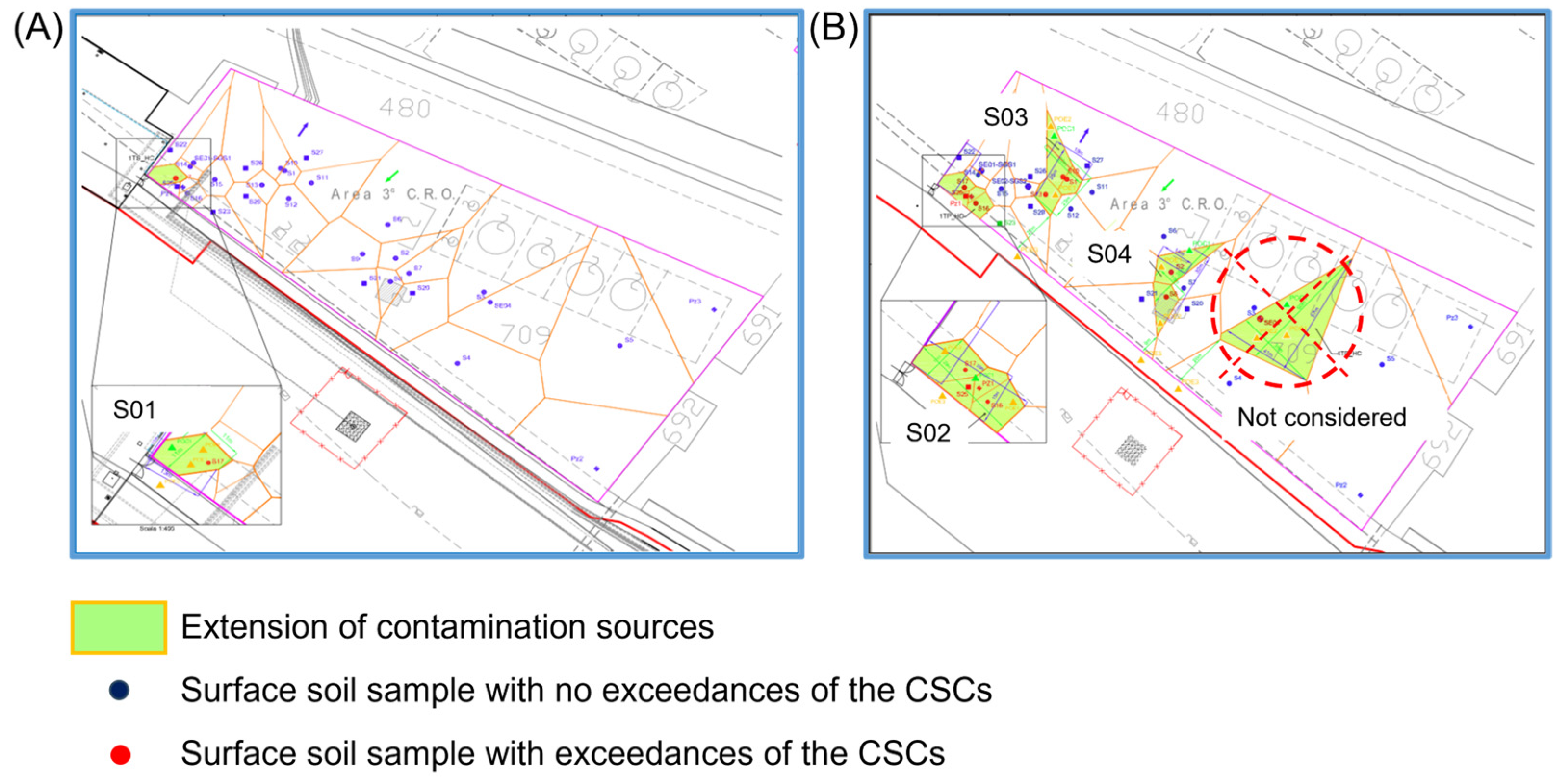
2.1. Case Study Description and Previous Activities

The case study (Figure 1) is characterized by an overall surface of 21.340 m2 that is mostly paved, except for some small green areas. The area belongs to a wider industrial area within a SNI located in Sicily (Italy). The area is still active and serves as a crude oil withdrawal and storage point, from which oil is transported to other collection points through dedicated pipelines.
The industrial activity carried out at the site during the last decades has produced the emissions of hazardous substances that have led to the need for urgent safety measures. These measures include the realization of hydraulic containment (using a pump and storage technique along with an on-site water treatment) combined with a soil–bentonite barrier wall to contain the transport of pollutants in the groundwater, thereby preventing their migration to the marine environment only a few meters away from the site.
An environmental site assessment was conducted in the case study area between November 2006 and January 2007, during which eight boreholes were realized, five reaching depths of 6 to 15 m below ground level and three extending to 30 m. The latter were also equipped as piezometers for groundwater sampling within the superficial aquifer, which is characterized by a water table depth of approximately 6.5 m below the ground level. In total, 56 soil samples and 3 groundwater samples were collected and analyzed for the requested contaminants. From the comparison with the screening levels of contamination, the potential human health risk associated with heavy petroleum hydrocarbons (C > 12) in the deep unsaturated soil was determined. Between 2013 and 2014, the area was subject to an integrative site assessment to delineate the extent of the contamination sources. As part of this investigation, 20 boreholes were further drilled, with the collection of 66 additional soil samples. The laboratory analyses revealed significant exceedances of the screening levels for light (C < 12) and heavy (C > 12) petroleum hydrocarbons, both in the surface and deep soil. Consequently, five potential contamination sources were identified, one in the surface soil and four in the deep soil.
The HHRA, performed by the company owner following the Risk-Based Corrective Action (RBCA) procedure [11], highlighted the absence of risks for human targets for all the contaminants investigated. Nevertheless, due to the presence of VOCs in the soil, it was decided to integrate the results achieved with direct measurements of the soil gas and emitted fluxes to validate the results obtained through the application of mathematical models used for risk assessment.

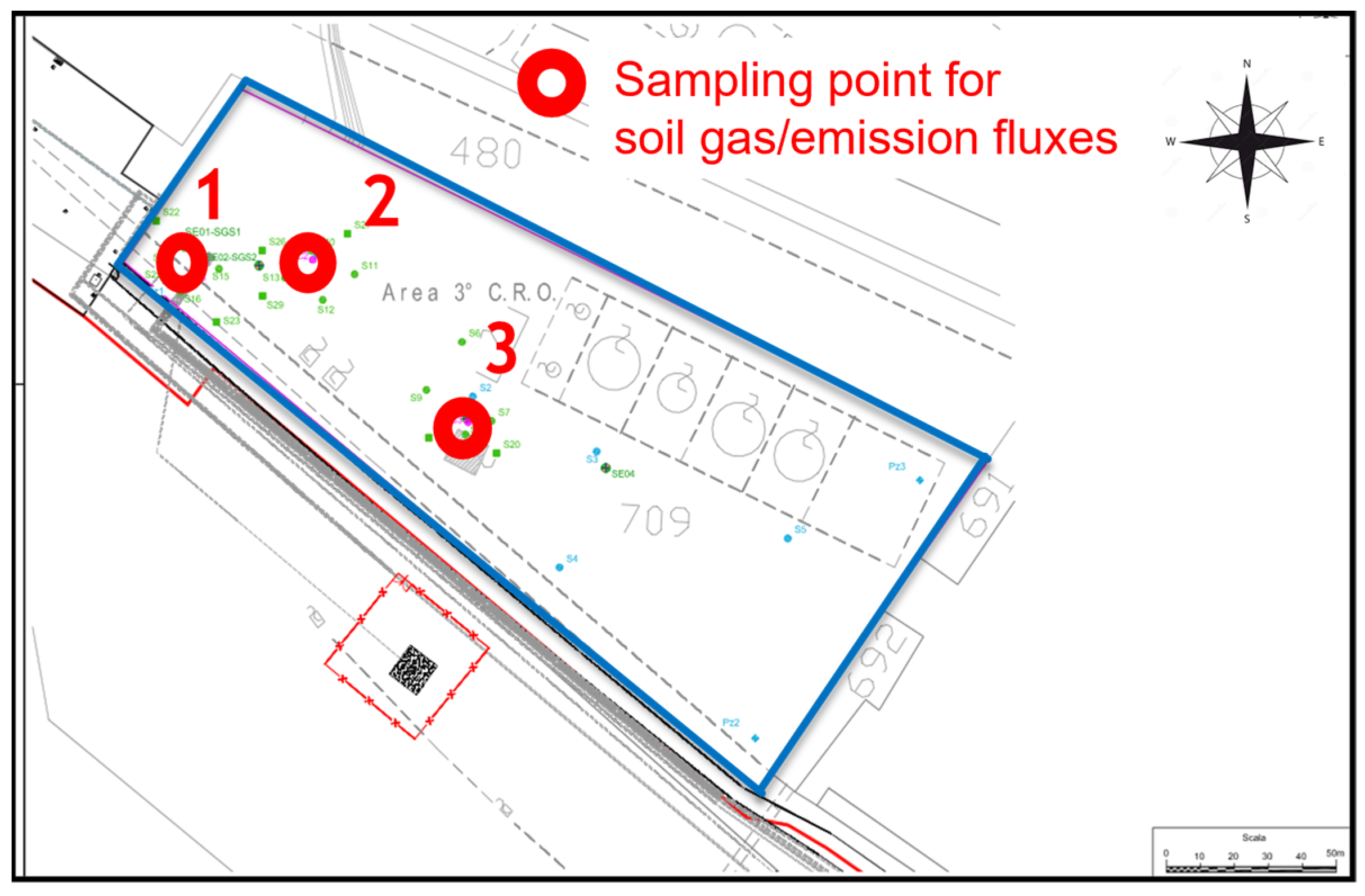
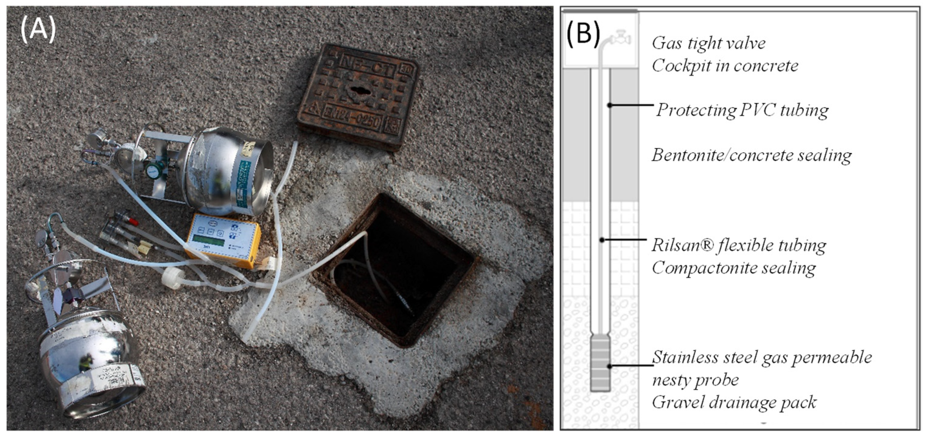
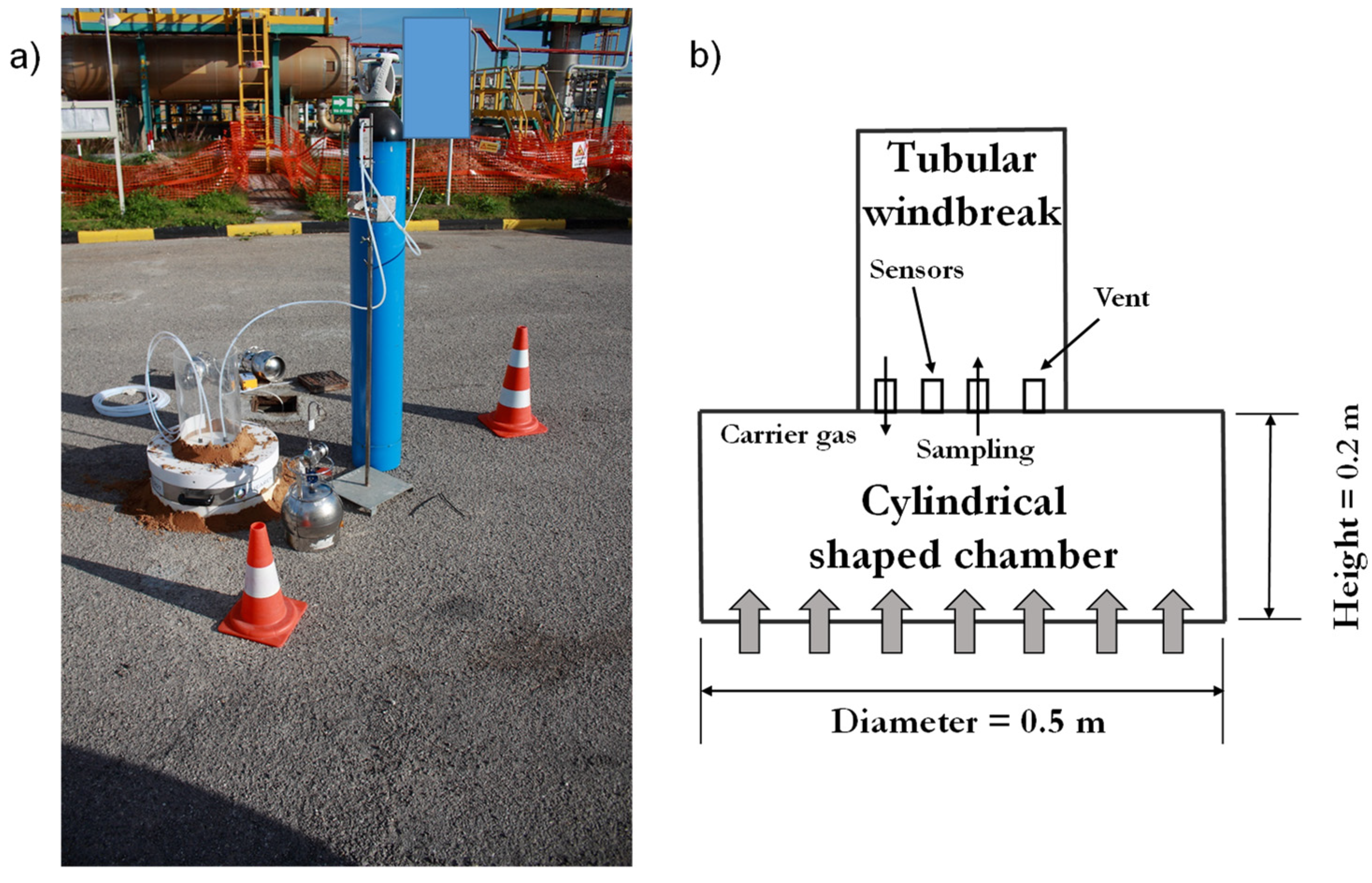
2.2. Experimental Campaign for Soil Gas and Emission Flux Measurements

The experimental design was developed by considering only four contamination sources, referred to as S01 (surface soil) and S02–S03–S04 (deep soil); this assumption was related to the position of the sampling points for the direct data measurement.
Figure 2 depicts the delineation of the contamination sources, showing both surface (Figure 2A) and deep soil (Figure 2B).
The monitoring grid was designed to cover the most critical areas identified in the previous site assessment, mostly based on the results of the hydrocarbon contamination found in the soil matrix. The selection of the monitoring points was decided in coordination with the control authority (Arpa Sicilia). The locations of the sampling points for the direct measurements are shown in Figure 3.
Regarding the soil gas measurements, three nested soil gas probes were used, characterized by a 30 cm length, a diameter ranging from 1/2” to 1”, and a detection threshold ranging between 1/10 and 1/100 ppb. The probes were positioned in the soil at depths ranging from 0.9 to 1.2 m below ground level. The borehole bottom was sealed by adding around 50 cm of sodium bentonite (referred to as camptonite, added in pellets) to prevent particulate suction. The hole portion surrounding the perforated part of the probe was filled with a gravel drain, while the upper part was sealed with a mixture of bentonite and concrete to minimize the suction of atmospheric gases through the soil during the sampling operations. The nested soil gas probes were connected to the surface with Rilsan® tubing and protected by a concrete cockpit. Figure 4 reports the details on the cockpit and the sampling equipment (Figure 4A), as well as a schematic layout of the nested soil gas probes (Figure 4B). Soil gas sampling was carried out with low-flow pumping (Figure 4A) with a maximum flow rate of 0.3 L min−1, continuously monitored through a gas flow meter. The collection of the soil gas samples was carried out using stainless-steel canisters that were previously calibrated in the laboratory by applying a vacuum level to ensure automatic gas sampling. Before sampling, it was waited for the re-equilibrium time after the purging operation to dissipate the pneumatic vacuum generated. Each sampling operation lasted almost 8 h.
The emission flux measures were carried out using a dynamic flux chamber [15,37] patented by Theolab s.r.l. The chamber consisted of a flat cylinder made of Teflon® with an inner diameter of 50 cm and a height of 20 cm. Due to the expected low fluxes, the use of a static chamber was not technically suitable, although it may be rather convenient during the screening phase. The flux chamber was equipped with a tubular-shaped windbreak positioned at the top of the box to minimize wind interference [38]. The inert gas carrier (high-purity nitrogen) was introduced within the chamber through a multi-hole helical tubing to guarantee complete mixing within the chamber. The gas carrier was introduced at a flow rate of 4.5 L/min, and to prevent the overpressurization of the chamber, an equivalent amount of the gas was allowed to escape through the vent present at the top of the chamber. To avoid air entering from the outside, the side wall of the chamber (both at the ground and at the windbreak system) were sealed with fine inert material (wet sand). The achievement of steady-state conditions was evaluated based on the stabilization of some parameters. In particular, the inside–outside differential pressure (measured with a portable pressure differential manometer), the internal temperature (measured with a digital thermometer with an insulated thermocouple probe), and the oxygen and carbon dioxide concentrations inside the chamber (measured with a portable real-time gas analyzer) were monitored through the dedicated ports. The sampling operation had a duration of 8 h. The use of a dynamic flux chamber was in accordance with the Italian guidelines [39]. Figure 5 shows a view of the adopted dynamic flux chamber (Figure 5a) together with a schematic layout (Figure 5b).
The gas samples collected in the field from soil gas probes and flux chambers were analyzed by GC-MS at a certified laboratory for benzene, aliphatics C5–C8, aliphatics C9–C12, aliphatics C13–C18, aliphatics C19–C36, aromatics C9–C10, aromatics C11–C12, and aromatics C13–C22, according to the following methods: EPA 5021A 2014 + EPA 8260 C 2006 and EPA 3550 C 2007 + EPA 8270 D 2014 for the aromatic fractions [40,41,42,43], and EPA 5021A 2014 + EPA 3550 C 2007 + EPA 8015 D 2003 and ISO 16703:2004 for the aliphatic fractions [40,41,44,45].
The direct gas measurements at the 3 monitoring locations were conducted during 16 sampling campaigns from February to December 2018 to evaluate both the daily and seasonal variability.

2.3. Human Health Risk Assessment—HHRA

The HHRA was conducted using the Risk-net 3.2 toolkit, developed by RECONnet (Italian Network on the Management and Remediation of Contaminated Sites) [46]. The software follows a procedure aligned with the Risk-Based Corrective Action (RBCA) framework [11].
Risk-net enables the calculation of human health risks based on measured data from soil and groundwater, applying the transport models specified in the ASTM standard. Additionally, it incorporates data from direct measurements in soil gas or flux chambers. In this work, to calculate the risks associated with the outdoor vapor inhalation pathway, industrial receptors were considered, applying the default exposure factors recommended in the Italian national guidelines [47]. Representative concentrations in the soil, soil gas, and flux chambers were determined based on the average values obtained from various monitoring activities at each sampling point. The simulations assumed a sandy soil with an organic carbon fraction of 0.001 g/g in the subsurface. The source dimension was set to 50 m. For the other input parameters required in the fate and transport models, the default values suggested by the Italian national guidelines [47] were used.
In view of quantifying the performance of the model compared to the measured data, the Root Mean Square Error (NRMSE) was quantified according to Equation (1):
R M S E = i = 1 N ( Y i Y ^ i ) 2 N
where Y i and Y ^ i represent the predicted and measured values of the ith analyte, and N is the total number of measured data points.

3. Results

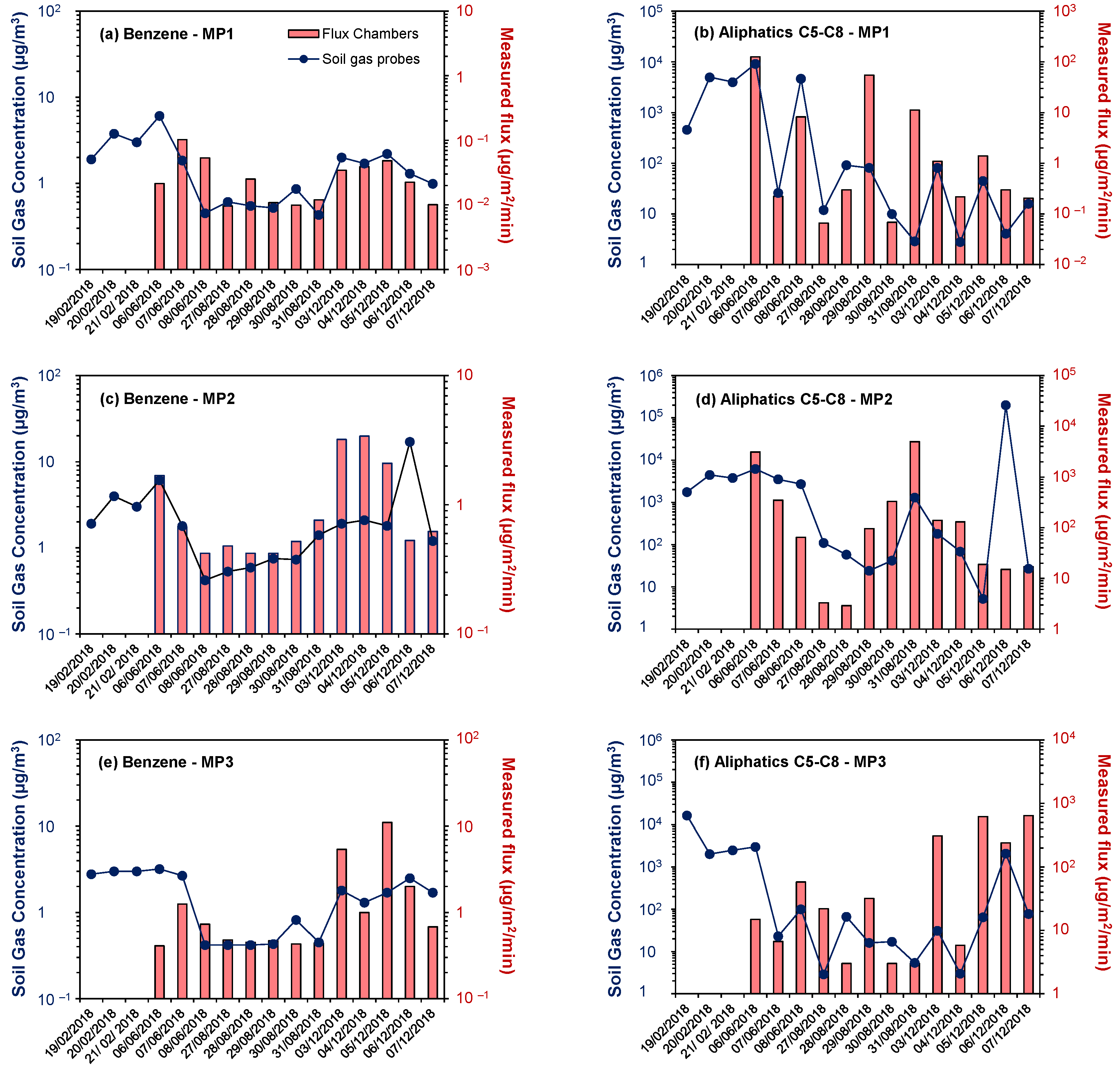
3.1. Comparison Between Soil Gas and Flux Chamber Data

Figure 6 shows the soil gas concentrations and fluxes measured at the three monitoring points (MPs) during the 16 measurement campaigns using the soil gas probes (blue dots, left y-axis) and flux chambers (red histograms, right y-axis). For illustrative purposes, only benzene and aliphatics C5–C8 are shown in the figures, as they represent the only compounds that were above the detection limit (DL) in almost all the campaigns. The other hydrocarbon fractions analyzed, particularly the heavier ones (aliphatics C19–C36 and aromatics C13–C22), were, in nearly all cases, below the detection limit.
The data in Figure 6 show that the soil gas concentrations (blue dots) are, on average, greater by one or two orders of magnitude than the vapor fluxes (red bars) both for benzene and aliphatics C5–C8.

3.2. Comparison Between Model and Field Data

Figure 7 compares the concentrations and fluxes measured using the nested soil gas probes (Figure 7a) and flux chambers (Figure 7b) at the three monitoring points across the different campaigns with the values predicted by the fate and transport models, based on the soil concentrations detected in the areas where direct measurements were conducted.
Benzene was excluded from this comparison, as its concentration in the soil was below the detection limit. Similarly, heavier hydrocarbons (i.e., aliphatics C19–C36 and aromatics C13–C22) are not shown in the graphs, as they were below the detection limit in all the campaigns. In the graphs reported in Figure 7, the diagonal black line represents a 1:1 linear correlation, indicating the condition in which the model predictions matched the direct measurements. Data that fall above the solid, black 1:1 line indicate cases where the modeled concentrations or fluxes were higher than the values measured in the field, meaning that the model tended to overestimate the actual observations. As a reference, the dashed lines represent scenarios where the modeled values were significantly higher than those measured. Specifically, the 1:100 line corresponds to modeled values 100 times greater than the measured ones, while the 1:10,000 line indicates cases where the model overestimated the field measurements by a factor of 10,000. These reference lines help to assess the extent of the overestimation.
The quantified RMSE values confirm that there is a great discrepancy between the modeled and measured data for all the analytes taken into account, especially for the flux data. Indeed, by comparing the modeled and measured data of the soil gas, the RMSE ranged between 1.24 × 10³ and 6.46 × 10⁸ for the aliphatics C5–C8 and the aromatics C13–C22, respectively. Moreover, by comparing the modeled and measured data of the fluxes, the RMSE ranged between 9.11 × 10⁻¹ and 9.67 × 10³ for the aliphatics C5–C8 and the aromatics C13–C22, respectively.

3.3. Role of Direct Measures in Human Health Risk Assessment

Table 1 reports the cumulative hazard index (HI) values related to the on-site outdoor inhalation of vapors calculated with the software Risk-net (version 3.1.1 pro) for the different classes of petroleum hydrocarbons measured in the soil (models), soil gas probes (SGSs), and flux chambers (FCs). For this estimation, the average concentration values detected at each monitoring point across the different campaigns were used. As a conservative estimate, the concentrations that were below the detection limit were assumed to be equal to the DL.

4. Discussion

From the data reported in Figure 6, it can be observed that both the soil gas concentrations and fluxes varied significantly across the different monitoring campaigns, with the differences spanning several orders of magnitude. These results highlight the extreme fluctuations in volatilization processes, even on a daily basis, as they might be strongly influenced by environmental conditions such as the barometric pressure, temperature, soil moisture, wind, and water table depth [48,49]. This aspect is of particular concern during the design phase of the experimental campaign [39]. Moreover, the comparison between the soil gas probe measurements and flux chamber data reveals that the trends in the flux and concentration changes do not always align across the campaigns. This discrepancy could be attributed to the different dynamics governing the emissions and soil gas concentrations. While soil gas concentrations are primarily influenced by subsurface humidity and temperature variations, emissions are also affected by pressure fluctuations at the soil–atmosphere interface [48]. Overall, these results highlight the importance of direct measurements in capturing subsurface vapor dynamics.
In the graphs reported in Figure 7, it is observed that nearly all the data points fall above the linear correlation line, suggesting that the standard fate and transport models, based on soil concentrations, overestimated the hydrocarbon concentrations and emission rates from the subsurface. Specifically, for soil gas probes, most of the data points lie above the 1:10,000 line, indicating that the model generally overestimated the soil gas concentrations by more than four orders of magnitude (Figure 7a). For the flux chambers (Figure 7b), most of the data points fall between the 1:100 and 1:10,000 lines, suggesting that the model typically overestimated the emission rates by two to four orders of magnitude. Similar findings have been reported in previous field studies, which have shown that in the case of petroleum hydrocarbons, the standard fate and transport models tend to overestimate soil gas concentrations and vapor fluxes by several orders of magnitude [15,50]. These overestimations are largely attributed to the fact that the standard models used in HHRA typically do not account for natural attenuation processes [50]. Among these, aerobic biodegradation in the unsaturated zone plays a particularly critical role. As discussed earlier, microorganisms capable of oxidizing petroleum hydrocarbon vapors to carbon dioxide, using molecular oxygen as electron acceptors, are widely distributed across a variety of subsurface environments [51,52]. Since aerobic biodegradation generally occurs at rates faster than those of physical vapor transport via diffusion or advection, it can lead to substantial reductions in vapor-phase hydrocarbon concentrations over relatively short vertical distances [3]. This phenomenon has been well documented in numerous field investigations, which consistently demonstrate the dominant role of biodegradation in controlling vapor-phase concentrations under oxygen-rich conditions. Studies by Lahvis et al. [53], Hers et al. [16], Roggemans et al. [54], Ririe et al. [55], Johnson et al. [28], Molins et al. [29], McHugh et al. [30], Lahvis et al. [13], and Hers et al. [14], among others, have shown that petroleum vapor concentrations can be attenuated by several orders of magnitude within just a few meters of vertical separation. These findings are consistent across a variety of hydrogeological settings and climatic conditions, emphasizing the importance of including biodegradation in vapor transport assessments.
From Table 1, it can be observed that the cumulative hazard index (HI) values achieved with direct measurements are always lower (from two to four orders of magnitude) compared to those derived from the fate and transport models based on the concentrations detected in the soil. Such results reflect the limited reliability of the standard fate and transport models to predict the behavior of petroleum vapors in the subsurface (see Figure 7), leading to overly conservative risk estimates for the volatilization pathway. This highly conservative approach may lead to unrealistic risk estimates, potentially affecting decisions on remediation or risk mitigation measures. The results of the present study in terms of the HI confirm the usefulness of direct measurements in the risk assessment, which can lead to a more realistic risk scenario, thereby providing a useful support for the final decision by authorities.

5. Conclusions

In this study, human health risks associated with a petroleum hydrocarbon-contaminated site were assessed using direct measurements of both the soil gas concentrations and emission flux rates, as well as modeled data based on soil measurements. The results highlighted a significant overestimation of the human health risks (up to four orders of magnitude) when using modeled data compared to those obtained by using direct measurements of the subsurface soil gas and/or emission rates. These overestimations were attributed to the use of simple diffusive, non-reactive models in the standard HHRA procedure, which do not account for hydrocarbon biodegradation in the subsurface. Consequently, risk scenarios may be overly conservative and not fully representative of the actual site conditions.
Overall, the findings of this study underscore the value of incorporating direct vapor emission measurements into risk assessments at petroleum hydrocarbon-contaminated sites. This approach addresses the key limitations of conservative modeling techniques and offers a more accurate and site-specific understanding of the exposure potential. From a regulatory and operational standpoint, the results support a broader adoption of direct measurement-based HHRAs in site investigations, particularly in cases where conventional models may lead to overestimated risks and potentially unnecessary remediation actions.
Looking ahead, future research should aim to improve both the measurement protocols and modeling approaches. In particular, the development and application of less conservative models that explicitly incorporate natural attenuation processes, such as aerobic biodegradation, could significantly enhance the accuracy of HHRAs. These models would provide a more realistic representation of the subsurface petroleum vapor behavior, especially under oxygen-rich conditions, where biodegradation is known to be effective.
Additionally, future efforts should also focus on establishing standardized guidelines for the use of direct measurements in regulatory contexts, enabling more balanced and evidence-based decision making in environmental risk management.

Author Contributions

Conceptualization, G.V., D.D.T., and M.F.; methodology, M.F., S.B., G.V., and D.D.T.; validation, I.V., F.D.M., D.D.T., and G.V.; formal analysis, A.C., M.C., and D.D.T.; investigation, A.C., D.D.T., M.F., and S.B.; resources, D.D.T., M.F., and G.V.; data curation, D.D.T., G.V., A.C., F.D.M., and I.V.; writing—original draft preparation, D.D.T., A.C., and M.C.; writing—review and editing, I.V. and F.D.M.; visualization, G.V., M.F., and S.B.; supervision, D.D.T. and G.V.; project administration, D.D.T., G.V., and M.F.; funding acquisition, D.D.T. and G.V. All authors have read and agreed to the published version of the manuscript.

Funding

This research was funded by the European Union NextGenerationEU, grant number “D.D. 1243 2/8/2022, PE0000005”.

Institutional Review Board Statement

Not applicable.

Informed Consent Statement

Not applicable.

Data Availability Statement

Data will be made available on request.

Acknowledgments

Part of this this study was carried out within the RETURN Extended Partnership and received funding from the European Union NextGenerationEU (National Recovery and Resilience Plan—NRRP, Mission 4, Component 2, Investment 1.3—D.D. 1243 2/8/2022, PE0000005). The authors sincerely thank Eng. Salvatore Di Pisa and Eng. Alessia Avona for their precious contributions during the initial data processing and health risk assessment.

Conflicts of Interest

The authors declare no conflicts of interest.

Abbreviations

The following abbreviations are used in this manuscript:
HHRAHuman Health Risk Assessment
CSMConceptual Site Model
VOCsVolatile Organic Compounds
RBCARisk-Based Corrective Action
MPMonitoring Point
DLDetection Limit
HIHazard Index
SGSSoil Gas Probe
FCFlux Chamber

References

  1. Islam, M.N.; Jung, S.K.; Jung, H.-Y.; Park, J.-H. The feasibility of recovering oil from contaminatedsoil at petroleum oil spill site using a subcriticalwater extraction technology. Process Saf. Environ. Prot. 2017, 111, 52–59. [Google Scholar] [CrossRef]
  2. ITRC. Petroleum Vapor Intrusion: Fundamentals of Screening, Investigation, and Management; Interstate Technology and Regulatory Council, Vapor Intrusion Team: Washington, DC, USA, 2014.
  3. U.S. EPA. Technical Guide for Addressing Petroleum Vapor Intrusion at Leaking Underground Storage Tank Sites; EPA 510-R-15-001; U.S. Environmental Protection Agency, Office of Underground Storage Tanks: Washington, DC, USA, 2015. Available online: http://www.epa.gov/oust/cat/pvi/pvi-guide-final-6-10-15.pdf (accessed on 7 December 2024).
  4. Agency for Toxic Substances and Disease Registry (ATSDR). Toxicological Profile for Total Petroleum Hydrocarbons (TPH); U.S. Department of Health and Human Services: Washington, DC, USA, 1999. Available online: https://www.atsdr.cdc.gov (accessed on 22 April 2025).
  5. International Agency for Research on Cancer (IARC). Benzene. IARC Monographs on the Evaluation of Carcinogenic Risks to Humans. 2018. Available online: https://monographs.iarc.who.int (accessed on 22 April 2025).
  6. World Health Organization (WHO). WHO Guidelines for Indoor Air Quality: Selected Pollutants. 2010. Available online: https://www.who.int/publications/i/item/9789289002134 (accessed on 22 April 2025).
  7. Smith, D.J.; Johnson, M.P.; Carter, H.R. Leukemia risk among petroleum refinery workers: A Cohort Study. Am. J. Ind. Med. 2022, 65, 567–579. [Google Scholar]
  8. Chen, D.; Werder, E.J.; Stewart, P.A.; Stenzel, M.R.; Gerr, F.E.; Lawrence, K.G.; Groth, C.P.; Huynh, T.B.; Ramachandran, G.; Banerjee, S.; et al. Exposure to volatile hydrocarbons and neurologic function among oil spill workers up to 6 years after the Deepwater Horizon disaster. Environ. Res. 2023, 231, 116069. [Google Scholar] [CrossRef] [PubMed]
  9. Lv, J.; Li, X.; Shen, Y.; You, J.; Wen, M.; Wang, J.; Yang, X. Assessing volatile organic compounds exposure and chronic obstructive pulmonary diseases in US adults. Front. Public Health 2023, 11, 1210136. [Google Scholar] [CrossRef]
  10. Legislative Decree N: 152/2006; Norme in materia ambientale (G.U. n. 88 14 aprile 2006). Istituto Poligrafico e Zecca dello Stato: Roma, Italy, 2006. (In Italian)
  11. ASTM. Standard Guide for Risk-Based Corrective Action, Designation: E-2081-00. 2000. Available online: https://store.astm.org/e2081-22.html (accessed on 28 April 2025).
  12. Davis, G.B.; Patterson, B.M.; Trefry, M.G. Evidence for instantaneous oxygen-limited biodegradation of petroleum hydrocarbon vapors in the subsurface. Groundw. Monit. Remediat. 2009, 29, 126–137. [Google Scholar] [CrossRef]
  13. Lahvis, M.A.; Hers, I.; Davis, R.V.; Wright, J.; DeVaull, G.E. Vapor intrusion screening at petroleum UST release sites. Groundw. Monit. Remediat. 2013, 33, 53–67. [Google Scholar] [CrossRef]
  14. Hers, I.; Jourabchi, P.; Lahvis, M.A.; Dahlen, P.; Luo, H.; Johnson, P.; DeVaull, G.E.; Mayer, K.U. Evaluation of seasonal factors on petroleum hydrocarbon vapor biodegradation and intrusion potential in a cold climate. Groundw. Monit. Remediat. 2014, 34, 60–78. [Google Scholar] [CrossRef]
  15. Verginelli, I.; Pecoraro, R.; Baciocchi, R. Using dynamic flux chambers to estimate the natural attenuation rates in the subsurface at petroleum contaminated sites. Sci. Total Environ. 2018, 619–620, 470–479. [Google Scholar] [CrossRef]
  16. Hers, I.; Atwater, J.; Li, L.; Zapf-Gilje, R. Evaluation of vadose zone biodegradation of BTX vapours. J. Contam. Hydrol. 2000, 46, 233–264. [Google Scholar] [CrossRef]
  17. DeVaull, G.E. Indoor vapor intrusion with oxygen-limited biodegradation for a subsurface gasoline source. Environ. Sci. Technol. 2007, 41, 3241–3248. [Google Scholar] [CrossRef]
  18. Verginelli, I.; Baciocchi, R. Vapor intrusion screening model for the evaluation of risk-based vertical exclusion distances at petroleum contaminated sites. Environ. Sci. Technol. 2014, 48, 13263–13272. [Google Scholar] [CrossRef] [PubMed]
  19. Yao, Y.; Wu, Y.; Wang, Y.; Verginelli, I.; Zeng, T.; Suuberg, E.M.; Jiang, L.; Wen, Y.; Ma, J. A petroleum vapor intrusion model involving upward advective soil gas flow due to methane generation. Environ. Sci. Technol. 2015, 49, 11577–11585. [Google Scholar] [CrossRef] [PubMed]
  20. Verginelli, I.; Capobianco, O.; Baciocchi, R. Role of the source to building lateral separation distance in petroleum vapor intrusion. J. Contam. Hydrol. 2016, 189, 58–67. [Google Scholar] [CrossRef]
  21. Yao, Y.; Verginelli, I.; Suuberg, E.M. A two-dimensional analytical model of petroleum vapor intrusion. Water Resour. Res. 2016, 52, 1528–1539. [Google Scholar] [CrossRef] [PubMed]
  22. Davis, G.B.; Knight, J.H.; Rayner, J.L. Extinguishing Petroleum Vapor Intrusion and Methane Risks for Slab-on-ground Buildings: A Simple Guide. Groundw. Monit. Remediat. 2021, 41, 61–72. [Google Scholar] [CrossRef]
  23. Ma, J.; Mchugh, T.; Beckley, L.; Lahvis, M.; Devaull, G.; Jiang, L. Vapor Intrusion Investigations and Decision-Making: A Critical Review. Environ. Sci. Technol. 2020, 54, 7050–7069. [Google Scholar] [CrossRef]
  24. Bekele, D.N.; Naidu, R.; Bowman, M.; Chadalavada, S. Vapor intrusion models for petroleum and chlorinated volatile organic compounds: Opportunities for Future Improvements. Vadose Zone J. 2013, 12, vzj2012.0048. [Google Scholar] [CrossRef]
  25. Almansoory, A.F.; Hasan, H.A.; Sheikh Abdullah, S.R.; Idris, M.; Anuar, N.; Al-Adiwish, W.M. Biosurfactant produced by the hydrocarbon-degrading bacteria: Characterization, Activity and Applications in Removing TPH from Contaminated Soil. Environ. Technol. Innov. 2019, 14, 100347. [Google Scholar] [CrossRef]
  26. Verginelli, I.; Lahvis, M.A.; Jourabchi, P.; DeVaull, G.E. Soil gas gradient method for estimating natural source zone depletion rates of LNAPL and specific chemicals of concern. Water Res. 2024, 267, 122559. [Google Scholar] [CrossRef]
  27. Lundegard, P.D.; Johnson, P.C. Source zone natural attenuation at petroleum hydrocarbon spill sites—II: Application to a Former Oil Field. Groundw. Monit. Remediat. 2006, 26, 93–106. [Google Scholar] [CrossRef]
  28. Johnson, P.C.; Lundegard, P.D.; Liu, Z. Source zone natural attenuation at petroleum hydrocarbon spill sites—I: Site-Specific Assessment Approach. Groundw. Monit. Remediat. 2006, 26, 82–92. [Google Scholar] [CrossRef]
  29. Molins, S.; Mayer, K.U.; Amos, R.T.; Bekins, B.A. Vadose zone attenuation of organic compounds at a crude oil spill site—Interactions Between Biogeochemical Reactions and Multicomponent Gas Transport. J. Contam. Hydrol. 2010, 112, 15–29. [Google Scholar] [CrossRef]
  30. McHugh, T.; Davis, R.; DeVaull, G.; Hopkins, H.; Menatti, J.; Peargin, T. Evaluation of vapor attenuation at petroleum hydrocarbon sites: Considerations for Site Screening and Investigation. Soil Sediment Contam. 2010, 19, 725–745. [Google Scholar] [CrossRef]
  31. Vecchio, A. Le linee guida sul monitoraggio degli aeriformi prodotte dal gruppo di lavoro 9 bis del SNPA. In Siti Contaminati: Esperienze Negli Interventi Di Risanamento; CSISA: Catania, Italy, 2019; pp. 65–79. (In Italian) [Google Scholar]
  32. Brummell, M.E.; Siciliano, S.D. Chapter Five—Measurement of Carbon Dioxide, Methane, Nitrous oxide, and Water Potential in Soil Ecosystems. Methods Enzymol. 2011, 496, 115–137. [Google Scholar] [CrossRef] [PubMed]
  33. Davidson, E.A.; Savage, K.; Verchot, L.V.; Navarro, R. Minimizing artifacts and biases in chamber-based measurements of soil respiration. Agric. For. Meteorol. 2002, 113, 21–37. [Google Scholar] [CrossRef]
  34. Grøndahl, L.; Friborg, T.; Christensen, T.R.; Ekberg, A.; Elberling, B.; Illeris, L.; Nordstrøm, C.; Rennermalm, Å.; Sigsgaard, C.; Søgaard, H. Spatial and Inter-Annual Variability of Trace Gas Fluxes in a Heterogeneous High-Arctic Landscape. Adv. Ecol. Res. 2008, 40, 473–498. [Google Scholar] [CrossRef]
  35. Pumpanen, J.; Kolari, P.; Ilvesniemi, H.; Minkkinen, K.; Vesala, T.; Niinistö, S.; Lohila, A.; Larmola, T.; Morero, M.; Pihlatie, M.; et al. Comparison of different chamber techniques for measuring soil CO2 efflux. Agric. For. Meteorol. 2004, 123, 159–176. [Google Scholar] [CrossRef]
  36. Eklund, B. Practical guidance for flux chamber measurements of fugitive volatile organic emission rates. J. Air Waste Manag. Assoc. 1992, 42, 1583–1591. [Google Scholar] [CrossRef]
  37. Ma, J.; McHugh, T.; Eklund, B. Flux chamber measurements should play a more important role in contaminated site management. Environ. Sci. Technol. 2020, 54, 11645–11647. [Google Scholar] [CrossRef]
  38. Saponaro, S.; Sezenna, E.; Careghini, A.; Mastorgio, A.; Spinelli, L. Open Dynamic Flux Chamber. Patent Application No. 0001427937, 29 March 2017. [Google Scholar]
  39. SNPA. Progettazione del monitoraggio dei vapori nei siti contaminati; Linea Guida SNPA 15/2018; SNPA: Roma, Italy, 2018; ISBN 978-88-448-0922-5. (In Italian) [Google Scholar]
  40. U.S. EPA. Method 5021A—Volatile Organic Compounds in Various Sample Matrices Using Equilibrium Headspace Analysis (SW-846); U.S. EPA: Washington, DC, USA, 2014; pp. 1–31.
  41. U.S. EPA. Method 8260C—Volatile Organic Compounds by Gas Chromatography/Mass Spectrometry (GC/MS); U.S. EPA: Washington, DC, USA, 2006; pp. 1–92.
  42. U.S. EPA. Method 3550C—Ultrasonic Extraction; U.S. EPA: Washington, DC, USA, 2007; p. 245.
  43. U.S. EPA. Method 8270D—Semivolatile Organic Compounds by Gas Chromatography/Mass Spectrometry; U.S. EPA: Washington, DC, USA, 2014; pp. 6–72.
  44. U.S. EPA. Method 8015C—Nonhalogenated Organics Using GC/FID; U.S. EPA: Washington, DC, USA, 2003; pp. 1–37.
  45. ISO 16703:2004; Soil Quality—Determination of Content of Hydrocarbon in the Range C10 to C40 by Gas Chromatography. ISO: Geneva, Switzerland, 2004.
  46. Verginelli, I. Risk-Net User Guide; Version 3.2; Reconnet: Rome, Italy, 2024; Available online: www.reconnet.net (accessed on 19 November 2024).
  47. ISPRA. Methodological Criteria for Absolute Risk Analysis Application at Contaminated Sites. Italian Environmental Protection Agency and Technical Services. 2008. Available online: www.isprambiente.gov.it (accessed on 15 December 2024). (In Italian)
  48. Unnithan, A.; Bekele, D.; Chadalavada, S.; Naidu, R. Insights into vapour intrusion phenomena: Current Outlook and Preferential Pathway Scenario. Sci. Total Environ. 2021, 796, 148885. [Google Scholar] [CrossRef]
  49. Verginelli, I. Petroleum vapor intrusion. In Advances in the Characterisation and Remediation of Sites Contaminated with Petroleum Hydrocarbons; Springer International Publishing: Cham, Switzerland, 2023; pp. 139–169. [Google Scholar]
  50. Provoost, J.; Reijnders, L.; Swartjes, F.; Bronders, J.; Seuntjens, P.; Lijzen, J. Accuracy of seven vapour intrusion algorithms for VOC in groundwater. J. Soils Sediments 2009, 9, 62–73. [Google Scholar] [CrossRef]
  51. Flintoft, L. Boost for bacterial batteries. Nat. Rev. Microbiol. 2003, 1, 88. [Google Scholar] [CrossRef]
  52. Fuchs, G.; Boll, M.; Heider, J. Microbial degradation of aromatic compounds—From One Strategy to Four. Nat. Rev. Microbiol. 2011, 9, 803–816. [Google Scholar] [CrossRef] [PubMed]
  53. Lahvis, M.A.; Baehr, A.L.; Baker, R.J. Quantification of aerobic biodegradation and volatilization rates of gasoline hydrocarbons near the water table under natural attenuation conditions. Water Resour. Res. 1999, 35, 753–765. [Google Scholar] [CrossRef]
  54. Roggemans, S.; Bruce, C.L.; Johnson, P.C.; Johnson, R.L. Vadose zone natural attenuation of hydrocarbon vapors: An Empirical Assessment of Soil Gas Vertical Profile Data. API Soil Groundw. Res. Bull. 2001, 15, 1–12. [Google Scholar]
  55. Ririe, G.T.; Sweeney, R.E.; Daugherty, S.J. A comparison of hydrocarbon vapor attenuation in the field with predictions from vapor diffusion models. Soil Sediment Contam. Int. J. 2002, 11, 529–554. [Google Scholar] [CrossRef]
Figure 1. Panoramic view of the case study area.
Sustainability 17 04189 g001
Figure 2. Delimitation of the contamination sources in the (A) surface soil and (B) deep soil.
Sustainability 17 04189 g002
Figure 3. Positions of the sampling points for direct measurements.
Sustainability 17 04189 g003
Figure 4. Details of the cockpit and the sampling equipment (A) and schematic layout of the experimental installation (B).
Sustainability 17 04189 g004
Figure 5. Panoramic view (a) and schematic layout (b) of the dynamic flux chamber used during monitoring campaigns.
Sustainability 17 04189 g005
Figure 6. Time series of measured soil gas concentrations and vapor fluxes for benzene (left column) and aliphatics C5–C8 (right column) at three different monitoring points (MPs). Soil gas concentrations, measured using subsurface gas probes, are shown as blue dots and are plotted on the left y-axis. Vapor fluxes, measured using flux chambers at the ground surface, are represented by red bars and are plotted on the right y-axis. The x-axis indicates the sampling dates over the duration of the monitoring campaigns (March to July 2018).
Sustainability 17 04189 g006
Figure 7. Comparison of the concentrations and fluxes measured using nested soil gas probes (a) and flux chambers (b) at the three monitoring points across the different campaigns with the values predicted by the fate and transport models, based on soil concentrations detected in the areas where direct measurements were conducted. Data are categorized by compound groups: aliphatics C5–C8 (▲), C9–C12 (■), and C13–C18 (◆), and aromatics C9–C10 (●) and C11–C12 (✕). The 1:1 solid line denotes the condition for which the model provided results in line with the field measurements. Data that fall above the solid black 1:1 line indicate cases where the modeled concentrations or fluxes were higher than the values measured in the field.
Sustainability 17 04189 g007
Table 1. Cumulative hazard index (HI) values related to the on-site outdoor inhalation of vapors calculated with the software Risk-net for the different classes of petroleum hydrocarbons measured in the soil (models), soil gas probes (SGSs), and flux chambers (FCs).
SourceCumulative Hazard Index Values for Total Hydrocarbons (HI)
ModelSGSFC
S013.1 × 10−14.6 × 10−57.9 × 10−3
S023.2 × 10−12.3 × 10−48.1 × 10−3
S031.3 × 10−14.5 × 10−55.2 × 10−3
Disclaimer/Publisher’s Note: The statements, opinions and data contained in all publications are solely those of the individual author(s) and contributor(s) and not of MDPI and/or the editor(s). MDPI and/or the editor(s) disclaim responsibility for any injury to people or property resulting from any ideas, methods, instructions or products referred to in the content.

