
On the Technical, Economic, and Environmental Impact of Mobilized Thermal Energy Storage: A Case Study


Abstract
1. Introduction
2. Study Case
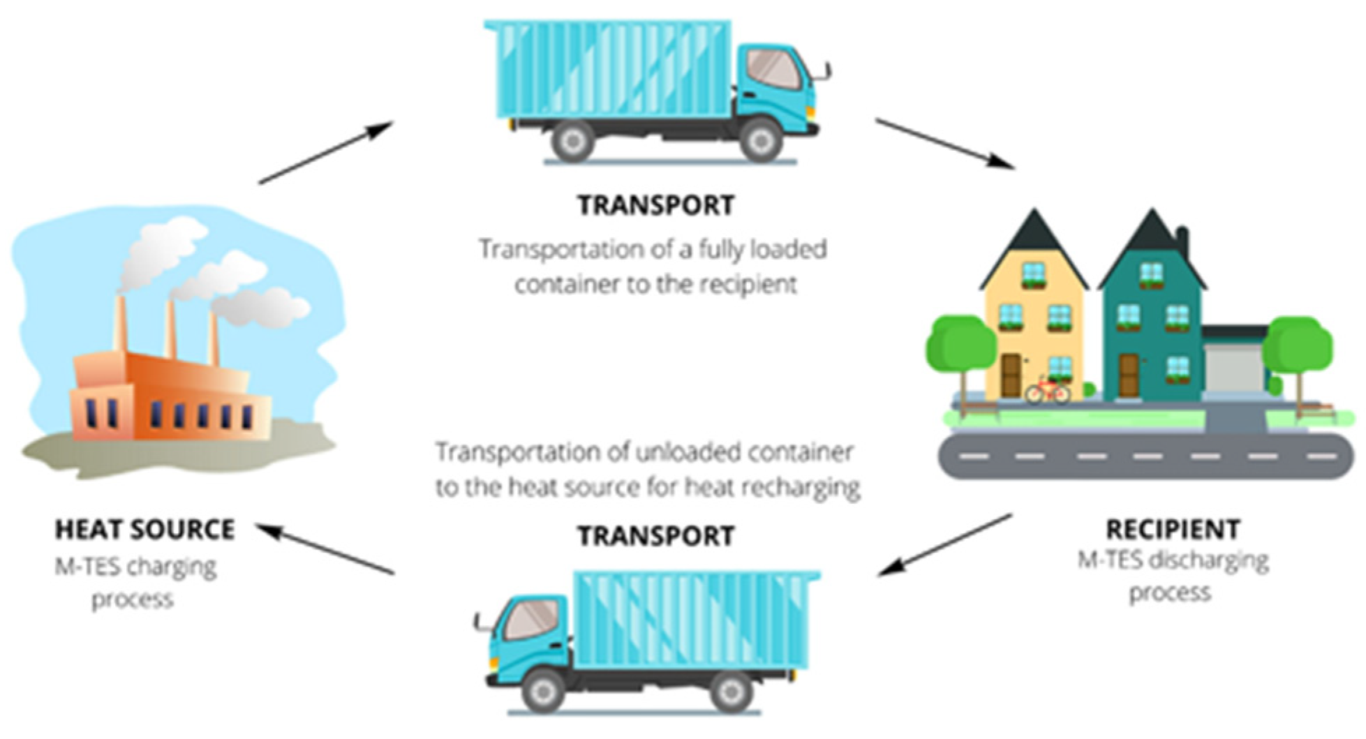
3. Components and Operation of the M-TES System
4. Adaptation to Current Heating Systems
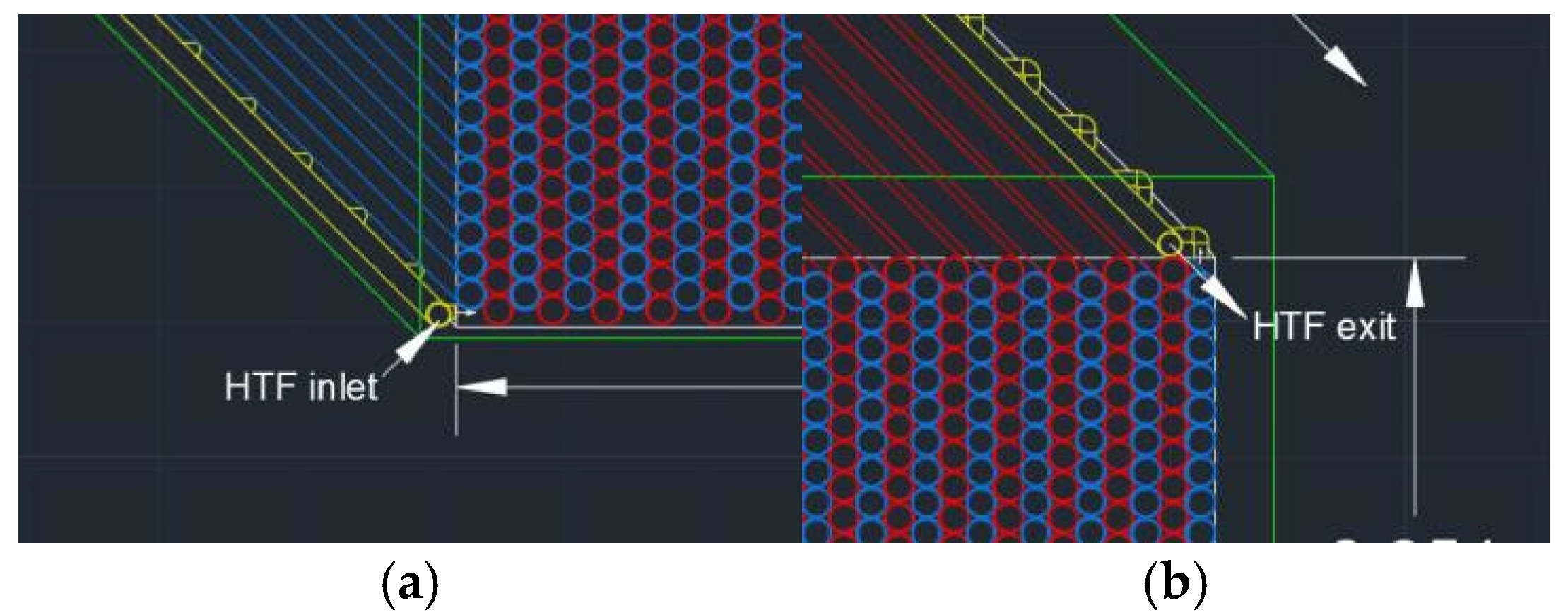
5. Operating Strategy and Container Design
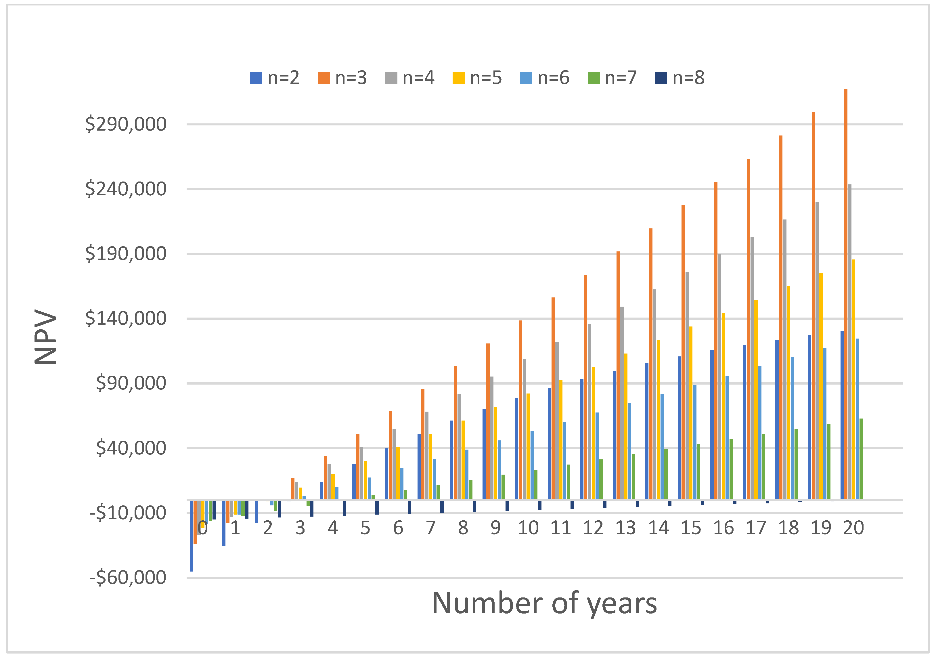
6. Economic Study

| Description | Unit Price [49] | n = 2 | n = 3 | n = 4 | n = 5 | n = 6 | n = 7 | n = 8 |
|---|---|---|---|---|---|---|---|---|
| Container | USD 2500 | USD 2500 | USD 2500 | USD 2500 | USD 2500 | USD 2500 | USD 2500 | USD 2500 |
| Erythritol | USD 3.50/kg | USD 38,666.70 | USD 25,777.80 | USD 19,555.60 | USD 15,466.70 | USD 12,888.90 | USD 11,047.60 | USD 10,133.30 |
| Aluminum tubes | USD 2/kg | USD 4606.60 | USD 3071.10 | USD 2329.80 | USD 1842.60 | USD 1535.50 | USD 1316.20 | USD 1207.20 |
| Therminol55 | USD 3/kg | USD 7466.70 | USD 4952.40 | USD 3733.30 | USD 2986.70 | USD 2514.30 | USD 2133.30 | USD 1981.00 |
| PRF | USD 1510/ton | USD 76.50 | USD 51.00 | USD 38.70 | USD 30.60 | USD 25.50 | USD 21.80 | USD 20.00 |
| Rockwool | USD 1/m2 | USD 24.70 | USD 16.50 | USD 12.50 | USD 9.90 | USD 8.20 | USD 7.10 | USD 6.50 |
| HX and pumps | USD 1.33/kWh | USD 1824.0 | USD 1216.00 | USD 912.00 | USD 729.60 | USD 608.00 | USD 521.10 | USD 456.00 |
| Sum | USD 55,165.10 | USD 37,584.70 | USD 29,081.80 | USD 23,566.00 | USD 20,080.40 | USD 17,547.20 | USD 16,304.00 | |
| Shipping (15%) | USD 8274.76 | USD 5637.70 | USD 4362.27 | USD 3534.91 | USD 3012.06 | USD 2632.08 | USD 2445.61 | |
| VAT (11%) | USD 910.22 | USD 620.15 | USD 479.85 | USD 388.84 | USD 331.33 | USD 289.53 | USD 269.02 | |
| Total cost | USD 64,350.10 | USD 43,842.50 | USD 33,923.90 | USD 27,489.80 | USD 23,423.80 | USD 20,468.80 | USD 19,018.70 | |
7. Environmental Assessment
8. Conclusions
Author Contributions
Funding
Institutional Review Board Statement
Informed Consent Statement
Data Availability Statement
Conflicts of Interest
References
- IEA. Key World Energy Statistics; International Energy Agency (IEA): Paris, France, 2016. [Google Scholar]
- Pérez-Lombard, L.; Ortiz, J.; Pout, C. A review on buildings energy consumption information. Energy Build. 2008, 40, 394–398. [Google Scholar] [CrossRef]
- Lahoud, C.; Chahwan, A.; Rishmany, J.; Yehia, C.; Daaboul, M. Enhancing Energy Efficiency in Mediterranean Coastal Buildings Through PCM Integration. Buildings 2024, 14, 4023. [Google Scholar] [CrossRef]
- IEA. World Energy Outlook; Organization for Economic Cooperation & Development: Paris, France, 2024. [Google Scholar]
- IEA and UN Environment Programme 2019 Global Status Report for Buildings and Construction. Available online: https://www.iea.org/reports/global-status-report-for-buildings-and-construction-2019 (accessed on 16 September 2024).
- Haselbach, L. The Engineering Guide to LEED-New Construction: Sustainable Construction for Engineers; McGraw-Hill: New York, NY, USA, 2010. [Google Scholar]
- EU Energy in Figures, Statistical Pocketbook 2018. Directorate General for Energy, European Commission. Available online: https://op.europa.eu/en/publication-detail/-/publication/99fc30eb-c06d-11e8-9893-01aa75ed71a1/language-en (accessed on 18 September 2024).
- Guo, S.P.; Zhao, J.; Wang, W.L.; Yan, J.Y.; Jin, G.; Zhang, Z.Y.; Gu, J.; Niu, Y.H. Numerical study of the improvement of an indirect contact mobilized thermal energy storage container. Appl. Energy 2016, 161, 476–486. [Google Scholar] [CrossRef]
- Guo, S.P.; Li, H.L.; Zhao, J.; Li, X.; Yan, J.Y. Numerical simulation study on optimizing charging process of the direct contact mobilized thermal energy storage. Appl. Energy 2013, 112, 1416–1423. [Google Scholar] [CrossRef]
- Wang, W.L.; Hu, Y.K.; Yan, J.Y.; Nyström, J.; Dahlquist, E. Combined heat and power plant integrated with mobilized thermal energy storage (M-TES) system. Front. Energy Power Eng. China 2010, 4, 469–474. [Google Scholar] [CrossRef]
- Kaizawa, A.; Kamano, H.; Kawai, A.; Jozuka, T.; Senda, T.; Maruoka, N.; Akiyama, T. Thermal and flow behaviors in heat transportation container using phase change material. Energy Convers. Manag. 2008, 49, 698–706. [Google Scholar] [CrossRef]
- Guo, S.; Zhao, J.; Bertrand, A.; Yan, J. Mobilized thermal energy storage for clean heating in carbon neutrality era: A perspective on policies in China. Energy Build. 2022, 277, 112537. [Google Scholar] [CrossRef]
- U.D.O. Energy. Energy Use, Loss and Opportunities Analysis: U.S. Manufacturing & Mining; Energetics Inc.: Columbia, MD, USA, 2004. [Google Scholar]
- Yabuki, Y.; Nagumo, T. Non-conduit Heat Distribution Using Waste Heat from a Sewage Sludge Incinerator. In Proceedings of the Water Environment Federation; Water Environment Federation: Alexandria, VA, USA, 2007; pp. 9306–9309. [Google Scholar]
- Kuta, M. Mobilized Thermal Energy Storage for Waste Heat Recovery and Utilization-Discussion on Crucial Technology Aspects. Energies 2022, 15, 8713. [Google Scholar] [CrossRef]
- Eid, S.; Brouche, M.; Lahoud, C.; Lahoud, C. Phase Change Materials Technologies Review and Future Application in Lebanon: Part II. Key Eng. Mater. 2021, 886, 256–270. [Google Scholar] [CrossRef]
- Eid, S.; Brouche, M.; Lahoud, C.; Lahoud, C. Phase Change Materials Technologies Review and Future Application in Lebanon: Part I. Key Eng. Mater. 2021, 886, 228–240. [Google Scholar] [CrossRef]
- Mehling, H.; Cabeza, L.F. Heat and Cold Storage with PCM: An Up to Date Introduction into Basics and Applications; Springer: New York, NY, USA, 2008. [Google Scholar]
- Du, K.; Calautit, J.; Wang, Z.; Wu, Y.; Liu, H. A review of the applications of phase change materials in cooling, heating and power generation in different temperature ranges. Appl. Energy 2018, 220, 242–273. [Google Scholar] [CrossRef]
- Wang, W.L.; Yan, J. Mobilized Thermal Energy Storage (M-TES) Technology for Industry Heat Recovery. In Handbook of Clean Energy Systems; Wiley: Hoboken, NJ, USA, 2015. [Google Scholar]
- Du, K.; Calautit, J.; Eames, P.; Wu, Y. A-state-of-the-art review of Phase Change Materials (PCM) in Mobilized- Thermal Energy Storage (M-TES) for recovering low-temperature Industrial Waste Heat (IWH) for distributed heat supply. Renew. Energy 2021, 168, 1040–1057. [Google Scholar] [CrossRef]
- Chiu, J.N.; Martin, V. Industrial surplus heat storage in smart cities. In Energy Sustainability; American Society of Mechanical Engineers: New York, NY, USA, 2015. [Google Scholar]
- Kaizawa, N.M.A.; Kawai, A.; Kamano, H.; Jozuka, T.; Senda, T.; Akiyama, T. Thermophysical and heat transfer properties of phase change material candidate for waste heat transportation system. Heat Mass Transf. 2008, 44, 763–769. [Google Scholar] [CrossRef]
- Kaizawa, A.; Kamano, H.; Kawai, A.; Jozuka, T.; Senda, T.; Maruoka, N.; Okinaka, N.; Akiyama, T. Technical Feasibility Study of Waste Heat Transportation System Using Phase Change Material from Industry to City. ISIJ Int. 2008, 48, 540–548. [Google Scholar] [CrossRef]
- Peiró, G.; Gasia, J.; Miró, L.; Cabeza, L.F. Experimental evaluation at pilot plant scale of multiple PCMs (cascaded) vs. single PCM configuration for thermal energy storage. Renew. Energy 2015, 83, 729–736. [Google Scholar] [CrossRef]
- Wang, Y.; Yu, K.; Ling, X. Experimental study on thermal performance of a mobilized thermal energy storage system: A case study of hydrated salt latent heat storage. Energy Build. 2020, 210, 109744. [Google Scholar] [CrossRef]
- Storch, G.; Hauer, A. Cost-effectiveness of a heat energy distribution system based on mobile storage units: Two case studies. In Proceedings of the ECOSTOCK Conference, Stockton, CA, USA, 31 May–2 June 2006. [Google Scholar]
- Deckert, M.; Scholz, R.; Binder, S.; Hornung, A. Economic efficiency of mobile latent heat storages. Energy Procedia 2014, 46, 171–177. [Google Scholar] [CrossRef]
- Chiu, J.N.; Castro Flores, J.; Martin, V.; Lacarrière, B. Industrial surplus heat transportation for use in district heating. Energy 2016, 110, 139–147. [Google Scholar] [CrossRef]
- Nagano, K.; Ogawa, K.; Mochida, T.; Hayashi, K.; Ogoshi, H. Thermal characteristics of magnesium nitrate hexahydrate and magnesium chloride hexahydrate mixture as a phase change material for effective utilization of urban waste heat. Appl. Therm. Eng. 2004, 24, 221–232. [Google Scholar] [CrossRef]
- Li, H.L.; Wang, W.L.; Yan, J.; Dahlquist, E. Economic assessment of the mobilized thermal energy storage (M-TES) system for distributed heat supply. Appl. Energy 2013, 104, 178–186. [Google Scholar] [CrossRef]
- Hester, R.E.; Harrison, R.M. Energy Storage Options and Their Environmental Effect; Royal Society of Chemistry: London, UK, 2019. [Google Scholar]
- Kakiuchi, H.; Yamazaki, M.; Yabe, M.; Chihara, S.; Terunuma, Y.; Sakata, Y.; Usami, T. A Study of Erythritol as Phase Change Material. In Proceedings of the IEA Annex 10—PCMs and Chemical Reactions for Thermal Energy Storage, 2nd Workshop, Sofia, Bulgaria, 11–13 November 1998. [Google Scholar]
- Thermal Standard for Buildings in Lebanon for New Residential and Non-Residential Buildings. 2010. Available online: https://docslib.org/doc/6393707/thermal-standard-for-buildings-in-lebanon-2010 (accessed on 18 September 2024).
- Matuszewska, D.; Kuta, M.; Olczak, P. Techno-Economic Assessment of Mobilized Thermal Energy Storage System Using Geothermal Source in Polish Conditions. Energies 2020, 13, 3404. [Google Scholar] [CrossRef]
- Lahoud, C.; Harake, R.; Fatfat, M.; Bazi, S. Enhancing Energy Efficiency in Mediterranean Large-Scale Buildings: A Study on Mobilized Thermal-Energy-Storage Systems. Buildings 2025, 15, 464. [Google Scholar] [CrossRef]
- Zhakiyev, N.; Sagadatova, N.; Ismagulova, G.; Bakdolotov, A.; Biloshchytskyi, A. Hybrid Technico-Economical Modeling of the Mid-Term Green Economy and Low-Carbon Development Strategy of Kazakhstan. ES Energy Environ. 2024, 25, 1235. [Google Scholar] [CrossRef]
- Yuan, M.; Ren, Y.; Xu, C.; Ye, F.; Du, X. Characterization and stability study of a form-stable erythritol/expanded graphite composite phase change material for thermal energy storage. Renew. Energy 2019, 136, 211–222. [Google Scholar] [CrossRef]
- Agyenim, F.; Eames, P.; Smyth, M. Experimental study on the melting and solidification behaviour of a medium temperature phase change storage material (Erythritol) system augmented with fins to power a LiBr/H2O absorption cooling system. Renew. Energy 2011, 36, 108–117. [Google Scholar] [CrossRef]
- Mawire, A.; Ekwomadu, C.; Lefenya, T.; Shobo, A. Performance comparison of two medium temperature packed bed latent heat storage systems during charging. In Proceedings of the ISES Solar World Congress, Santiago, Chile, 4–7 November 2019. [Google Scholar]
- Liu, M.; Saman, W.; Bruno, F. Review on storage materials and thermal performance enhancement techniques for high temperature phase change thermal storage systems. Renew. Sustain. Energy Rev. 2012, 16, 2118–2132. [Google Scholar] [CrossRef]
- Available online: www.therminol.com (accessed on 10 November 2024).
- Mourtada, A.; Hussein, K.; Hamadi, A.; Nakad, Z.; Ajouz, H. Parametric analysis for the Development of an Energy Building Code for Lebanon: HVAC Chapter. In Proceedings of the 2018 4th International Conference on Renewable Energies for Developing Countries (REDEC), Beirut, Lebanon, 1–2 November 2018; pp. 1–7. [Google Scholar] [CrossRef]
- Wang, W.L. Mobilized Thermal Energy Storage for Heat Recovery for Distributed Heating; Mälardalen University: Mälardalen, Sweden, 2010; ISBN 978-91-86135-98-0. [Google Scholar]
- Available online: www.Aluminum.org (accessed on 4 October 2024).
- Bergman, T.; Lavine, A.; Incropera, F.; Dewitt, D. Fundamentals of Heat and Mass Transfer, 8th ed.; John Wiley and Sons: Hoboken, NJ, USA, 2017. [Google Scholar]
- Yang, S.; Gao, H.O.; You, F. Demand flexibility and cost-saving potentials via smart building energy management: Opportunities in residential space heating across the US. Adv. Appl. Energy 2024, 14, 100171. [Google Scholar] [CrossRef]
- Available online: https://www.pelletheat.org/compare-fuel-costs (accessed on 2 December 2024).
- Yang, J.; Chen, W.C.; Chen, B.; Jia, Y. Economic feasibility analysis of a renewable energy project in the rural China. Procedia Env. Environ. Sci. 2012, 13, 2280–2283. [Google Scholar] [CrossRef]
- Blank, L.; Tarquin, A. Engineering Economy; McGraw-Hill: New York, NY, USA, 2006. [Google Scholar]
- Caresana, F.; Brandoni, C.; Feliciotti, P.; Bartolini, C.M. Energy and economic analysis of an ICE-based variable speed-operated micro-cogenerator. Appl. Energy 2011, 88, 659–671. [Google Scholar] [CrossRef]
- Hucho, W.H.; Sovran, G. Aerodynamics of road vehicles. Annu. Rev. Fluid Mech. 2003, 25, 485–537. [Google Scholar] [CrossRef]
- Kurtus, R. Coefficient of Rolling Friction. November 2016. Available online: https://www.school-for-champions.com/science/friction_resources.htm#Rolling (accessed on 2 December 2024).
- Bayandirli, C.; Erkan Akansu, Y.; Sahir Salman, M. The determination of aerodynamic drag coefficient of truck and trailer model by wind tunnel tests. Int. J. Automot. Eng. Technol. 2016, 5, 53–60. [Google Scholar]
- Wang, B.; Pamminger, M.; Wallner, T. Impact of fuel and engine operating conditions on efficiency of a heavy-duty truck engine running compression ignition mode using energy and exergy analysis. Appl. Energy 2019, 254, 113645. [Google Scholar] [CrossRef]
- Available online: https://energieplus-lesite.be/ (accessed on 5 December 2024).


| Item | T (°C) | Density (kg/m3) | Cp (kJ/kg·K) | Thermal Conductivity (W/m·K) | Latent Heat (kJ/kg) | Melting Point (°C) | Flash Point (°C) | Boiling Temperature (°C) | Viscosity (kg/(m·s)) | Dynamic Viscosity (MPa·s) |
|---|---|---|---|---|---|---|---|---|---|---|
| Erythritol (PCM) | 20 | 1480 | 1.35 | 0.732 | 339 | 118 | - | - | 0.02895 | - |
| 140 | 1300 | 2.74 | 0.326 | - | - | 0.01602 | - | |||
| Therminol55 (HTF) | 33 | 865 | 1.94 | 0.1273 | - | - | 177 | 351 | - | 25.2 |
| 130 | 797 | 2.3 | 0.1156 | - | - | - | 1.71 |
| Details | Data | ||||||
|---|---|---|---|---|---|---|---|
| n | 2 | 3 | 4 | 5 | 6 | 7 | 8 |
| Capacity (MWh) | 1.37 | 0.91 | 0.69 | 0.55 | 0.46 | 0.39 | 0.34 |
| Container volume (m3) | 10.55 | 7.03 | 5.27 | 4.22 | 3.52 | 3.01 | 2.64 |
| Container mass (t) | 16.16 | 10.77 | 8.15 | 6.46 | 5.41 | 4.62 | 4.10 |
| PCM (t) | 11.05 | 7.37 | 5.59 | 4.42 | 3.68 | 3.16 | 2.90 |
| Thermal oil (t) | 2.49 | 1.65 | 1.24 | 1.00 | 0.84 | 0.71 | 0.66 |
| PRF (t) | 0.051 | 0.034 | 0.026 | 0.02 | 0.017 | 0.014 | 0.013 |
| Rockwool(m2) | 24.72 | 16.48 | 12.5 | 9.89 | 8.24 | 7.06 | 6.48 |
| Pipes (t) | 2.30 | 1.54 | 1.16 | 0.92 | 0.77 | 0.66 | 0.60 |
| n | 2 | 3 | 4 | 5 | 6 | 7 | 8 |
|---|---|---|---|---|---|---|---|
| Empty truck (Actros 4846 K) (kg) | 11,268 | 11,268 | 11,268 | 11,268 | 11,268 | 11,268 | 11,268 |
| Container mass (kg) | 32,046 | 21,358 | 16,173 | 12,818 | 10,718 | 9156 | 8272 |
| Total mass (kg) | 43,314 | 32,626 | 27,441 | 24,086 | 21,986 | 20,424 | 19,540 |
| n | 2 | 3 | 4 | 5 | 6 | 7 | 8 |
|---|---|---|---|---|---|---|---|
| Fuel consumption per km | 0.292 | 0.228 | 0.197 | 0.177 | 0.164 | 0.155 | 0.150 |
| Truck yearly consumption | 1879.16 | 2200.79 | 2534.66 | 2845.08 | 3171.23 | 3489.03 | 3851.21 |
| Total volume of diesel saved | 17,320.84 | 16,999.21 | 16,665.34 | 16,354.92 | 16,028.77 | 15,710.97 | 15,348.79 |
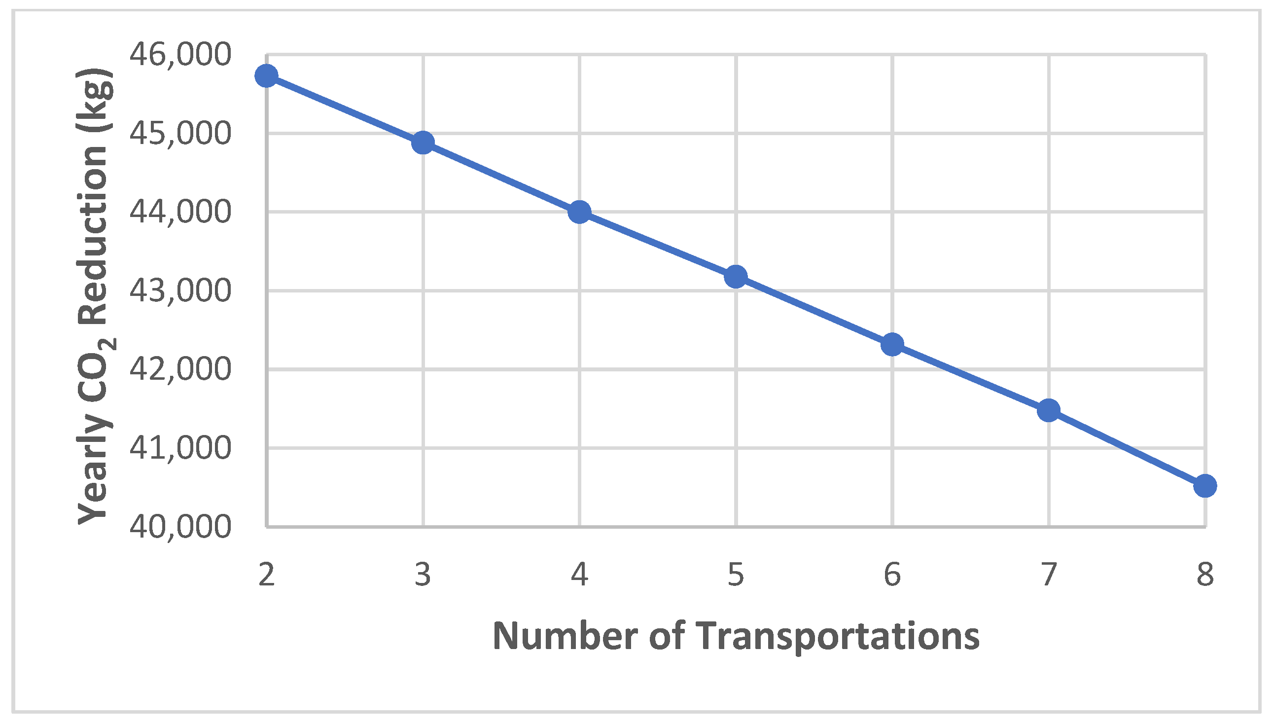
| Yearly CO2 reduction (kg) | 45,727.0 | 44,877.9 | 43,996.5 | 43,177.0 | 42,316.0 | 41,477.0 | 40,520.8 |
Disclaimer/Publisher’s Note: The statements, opinions and data contained in all publications are solely those of the individual author(s) and contributor(s) and not of MDPI and/or the editor(s). MDPI and/or the editor(s) disclaim responsibility for any injury to people or property resulting from any ideas, methods, instructions or products referred to in the content. |
© 2025 by the authors. Licensee MDPI, Basel, Switzerland. This article is an open access article distributed under the terms and conditions of the Creative Commons Attribution (CC BY) license (https://creativecommons.org/licenses/by/4.0/).
Share and Cite
Kesserwani, J.; Lahoud, C.; Al Asmar, J.; Lahoud, C. On the Technical, Economic, and Environmental Impact of Mobilized Thermal Energy Storage: A Case Study. Sustainability 2025, 17, 2542. https://doi.org/10.3390/su17062542
Kesserwani J, Lahoud C, Al Asmar J, Lahoud C. On the Technical, Economic, and Environmental Impact of Mobilized Thermal Energy Storage: A Case Study. Sustainability. 2025; 17(6):2542. https://doi.org/10.3390/su17062542
Chicago/Turabian StyleKesserwani, Joseph, Chawki Lahoud, Joseph Al Asmar, and Christy Lahoud. 2025. "On the Technical, Economic, and Environmental Impact of Mobilized Thermal Energy Storage: A Case Study" Sustainability 17, no. 6: 2542. https://doi.org/10.3390/su17062542
APA StyleKesserwani, J., Lahoud, C., Al Asmar, J., & Lahoud, C. (2025). On the Technical, Economic, and Environmental Impact of Mobilized Thermal Energy Storage: A Case Study. Sustainability, 17(6), 2542. https://doi.org/10.3390/su17062542