Abstract
The storage of thermal energy within the ground serves as a method to balance irregular energy consumption for heating throughout the year. This principle revolves around the accumulation of thermal energy during the summer months, allowing for its utilization for heating buildings during the winter months. This paper focuses on the technique of storing heat energy in the ground, known as borehole thermal energy storage (BTES), via borehole heat exchangers (BHE), which are designed to harness shallow geothermal energy for heating and cooling purposes. The model of regenerating heat in rocks, after subcooling of the ground in winter months, could be conducted by storing solar energy using a panel collector. The method of solar heat regeneration on a real building with a high number of BHEs was analyzed, with special attention on certain restrictions. In climates such as northern Croatia with cold winters and warm to hot summers, where besides heating loads there are certain cooling loads present, the implementation of this ground temperature regeneration method on the cooling and heating efficiency of heat pumps was studied. This paper presents research on the possibility of using this field as a BTES system coupled with solar collectors in a climate with both heating and cooling loads present.
1. Introduction
Climate change is the defining challenge of the 21st century. Actions taken today by politicians, businesses, consumers, and society in general will directly affect the development of our civilization for decades to come. Europe member countries have become leaders in recent years in promoting the application of renewable technologies. Efforts to increase the sustainability of energy systems in Europe are underway, with renewable energy targets set for all European countries and the aim of European Union members to become number one in the world in renewables.
One of these renewable technologies prominent in the development in the last few years is underground thermal energy storage (UTES), where the ground or underground is used to store and extract thermal energy when needed. The medium to store the energy in this context varies from unconsolidated material to rock, saturated or unsaturated with groundwater. This type of thermal energy storage can be daily, periodic, seasonal, annual, or even perennial. Depending on geological, hydrogeological, and thermogeological conditions, storage systems are usually divided in three large groups: aquifer thermal energy storage (ATES), borehole thermal energy storage (BTES), and cavern thermal energy storage (CTES). Out of these, ATES and BTES are the most used forms of underground thermal energy storage, while CTES is rarely used commercially. ATES systems use groundwater to inject and extract thermal energy from and to the aquifer. The efficiency of this system depends on the size of the aquifer. It should also be mentioned that the ATES systems mainly operate in confined aquifers. In 2018, more than 2800 ATES systems were recorded worldwide, storing over 2.5 TWh of heating and cooling per year [1]. Most of them store heat at a temperature below 25 °C, but there are also a few high-temperature ATES systems [2]. The largest number of ATES systems are found in the Netherlands, followed by those installed in Sweden, Denmark, and Belgium [1].
CTES is not as common as ATES or BTES, and there are only a few examples today due to the high cost of construction [3]. The system uses underground rock caverns, including abandoned mines and oil wells, to store water underground. Unlike BTES, which is suitable for base filling and discharging, CTES has the advantage of providing high filling and discharging power by simply and quickly pumping water into and out of caverns. If there is no suitable aquifer, or due to regulations it is not possible to use the existing aquifer, BTES can be an alternative system that uses the underground for thermal energy storage. Thermal energy storage in the ground via borehole heat exchanger (BHE) is one of the most common methods used for seasonal thermal storage and is used worldwide. BTES involves using the underground (soil and/or rock) as a storage medium, allowing heat to be injected into the rock during the summer months and withdrawn to meet heating needs in the winter. BTES systems consist of closely spaced boreholes, usually between 30 m and 200 m deep [4], completed with polyethylene pipes, usually U-shaped, that serve as the heat exchanger. BTES is regarded as an improved version of conventional closed-loop geothermal heat pump systems and consists of a large number of closely spaced BHEs. The system is designed to continuously accumulate thermal energy, in a cylindrical volume of soil or rock, and extract it seasonally [4]. This is achieved by configuring an array of BHEs in a radial fashion and seasonally reversing the flow direction.
BTES can serve as a seasonal energy storage solution for systems with a wide range of thermal capacities, from residential units (houses or apartments) [5,6] to smaller [7] and larger commercial buildings [8,9] and district heating networks [10]. The most common application of a BTES system involves heating and cooling individual residential houses, typically achieved by integrating the system with a heat pump. However, the use of seasonal BTES systems in large district heating applications and as substantial thermal energy storage (TES) solutions for institutional and commercial purposes is gaining significant popularity [7,8,9,10]. In contrast to residential systems, which almost always rely on a heat pump to elevate the energy stored in the ground to a usable temperature, BTES systems can function either with a heat pump or as a stand-alone thermal energy storage unit. In the latter case, heat is often provided by an extensive array of solar thermal collectors. The size and design of a BHE field can vary widely, influenced by factors such as local geological conditions, the heating and domestic hot water demands of the buildings or facilities served, and the amount of energy targeted for storage. For large-scale projects, it is essential to first conduct ground thermal property tests to evaluate the thermal conductivity and heat capacity of the site. Higher heat capacity allows more heat to be stored in the BTES. While high thermal conductivity aids in charging heat into the storage volume, it also increases heat conduction away from storage, leading to lower temperature near the storage during discharge. Lower conductivity retains higher temperatures near the boreholes, enabling better heat recovery. Studies have shown that BTES efficiency increases with decreasing rock thermal conductivity, as lower conductivity leads to higher efficiency in heat extraction [11]. But still, low thermal conductivity may decrease the ability to charge the storage efficiently. Therefore, medium thermal conductivities are often considered desirable for thermal energy storage systems [11]. The thermal properties of the formation can be assessed by taking geological samples during drilling and using published values for individual types of soil or by measuring the thermal response of the rock via thermal response test (TRT) apparatus [12]. The results of TRT tests must then be incorporated into detailed models of the seasonal heat storage system. These models consider the heat sources, such as solar thermal collectors or industrial waste heat, as well as the installed heat pumps and the thermal characteristics of the buildings, to accurately calculate the energy load. The resulting model is then used to determine and optimize the number and depth of boreholes required, ensuring the overall system operates at peak efficiency.
A solar thermal system with BHE seasonal thermal storage was proven to operate at high efficiency in cold climates, such as the Drake Landing Solar Community in Okotoks, Alberta, Canada [5]. This test site used a solar thermal system with borehole seasonal storage to provide space heating to 52 energy-efficient homes. This system, which included 2293 m2 of flat-plate collectors and a BHE field of 144 boreholes with 35 m of depth, achieved a solar fraction of 97% in its fifth year, surpassing the design target of over 90%. The project was initially funded to operate for 4 years but was operational from 2007 to 2024 [13]. Regardless of the system’s decommission in 2024 due to decline of the system [13], this project served as a showcase for using solar thermal energy and BTES to provide heating in cold climates. A study, performed in humid subtropical climate (Köppen: Cfa), proposed a heating system for the Green Energy Lab at Shanghai Jiao Tong University by utilizing solar thermal energy stored in ground soil via U-tube heat exchangers [14]. The simulation showed that incorporating a solar collector reduces electricity consumption by decreasing the geothermal heat pump’s operation time and increasing ground source temperature. Optimal performance was achieved by simulating operation of a large number of closely spaced boreholes, resulting in a 26.1% reduction in electricity usage [14]. A study performed for the Mediterranean area emphasized the role of seasonal thermal energy storage (STES) in enhancing the viability of solar district heating systems [15]. It was concluded that utilizing STES, the solar fraction in energy supply can be increased from 55% to 75%, significantly improving the system’s efficiency and performance. For BTES itself, the storage efficiency is defined as the ratio between stored and extracted thermal energy, and it usually ranges between 40% and 60% [5,15,16]. Further improvement in the field was conducted by studying the coupling of hybrid photovoltaic–thermal solar collectors (PVT) with BTES in two different climates in the USA—Minneapolis, MN, and Phoenix, AZ [17]. The simulation was performed for a small office for both climate conditions in two scenarios—coupled with the ground-source heat pump (GSHP) and without coupling with GSHP. The findings highlighted the potential of PVT systems coupled with BTES to enhance efficiency, particularly without a GSHP. Additionally, the negligible impact of a GSHP on PVT performance suggests that integrating both technologies with BTES is feasible, offering a promising approach for optimizing renewable energy systems in diverse climates [17].
For implementing STES in Mediterranean regions, characterized with mild winters and warm to hot summers, a study provided sizing and design strategies that can lead to better economic returns and shorter payback periods for solar and biomass heating systems [18]. The Mediterranean area is characterized by larger solar irradiation and lower thermal energy for heating throughout the year, compared to the northern part of Europe. The results of the simulation performed for a non-residential building in South Italy for 20 years of operation showed that optimal system would consist of 48 double-U BHE each with 25 m of length for the BTES field and 200 m2 of flat-plate solar collectors as a thermal source for storage [19]. Around 76% of the thermal energy for storage was to be provided by the system (heat pumps) during discharge phases and around 24% from solar collectors. It was concluded that without the thermal energy input from solar collectors, the BTES field would need to be bigger to meet the energy demand [20]. In countries with climates like the UK, technical feasibility for solar DHS coupled with BTES was demonstrated, albeit with lower performance due to factors such as heat demand and storage sizing [20]. It was concluded that achieving optimal efficiency requires balancing solar supply and heat demand, as well as appropriately sizing long-term storage, with better results likely in new-built, energy-efficient homes compared to older building stock. In Norway, a study was carried out in order to enhance and improve operation of BTES systems, since the existing systems can reach brine temperatures below zero by the end of the heating season [21]. Furthermore, the simulation was conducted in the field divided into three sections with different orders of charging/discharging of sections and compared to data from the field that operate in the manner that all three sections are simultaneously charged and discharged. The simulation performed for 20 years of BTES field operation showed that the optimal operation was precise when all three sections were operating as one and that prioritization of either of the sections led to significant ground temperature swings. However, it was also concluded that simultaneous charging and discharging of all sections resulted in overall higher ground temperatures and reduced the risk of low output temperatures.
Based on previous research it can be seen that local climate plays a significant role when designing BTES fields, and the most used source of thermal energy for charging the field is coupling BTES with solar collectors. Research showed that in the period of 1961 to 2020, there was increased urban heat load in the City of Zagreb [22]. When it comes to climate in Zagreb, it was found that there was an increase in the number of summer days in the period of 1949–2019, with the linear trend increasing for 3.4 days per 10 years. Also, it was concluded that the dominant contribution to the total urban heat loads increase was mainly due to climate effect, with around 88% of the contribution [22]. This is also seen in operation of the real systems in Croatia—when designing the BHE field and heat pump, the ratio of heating to cooling loads was around 3:1 for Zagreb, and lately it is designed as 2:1, due to the increase in cooling needs. With a thermo-technical system with a BHE field and a pronounced difference between the annual energy required for heating and cooling, there is a permanent change in rock temperature as a function of the elapsed time. If, for example, the extraction of thermal energy from the rock (heating cycle) is more important than its rejection (cooling cycle), over time, due to the annual thermal imbalance, the rock where the BHE field is located will cool down, but the opposite can also happen. These phenomena are especially pronounced in commercial systems with limited available surface area for the BHE field, where individual BHEs are compactly arranged in a square grid.
If the BHE field system is not modelled for the entire working life of the heat pump, but on the basis of a simplified calculation of heat transfer between the infinite medium and the BHE, without considering the influence of subcooling or heating of the rock and the thermal interference of the BHE in the BHE field arrangement, the result will be a significant decrease or increase in the working fluid temperature as a function of time and rock characteristics, as well as technical characteristics of the system installed.
Furthermore, the modelling of the BHE field is performed without the knowledge of long-term indicators of the actual operation of the system, which is necessary to assess the influence of groundwater flow on the required length of the BHE. The wrong assumption of a significant influence of groundwater flow and the neglect of the annual imbalance in the heat extraction and rejection rates, for example in the case of a dominant heating cycle, can lead to the design of an undersized system. This, over time, due to subcooling of the rock and a decrease in the average temperature of the working fluid at the exit from the BHE field, will lead to a thermodynamically inefficient system.
Due to these factors, the need to establish the first model for BTES systems in Zagreb is vital to provide guidelines for BTES design for larger non-residential buildings. Additionally, thermal ground properties coupled with building energy loads will have a significant impact on the BTES design and finding the optimal solution for each project. Therefore, determination of ground thermal properties is an important factor when designing such systems either coupled with solar collectors where this is feasible or a standalone BTES where charging of the field can be covered with heat rejection from the building. This paper presents first research for implementing borehole thermal energy storage in Croatia, specifically in the City of Zagreb, and shows the feasibility of coupling the BHE field with solar collectors as a thermal energy source for charging the field during the summer period.
2. Materials and Methods
2.1. Thermal Response Test and Modelling of Borehole Heat Exchanger
The thermal response test (TRT) operates on the principle of using electric heater to reject heat into the borehole heat exchanger and to determine key thermogeological properties [23]. The fundamental interpretation of the TRT relies on observing temperature rise in the unit of time under a constant thermal load. This method evolved from flow tests conducted during hydrodynamic testing of oil and geothermal wells. The analogy arises from the same origin of Darcy’s and Fourier’s laws, which describe the flow of incompressible fluids in porous media and heat conduction through non-permeable media, respectively, both using the same differential diffusion equation for infinite reservoirs. The measurement procedure adheres to the guidelines set by the International Ground Source Heat Pump Association (IGSHPA), which recommends a minimum testing duration of 48 h for sufficient accuracy. TR test results provide insights into essential thermodynamic properties of heterogeneous rock, such as thermal conductivity, heat extraction and rejection rates, and borehole thermal resistance. Various approaches to interpretation are well-documented in the research literature [24,25,26,27].
An idealized TRT under constant thermal power in an infinite medium models the temperature variation at a given radius using the solution of the exponential integral function originating from the diffusion equation [28]:
For values x < 0.01, the exponential integral can be approximated by the natural logarithm [29], allowing temperature change at radius r to be expressed as
In practical engineering, however, the grout zone’s damage, referred to as the “skin factor” in hydrodynamics, must be considered. In shallow geothermal systems, this is represented as equivalent thermal resistance to heat flow from the ground to the fluid within the pipes. The grouted space between the borehole wall and the external pipe wall introduces thermal resistance due to the grout’s thermal conductivity, often lower than that of the surrounding ground. Similarly, low thermal conductivity of polyethylene pipes further contributes to thermal resistance. This resistance can also be expressed through the temperature difference between the working fluid and the borehole outer wall in continuous operation.
To determine thermal conductivity, it is essential to first identify the period after which semi-steady-state heat transfer begins, following an initial transient period. The standard approach involves using a formula that incorporates the thermal diffusivity of the soil, typically estimated from soil composition obtained during drilling.
In geological settings like marls and clays, this transition often occurs within 12–24 h. However, since catalogue values for ground diffusivity are usually used, an error in determination of the longevity of the transient period can occur, especially in highly heterogenous soils. To minimize this error, a derivation curve principle, as a graph-analytical method, can be used to evaluate the transition from unsteady-state to semi-steady state heat flow, using TRT obtained data [24].
The modelling of borehole heat exchanger (BHE) systems typically relies on two fundamental analytical approaches: one based on Kelvin’s theory of linear heat transfer and another grounded in the theory of cylindrical heat transfer [28,30,31]. These foundational methods have led to the development of numerous numerical models for calculating the performance of borehole heat exchangers. The selection of these models depends on the characteristics of the geological formations and the annual energy transfer—either heat extraction or heat injection. When applied to the sizing of a BHE field, these models must demonstrate computational efficiency to effectively simulate the influence of varying input parameters over an extended operational period, commonly spanning 30 years. While using analytical solutions for modelling BHE systems is mathematically straightforward and yields sufficiently accurate results, certain practical challenges arise. Chief among these is the fact that the commonly installed U-shaped pipes are not perfectly coaxial with the borehole. Additionally, the materials used often exhibit varying thermal properties. To address these issues, specific simplifications are applied in the calculations. One key simplification involves the assumption of an equivalent diameter, where the two pipes in a single U-shaped configuration (1U) are treated as a single pipe coaxial with the borehole—this forms the basis of the analytical cylindrical heat transfer solution. Further simplifications include approximating the borehole geometry as an infinitely long heat source, which underpins the infinite line source theory. Both of these analytical solutions are rooted in Fourier’s law of heat conduction and rely on estimates of the thermal conductivity of the surrounding rock, especially when precise data are unavailable.
For the purpose of this case study analysis, the GHX Design Tool program package, based on Eskilon’s g-functions as described in [32], was used. The program calculates the output temperatures from the borehole heat exchanger as a function of the thermogeological parameters of the rock, the construction and completion of the borehole, and the annual energy for heating and cooling loads. The program provides the result of the behavior of the BHE circulating fluid over a period of set years and considers the monthly efficiency of the heat pump with the associated degree of utilization. In this way, it is possible to obtain the monthly operational costs of the system, considering the calculation of electricity consumption in heating and cooling cycle.
2.2. Technical Setting of the Case Study
For the purposes of calculating the possibility of storing solar energy in the BHE field in geothermal heat pump projects in continental Croatia, an already existing building is used as a case study. The chosen public building was the Institute for Medical Research and Occupational Health (IMI) located in the city of Zagreb, Croatia. The building belongs to the cadastral municipality of Gračani, while the area of cadastral plot is 6809 m2. The work on expanding the existing structure began in 2017, and it was completed in 2022, when the newly built infrastructure was added to the existing ones. The value of the construction was around EUR 30 million, funded by the European Union, and it represented the largest investment in medical infrastructure in the Republic of Croatia in 2020. It includes a building of 5 floors and 5000 m2 with all accompanying facilities and equipment. The construction of the institute took place in two phases. In the first phase, a completely new building was built on the site of the old institute, with simultaneous drilling for BHEs as shown in Figure 1. The second phase involved the renovation of the existing buildings.
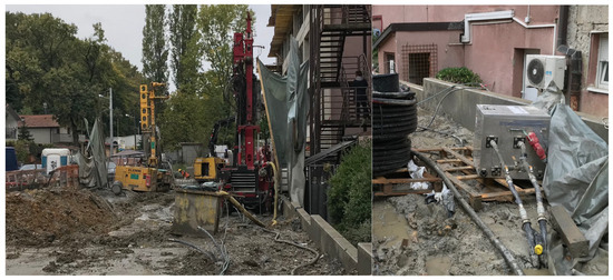
Figure 1.
Drilling operations at the construction site of the Institute for Medical Research and Occupational Health (IMI) and setup of TRT equipment at a test borehole of 120 m in depth.
The heating and cooling system was designed for GSHP (Figure 2) in combination with shallow geothermal energy extracted via BHEs. The heating system was designed to be comprised out of a 380 kW GSHP unit. The BHE field consists of 53 boreholes, with the depth of each BHE of 120 m and total pipe length of 6360 m. The BHE field is hydraulically separated into two separate fields—field A and field B. Northern field A is laid out in the form of a grid of 6 × 4 + 2, with a total of 26 boreholes, while the eastern field B is in the form of a grid of 13 × 2 + 1, with a total of 27 boreholes (Figure 3). The drilling diameter was 152 mm with the distance between each BHE 7 m. Closed single U-loop pipes (1U), with outer diameters of 45 mm (DN45) and wall thicknesses of 4.0 mm (SDR11), made of wear-resistant polyethylene material, were installed in the boreholes as a geothermal heat exchanger. When the exchanger was lowered into the borehole, the pipes were filled with water to maintain the hydrostatic counter-pressure in relation to the external pressure acting on the pipe. The selected tubes are grooved on the inner wall (the so-called Turbulator effect) to achieve a higher state of heat energy transfer from the fluid to the ground through the earlier formation of turbulent flow. When lowering the BHE pipe, dedicated centralizers were installed in the borehole, with two pipe holders, to maintain the distance between the supply and return pipes and to prevent pipe entanglement and torsional forces.
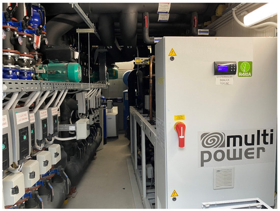
Figure 2.
Engineering room with geothermal heat pump operating in heating and cooling.
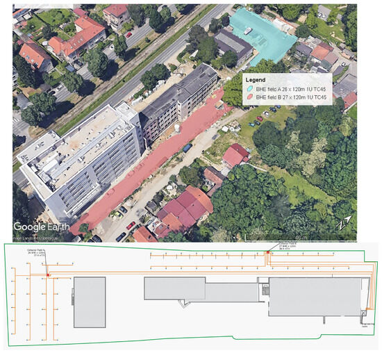
Figure 3.
Aerial view of the institute building and location of shallow geothermal field A and B [33] and layout of the BHE field A and B.
After installing the exchanger, each borehole was filled from top to bottom with a mixture of bentonite, cement, and water (60% bentonite clay and 40% cement). Special attention was paid to the possibility of loss of the mixture during cementation into possible fractures in the rock. Each well has a unit flow of 0.4 l/s (1.44 m3/r), which means that the total flow of the well field is 76.32 m3/h. Field A has 13 groups at the departure/return point, consisting of pipes of type PE100 DN40 SDR11 for connecting hydraulic groups of collector pipes from wells (collector pipes), while field B consists of 14 groups.
2.3. Geological and Thermogeological Settings of the Case Study
When developing shallow geothermal projects and assessing the thermogeological parameters of the rock, it is necessary to know the geological structure of the wider location. These data are important not only for the qualitative simulation of the thermal yields of a BHE but also for determining the drilling depth and the method of drilling and sealing the well during the completion phase. This is especially important when there is a presence of unconsolidated fine sand layers, which are a major cause of the borehole channel collapsing and drastically slowing down the BHE installation procedure. Therefore, it is necessary to know the hydrogeological aspects of the location, especially the presence of layers saturated with water with good hydraulic permeability. When modelling the BHE, the groundwater flow through the porous medium has a significant influence on the heat transfer between the BHE and the rock, as well as the thermal conductivity coefficient. The total heat transfer is then the sum of conduction, i.e., the conduction of heat through the rock matrix, and convection, which has a positive effect on the uniformity of the BHE temperature during two characteristic cycles of the heat pump. The geological structure of the wider Zagreb area is shown in Figure 4. The map [34,35] shows that in the area of Medvednica (IMI site location) and Samoborska gora, there are deposits on the surface with a wide chronostratigraphic range from the Paleozoic to the Quaternary. The Pliocene–Quaternary and Quaternary deposits are found on the surface of part of the Sava Valley (Zagreb and Samobor aquifers in the Sava river basin). Under them, deposits were drilled that partially correspond to those found in the area of Medvednica and Samoborska gora. Paleozoic and Mesozoic deposits were drilled in only a few boreholes, so they are described mainly on the basis of research at Medvednica, while Tertiary and Quaternary ones are described exclusively on the basis of analyses of drilled deposits in the research area of the Sava River valley. Pliocene and Quaternary deposits are made of diverse sediments. In the lower, Pliocene part, slightly sandy, calcareous clays with interlayers of coal, sand, and marl predominate, and in the upper Quaternary part, pebbles interlayered with sand and clay predominate. The location of the IMI facility is outside the area of alluvial deposits of the Zagreb aquifer, and it is located in the area of Pliocene deposits; Pl,Q—Pliopleistocene (gravel, sand, clay); Pl12—upper Pontian (sands, sandy and clayey marls); Pl11—lower Pontian—(marls, marly clays, sandstones and conglomerates) (Figure 4 left). Therefore, there are no layers saturated with water of good hydraulic conductivity at the considered location, and thus the entire heat transfer in the considered field would take place exclusively by conduction. A series of thermal response tests (TRT) were performed at the location to determine ground thermal conductivity (Figure 1 right).
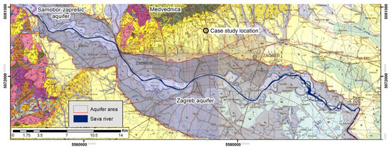
Figure 4.
The wider Zagreb area geological map [34,35]. Legend for geology map [34,35]: a—aluvium: gravels, sands and clays; a1—the lowest terrace: gravels, sands and clays to a lesser extent; a2—middle terrace: gravels and sands; pr—proluvium: gravels, sands and clays; l—clayey silt; lb—marshy loes: silty clays; Pl,Q—gravels, sands and clays; Pl11—marls, marly clays, sands to a lesser extent, sandstones, gravels and conglomerates (lower Pontian); Pl12—upper Pontian (sands, sandy and clayey marls); 2M31,2—lime marls, sands to a lesser extent, sandstones, gravels and conglomerates (upper Pannonian).
2.4. Simulation Scenarios for the BTES Field
The case study system currently operates with a BHE field consisting of 53 BHEs, each with 120 m depth. The system is used both for heating and cooling coupled with a 380 kW ground source heat pump. This setting is the base scenario V0, where the ground regenerates during summer since there the system operates also during the summer period and provides cooling to the building.
To assess the possibilities to store more thermal energy and assess effectiveness of additional storage to the operation of the entire system throughout the years, simulations were carried out based on assumption on using solar collectors as the source for the additional thermal energy. In the first variant, V1, the installation of solar panels and their use is assumed to add to the existing heat rejection from the GSHP during cooling cycle to the entire BHE field equally, and temperature response has been observed over assumed 20 years of operation.
The second variant, V2, presumes also 20 years of system operation for the simulation; however, in this case, the BHE field is divided in two. In field A, the energy from the cooling process is stored during summer, while field B stores energy from the solar panels. Since fields in this case would be hydraulically separated, each field would supply the building with half of the amount of energy for heating.
3. Results and Discussion
3.1. Thermal Response Test Results
The apparatus used for measuring was Precision Geothermal—model GeoCube500 (Precision Geothermal Inc., Maple Plain, MN, USA), with maximum power of 9.0 kW (3 × 2.5 kW + 1 × 1.5 kW) at a 240 V voltage. Data recording was performed with the Hobo U30 Series Data Logger (Onset Computer Corporation, Bourne, MA, USA), HOBOware Pro Software 2.4.0., at intervals of 5 min. For this project, the TRT was conducted over 144 h using a specialized Thermal Response Test with multiple heat steps—a novel method detailed in prior research [25,26,27] on four different BHE across the field. In this approach, each heat step continues until the temperature nearly stabilizes, achieving a steady-state condition. After stabilization, the heat load is adjusted, and the process is repeated with lower load, ensuring the maximum heat load is at least 1.5 times higher than the minimum. In low-conductivity ground, reaching steady-state conditions for high heat loads often requires significant time; hence, the semi-steady-state point is frequently used as an approximation. To reduce test duration, a reversible step-test sequence, decreasing from the highest to lowest heat load, is recommended. This method accurately determines the ground heat exchanger’s yield (W/m) for given inlet and outlet temperatures (EST—entering source temperature, LST—leaving source temperature, respectively). Applying step tests helps analyze borehole fluid behavior under prolonged peak loads, critical for understanding minimum borehole temperatures without excessive subcooling over time. The complete TRT procedure and temperature evolution during heat steps are depicted in Figure 5 for each of the four analyzed BHE.
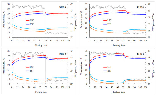
Figure 5.
Borehole inlet and outlet temperature evolution during the step TR test on the BHE-1,2,3,4.
It can be seen that the temperature evolution during the TR test for the same heat loads and time somewhat differed for each BHE. This is explained by the variation of the lithology up to depths of 120 m, as well as hydrogeological aspects of convection share in total heat transfer between borehole and ground in some thin sandy layers that were drilled. Also, different thermogeological properties of clay water saturation could play a major role in different thermal diffusivity properties for certain layers at different research areas. But the most influential parameter is the skin value for a certain borehole. Since there were different drilling companies involved in the work-out of the project, quality of borehole completion, which includes achieved geometry of pipes and grouting expertise, is considered a major factor that is responsible for different temperatures during the TR test for the same heating load. This is exactly the reason why in bigger geothermal fields, there is a necessity to test multiple BHE on a different part of the grid area. To calculate the rock’s mean thermal conductivity coefficient, the average circulating fluid temperature from the first heat step was plotted against the natural logarithm of time (ln(t)), as shown in Figure 6. After activating the heater, borehole exchanger temperatures rose as a function of the rock’s thermal conductivity. This analysis focused on the period after 24 h, allowing heat transfer stabilization and accounting for well and near-well thermal resistances. The selected interval (24–72 h) reflects an average thermal power of 5.41–5.46 kW across all four BHE.
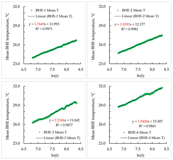
Figure 6.
Linearity of the average borehole temperature versus logarithm of time for BHE-1,2,3,4 and duration of the test between 24 and 72 h to determine the thermal conductivity coefficient.
The interpolated trendline slope from Figure 6 was different for each borehole. Using a 120 m well depth and an average heater power of 5.4 kW, the effective thermal conductivity coefficient for the marly-clay environment at the site was calculated using Eklof and Gehlin’s equation [23]. The obtained values were 2.07 W/m K (BHE-1); 1.96 W/m K (BHE-2); 1.59 W/m K (BHE-3); and 1.84 W/m K (BHE-4). If an average value is considered, it corresponds to 1.86 W/m K for entire research area.
With the calculated thermal conductivity and borehole geometry (length and diameter), thermal resistance was determined at 5 min intervals. This parameter includes thermal resistance from fluid to pipe (convection), through the pipe wall (conduction), and from the pipe wall to the surrounding grout and rock (conduction). Using equations (3–5), thermal resistance was calculated: 0.056 m K/W for BHE-1; 0.056 m K/W for BHE-1; 0.072 m K/W for BHE-2; 0.079 m K/W for BHE-3; and 0.1592 m K/W for BHE-4 (Figure 7). It is obvious that BHE-4 had a poor completion quality since above expected resistance was determined. The cause of this poor thermal resistance value was a combination of geometry of upward and downward pipe spacing in borehole and probably remaining air bubbles in the grout after cementation.
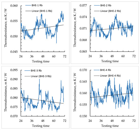
Figure 7.
Borehole thermal resistance trend during the TR test with a 5 min time step for BHE-1,2,3,4.
The IGSHPA guidelines recommend a minimum of 48 h for reliable TRT data. Figure 8 illustrates thermal conductivity variations over time, showing that results were stabilizing and became more representative after this time. Conducting tests shorter than this period increased uncertainty, and therefore this analysis showed that providing the TR test of 72 hr in length for the first period provides more than efficient data regarding thermal properties of the ground.
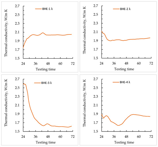
Figure 8.
Obtained trend of ground thermal conductivity during the TR test duration time for BHE-1,2,3,4.
In order to ascertain the maximum extraction and rejection heat rates achievable by a BHE as a function of a fixed EST, it was essential to establish the steady-state temperature for each test condition as an individual data point. As illustrated in Figure 9, it became feasible to create a diagram that depicted the extraction and rejection yield (W/m) as a function of the desired outlet temperature (EST). For the initial heating cycle condition, the temperature recorded after 72 h of the TR test was selected as the first stabilization point, even though actual steady-state heat transfer had not been completely established (a small margin of error is acceptable, as BHEs often do not operate at maximum load for extended durations). The second stabilization point corresponded to the temperature achieved at the conclusion of the second period. If a minimum permissible temperature of 0°C (according to EN14511) was established for the outlet of the exchanger during prolonged operation, accompanied by a constant heat load, a method for determining the heat exchanger yield rate, illustrated in Figure 9, was used. Each borehole was separately shown in first four upper figures in Figure 9, with its own temperature stabilization data and trendline that dictated fluid temperature (EST) due to a certain heat load applied to the heat exchanger. The bottom figure in Figure 9 shows all stabilization of the temperature for BHE-1,2,3,4, so that the mean extraction and rejection rates that could be applied to the entire geothermal field in the analysis and simulation of heat exchange for multi-decade operation are shown.
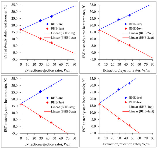
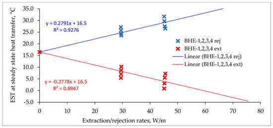
Figure 9.
Obtained borehole heat exchangers extraction and rejection heat loads under a steady-state heat transfer condition for each of the BHE-1,2,3,4 (upper four figures) and averaged heat loads for cumulative boreholes translated to the entire geothermal field (lowest picture).
Using the equation derived graphically for steady-state heat transfer of all BHE (y = −0.2778x + 16.5), the estimated steady-state extraction rate of the heat exchanger was calculated to be 59.4 W/m for an EST = 0 °C as tolerated minimum, translating to an averaged 7.13 kW for 120 m deep borehole heat exchangers in this case study.
One of the most important parameters in determining the yield of borehole heat exchangers is the thermal conductivity of the soil and rocks. In addition to the geological structure, the increase in thermal conductivity is influenced by the age of the rocks; the increase in depth and density; and the decrease in porosity, i.e., the volume fraction of the fluid in the pores, which is less thermally conductive than the rock matrix itself. In addition to thermal conductivity and the geothermal gradient, undisturbed soil temperature is an important element when evaluating shallow geothermal resources. Undisturbed soil temperature is defined as soil temperature at a depth where there is no influence of climate change and solar radiation. The initial temperature along the axis of the borehole can be determined during the performance of the TR test, which is an important parameter when sizing the geoexchange system or modeling its length. For the IMI location, the specified value was 16.5 °C. This analysis shows how important it is to have reliable data when performing sizing of the geothermal field and determining number of boreholes for every project.
3.2. Assessment of the Application of the Borehole Thermal Energy Storage Coupled with Solar Collectors
In order to evaluate the possibility of applying the BTES system to such a commercial building, it is necessary to consider certain settings. BTES principle is usually discussed when there is a necessity to recuperate the geothermal field after subcooling of the ground during the heating cycle in the winter (mostly with solar panels), or to reject excess heat to the ground from a local industry or energy utility company during summer and have a benefit of efficient system in the winter. Considering a BHE field in a climate setting where there is a need for cooling, it is assumed that during the cooling period, the thermal energy from the heat pump compressor and from the building’s space is stored in the ground. Then, any application of additional storage of thermal energy in the ground will impair the thermodynamic degree of utilization during cooling period, resulting from the increase in the temperature of the wellbore fluid.
Logically, the question arises as to whether BTES systems can even be applied in such climate areas where there is a need for significant cooling, in addition to dominant heating, given that the benefit obtained from the higher temperature of the well during the winter and the more favorable degree of utilization of the heat pump will certainly be impaired during summer in the cooling process.
The predicted energy needs of the building are necessary for modelling the required length of borehole heat exchanger for the system to work efficiently for a longer period of time. The design solution of the BHE system is dimensioned precisely for the specified energy required for heating and cooling of the building, ensuring the efficient operation of the system for 30 years. As this case analysis deals with the possibility of using the BTES system on the site by storing solar energy in the ground, there was an intention that the Institute for Medical Research and Occupational Health may decide to install thermal solar collectors in order to improve the efficiency of the geothermal system and maximize solar irradiance during the summer. Considering that the institute building is the tallest building in the area, and there is a hill opposite the building, and for this reason the Sun sets much earlier, 10% of the solar irradiance on the thermal solar collectors of a 30° slope surface, oriented south, was subtracted from the meteorological data. It should also be taken into account that the general efficiency of solar collectors is not 100% but an average of 80%, depending on the manufacturer.
Considering that in an environment such as in Zagreb (continental climate) there is a need for cooling in the summer, thermal energy taken from the heat pump compressor and thermal energy from the space is stored in the ground, any application of additional storage of thermal energy in the ground will impair the thermodynamic degree of utilization during cooling, due to the increase in the temperature of the BHE fluid. The calculations for this case study were made in three variants in the GHX Tool Box software 1.0to determine the potential of using the existing BHE field as a BTES system. For each variant, the cost of electricity to drive the heat pumps was calculated to compare different scenarios and savings when BTES is implemented on basis of sole operating costs.
As discussed previously, three variants were considered: The initial Variant 0 that only uses heating and cooling from geothermal field without applying BTES. Next, Variant 1 involves solar panels on the roof of the building and rejection of this heat to the borehole field during the entire year where the cooling process of the heat pump and solar BTES work in the same circulating system through boreholes. Variant 2 involves separation for the geothermal field during summer time into two separate hydraulic parts. One part of the borehole field is used to store solar heat through BTES, and the other part is solely used for cooling the building via heat pumps. During winter, both parts function separately as well, as each part of the field is supplying a different heat pump.
The heat flow in the ground is induced once the thermal imbalance in the ground occurs due to BHE operation. Once heat extraction begins due to temperature change, heat flow is induced from the surrounding rock, trying to achieve thermal equilibrium. From the simulation results shown in the following subchapters, it can be seen that the temperature drop or rise was in the function of logarithm of time, resulting in a decrease in temperature change over time. This means that over time, the heat flow tends to achieve a state of equilibrium or steady-state heat flow, meaning that the temperature change is most visible during first 20 years of BHE operation, after which time the change becomes less visible. Disregarding the limitations of the equipment and presuming no change in heating or cooling loads, after 20 years of operation, the outlet temperature would be close to stabilization, with smaller temperature changes than in the first years of operation. Therefore, the simulation was performed for 20 years for all variants, which is an also a typical period when designing real systems.
3.2.1. Variant BHE V0
In this variant, an initial heat transfer model of the geothermal system’s operation was made without using solar energy storage in the ground. This is the basic scenario on which the comparison is made with the possible variable scenarios of energy storage with the BTES system (Figure 10) to recuperate ground and elevate seasonal coefficient of performance (SCOP). Also, this is the design according to which the geothermal field was actually sized and installed. Annually, it is predicted that a system will consume 398.3 MWhth in the heating season and 159.6 MWhf in the cooling season. Peak loads are set at 371 kWth for heating and 266 kWf for cooling, which is actually delivered with a heat pump installed at the engineering room at the roof of a building. The system has currently been operating for almost two seasons, and the monitoring results are in line with predicted geothermal field temperature (entering source temperature—EST). This shows that sizing of the borehole heat exchanger field was a success since all heating and cooling needs are delivered 100% with shallow geothermal resources, with currently stated COP in heating above 4.5 and above 6.0 in cooling.
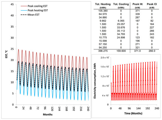
Figure 10.
Input power/energy parameters, results of BHE simulation, and heat pump electricity consumption in existing Variant V0 (both A26 + B27 fields) currently operating at the institute building.
3.2.2. Variant BTES V1
In this variant, a model with storage of heat to recuperate ground during the summer was discussed. The BTES system is discussed with the thermal energy obtained from the installed solar panels on the roof of the building (maximum considered area of 300 m2) and solar energy to be stored via the geothermal heat exchangers into the ground together with the cooling energy coming from the heat pump cooling process. The 300 m2 was obtained by analyzing several cases of increasing the solar collectors in the program from 50 m2 to 300 m2, where the final simulation was achieved when the temperatures at the exit from the BHE (entering source temperature—EST) during the peak summer days did not reach 45 °C, which is the thermodynamic limit of the operation of heat pumps in the cooling process. If additional solar surfaces were to be added, the operation of the cooling system would no longer be possible due to the too-high temperature of condensation in the heat pump (Figure 11). Initial energy from V0 stayed the same, but during summer, more heat was rejected into the ground. Therefore, peak load in cooling rose to 506 kWf, with 527 MWhf being rejected to the ground (cooling from heat pump and heat from solar panels). The heating cycle during winter stayed the same but operated at much greater efficiency, due to higher temperatures of the heat-saturated ground. Results of the simulation can be seen from Figure 11.
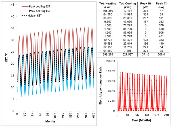
Figure 11.
Input power/energy parameters, results of BHE simulation, and heat pump electricity consumption in Variant V1 (both A26 + B27 fields operating as one uniform field).
3.2.3. Variant BTES V2
Unlike Variant 1, where BTES is performed alongside the cooling cycle of a heat pump on a homogenous geothermal field, this variant involves a different approach. A heat transfer model was set by dividing the geothermal field into the two separate fields: field A with 27 boreholes and field B with 26 boreholes. This was modelled in order to separate the BHE field that would only perform the cooling process of the heat pump during the summer (A26 field) and half of the heating loads of the building, while the other part of the field (B27) would store solar energy from panels into the ground during summer and cover the other half of heating loads from the building. It was assumed that there was no fluid mixing during the year, and that each field separately supplied its own compressor circuits inside the heat pump. In the field A26, the entire energy from the cooling process was stored during summer, namely, 159.6 MWhf, and half of the energy for heating of the building (199.1 MWhth) was produced during winter (Figure 12). In the field B27, half of the heating energy of 199.1 MWhth was also produced, and solar energy from panels was stored in the ground throughout the year, considering that field B27 did not participate in the cooling process of the facility (Figure 13). It is seen from Figure 13 that the EST would rise over time, which would lead to a decrease in efficiency during the cooling period. This means that the SCOP would also decrease over time, with only half of the field heated with solar collectors and the other half regenerated from cooling operations from the building.
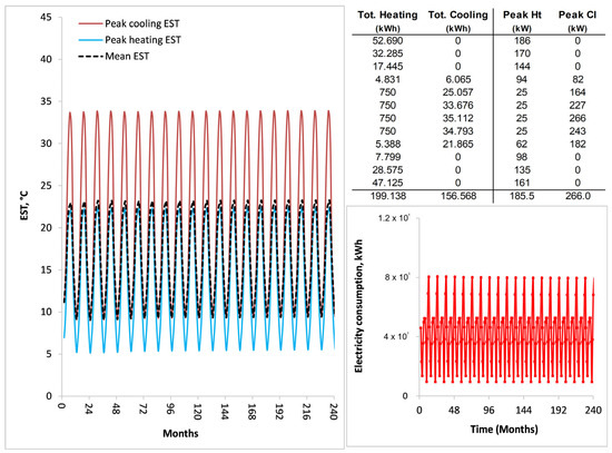
Figure 12.
Input power/energy parameters, results of BHE simulation, and heat pump electricity consumption in Variant V2 (field A26 operating with 1/2 of heating loads and full cooling loads of the building).
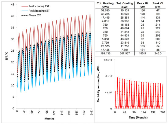
Figure 13.
Input power/energy parameters, results of BHE simulation, and heat pump electricity consumption in Variant V2 BTES (field A27 operating with 1/2 of heating loads and solar heat storage from the panels).
3.2.4. GSHP Consumption
Table 1 shows the consumption of electricity needed to operate the GSHP for each of the variants. It can be seen that the classic geothermal system without BTES (Variant V0) had a consumed electricity over 20 years of 1603 MWhe. Variant 1 had a significant cut in consumed electricity over the 20 years by almost 600 MWhe, while Variant 2 with separated fields provided only a reduction of 200 MWhe for the same time span. There is a question of economic justification to invest in solar panels to achieve this difference in electricity consumption, since additional investment for solar panels is needed. This research is the starting point for feasibility studies and implementation decisions in climate areas where cooling needs could not be neglected, such as in continental Croatia.

Table 1.
Consumption of electricity by heat pumps in different variants of the BTES system and standard geothermal system with no storage of heat.
In order to estimate the exact savings on electricity needed to drive the compressors of the geothermal heat pump by using solar collectors in the BTES system for 20 years of a project lifetime to which systems are usually designed, the amount of energy used for operation was calculated for all variants. The GHX program has the option of such a calculation since it contains information on the coefficient of performance during heating and cooling months for classic heat pump operation. In this way, it is possible to easily calculate for each month how much electricity consumption would be, considering the current efficiency as a function of average monthly temperatures. If the BTES system is designed in such a way that the geothermal field is homogenous (Variant V1), i.e., that all BHEs participate in heat transfer throughout the year during the heating and cooling periods and simultaneously store solar energy, then it can be seen from the simulation that the positive effects during the winter season are very visible in higher temperatures on the heat pumps (and causing also higher efficiency), but all the benefit is lost during the cooling season when the highest storage of solar energy in the ground through BTES is also performed at the same time. Then, the efficiency of the system is no longer even close to the values offered by the classic geothermal concept. If the well field is divided (Variant V2), then part of the field is used for heating and cooling the facility, and the other part of the field is used for heating and storing solar thermal energy. Considering that the second part of the field (BTES) is not used for cooling, then all the benefit during the winter months is seen as an increase in the efficiency of the heat pumps.
4. Conclusions
This research investigated possibilities of regenerating the rock using a solar thermal energy source in a borehole heat exchanger field coupled with a ground source heat pump in the climate of northern Croatia. The area is characterized by a cold winter and warm to hot summers, resulting in both heating and cooling needs, differing from usual colder climates where shallow BTES systems with BHEs usually in the range of 30–100 m are known to operate. A case study was chosen where a field with 53 BHEs, each 120 m in depth, is operating and where extensive thermal response tests were conducted to determine thermogeological properties. The obtained results were then used to simulate temperature change in three variants for 20 years. The base variant showed temperature evolution in a case where regeneration of the rock temperature was carried out by storing heat from the heat pump compressor and thermal energy from the building and without regeneration of the source rock with thermal energy from solar panels. Also, two variants of implementing borehole thermal energy storage (BTES) were considered to regenerate rock thermal energy by installing solar panels. The first variant presumed the entire BHE field operates as a uniform field, storing thermal energy during the cooling period from both the solar panels and heat pump. Since the field is divided into two sections, each with its own hydraulic collector group, the second variant presumed that one field stores thermal energy only from solar panels and the other from a heat pump.
After performing simulations using the GHX program, it was evident that the use of solar energy regenerated the temperature of the fluid in the BHE field, as expected and according to the variants presented. The point of using the BTES system in combination with the use of shallow geothermal energy is the higher efficiency of heat pumps in winter, considering the stored thermal energy during summer. However, during the cooling season, the system was visibly less efficient compared to the classic use of shallow geothermal energy resources. This occurs because the temperature on the condenser is significantly higher during the summer months, so the geothermal heat pump no longer has an advantage over the classic air heat pump systems. Also, the solar panel surface was set at 300 m2 because the maximum temperatures in the BHE reached 40 °C (EST), which is considered the upper maximum for normal operation of the system. From the shown simulations, it can be seen that such systems could work better in climate areas where there is less need for cooling. However, it should also be taken into account that the solar insolation is lower the further north geographically the project is located. If there are mountainous areas, the problem arises in the daily available solar radiation, considering the mountainous landscape. The temperature should also not rise above 45 °C in the BHE due to the use of polyethylene pipes not resilient to higher temperatures.
The results of the simulations indicate that the simultaneous operation of the geothermal heating and cooling system alongside the BTES solar energy storage system is not technologically or economically feasible for the climate of northern Croatia. The primary reason for this is that any efficiency improvements gained from solar regeneration of the ground in the heating system during winter are negated during the cooling season due to the thermodynamic operation mode of heat pumps. Consequently, such storage systems are only justifiable in cooler regions and where there is excess thermal energy available for storage from industrial or energy systems. In order to confirm these findings, further research should focus on researching possibilities of implementing BTES systems and rock temperature regeneration in climates with both heating and cooling needs in high-temperature heat pump thermotechnical systems where higher temperatures during winter, such as in industry, are needed.
The BHE fields are generally designed based on the techno-economic criterion that the minimum temperature at the entrance to the heat pumps does not fall below 0 °C even after 30 years of operation. This temperature has practically been selected through a long series of years of operation of geothermal systems in the world and offers the optimal cost of drilling and the obtained efficiency on the heat pump. Therefore, BTES projects incorporated on a classic shallow geothermal project can elevate SCOP in a system to some extent, but in climates where cooling is not negligible, there is no economic justification of implementation, as seen from the economic comparison of the operating costs of the GSHP. Therefore, BTES systems coupled with solar collectors have more economic feasibility when employed in colder climates as a measure to recuperate ground energy during summer months.
Author Contributions
Conceptualization, T.K.; methodology, T.K.; software, T.K. and V.G.; validation, M.M.; formal analysis, T.K. and M.M.; investigation, V.G.; data curation, M.M.; writing—original draft preparation, T.K., M.M. and V.G.; writing—review and editing, T.K. and M.M. All authors have read and agreed to the published version of the manuscript.
Funding
This work was supported by the Croatian Science Foundation under the project number HRZZ-IP-2022-10-4206.
Institutional Review Board Statement
Not applicable.
Informed Consent Statement
Not applicable.
Data Availability Statement
The original contributions presented in this study are included in the article. Further inquiries can be directed to the corresponding author.
Conflicts of Interest
Veronika Galović was employed by Croatian Transmission System Operator (HOPS). The remaining authors declare that the research was conducted in the absence of any commercial or financial relationships that could be construed as a potential conflict of interest.
Nomenclature
| borehole heat exchanger diameter, (mm) | |
| Euler number (2.7183) | |
| exponential integral | |
| EST | entering source temperature (°C) |
| borehole depth (m) | |
| LST | leaving source temperature (°C) |
| heat power per meter of a borehole, (W/m) | |
| heat power, (W) | |
| radius, (m) | |
| borehole radius, (m) | |
| equivalent borehole thermal resistance, (m K/W) | |
| skin factor, - | |
| time, (s) | |
| temperature, (°C) | |
| initial borehole temperature, (°C) | |
| temperature in function of radius and time, (°C) | |
| Greek symbols | |
| thermal diffusivity, (m2/s) | |
| temperature drop/rise due to skin effect, (°C) | |
| Euler’s constant () | |
| thermal conductivity, (W/m K) | |
| slope of the line | |
| Abbreviations | |
| ATES | aquifer thermal energy storage |
| BTES | borehole thermal energy storage |
| BHE | borehole heat exchanger |
| CTES | cavern thermal energy storage |
| DHS | district heating system |
| GHSP | ground source heat pump |
| TRT | thermal response test |
| STES | seasonal thermal energy storage |
| UTES | underground thermal energy storage |
References
- Fleuchaus, P.; Godschalk, B.; Stober, I.; Blum, P. Worldwide application of aquifer thermal energy storage—A review. Renew. Sustain. Energy Rev. 2018, 94, 861–876. [Google Scholar] [CrossRef]
- Drijver, B.; van Aarssen, M.; Zwart, B.D. High-temperature aquifer thermal energy storage (HT-ATES): Sustainable and multi-usable. In Proceedings of the 12th International Conference on Energy Storage, Lleida, Spain, 16–18 May 2012. [Google Scholar]
- Penttinen, P.; Vimpari, J.; Junnila, S. Optimal seasonal heat storage in a district heating system with waste incineration. Energies 2021, 14, 3522. [Google Scholar] [CrossRef]
- Skarphagen, H.; Banks, D.; Frengstad, B.S.; Gether, H. Design considerations for borehole thermal energy storage (BTES): A review with emphasis on convective heat transfer. Geofluids 2019, 1, 4961781. [Google Scholar] [CrossRef]
- Sibbitt, B.; McClenahan, D.; Djebbar, R.; Thornton, J.; Wong, B.; Carriere, J.; Kokko, J. The performance of a high solar fraction seasonal storage district heating system—Five years of operation. Energy Procedia 2012, 30, 856–865. [Google Scholar] [CrossRef]
- Rad, F.M.; Fung, A.S. Solar community heating and cooling system with borehole thermal energy storage—Review of systems. Renew. Sustain. Energy Rev. 2016, 60, 1550–1561. [Google Scholar] [CrossRef]
- Tinti, F.; Tassinari, P.; Rapti, D.; Benni, S. Development of a pilot borehole storage system of solar thermal energy: Modeling, design, and installation. Sustainability 2023, 15, 7432. [Google Scholar] [CrossRef]
- Nilsson, E.; Rohdin, P. Performance evaluation of an industrial borehole thermal energy storage (BTES) project—Experiences from the first seven years of operation. Renew. Energy 2019, 143, 1022–1034. [Google Scholar] [CrossRef]
- Pilou, M.; Kosmadakis, G.; Meramveliotakis, G.; Krikas, A. Towards a 100% renewable energy share for heating and cooling in office buildings with solar and geothermal energy. Sol. Energy Adv. 2022, 2, 100020. [Google Scholar] [CrossRef]
- Saloux, E.; Candanedo, J.A. Sizing and control optimization of thermal energy storage in a solar district heating system. Energy Rep. 2021, 7, 389–400. [Google Scholar] [CrossRef]
- Catolico, N.; Ge, S.; McCartney, J.S. Numerical modeling of a soil-borehole thermal energy storage system. Vadose Zone J. 2016, 15, 1–17. [Google Scholar] [CrossRef]
- Gehlin, S. Thermal Response Test: Method Development and Evaluation. Ph.D. Thesis, Luleå University of Technology, Luleå, Sweden, 2002. [Google Scholar]
- Drake Landing Solar Community, Okotoks, Alberta. Available online: https://www.okotoks.ca/sites/default/files/2024-10/Drake%20Landing%20Solar%20Community%20Background.pdf (accessed on 24 January 2025).
- Andresen, H.T.; Li, Y. Modelling the heating of the Green Energy Lab in Shanghai by the geothermal heat pump combined with the solar thermal energy and ground energy storage. Energy Procedia 2015, 70, 155–162. [Google Scholar] [CrossRef][Green Version]
- Bauer, D.; Marx, R.; Nußbicker-Lux, J.; Ochs, F.; Heidemann, W.; Müller-Steinhagen, H. German central solar heating plants with seasonal heat storage. Sol. Energy 2010, 84, 612–623. [Google Scholar] [CrossRef]
- Malmberg, M. Transient Modeling of a High Temperature Borehole Thermal Energy Storage Coupled with a Combined Heat and Power Plant. Master’s Thesis, KTH Industrial Engineering and Management, Stockholm, Sweden, 2017. [Google Scholar]
- Aldubyan, M.; Chiasson, A. Thermal study of hybrid photovoltaic-thermal (PVT) solar collectors combined with borehole thermal energy storage systems. Energy Procedia 2017, 141, 102–108. [Google Scholar] [CrossRef]
- Lizana, J.; Ortiz, C.; Soltero, V.M.; Chacartegui, R. District heating systems based on low-carbon energy technologies in Mediterranean areas. Energy J. 2017, 120, 397–416. [Google Scholar] [CrossRef]
- Panno, D.; Buscemi, A.; Beccali, M.; Chiaruzzi, C.; Cipriani, G.; Ciulla, G.; Di Dio, V.; Brano, V.L.; Bonomolo, M. A solar assisted seasonal borehole thermal energy system for a non-residential building in the Mediterranean area. Sol. Energy 2019, 192, 120–132. [Google Scholar] [CrossRef]
- Renaldi, R.; Friedrich, D. Techno-economic analysis of a solar district heating system with seasonal thermal storage in the UK. Appl. Energy 2019, 236, 388–400. [Google Scholar] [CrossRef]
- Clauß, J.; Taveres-Cachat, E.; Alonso, M.J. Performance evaluation and control scenarios for targeted heat injection and extraction in an existing geothermal borehole field in Norway. Appl. Therm. Eng. 2024, 236, 121468. [Google Scholar] [CrossRef]
- Nimac, I.; Herceg-Bulić, I.; Žuvela-Aloise, M. The contribution of urbanisation and climate conditions to increased urban heat load in Zagreb (Croatia) since the 1960s. Urban Clim. 2022, 46, 101343. [Google Scholar] [CrossRef]
- Eklöf, C.; Gehlin, S. A Mobile Equipment for Thermal Response Test. Master’s Thesis, Luleå University of Technology, Luleå, Sweden, 1996. [Google Scholar]
- Kurevija, T.; Strpić, K.; Koščak-Kolin, S. Applying petroleum the pressure buildup well test procedure on thermal response test—A novel method for analyzing temperature recovery period. Energies 2018, 11, 366. [Google Scholar] [CrossRef]
- Kurevija, T.; Macenić, M.; Strpić, K. Steady-state heat rejection rates for a coaxial borehole heat exchanger during passive and active cooling determined with the novel step thermal response test method. Rud.-Geološko-Naft. Zb. 2018, 33, 61–71. [Google Scholar] [CrossRef]
- Kurevija, T.; Macenić, M.; Borović, S. Impact of grout thermal conductivity on the long-term efficiency of the ground-source heat pump system. Sustain. Cities Soc. 2017, 31, 1–11. [Google Scholar] [CrossRef]
- Kurevija, T.; Strpić, K. Hydraulic and thermogeological design differences between two-loop vertical and inclined coaxial borehole heat exchangers. Renew. Energy 2018, 117, 314–323. [Google Scholar] [CrossRef]
- Carslaw, H.S.; Jaeger, J.C. Conduction of Heat in Solids; Clarendon Press: Oxford, UK, 1959. [Google Scholar]
- Lee, J. Well Testing, 1st ed.; Society of Petroleum Engineers of AIME: New York, NY, USA, 1982. [Google Scholar]
- Ingersoll, L.R.; Zobel, O.J. An Introduction to the Mathematical Theory of Heat Conduction; Ginn and Company: Boston, MA, USA, 1913. [Google Scholar]
- Eskilson, P. Thermal Analysis of Heat Extraction Boreholes. Ph.D. Thesis, University of Lund, Lund, Sweden, 1987. [Google Scholar]
- Chiasson, A.D. Geothermal Heat Pump and Heat Engine Systems: Theory and Practice; John Wiley & Sons Ltd.: Hoboken, NJ, USA, 2016. [Google Scholar]
- Google Earth. Image Landsat/Copernicus. Image @ 2024 Maxar Technologies. Available online: https://earth.google.com/web/@45.83435097,15.97829955,164.46007188a,244.17035392d,35y,304.15882195h,46t,-0r/data=ChYqEAgBEgoyMDIyLTA1LTE1GABCAggBOgMKATBCAggASg0I____________ARAA (accessed on 19 August 2024).
- Šikić, K.; Basch, O.; Šimunić, A. Osnovna Geološka Karta SFRJ 1:100.000, List Zagreb L33–80; Institut za Geološka Istraživanja: Zagreb, Croatia; Savezni Geološki Institut: Belgrade, Serbia, 1978. [Google Scholar]
- Basch, O. Osnovna Geološka Karta SFRJ 1:100.000, List Ivanić-Grad L33–81; Geološki Zavod: Zagreb, Croatia; Savezni Geološki Institut: Belgrade, Serbia, 1983. [Google Scholar]
Disclaimer/Publisher’s Note: The statements, opinions and data contained in all publications are solely those of the individual author(s) and contributor(s) and not of MDPI and/or the editor(s). MDPI and/or the editor(s) disclaim responsibility for any injury to people or property resulting from any ideas, methods, instructions or products referred to in the content. |
© 2025 by the authors. Licensee MDPI, Basel, Switzerland. This article is an open access article distributed under the terms and conditions of the Creative Commons Attribution (CC BY) license (https://creativecommons.org/licenses/by/4.0/).