Article

A Deep Learning-Based Method for Inrush Current Identification in Modern Sustainable Power Systems

1
Guodian Nanjing Automation Co., Ltd., Nanjing 210031, China
2
Nanjing SAC Automation Co., Ltd., Nanjing 211153, China
3
School of Electrical Engineering, Southeast University, Nanjing 210018, China
4
School of Electrical Engineering, Xi’an Jiaotong University, Xi’an 710049, China
*
Authors to whom correspondence should be addressed.
Sustainability 2025, 17(23), 10502; https://doi.org/10.3390/su172310502
Submission received: 18 October 2025 / Revised: 21 November 2025 / Accepted: 22 November 2025 / Published: 24 November 2025

Abstract

During system faults, power electronic converters in modern sustainable power systems activate low-voltage ride-through (LVRT) control strategies, which introduce second harmonic current into the power system. For transformer protection, the conventional inrush current identification method based on second harmonic current fails to adapt to the high harmonic conditions of electronic power-based sources in renewable energy systems. This paper proposes an identification scheme based on a modified MobileNetV4 (MNv4) architecture and multi-source electrical quantities. The experimental dataset is constructed through PSCAD simulation and engineering field data. The input feature combination including three-phase voltage, current and differential current is designed, which solves the defects of single feature in traditional methods. Experiments show that the MNv4 model delivers competitive performance in terms of accuracy and recall, while featuring a small number of parameters that make it suitable for resource-constrained embedded deployment. This research provides theoretical support and data paradigm for the engineering application of artificial intelligence in the field of relay protection.

1. Introduction

Under China’s dual-carbon goals, the energy transition is advancing rapidly. The power grid now integrates a high penetration of renewable energy. Solar PV and wind power have demonstrated remarkable growth. By the end of 2024, China’s renewable capacity reached 1.89 billion kW, representing 56.4% of total installed power capacity. Wind and solar energy will form the backbone of China’s future zero-carbon power system. Transformers, as critical components in modern sustainable power systems, perform essential functions of voltage conversion and power transmission. Their reliable operation is fundamental to overall system security and stability. In scenarios such as no-load transformer energization, external fault clearance, or adjacent transformer no-load switching, the magnetizing branch experiences magnetic saturation due to reduced magnetic reluctance. This results in a surge of magnetizing current, with peak values reaching 6–8 times the transformer’s rated current [1]. Since the magnetizing current can cause differential current, it is necessary to quickly identify the magnetizing inrush current to prevent misoperation of protection [2,3,4].
Traditional magnetizing inrush current identification methods mainly include the second-harmonic principle, the interrupted-angle principle, and the waveform symmetry principle [5,6]. The second-harmonic principle is based on the fact that the magnetizing inrush current contains a large number of second-harmonic components, and this method is currently widely used. However, faults in modern sustainable power systems can cause voltage dips. The converters then activate low-voltage ride-through (LVRT) control strategies. This strategy introduces significant second-harmonic components. Consequently, the second-harmonic principle may misidentify faults. Such errors can cause differential protection failure during internal faults and maloperation during external faults.
The researchers have also developed magnetizing inrush identification techniques through algorithmic innovations, adaptive threshold methodologies, DC offset characteristics analysis, phase-angle differential criteria, and time-frequency domain decomposition. Recent research initiatives have adopted voltage-based approaches, leveraging the distinct terminal voltage characteristics during magnetizing inrush conditions versus fault scenarios to determine transformer operational states. Furthermore, integrated identification methodologies combining both voltage and current signatures [7] have been developed to enhance discrimination reliability. However, the performance of traditional identification methods is fundamentally constrained by their dependence on a single feature of either voltage or current. This inherent limitation compromises their generalizability across diverse and complex field conditions, often resulting in operational failures. With the progress of science and technology, new technologies such as wavelet transform [8] and neural networks have been widely used in the field of transformer protection.
With the rapid evolution of AI technologies (e.g., deep learning, reinforcement learning), transformer magnetizing inrush identification has progressed beyond conventional harmonic analysis to data-driven intelligent discrimination methods [9,10,11,12,13,14,15]. Artificial intelligence exhibits robust pattern recognition and big data processing capabilities, enabling autonomous feature extraction and characteristic pattern learning from massive substation datasets, which facilitates accurate classification of diverse fault conditions. For instance, Reference [1] developed a hybrid power transformer differential protection scheme integrating Lightweight Gated Recurrent Unit (LGRU) and Convolutional Neural Network (CNN) architectures. It combines the advantages of the two models, can effectively distinguish between transformer magnetizing inrush current and internal faults, and shows reliability and robustness under various conditions. Reference [2] introduced a Fast Gated Recurrent Neural Network (FGRNN) that addresses the challenges of noise sensitivity and transient feature extraction in transformer differential protection. By eliminating the GRU’s reset gate and employing a mutual information-based loss function, the model effectively discriminates between magnetizing inrush currents and internal faults. Reference [3] developed an LSTM-based identification model for magnetizing inrush currents, effectively preventing differential protection misoperation during transformer no-load switching. The LSTM network effectively models transformer current signals, capturing their temporal dependencies and adapting to dynamic variations. However, recurrent neural networks are primarily designed for sequence prediction tasks and are less commonly applied to classification problems. The main reasons are threefold: First, RNNs inherently assume sequential dependencies in input data, an inductive bias that makes them suboptimal for magnetizing inrush current identification tasks. Second, RNNs suffer from gradient vanishing and explosion problems during long-sequence training. Additionally, they face challenges in parallel training and require high computational costs.
CNNs extract local features through convolutional kernel operations and have demonstrated remarkable success in domains such as image recognition and speech processing [12]. In transformer magnetizing inrush current identification, CNNs can directly process current waveform signals and automatically extract features in an end-to-end manner, enabling accurate classification of fault conditions. Reference [5] proposed a transformer differential protection scheme based on an Accelerated Convolutional Neural Network (A-CNN). By incorporating vector compression technology and other CNN enhancements, this approach addresses the limitations of conventional methods, including their heavy computational burden and reliance on preset thresholds, thereby significantly improving both the reliability and operating speed of the protection. Reference [6] proposed a transformer protection scheme based on a Discriminative Feature-Focused Convolutional Neural Network (DFF-CNN). By designing a three-module network architecture comprising a feature encoder and dual classifiers, this approach effectively addresses three key limitations of conventional magnetizing inrush current identification methods: threshold dependency, single-feature reliance, and poor generalization capability. Reference [7] developed a transformer fault diagnosis model combining Discrete Wavelet Transform (DWT) with a 1D CNN-LSTM network. This hybrid approach addresses two critical challenges in transformer differential protection: (1) inaccurate inrush current identification and (2) prolonged execution time. The solution employs DWT for differential current feature extraction and utilizes the 1D CNN-LSTM architecture for accurate classification. While AI-based techniques address the shortcomings of conventional methods that use a single feature, they face two major challenges: firstly, their performance remains unstable due to the dependence on a single analog input; secondly, the substantial computational burden of these models makes them difficult to deploy in embedded protection systems.
This paper conducts a comprehensive analysis of magnetizing inrush current generation mechanisms and their adverse effects on transformer protection. We propose a novel identification framework integrating modified MNv4 architecture with multi-source electrical quantity fusion. The study establishes a dataset (thousands of samples) combining PSCAD simulations with field measurements from a power system and designs a multidimensional input feature matrix incorporating three-phase voltage, current, and differential current characteristics.
Based on the waveform distortion rate principle, conventional methods such as the interrupted angle and waveform symmetry techniques identify inrush currents by detecting characteristics of waveform distortion. Similarly, harmonic content identification methods based on the harmonic frequency principle discriminate inrush currents by analyzing their frequency features. However, both individual and fused criteria of these methods inevitably suffer from the limitation of relying solely on current characteristics. In cases where transformer core saturation is mild or sympathetic inrush occurs, the waveform distortion rate and harmonic content may both be relatively low, leading to failure of these conventional methods. In contrast, the scheme proposed in this paper not only incorporates multi-dimensional electrical quantities, including three-phase voltages, three-phase currents, and differential currents, but also leverages deep learning techniques to exploit both waveform characteristics and the temporal correlation of voltage and current variations.
The proposed scheme effectively overcomes the limitations of traditional identification methods that rely solely on current features, thereby addressing their lack of generalizability. Simultaneously, it resolves critical issues prevalent in existing AI-based solutions, including unstable identification accuracy caused by univariate input, high computational complexity, and practical deployment challenges in embedded devices. The research establishes both theoretical foundations and practical data standards for implementing AI-driven solutions in relay protection.

2. Classification and Generation Mechanisms of Magnetizing Inrush Current

2.1. Classification of Magnetizing Inrush Current

Transformer magnetizing inrush current can be classified into two types based on generation conditions: The first type is load recovery inrush current, which occurs when a transformer is re-energized under load conditions. The second type includes no-load switching inrush current (affecting the transformer itself) and sympathetic inrush current (affecting parallel/series transformers) during no-load [16]. Both inrush phenomena significantly influence transformer dynamics and grid stability, particularly in protection system reliability and equipment mechanical stress.
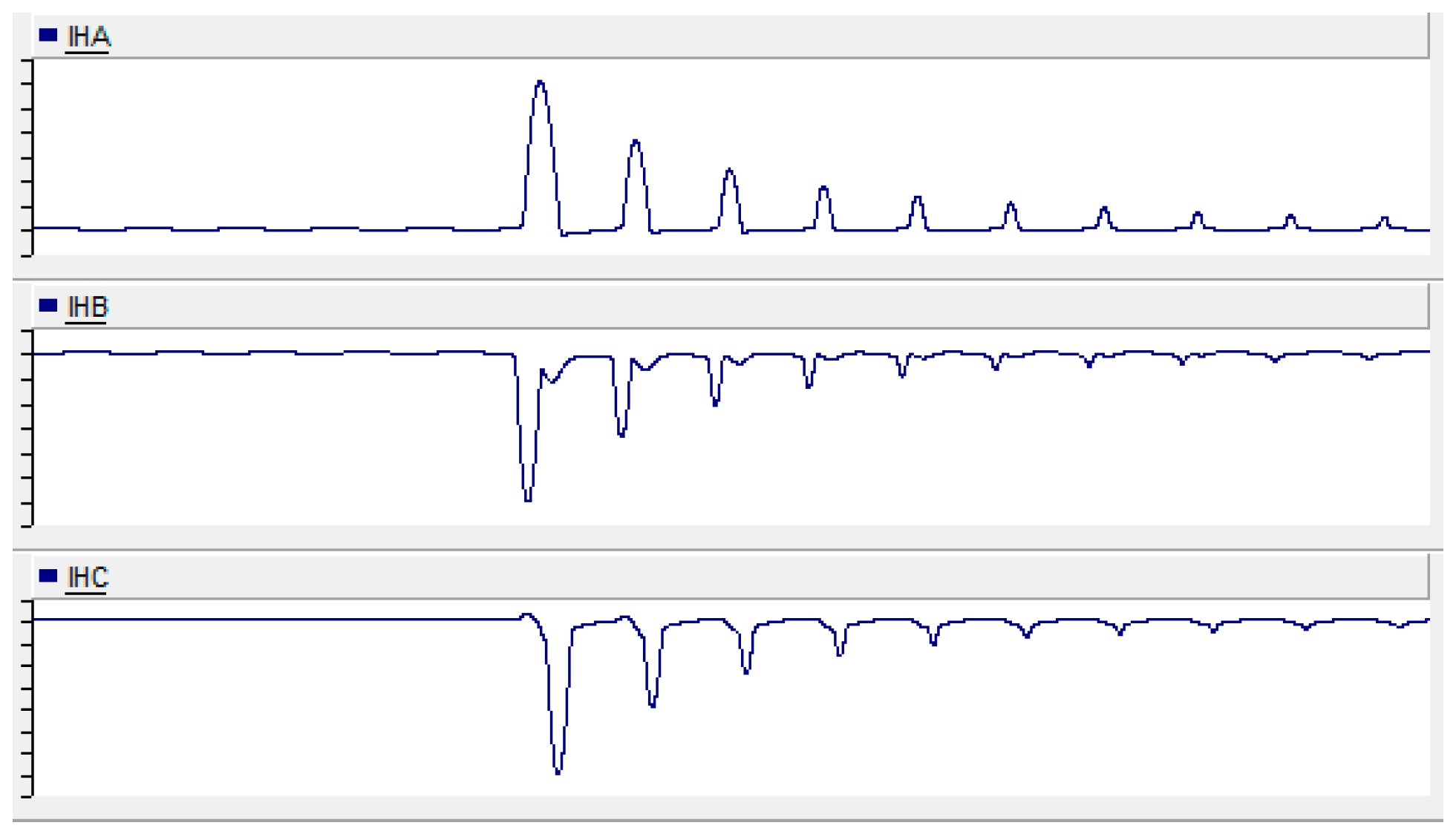
Recovery magnetizing inrush current refers to the transient current generated during transformer re-energization following fault clearance, resulting from the interaction between the residual magnetic flux in the core and the instantaneous power system voltage. This phenomenon typically occurs upon transformer closing or fault recovery and persists for several cycles until seconds before decaying [17]. The current waveform is illustrated in Figure 1.
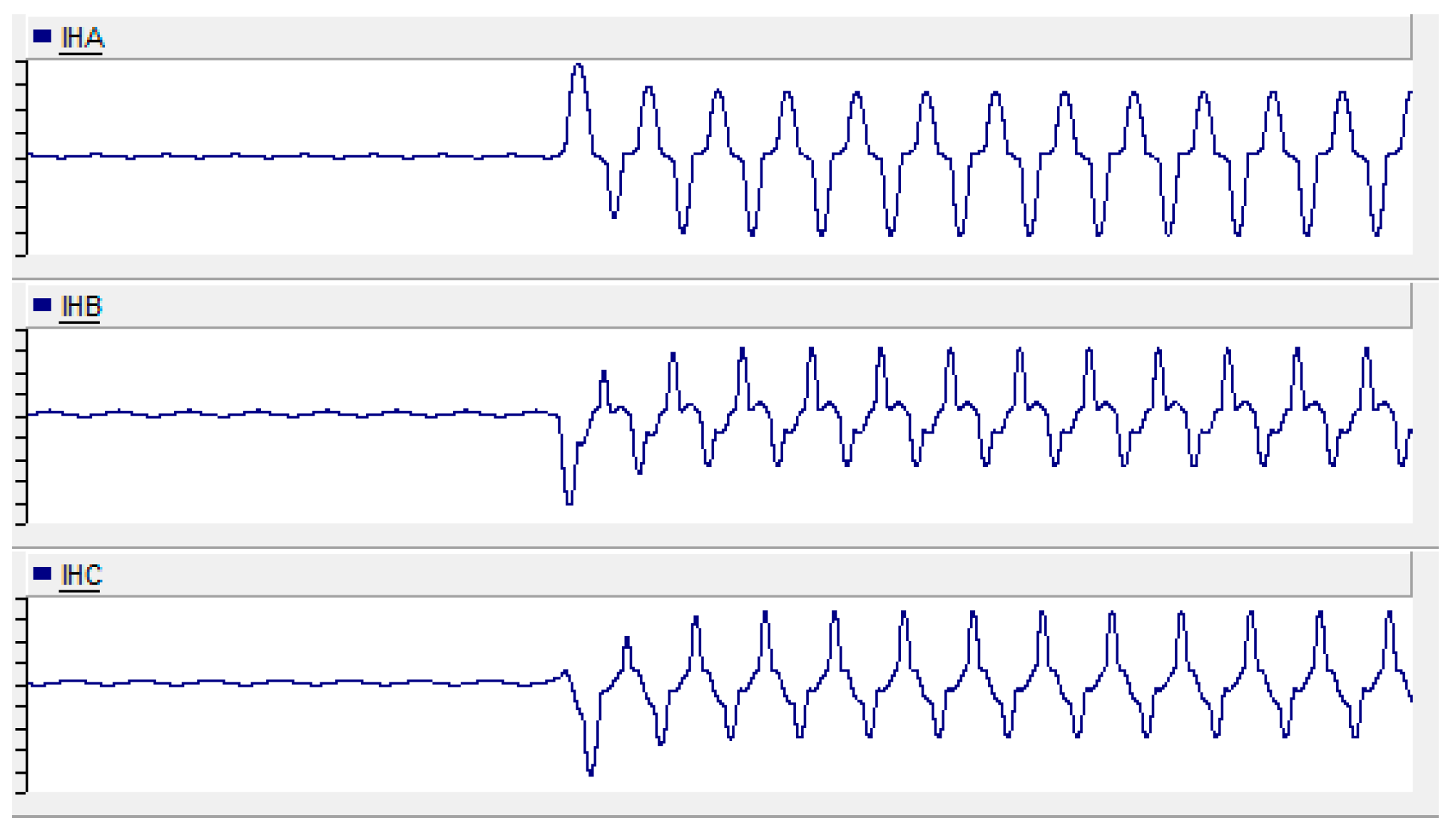
No-load closing magnetizing inrush current refers to the transient current phenomenon occurring during transformer energization under no-load conditions, resulting from the core flux dynamics. When energized, the sudden application of supply voltage induces a non-periodic flux component due to the core’s inherent flux continuity. This DC flux component superimposes with the steady-state AC flux, driving the core into saturation and generating an inrush current that can reach 6–10 times the rated current. The current waveform is illustrated in Figure 2.
Resonant inrush current occurs when an energized transformer generates additional inrush current. This happens during no-load energization of parallel or series-connected transformers in the same power system. The induced current appears after a delay, shows polarity reversal, rises to peak value, then decays gradually [18]. The current waveform is illustrated in Figure 3.

2.2. Generation Mechanisms of Magnetizing Inrush Current

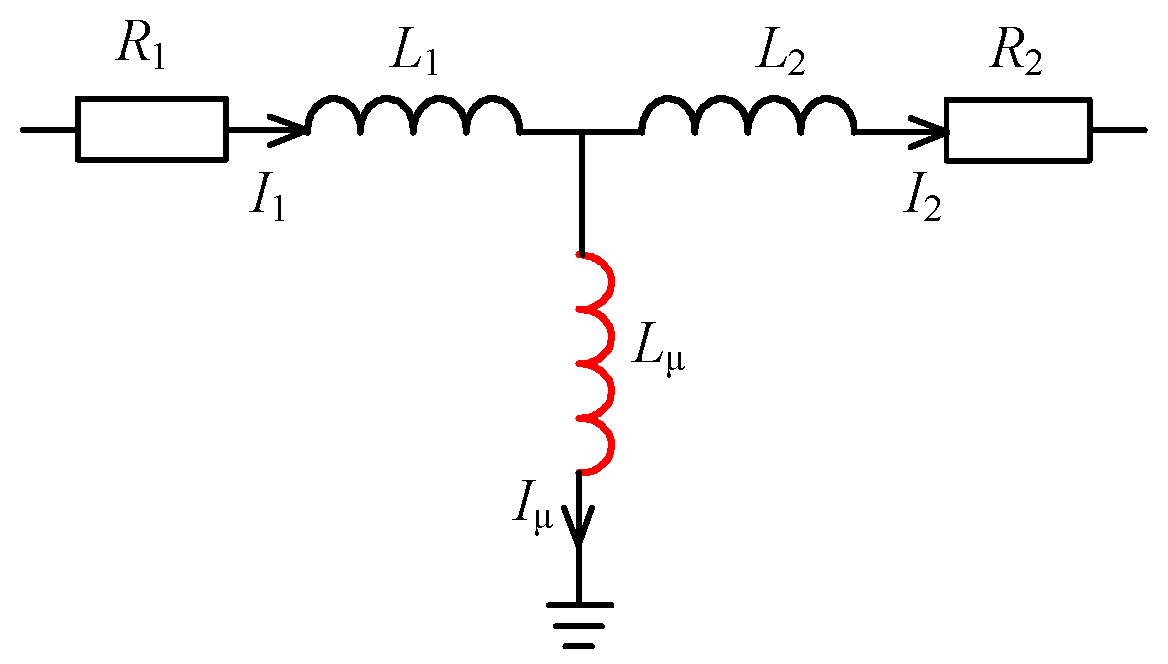
The magnetizing inrush current fundamentally originates from core saturation caused by the transformer’s ferromagnetic characteristics [19]. To demonstrate this phenomenon, consider a single-phase transformer case study. Figure 4 presents the equivalent circuit of such a transformer under no-load switching conditions. R 1 represents the equivalent resistance on the closing side, L 1 denotes the equivalent leakage inductance on the closing side, L μ stands for the equivalent magnetizing inductance, and R 2 corresponds to the equivalent resistance on the no-load side.
The primary-side voltage of the transformer is
u 1 = U m sin ( ω t + α )
The core magnetic flux and applied voltage relationship during no-load energization satisfies
N 1 d d t + i μ R 1 = U m sin ( ω t + α )
The core magnetic flux during no-load energization can be expressed as
ϕ = ϕ m cos ω t + α + ϕ m cos α + ϕ r exp ( R 1 L 1 t )
In the formula, φ m = U m / ω is the amplitude of the magnetic flux corresponding to the voltage. ϕ m cos ( ω t + α ) denotes the steady-state magnetic flux component, ϕ m cos α + ϕ r denotes the transient magnetic flux component, and ϕ r indicates the residual magnetism present in the transformer core prior to energization. The magnitude and polarity are intrinsically determined by the instantaneous core magnetic flux condition at the switching instant.
The magnetic flux during no-load switching of a transformer depends on the switching angle. When switching at the voltage zero-crossing point, the flux reaches its maximum value one quarter cycle after switching. Its maximum value is φ max 2 φ m + φ r and the maximum flux significantly exceeds the saturation flux, causing severe transformer saturation.
Under normal operating conditions, a power transformer typically experiences voltage fluctuations within ±10% of its rated value. Consequently, the resulting magnetic flux density remains below the saturation threshold, ensuring the core operates within its linear magnetization region. During the no-load energization transient of power transformers, the superposition of transient magnetic flux components may drive the total core flux density beyond the saturation limit, thereby inducing magnetic saturation in the transformer core [20]. Under the condition where both the residual flux density and transient flux component exhibit positive polarity, the resultant peak flux density attains its maximum magnitude after a half-cycle of the power frequency. Particularly when energization occurs at the voltage zero-crossing instant, the cumulative flux density may significantly exceed the core’s saturation threshold, thereby inducing severe magnetic saturation in the transformer core.
The excitation current can be expressed as
I = φ / L μ
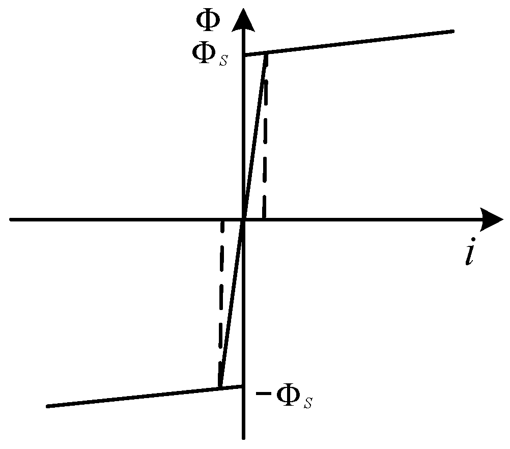
The excitation inductance varies dynamically with transformer core saturation, being large under unsaturated conditions and decreasing sharply during saturation. Thus, the core excitation characteristic can be approximated by a two-segment linear curve, as shown in Figure 5. Consequently, the current waveform no longer follows a linear relationship with the flux waveform, as illustrated in Figure 6.
As shown in Figure 6, when the flux exceeds the transformer saturation flux, the current surges and waveform distortion occurs, accompanied by significant harmonic content.

2.3. Harmonic Characteristics of Transformer Magnetizing Inrush Current

Differential protection is the primary protection for transformers, with its basic principle illustrated in Figure 7. Under normal operation, I 1 = I 2 and I μ = 0 . So the differential current I d = I 1 + I 2 = 0 . During transformer faults, I 1 I 2 and I d = I 1 + I 2 0 . However, under non-fault conditions with core saturation, I μ 0 , leading to I 1 I 2 , I d = I 1 + I 2 0 , which may cause differential protection misoperation. To prevent this, core saturation must be identified. In practice, this is achieved by detecting the second harmonic content in the current. When the ratio of the second harmonic current to the fundamental current exceeds 15%, the transformer core is deemed saturated, and the differential protection is blocked to avoid misoperation.
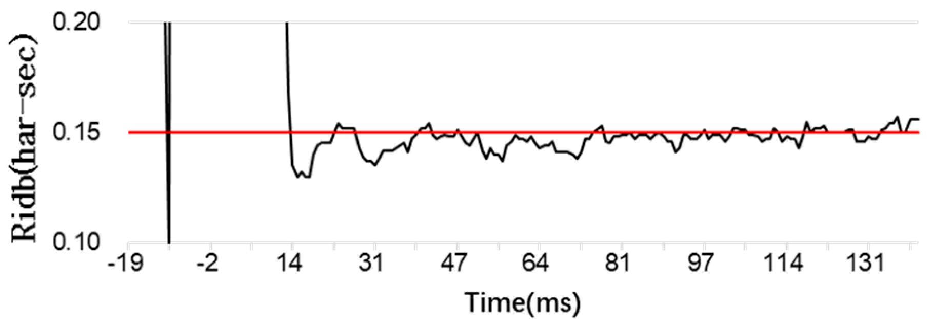
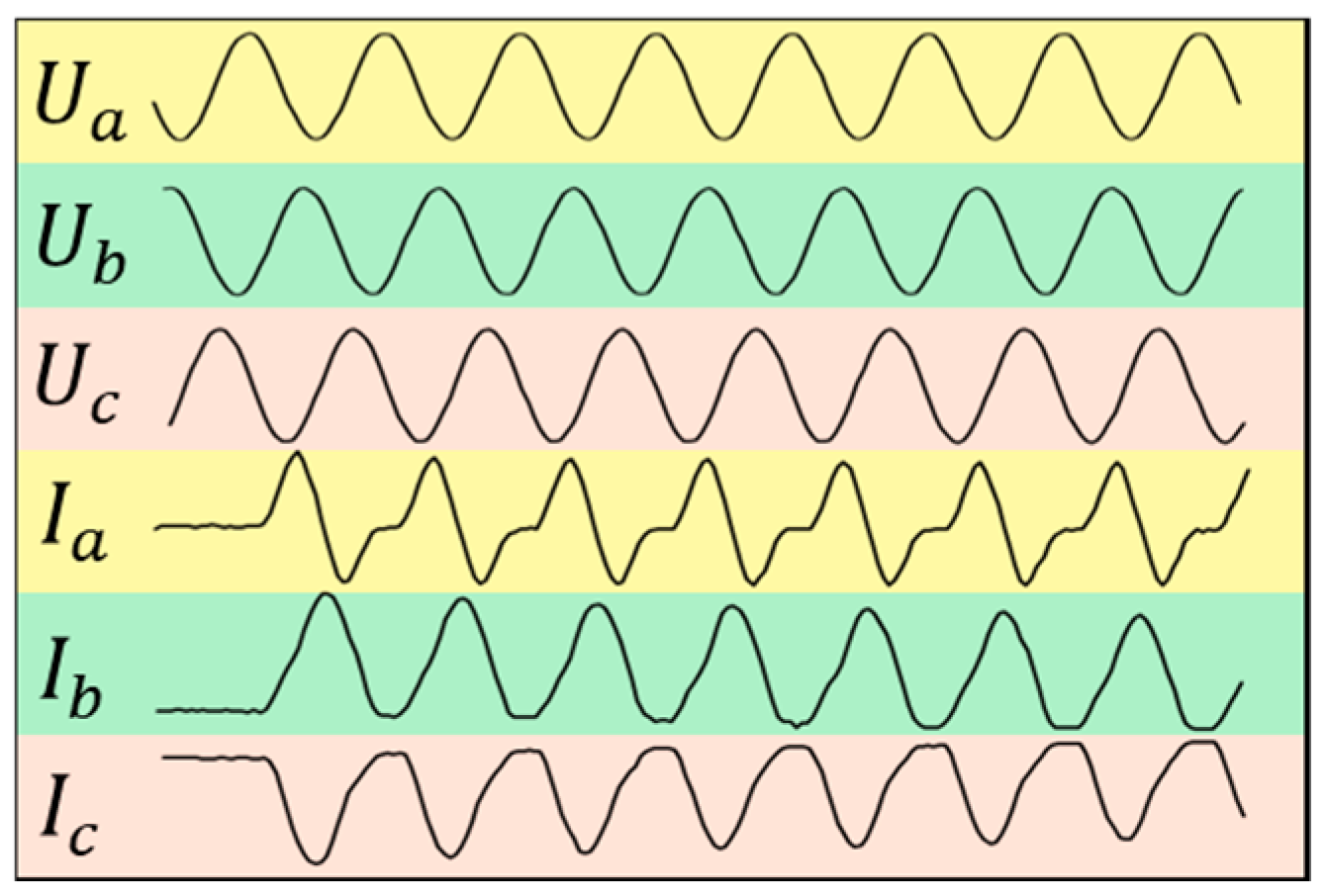
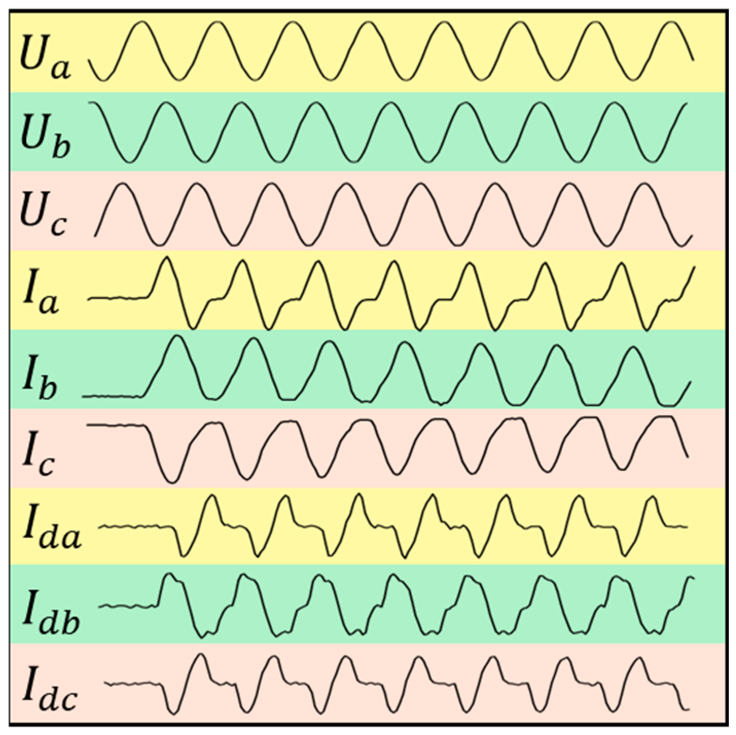
This case study from a field application presents an analysis of a 120 MVA/220 kV power transformer during no-load energization, and the waveforms of current, voltage, and differential current are shown in Figure 8. The harmonic content of the B-phase differential current is shown in Figure 9. The B-phase differential current waveform analysis reveals concurrent failures in both the waveform symmetry criterion and interrupted-angle principle, as clearly demonstrated in the recorded waveforms. At the same time, through the analysis of the harmonic content, the second-harmonic ratio of the B-phase differential current repeatedly falls below the 15% threshold. The second-harmonic restraint principle fails when the harmonic content falls below the threshold, causing differential protection misoperation. This reveals inherent limitations in conventional engineering identification methods.

3. Data Curation Strategy

3.1. Instrument Transformer Configuration

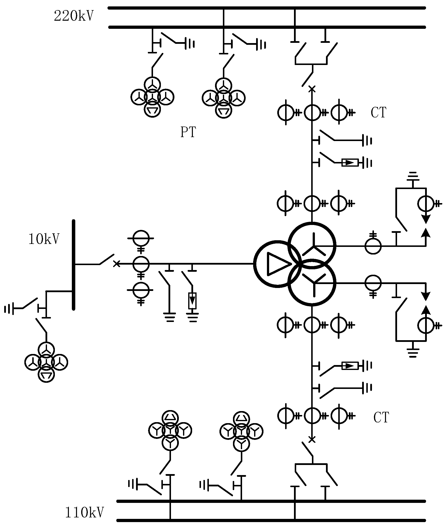
In a typical 220 kV substation configuration (as illustrated in Figure 10), the main instrument transformer is equipped with voltage transformers (VTs) installed at the busbar and current transformers (CTs) positioned at the circuit breakers. Analysis of the primary single-line diagram reveals that the transformer protection system acquires three-phase current measurements from each circuit breaker location on both sides of the transformer, along with three-phase voltage measurements from the connected busbar, thereby enabling comprehensive monitoring and protection functionality.
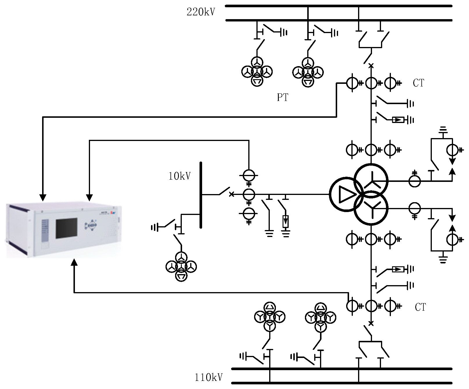
Transformer protection systems are typically categorized into primary and backup protection schemes. The primary protection primarily employs differential protection, while the backup protection incorporates overcurrent protection, zero-sequence overcurrent protection, and other complementary protective elements. As depicted in Figure 11, transformer core saturation results in reduced magnetizing impedance, consequently increasing the magnetizing current. This phenomenon may potentially lead to the misoperation of the differential protection system due to the altered magnetic characteristics.

3.2. Design of Data Scheme

Transformer magnetizing inrush currents manifest in three primary scenarios: (1) no-load switching conditions, (2) system voltage recovery following fault clearance, and (3) operations involving series/parallel transformer configurations. In the case of no-load switching, the transformer protection device can obtain the three-phase voltage and three-phase current on the switching side. During post-fault voltage restoration, the transformer protection device can obtain the three-phase voltage and three-phase current on each side of the transformer. Similarly, in the case of magnetizing inrush current generated by series and parallel transformers, the transformer protection device can also obtain the three-phase voltage and three-phase current on each side of the transformer.
The magnetizing inrush current primarily compromises differential protection reliability. However, inrush identification becomes unnecessary when the differential current remains below the protection operating threshold. Consequently, magnetizing inrush current identification is only necessary when the differential current exceeds significant magnitudes. This necessitates that protection schemes account for differential current characteristics in transformer applications. Furthermore, since the differential current derives from linear combinations of winding currents, inherent information redundancy exists between the differential quantity and individual winding measurements.
To minimize computational burden, the protection scheme should avoid simultaneous utilization of both differential current and individual winding current measurements. Core saturation phenomena significantly reduce transformer magnetizing impedance, which can only be accurately characterized through combined voltage and current measurements. Consequently, effective identification algorithms must incorporate both voltage and current information for reliable operation.
To address diverse magnetizing inrush conditions while avoiding information redundancy, we propose two distinct identification schemes. The first scheme utilizes three-phase voltage and current measurements from a single transformer winding, with each winding providing independent identification data (Figure 12). While this approach captures complete electrical signatures during no-load switching operations, it omits current information from non-measured windings during other inrush scenarios.
The second scheme incorporates three-phase voltage, current, and differential current measurements from a single winding (Figure 13). While this configuration introduces measurement redundancy during no-load switching (where phase currents and differential currents become equivalent), it provides complete winding current information during other inrush conditions.
Since the identification scheme cannot anticipate the transformer’s operational state during inrush events (which may include no-load switching or other conditions), this work adopts scheme 2 for enhanced practicality. The selected configuration employs single-winding three-phase voltage, current, and differential current measurements, providing comprehensive electrical information across all inrush scenarios while maintaining implementation feasibility.

4. Design of Identification Model

Transformer magnetizing inrush identification requires binary classification of voltage/current waveform characteristics from fault recordings—a multivariate classification problem. This section analyzes typical CNN architectures for classification, with Table 1 comparing their merits and limitations.
t-LeNet [21], an adaptation of the classical LeNet architecture for time-series analysis, comprises two convolutional layers, two pooling layers, and one fully connected layer (Figure 14). The model offers computational efficiency through its lightweight structure, enabling rapid convergence for simple waveforms. However, its limited capacity for hierarchical feature extraction results in suboptimal accuracy when processing complex time-series patterns in practical implementations.
The Fully Convolutional Network (FCN) [22] replaces fully connected layers with global pooling, enabling variable-size input processing (Figure 15). This architecture maintains channel-wise information while reducing dimensionality through global pooling operations. However, FCNs exhibit training instability due to gradient vanishing/explosion phenomena, often resulting in convergence challenges.
The Temporal Convolutional Network (TCN) [23] integrates causal and dilated convolutions to efficiently expand the receptive field (Figure 16). This architecture enhances long-term dependency modeling in time-series data while maintaining computational efficiency. However, TCN implementations face practical challenges including structural complexity, sensitive hyperparameter requirements, and consequent training/optimization difficulties that hinder deployment scalability.
ResNet [24] addresses gradient vanishing/explosion issues in deep neural networks through residual learning (Figure 17). The architecture’s residual blocks demonstrate strong feature extraction capabilities for transformer magnetizing inrush current analysis, achieving superior recognition accuracy. The residual connections enhance training stability and accelerate convergence while maintaining architectural flexibility for task-specific adaptation.
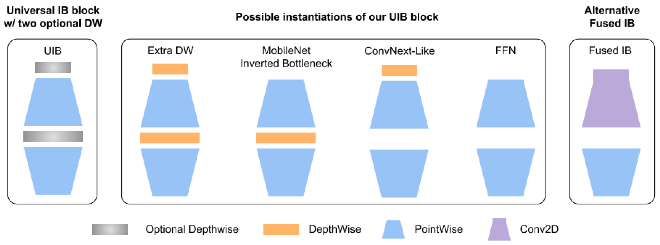
MNv4 [25] unifies convolutional and attention computations via its Universal Inverted Bottleneck (UIB) module (Figure 18), significantly simplifying architectural design. The UIB dynamically switches between local convolution and global attention modes. Multi-Query Attention (MQA) and Hard Swish activation functions ensure balanced performance and energy efficiency. Serving as a universal backbone network, this architecture adapts to mobile-edge vision tasks including object detection and segmentation. It establishes a major breakthrough in speed-accuracy tradeoffs for lightweight models.
Based on architectural trade-off analysis, this work selects MNv4 for transformer magnetizing inrush current classification. Relay protection devices, as embedded systems with constrained resources, require low-parameter and high-efficiency models as optimal solutions. MNv4 features universally efficient architecture designs for mobile devices. MNv4’s training stability and structural flexibility effectively process complex time-frequency characteristics in inrush currents.

5. Experimental Validation of the Proposed Methodology

5.1. Dataset Generation

To overcome the scarcity of practical magnetizing inrush current data for model training, this paper establishes a transformer simulation model in the electromagnetic transient simulation software PSCAD4.5 to generate the required data. The simulation system is shown in Figure 19. Transformer T1 (220 kV/110 kV, 200 MVA, 50 Hz, 0.16 p.u. leakage reactance) serves as the primary unit, with identical T2 for parallel/series operation studies. The system includes five fault points (F1–F5) and corresponding circuit breakers (QF1–QF5). Transformer T3 (110 kV/10 kV, 90 MVA, 50 Hz, 0.28 p.u. leakage reactance) completes the test configuration.
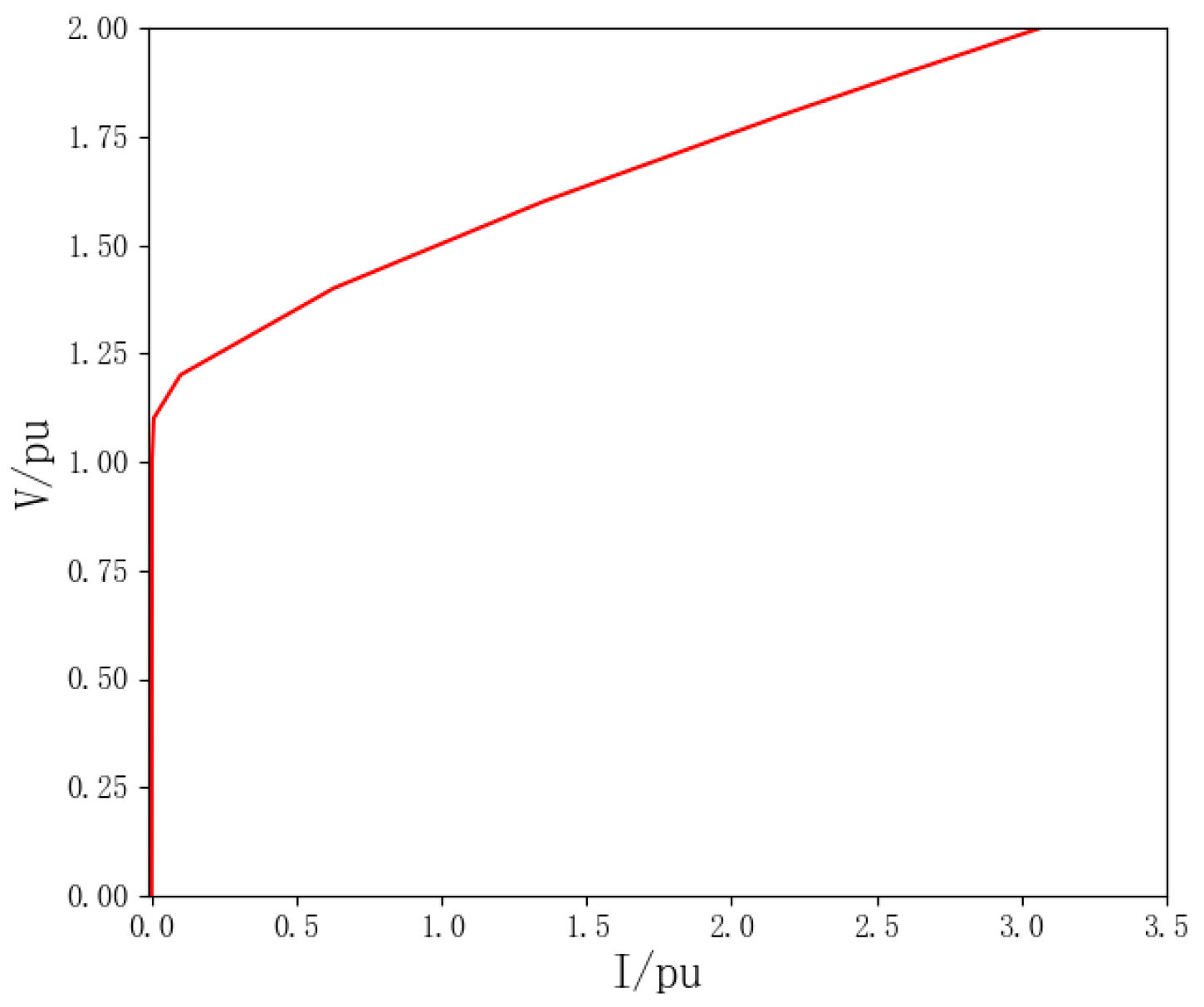
Figure 20 presents the magnetization curve of Transformer T1 implemented in the simulation. This curve, derived from actual engineering measurements of the transformer’s current-voltage characteristics, demonstrates close alignment with theoretical magnetization behavior and accurately represents the core’s magnetic properties. The adopted curve ensures realistic simulation of the transformer’s operational conditions.
The simulation investigates multiple electromagnetic transient scenarios: (1) magnetizing inrush during no-load switching, (2) voltage recovery inrush post-fault clearance, (3) coupled inrush phenomena in series/parallel transformer configurations, and (4) internal/external zone faults (including symmetrical/asymmetrical types). The three scenarios (scenarios 1 to 3) investigate transformer transient behavior under a variety of conditions, encompassing different levels of core remanent flux, switching instants (closing angles), and fault initiation points (fault inception angles). Field-recorded data supplements synthetic results to form a 3040-sample dataset (1680 inrush vs. 1360 non-inrush cases), stored in COMTRADE format with 9 channel measurements per sample. Binary labeling (0: steady-state/normal fault, 1: inrush condition) accompanies each record. A stratified 5:2:3 ratio partitions the dataset into training, validation, and testing subsets.

5.2. Model Training

For CNN-based fault recording analysis, the COMTRADE-format data underwent preprocessing via Python 3.9-based parsing and subsequent conversion to inputs for model training/testing. The PyTorch (2.8.0) framework implemented all deep learning architectures, with computational experiments executed on a workstation featuring dual Intel Xeon Gold 6248R CPUs and an NVIDIA RTX 3090 GPU.
The cross-entropy loss function was employed for model optimization, defined as
L y , y ^ = y log ( y ^ ) + ( 1 y ) log ( 1 y ^ )
The classification model’s final layer utilized log-softmax activation to transform fully connected layer outputs into logarithmic probabilities, enhancing numerical stability during cross-entropy loss computation and mitigating Softmax-induced overflow risks. Early stopping regularization terminated training when validation loss plateaued across consecutive epochs. Hyperparameter configurations are specified in Table 2.

5.3. Model Verification Results

Six classification algorithms (DTW-kNN, MLP, t-LeNet, FCN, TCN and ResNet [11]) were compared with the MNv4 model. DTW-kNN served as the machine learning benchmark, MLP as a baseline neural network, and the remaining four as CNN variants. Four metrics evaluated performance: (1) accuracy (overall prediction correctness), (2) precision (positive-class prediction reliability, reducing false positives), (3) recall (positive-class detection capability, minimizing false negatives), and (4) F1-score (harmonic mean of precision/recall for balanced assessment). Formal metric definitions appear in Equation (6) and Table 3.
Accuracy = TP + TN / TP + TN + FP + FN Precision = TP / TP + FP Recall = TP / TP + FN F 1 = 2 × Precision × Recall / Precision + Recall
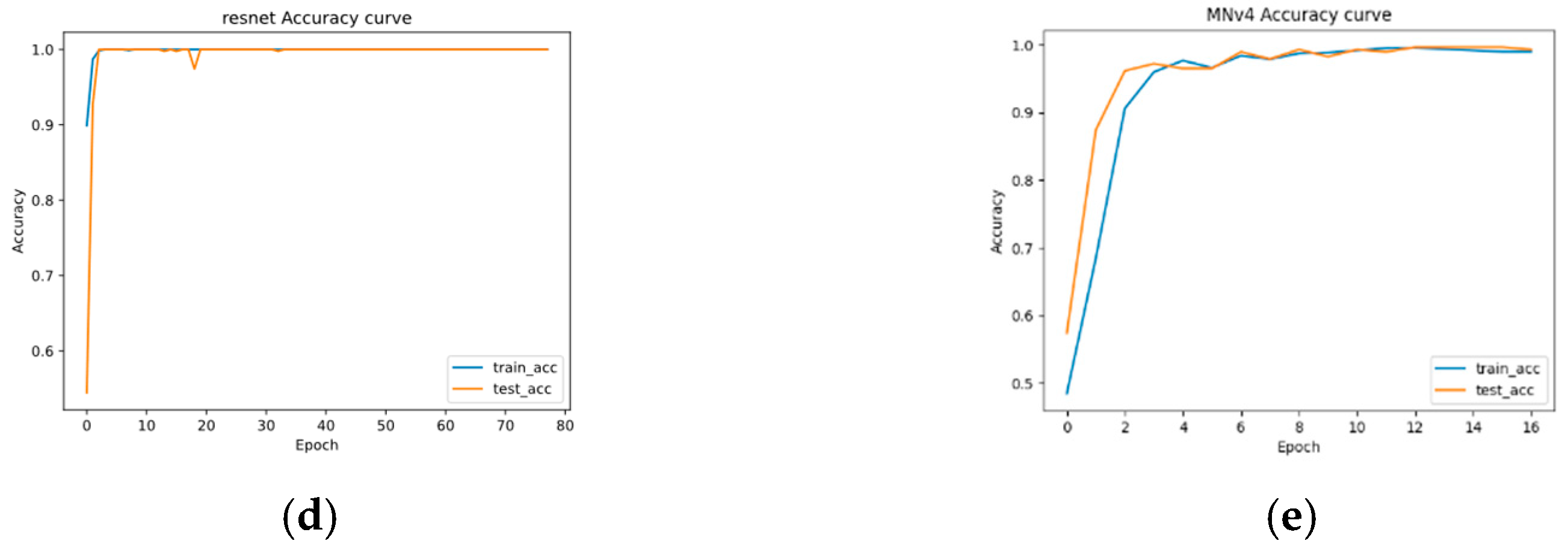
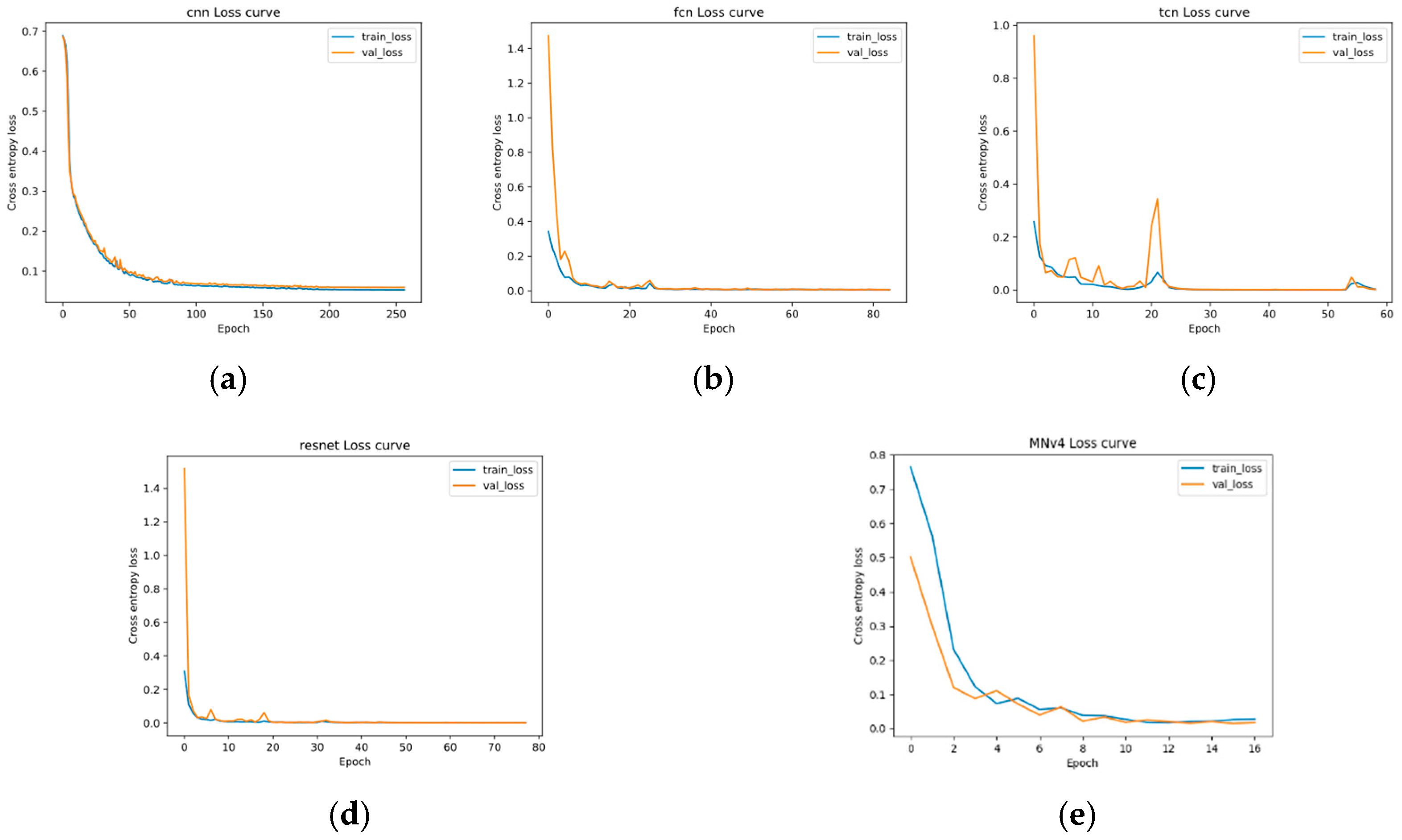
The comparative performance of the seven classification algorithms is presented in Table 4. Figure 21 and Figure 22 show the trends of the classification accuracy curves and the loss function curves during the training process of the four convolutional neural networks, respectively. Table 4 demonstrates that all the machine learning models achieved satisfactory classification performance in the task of magnetizing inrush current identification, with MNv4 exhibiting superior computational efficiency. The accuracy and loss function curves reveal that t-LeNet has the slowest convergence, requiring about 250 epochs of training. MNv4 only needs more than ten epochs to converge, and the training process is relatively stable.
To further reduce the model parameters and increase inference speed, this paper introduces additional optimizations to MNv4 by pruning the original eight IB layers to three different configurations: two, four, and six IB layers. The performance of the models under these optimizations was analyzed, as shown in Figure 23 and Figure 24. It can be observed that the model with two IB layers already met the requirements. Therefore, the final architecture was optimized from the configuration in Table 5 to that in Table 6, resulting in a model termed MNv4-Light.

6. Conclusions

This paper systematically investigates magnetizing inrush current generation mechanisms and their effects on transformer protection systems. Utilizing PSCAD electromagnetic transient simulations and field measurements, we constructed a dataset containing thousands of inrush current samples. The study introduces a novel identification framework and conducts rigorous comparative analysis of multiple artificial intelligence algorithms’ performance.
This study demonstrates the successful application of artificial intelligence algorithms for transformer magnetizing inrush current identification, achieving superior performance compared to conventional methods. The proposed method significantly enhances transformer protection adaptability in high-harmonic environments of modern sustainable power systems. It effectively improves protection reliability and sensitivity. The proposed approach not only validates the technical feasibility of AI-based solutions in power system protection but also establishes a systematic framework for future research in this domain. These findings contribute valuable insights for implementing intelligent relay protection systems in modern power systems.

Author Contributions

Methodology, W.X.; software, Y.X.; formal analysis, W.X.; investigation, Z.Y.; data curation, Q.C.; writing—original draft preparation, W.X.; writing—review and editing, Z.L., Y.X., M.X., Z.Y. and Q.C.; project administration, M.X. All authors have read and agreed to the published version of the manuscript.

Funding

This research received no external funding.

Institutional Review Board Statement

Not applicable.

Informed Consent Statement

Not applicable.

Data Availability Statement

The data presented in this study are available on request from the corresponding author.

Conflicts of Interest

Authors Wu Xing, Mingjun Xue, Ziheng Yan, Yang Xiao and Qi Chen were employed by Guodian Nanjing Automation Co., Ltd. Authors Wu Xing, Mingjun Xue, Ziheng Yan, Yang Xiao and Qi Chen were employed by Nanjing SAC Automation Co., Ltd. The remaining authors declare that the research was conducted in the absence of any commercial or financial relationships that could be construed as a potential conflict of interest.

References

  1. Zhang, B.; Yin, X. Power System Protective Relaying; China Electric Power Press: Beijing, China, 2000. [Google Scholar]
  2. Wang, Y.; Xu, Z. Inrush current suppression strategy of three-phase transformer based on combined-switches. Electr. Power Autom. Equip. 2019, 39, 99–106. [Google Scholar]
  3. Jiao, Z.; Xing, W.; Wang, Z.; Jin, J. Features and Mechanism of Negative-sequenee Second Harmonics of Magnetizing Inrush Current in Transformers. Autom. Electr. Power Syst. 2015, 39, 146–151. [Google Scholar]
  4. Guo, C.; Yan, C.; Wu, H. Influence of Transformer Excitation Surge on Adjacent Generator and Solutions. Transformer 2023, 60, 28–30. [Google Scholar]
  5. Huang, D.; Yan, B.; Shen, C.; Zheng, G.; Lin, J.; Chen, C. A Novel Inrush Current Distinguishing Scheme Based on Second harmonic Component Decaying Characteristics of Transformer Current. Transformer 2023, 60, 28–34. [Google Scholar]
  6. Zhang, S.; Sun, Q.; Zhang, H.; Wang, M. Identification of information entropy in transformer inrush current. Power Syst. Prot. Control 2017, 45, 107–111. [Google Scholar]
  7. Li, B.; Peng, W.; Yao, B.; Fan, L.; Li, P.; Wang, X.; Du, Z.; Key Laboratory of Smart Grid of Ministry of Education (Tianjin University); China Electric Power Research Institute; State Grid Hubei Electric Power Research Institute. An Algorithm of Identifying Inrush Current of Converter Transformer Based on Waveform Cross-correlation of Composite Circulation and Zero Sequence Current Characteristics. Proc. CSEE 2020, 40, 8027–8039. [Google Scholar]
  8. Li, G.; Wang, J.; Tang, Q.; Zhang, Y.; Liu, S. Automatic identification method for excitation inrush current in power transformers based on wavelet theory. Electron. Des. Eng. 2024, 32, 31–35. [Google Scholar]
  9. Afrasiabi, S.; Afrasiabi, M.; Parang, B.; Mohammadi, M. Designing a composite deep learning based differential protection scheme of power transformers. Appl. Soft Comput. 2020, 87, 105975. [Google Scholar] [CrossRef]
  10. Afrasiabi, S.; Afrasiabi, M.; Parang, B.; Mohammadi, M.; Samet, H.; Dragicevic, T. Fast GRNN-based method for distinguishing inrush currents in power transformers. IEEE Trans. Ind. Electron. 2021, 69, 8501–8512. [Google Scholar] [CrossRef]
  11. Zhang, G.; Liu, K.; Pu, H.; Yao, F.; Zhang, S. Identification of Inrush Current and Fault Current Based on Long Short-Term Memory Neural Network. J. Shanghai Jiao Tong Univ. 2024, 58, 730–738. [Google Scholar]
  12. Li, Z.; Liu, F.; Yang, W.; Peng, S.; Zhou, J. A survey of convolutional neural networks: Analysis, applications, and prospects. IEEE Trans. Neural Netw. Learn. Syst. 2021, 33, 6999–7019. [Google Scholar] [CrossRef] [PubMed]
  13. Afrasiabi, S.; Afrasiabi, M.; Parang, B.; Mohammadi, M. Integration of accelerated deep neural network into power transformer differential protection. IEEE Trans. Ind. Inform. 2019, 16, 865–876. [Google Scholar] [CrossRef]
  14. He, A.; Jiao, Z.; Li, Z.; Liang, Y. Discrimination between internal faults and inrush currents in power transformers based on the discriminative-feature-focused CNN. Electr. Power Syst. Res. 2023, 223, 109701. [Google Scholar] [CrossRef]
  15. Atiyah, W.A.; Karimi, S.; Moradi, M. A novel approach for diagnosing transformer internal defects and inrush current based on 1DCNN and LSTM deep learning. J. Electr. Syst. 2024, 20, 2557–2572. [Google Scholar] [CrossRef]
  16. Xu, Y. Analysis and Research of the Transformer Inrush Current and the Sympathetic Inrush Current; North China Electric Power University: Beijing, China, 2008. [Google Scholar]
  17. Jin, E.; Sun, S.; Qi, Z.; Wu, Y. A new algorithm to prevent the mal-operation of transformer differential protection after removing external fault. Power Syst. Prot. Control 2011, 39, 27–30. [Google Scholar]
  18. Wu, W.; Bian, J.; Wu, Z. Principle and characteristics Of transformer sympathetic inrush. Electr. Power Autom. Equip. 2011, 31, 112–115. [Google Scholar]
  19. Wu, P.; Yu, X.; Li, Y.; Wang, T. Engineering application of transformer excitation inrush suppressor. Electr. Power Autom. Equip. 2012, 32, 145–149. [Google Scholar]
  20. Liu, Y.; Zhang, J.; Lu, H.; Lan, L. Excitation Inrush Current Test and Simulation Analysis of Transformer in No-load closing Switching. High Volt. Appar. 2017, 53, 117–123. [Google Scholar]
  21. Le Guennec, A.; Malinowski, S.; Tavenard, R. Data augmentation for time series classification using convolutional neural networks. In Proceedings of the ECML/PKDD Workshop on Advanced Analytics and Learning on Temporal Data, Riva Del Garda, Italy, 19 September 2016. [Google Scholar]
  22. Wang, Z.; Yan, W.; Oates, T. Time series classification from scratch with deep neural networks: A strong baseline. In Proceedings of the 2017 International Joint Conference on Neural Networks (IJCNN), Anchorage, AK, USA, 14–19 May 2017; pp. 1578–1585. [Google Scholar]
  23. Bai, S.; Kolter, J.Z.; Koltun, V. An empirical evaluation of generic convolutional and recurrent networks for sequence modeling. arXiv 2018, arXiv:1803.01271. [Google Scholar] [CrossRef]
  24. Ismail Fawaz, H.; Forestier, G.; Weber, J.; Idoumghar, L.; Muller, P.-A. Deep learning for time series classification: A review. Data Min. Knowl. Discov. 2019, 33, 917–963. [Google Scholar] [CrossRef]
  25. Qin, D.; Leichner, C.; Delakis, M.; Fornoni, M.; Luo, S.; Yang, F.; Wang, W.; Banbury, C.; Ye, C.; Akin, B.; et al. MobileNetV4: Universal Models for the Mobile Ecosystem. arXiv 2024, arXiv:2404.10518v2. [Google Scholar]
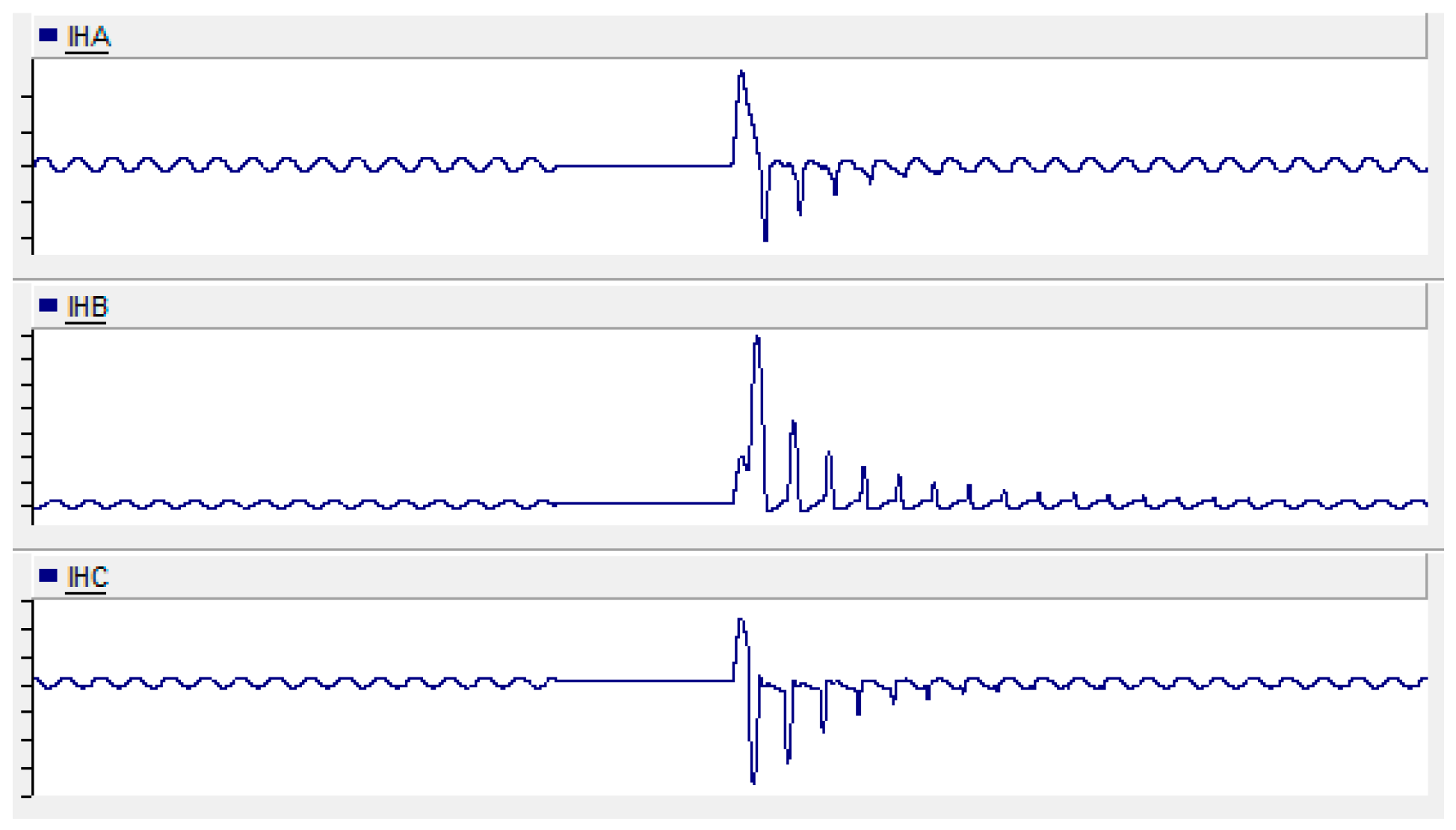
Figure 1. Recovery magnetizing inrush current waveform.
Sustainability 17 10502 g001
Figure 2. No-load closing magnetizing inrush current waveform.
Sustainability 17 10502 g002
Figure 3. Resonant inrush current (or sympathetic inrush) waveform.
Sustainability 17 10502 g003
Figure 4. Equivalent circuit of single-phase transformer during no-load switching.
Sustainability 17 10502 g004
Figure 5. Approximate magnetization curve of transformer.
Sustainability 17 10502 g005
Figure 6. Waveform diagram of flux and excitation current.
Sustainability 17 10502 g006
Figure 7. Equivalent circuit of single-phase transformer.
Sustainability 17 10502 g007
Figure 8. Waveforms of current, voltage, and differential current during no-load switching. (a) Current waveforms. (b) Voltage waveforms. (c) Differential current waveforms.
Sustainability 17 10502 g008
Figure 9. Harmonic content analysis chart.
Sustainability 17 10502 g009
Figure 10. Instrument transformer configuration diagram.
Sustainability 17 10502 g010
Figure 11. Schematic diagram of current collected by differential protection.
Sustainability 17 10502 g011
Figure 12. Schematic diagram of Identification scheme 1.
Sustainability 17 10502 g012
Figure 13. Schematic diagram of Identification scheme 2.
Sustainability 17 10502 g013
Figure 14. t-LeNet Network structure.
Sustainability 17 10502 g014
Figure 15. Fully Convolutional Network structure.
Sustainability 17 10502 g015
Figure 16. Temporal Convolutional Network structure.
Sustainability 17 10502 g016
Figure 17. Residual Network structure.
Sustainability 17 10502 g017
Figure 18. Universal Inverted Bottleneck (UIB) blocks.
Sustainability 17 10502 g018
Figure 19. Simulation system diagram.
Sustainability 17 10502 g019
Figure 20. Magnetization curve.
Sustainability 17 10502 g020
Figure 21. Classification accuracy curves. (a) t–LeNet; (b) FCN; (c) TCN; (d) ResNet; (e) MNv4.
Sustainability 17 10502 g021aSustainability 17 10502 g021b
Figure 22. Loss function curves. (a) t–LeNet; (b) FCN; (c) TCN; (d) ResNet; (e) MNv4.
Sustainability 17 10502 g022
Figure 23. Classification accuracy curves of different architectures. (a) MNv4-2IB; (b) MNv4-4IB; (c) MNv4-6IB.
Sustainability 17 10502 g023
Figure 24. Loss function curves of different architectures. (a) MNv4-2IB; (b) MNv4-4IB; (c) MNv4-6IB.
Sustainability 17 10502 g024
Table 1. Comparative analysis of convolutional neural network.
Classification ModelAdvantagesDisadvantages
t-LeNetSimple structure, easy to convergePoor feature extraction ability
FCNFewer parametersDifficult to train, hard to converge
TCNCan learn long-term scale dependenciesComplex structure, difficult to converge
ResNetStable training, easy to convergeLonger inference time
MNv4Low latency, fewer parameters, universally efficient architecture designs for mobile devicesSlightly lower accuracy
Table 2. Hyperparameter configuration of the classification model.
Hyperparameter NameValue
Activation FunctionReLU
Learning Rate3 × 10−4
Batch Size16
Maximum Number of Epochs500
Early Stopping Threshold10
Weight Decay0.01
Table 3. Confusion matrix.
Predicted ValueActual Value
Positive SampleNegative Sample
Positive SampleTPFP
Negative SampleFNTN
Table 4. Comparison of classification metrics.
ModelAccuracyPrecisionRecallF1-Score
DTW-kNN0.9880.9890.9880.988
MLP0.9870.9870.9870.987
t-LeNet0.9900.9900.9900.990
FCN0.9940.9940.9940.994
TCN0.9920.9920.9920.992
ResNet0.9980.9980.9980.998
MNv40.9970.9970.9970.997
Table 5. Architecture specification of mnv4-conv-s.
InputBlockDW K1DW K2Expanded DimOutput DimStride
2242 × 3Conv2D-3 × 3-322
1122 × 32FusedIB-3 × 332322
562 × 32FusedIB-3 × 396642
282 × 64ExtraDW5 × 55 × 5192962
142 × 96IB-3 × 3192961
142 × 96ConvNext3 × 3-384961
142 × 96ExtraDW3 × 33 × 35761282
72 × 128ExtraDW5 × 55 × 55121281
72 × 128IB-5 × 55121281
72 × 128IB-5 × 53841281
72 × 128IB-3 × 35121281
72 × 128AvgPool-1 × 1-1281
12 × 128Conv2D-1 × 1-21
Table 6. Architecture specification of mnv4—light.
InputBlockDW K1DW K2Expanded DimOutput DimStride
2242 × 3Conv2D-3 × 3-322
1122 × 32FusedIB-3 × 332322
562 × 32FusedIB-3 × 396642
282 × 64ExtraDW5 × 55 × 5192962
142 × 96IB-3 × 3192961
142 × 96ConvNext3 × 3-384961
142 × 96ExtraDW3 × 33 × 35761282
72 × 128ExtraDW5 × 55 × 55121281
72 × 128IB-5 × 55121281
72 × 128AvgPool-1 × 1-1281
12 × 128Conv2D-1 × 1-21
Disclaimer/Publisher’s Note: The statements, opinions and data contained in all publications are solely those of the individual author(s) and contributor(s) and not of MDPI and/or the editor(s). MDPI and/or the editor(s) disclaim responsibility for any injury to people or property resulting from any ideas, methods, instructions or products referred to in the content.