Article

Mining-Induced Permeability Evolution of Inclined Floor Strata and In Situ Protection of Confined Aquifers

by
Zhanglei Fan
1,
Gangwei Fan
1,2,*,
Dongsheng Zhang
1,
Tao Luo
1,
Congxin Yang
1,
Xinyao Gao
1 and
Zihan Kong
1
1
School of Mines, China University of Mining and Technology, Xuzhou 221116, China
2
Yunlong Lake Laboratory of Deep Earth Science and Engineering, Xuzhou 221116, China
*
Author to whom correspondence should be addressed.
Sustainability 2025, 17(22), 10273; https://doi.org/10.3390/su172210273
Submission received: 27 September 2025 / Revised: 29 October 2025 / Accepted: 14 November 2025 / Published: 17 November 2025

Abstract

Mining above confined aquifers fundamentally depends on understanding the evolution of floor permeability for water hazard control and water conservation mining. A mechanical model was developed to characterize the coordinated deformation of floor aquiclude strata, accounting for non-uniform distributions of stress and water pressure. The competing mechanisms whereby neutral plane strain and flexural deflection dominantly control permeability at different dip angles were elucidated, and the influence of dip angle on the stability of the water-resistant key strata was quantified. On this basis, a quantitative method for assessing the feasibility of in situ water conservation mining above confined aquifers was developed and its effectiveness was verified through field application. The main findings are as follows: The deflection of the floor aquiclude increases with water pressure, advance distance, and panel length. Larger coal seam dip angles correspond to smaller aquiclude deflection, with a strong dependence on the water pressure treatment method. The equivalent permeability of the floor increases with water pressure, panel length, and advance distance, and its variation is most pronounced with water pressure. As the dip angle increases, the equivalent permeability exhibits a trend of first rising and then decreasing; the transition between deflection-dominated and neutral plane strain-dominated control occurs at a dip angle of 35°. Lithological assemblage is found to govern the position of the neutral plane and the bending stiffness matrix, while a soft–hard interbedded floor is effective in suppressing deformation and mitigating the increase in the equivalent permeability. For inclined aquiclude key strata, the ranking of zones most prone to failure and water inrush is as follows: lower end > upper end > coal wall position > behind the goaf. A quadratic multi-parameter response model for the mining-induced equivalent permeability at the Fenyuan Coal Mine is established, yielding the sensitivity ranking under single factor and interaction effects as follows: water pressure > panel length > advance distance > water pressure (quadratic) > water pressure × panel length interaction. The higher the water pressure, the stronger the influence of dip angle on the equivalent permeability. Groundwater ion evolution is dominated by dissolution/leaching, with sulfate (SO42−) serving as a diagnostic ion for source identification. The stepwise criteria and grouting-reinforcement parameters for in situ protection of confined aquifers are proposed. Using water quality and quantity as evaluation metrics, Working Face 5-103 at the Fenyuan Coal Mine, which is a large-inclination-angle and high-pressure working face, has achieved in situ protection of the floor water.

1. Introduction

Coal mining above the Ordovician limestone aquifer is widespread in the Yellow River Basin of China. The Ordovician aquifer is both valuable and widely used, and it maintains close hydraulic connectivity with the Yellow River and its tributaries [1]. Floor damage induced by mining can establish pathways to this aquifer, leading to groundwater loss, water quality degradation, and even catastrophic water inrush; more than 40% of coal resources are threatened, with approximately 230 mines affected in North China alone [2]. Tectonic deformation has led to a further concentration of steeply dipping confined coal seams in the Huang-Huai-Hai region, where coal reserves exceed 14 billion tons, notably in the Yimeng Uplift of the Ordos Basin, the Ningwu Fold Belt in Shanxi, and the Huafeng Anticline in Shandong, featuring seam dips of 20–60° and local water pressures up to 8.2 MPa. Water conservation mining is a key approach to implementing green coal resource extraction, ensuring high-level ecological and environmental protection, and advancing national sustainable development. As a vital ecological barrier in China, the Yellow River basin has suffered from a series of ecological damages such as accelerated soil erosion and water resource depletion due to coal mining activities. It is imperative to pursue water conservation mining practices to achieve both safety and environmental sustainability. Clarifying the permeability behavior of the mining floor under large inclination angles and high water pressure and achieving in situ protection of confined aquifers during mining are urgent technical challenges for implementing Yellow River Basin water resource protection in the coal sector [3].
Extensive research on water inrush mechanisms and prevention for horizontal coal seams overlying confined aquifers has evolved from considering a single confined aquifer to composite confined aquifer systems [4], and from intact floors to floors containing geological anomalies (faults, collapse columns, crushed zones, etc.). This progression has yielded the downward three-zone theory [5], the water-resistant key strata theory [6], the water inrush coefficient method [7], and the systemic non-linear entropy change theory [8]. Building on these frameworks, a suite of exploration, monitoring, early warning, and control techniques, such as dewatering and depressurization, underground grouting-based modification and reinforcement, and surface regional treatment, has been proposed and effectively applied to ensure mine safety [9,10,11,12]. However, because the primary objective of conventional water inrush control is to secure the safe retreat of the working face, indicators such as floor inflow and water quality are often overlooked. For example, although grouting reinforcement at the Longquan Mine satisfied the criteria for safe pressurized mining, the working face still experienced inflows up to 150 m3/h, resulting in substantial waste of groundwater resources. There is thus a pressing need to shift the paradigm from control to in situ protection of floor confined water, that is, to treat floor water hazard control and in situ protection of floor water as complementary goals.
Under large-inclination-angle conditions, the mining floor exhibits pronounced asymmetric stress unloading, which heightens the likelihood of water inrush [13]. As the primary factor governing the dynamic behavior of mining-inclined coal and rock masses, the roof and floor loads and high water pressure no longer distribute uniformly due to varying working face depths. This significantly impacts roof structure configuration, mining stress conditions, floor slippage, and structural differentiation [14,15,16]. Classical elastic half-space theory together with thin- and moderately thick-plate theories are commonly employed to analyze floor failure depth, fracture patterns, and the stability of water-resistant key strata [17,18]. These studies show that dip angle leads to a greater failure depth at the lower end of the floor, that failure depth is positively correlated with water pressure, and that different dip angles elicit distinct unloading responses in the floor stress state [19]. Moreover, high water pressure promotes the diffusion of horizontal stress and reduces the floor rock’s shear resistance, thereby intensifying floor fracturing [20]. The theoretical framework and assumptions employed in the stability analysis of the water-resistant strata are presented in Table 1. Collectively, the asymmetric unloading associated with steeply inclined seams poses new challenges to in situ protection of high-pressure confined water in the floor during mining.
Mining-induced permeability is a pivotal parameter for water hazard risk assessment and for evaluating the feasibility of water conservation mining [21]. Traditional indices derived from empirical or mechanical analyses, such as floor failure depth and aquiclude stability, primarily appraise the water-resistant capacity of a single or composite stratum, but they do not fully capture the overall water-resistant capability of the mined floor system [22]. In practice, mining-induced hydraulic conductivity is tightly coupled to floor failure characteristics and emerges from the interaction of geological conditions, hydrogeological setting, and mining activities. Current approaches to characterizing overburden/floor permeability include the following: (i) Strata subsidence theory [23], which uses the ratio of separation to overlying thickness to indicate porosity; this requires differential deflection among layers and neglects lithologic variation. (ii) Recursive (modified strata subsidence theory) functions [24], which assume an expanding influence radius and introduce lithologic contrasts, but still overlook interlayer separation. (iii) Permeability (hydraulic conductivity) theoretical models [25], which relate permeability to mining-induced stress/strain or employ discrete fracture-network formulations, and which are one of the most widely used families of methods. Zhou et al. reviewed mining-induced permeability characterization, applicable ranges, and future directions [26]. Wu, Xu et al. integrated geologic, hydrogeologic, and mining factors to propose floor water-resistant performance evaluations based on the vulnerability index and the water inrush coefficient [27,28]. Zhao et al. analyzed aquifer pore pressure responses and asymptotic drawdown behavior with and without faults [29]. Despite these advances, the equivalent hydraulic conductivity of the floor during mining of inclined seams above confined water remains to be further clarified.
Building on the load-bearing characteristics of the mining floor under steep dip and high water pressure, we develop a cooperative deformation mechanical model for a floor aquiclude assemblage subjected to non-uniform stress and water pressure distributions; quantify the response of the equivalent hydraulic conductivity to single factor and interaction effects; and propose a quantitative feasibility assessment for the in situ protection of confined water, which is verified through industrial-scale practice. The findings provide a theoretical basis for safeguarding water resources in high-pressure aquifers.

2. Mining-Induced Floor Permeability Evolution Based on Cooperative Deformation of the Aquiclude Assemblage

2.1. Mining-Induced Floor Permeability Model

Mining of steeply inclined coal seams exhibits a pronounced gravity-dip effect [30], under which the loads on the roof and floor and the water pressure become non-uniformly distributed. The non-uniform infilling of caving gangue in the roof further alters the stress state of the floor. Due to the high degree of fragmentation and permeability in the floor failure zone, the rock strata above the aquifer within the failure zone are selected as the study subject. Assuming that different rock layers are homogeneous materials, a composite plate mechanical model for mining-induced impermeable rock layers is established, jointly influenced by confined aquifer water pressure and dip angle. The base of the model is loaded by a linearly distributed water pressure p ( x , y ) , while the upper boundary accounts q ( x , y ) , in a unified manner, for the load contributed by the caving zone and the broken rocks in the floor. The idealized mechanical model is shown in Figure 1.
For the roof, numerous boundary conditions are considered in stability analyses, such as the following: (i) four edges clamped (prior to the first break on the initial panel), (ii) three edges clamped–one edge simply supported (prior to periodic breaking on the initial panel), (iii) adjacent edges clamped–adjacent edges simply supported (prior to the first break with single-side goaf exposure), (iv) opposite edges clamped–opposite edges simply supported (prior to periodic breaking with single-side exposure), and (v) three edges simply supported–one edge clamped (prior to periodic breaking with double-side exposure) [31,32]. By contrast, for the floor aquiclude, the stability problem is typically posed with a single boundary class, four-edge clamped. Unlike the roof, which readily develops structural discontinuities (caving, bed separation), the floor strata under mining influence rarely form fully fractured free boundaries; in engineering practice, their boundaries more closely approximate a rigid restraint, making the clamped condition a better representation of the actual constraints [33,34].
From the standpoint of internal force response, the preference for clamped boundaries also has practical significance for in situ protection of confined floor water. Because rotation and translation are constrained at clamped edges, loading induces larger edge restraining moments and shear forces, which in turn generate higher bending moments and stress concentrations within the plate. Under the same load, the maximum bending moment for a clamped plate is typically >30% higher than that for a simply supported plate, indicating a more intense stress response. Consequently, adopting four-edge clamped boundaries yields conservative estimates and is better suited for field application.
The applied loads are decomposed into components normal to the laminated plate ( q 1 , p 1 ) and parallel to it ( q 2 , p 2 ):
q 1 = γ ( H m 1 H m 1 b y H m 1 H m 2 a x ) cos α q 2 = γ ( H m 1 H m 1 b y H m 1 H m 2 a x ) sin α p 1 = ( P 0 + γ w ( a x ) sin α ) cos α p 2 = ( P 0 + γ w ( a x ) sin α ) sin α
where a and b are the panel length and advance distance, m; γ and γ w are the unit weights of rock and water, N/m3; H m 1 and H m 2 are the heights of the lower and upper fractured zones on the setup-entry side, m; α is the coal seam dip angle, °; P 0 is the water pressure at the upper end of the working face, Pa.
Based on classical laminated plate theory, a laminated plate subjected to external loading undergoes in-plane stretching and bending. Using the stress–strain constitutive law together with the strain–displacement relations, the resultant forces and bending moments can be written as follows [35]:
N x N y N x y = A 11 A 12 0 A 12 A 22 0 0 0 A 66 ε x 0 ε y 0 γ x y 0 + B 11 B 12 0 B 12 B 22 0 0 0 B 66 K x K y K x y M x M y M x y = B 11 B 12 0 B 12 B 22 0 0 0 B 66 ε x 0 ε y 0 γ x y 0 + D 11 D 12 0 D 12 D 22 0 0 0 D 66 K x K y K x y A i j = k = 1 n ( Q ¯ i j ) k ( z k z k 1 ) B i j = 1 2 k = 1 n ( Q ¯ i j ) k ( z k 2 z k 1 2 ) D i j = 1 3 k = 1 n ( Q ¯ i j ) k ( z k 3 z k 1 3 )
where A i j , B i j , and D i j are the extensional, coupling, and bending stiffness matrices, N/m, N, N·m; N x , N y , and N x y are the in-plane resultants per unit width, N; M x , M y , M x y are the bending/twisting moments per unit width, N·m; ε x 0 , ε y 0 , γ x y 0 are the mid-surface strains; K x , K y , K x y are the mid-surface curvatures, m−1; ( Q ¯ i j ) k denotes the transformed reduced stiffness (modulus) of a single lamina, Pa.
Compared with a horizontal laminated plate, the top load has a non-zero projection in the horizontal direction, so an inclined laminated plate is subjected to internal forces. The equilibrium equations of forces and moments in each direction are as follows:
A 11 2 u 0 x 2 + A 66 2 u y 2 + ( A 12 + A 66 ) 2 ν 0 x y B 11 3 w x 3 B 12 3 w x y 2 2 B 66 3 w x y 2 + q 2 p 2 = 0 ( A 12 + A 66 ) 2 u 0 x y + A 66 2 ν 0 x 2 + A 22 2 ν 0 y 2 + ( B 12 + 2 B 66 ) 3 w x 2 y B 22 3 w y 3 = 0 B 11 3 u 0 x 3 ( B 12 + 2 B 66 ) 3 u 0 x y 2 ( B 12 + 2 B 66 ) 3 ν 0 x 2 y B 22 3 ν 0 y 3 + D 11 4 w x 4 + 2 ( D 12 + 2 D 66 ) 4 w x 2 y 2 + D 22 4 w y 4 q 1 + p 1 = 0
where u 0 and v 0 are the neutral plane (mid-surface) displacements in the x and y directions, m; w is the deflection of the laminated plate, m.
The stresses in the x and y directions are both due to an inclined load. Under this condition, the deflection function of the floor aquiclude w ( x , y ) is assumed to be as follows:
w ( x , y ) = m m = 1 n n = 1 A xy ( a x ) y sin 2 ( m m π x a ) sin 2 ( n n π y b )
where m m and n n are the series orders; previous studies indicate that setting m m = n n = 1 yields a deflection solution adequate for engineering purposes [36]. A xy is an undetermined coefficient.
The assumed deflection function satisfies the four-edge clamped boundary conditions, i.e., both deflection and rotation vanish along all edges, indicating that the assumption is reasonable.
( w ) x = 0 , a = 0   ( w x ) x = 0 , a = 0 ( w ) y = 0 , b = 0 , ( w y ) y = 0 , b = 0
The first two terms of Equation (3) contain two equations with two unknowns ( u 0 , v 0 ). By solving them simultaneously, the neutral plane displacements in the x and y directions can be obtained. Using a symmetrically laminated plate as an example in this study ( B ij 0 ), the expressions for the x - and y -direction displacements are given as follows:
u 0 = b γ w a a x / 2 A 12 2 + 2 A 66 A 11 A 12 + A 66 2 sin α + H m 1 / 4 + H m 2 / 2 γ 3 / 2 p 0 a 1 / 2 γ x H m 1 H m 2 A 12 2 + H m 1 / 2 + H m 2 A 66 H m 1 + H m 2 / 2 A 11 γ 3 A 66 A 11 / 2 p 0 a H m 1 H m 2 A 66 A 11 / 2 γ x A 12 + 1 / 4 A 66 2 H m 1 + 2 H m 2 γ 6 p 0 a 2 γ x H m 1 H m 2 b + 3 / 2 A 11 A 12 a H m 1 γ y 3 b a A 11 A 12 2 + 2 A 66 A 11 A 12 + A 66 2 / a x sin α x v 0 = y sin α H m 1 γ 2 x + a y A 12 + A 66 b y 4 b A 12 2 + A 11 2 A 66 A 12 A 66 2
The neutral plane deflection is obtained using the principle of minimum potential energy. The elastic strain energy U represents the deformation energy of the laminated plate under external loading:
U = D 2 ( 2 w x 2 + 2 w y 2 ) 2 2 ( 1 τ ) 2 w x 2 2 w y 2 2 w x 2 + 2 w x y d x d y
where U is the elastic strain energy, J; τ is Poisson’s ratio.
Since all boundaries of the model are fixed, regardless of the boundary shape, w / x = 0 along the boundary. Therefore, the integral of the second term on the right-hand side of equation (7) is zero.
The work done by the transverse load and the longitudinal load ( W 1  , W 2  ) is given, respectively, as follows:
W 1 = ( p 1 q 1 ) w d y d x W 2 = 1 2 ( p 2 q 2 ) x ( w y ) 2 d x d y
The total potential energy of the floor aquiclude is = U - W 1 - W 2 . By taking the variation in Π with respect to the deflection w and setting it to zero, the undetermined coefficient can be obtained:
A x y = 7680 cos α a 3 b 3 π 2 a γ w π 2 3 / 2 sin α + H m 2 / 2 γ 3 / 2 P 0 π 2 + 3 γ H m 2 / 2 144 b 4 a 3 H m 1 8 3 H m 2 γ + 20 P 0 3 π 6 15 π 4 H m 2 γ + 45 π 4 p 0 2 2475 γ H m 1 H m 2 16 + 195 H m 1 16 γ 45 γ H m 2 525 p 0 8 π 2 sin α + 576 π 2 15 8 π 4 + 15 π 2 4 165 8 b 4 γ w a 4 cos α 2 576 80 D π 6 3 + b 4 γ w + 50 D π 4 + 15 b 4 π 2 γ w 4 165 b 4 γ w 8 π 2 15 8 a 4 10240 π 4 π 2 3 / 8 2 b 2 D a 2 15360 D π 8 b 4 + 54000 D π 4 b 4
The mining-induced permeability of the floor strata is evaluated using a volumetric strain–permeability relationship [37]. The key is to accurately obtain the volumetric strain at different locations within the laminated plate.
k k 0 = 1 + ε v / ϕ 0 1 + ε v 3 1 + ε v / ϕ 0 3 1 + ε v ε v = d u d x + d w d z + d v d y = d u d x + d v d y
where k and k 0 are the current and initial permeability, m2; ε v is the volumetric strain; ϕ 0 is the initial porosity.
The displacement of the floor aquiclude consists of translational and rotational parts. The displacement expression is as follows:
u = u 0 z w 0 / x v = v 0 z w 0 / y w = w 0
where u , v , w are the displacements in the x , y , and z directions, m; w 0 are the neutral plane displacements in the z directions, m.
Combining Equations (10) and (11), the permeability at an arbitrary point in the floor is given by the following:
k ( x , y ) k 0 ( x , y ) = 1 + ( u 0 x z 2 w x 2 + v 0 y z 2 w y 2 ) / ϕ 0 3 1 + ( u 0 j x z 2 w x 2 + v 0 y z 2 w y 2 )
where k ( x , y ) and k 0 ( x , y ) are the current and initial permeabilities at an arbitrary point in the floor, m2.
Based on the spatially varying permeability across different layers and positions of the floor aquiclude, we perform an equivalency treatment for a single lamina. Layer i is partitioned horizontally into n deformation elements of length L j . The equivalent permeability of the single layer is then as follows [38]:
k eq i = j = 1 n k ( x , y ) L j / L
The total thickness of the strata between the floor fracture zone and the target aquifer is M ; the thickness of a single layer is M i ( i = 1,…, m ). Assuming parallel flow within each layer and a series connection between layers, the mining-induced equivalent permeability (Keq) of the floor is as follows:
K eq = M i = 1 m M i K eq i = M L i = 1 m M i j = 1 n 1 + ( u 0 i j x z 2 w x 2 + v 0 i j y z 2 w y 2 ) / ϕ i j 0 3 1 + ( u 0 i j x z 2 w x 2 + v 0 i j y z 2 w y 2 ) k i j 0 L i j
where the subscript i j denotes the j -th column of the i -th floor layer.

2.2. Influencing Factor Analysis of Equivalent Hydraulic Conductivity

The equivalent permeability based on laminated plates does not account for failure scenarios, as the study focuses on strata below the fractured zone of the floor. Furthermore, the characteristics of roof collapse corresponding to different dip angles have not been sufficiently addressed. These aspects should be considered in future research. Here we focus on parameters commonly used in mine design, panel length and advance distance, together with geological parameters, dip angle, water pressure, and lithologic assemblage, and examine their effects on the equivalent conductivity.
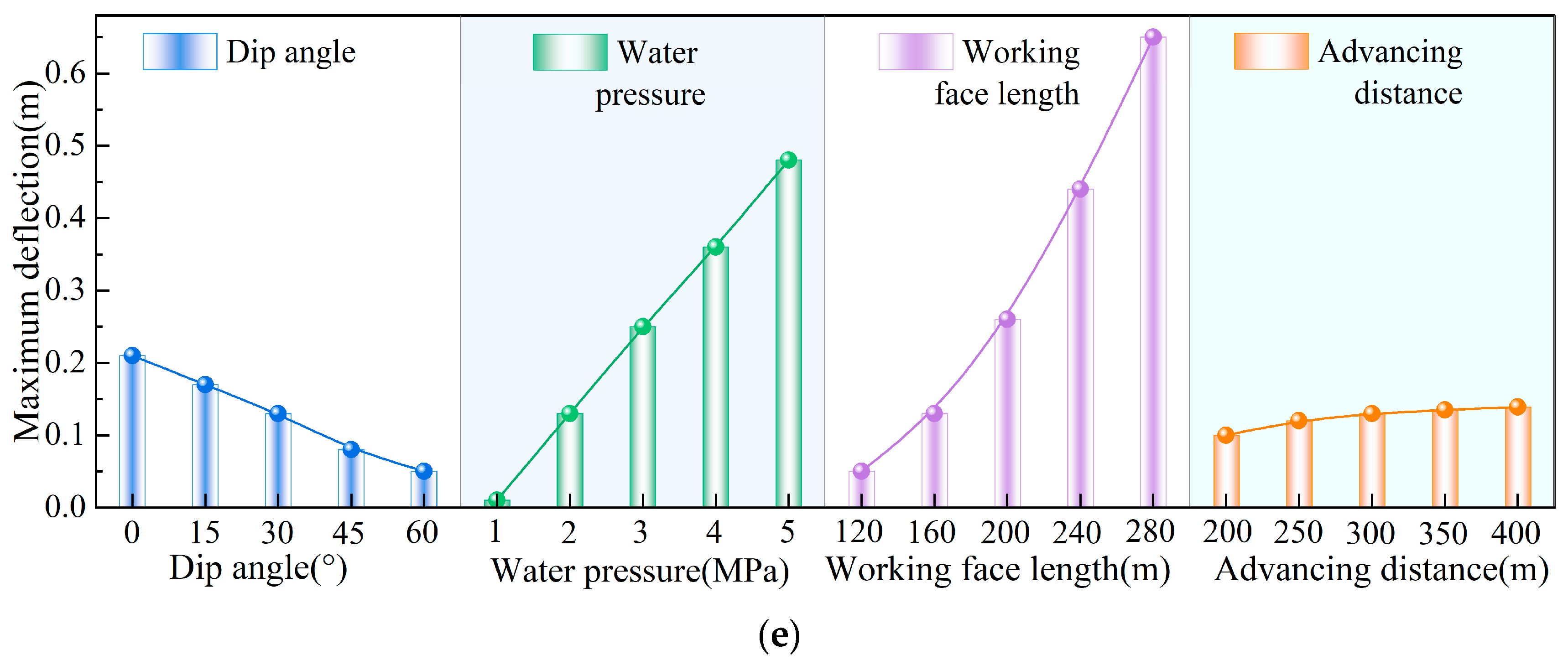
For computational simplicity, a symmetrically laminated plate is adopted, consisting of three mudstone layers interbedded with two sandstone layers. The mudstone has a Poisson’s ratio of 0.30, elastic modulus 2 GPa, and permeability 5 × 10–13 m2; the corresponding values for sandstone are 0.25, 10 GPa, and 3 × 10–12 m2. The distributions of floor aquiclude deflection under different factors are shown in Figure 2. The location of the maximum deflection shifts toward the upper end, with the ratio of its position to panel length equal to 0.42. Deflection decreases approximately linearly with increasing dip angle (Figure 2a). This behavior arises because water pressure is decomposed into a transverse load (normal to the laminated plate) and a longitudinal load (in-plane). The transverse component governs deflection more strongly than the longitudinal one; as dip angle increases, the transverse component decreases while the longitudinal component increases, with rates controlled by trigonometric functions. Different treatments of water pressure lead to different trends. Liang et al. treated water pressure as acting normal to the aquiclude, reporting an increasing deflection with dip because the overburden’s transverse load diminishes with dip [7]. Comparing the undetermined coefficients, a purely normal pressure treatment yields a coefficient containing only a sine term in angle; since sin α increases with α , deflection increases but at a decreasing rate. In contrast, our formulation includes two sine terms and one cosine term, whose combined effect determines the observed decreasing trend.
Deflection is positively and linearly correlated with water pressure; increasing pressure from 1 to 5 MPa produces a deflection change of 0.48 m, indicating a pronounced influence (Figure 2b). When the panel length increases, deflection grows exponentially: growth is slow for 120–160 m, but accelerates markedly beyond 200 m (Figure 2c). This suggests that, for mining above high-pressure confined aquifers, panel length should be kept as short as practicable to mitigate floor deformation and the risk of groundwater loss, consistent with field practice where panel lengths are often ~100 m [19]. The advance distance has a much weaker effect: increasing it from 200 to 400 m changes deflection by only 0.04 m, implying that advance distance is not a controlling factor for mining above confined aquifers (Figure 2d).
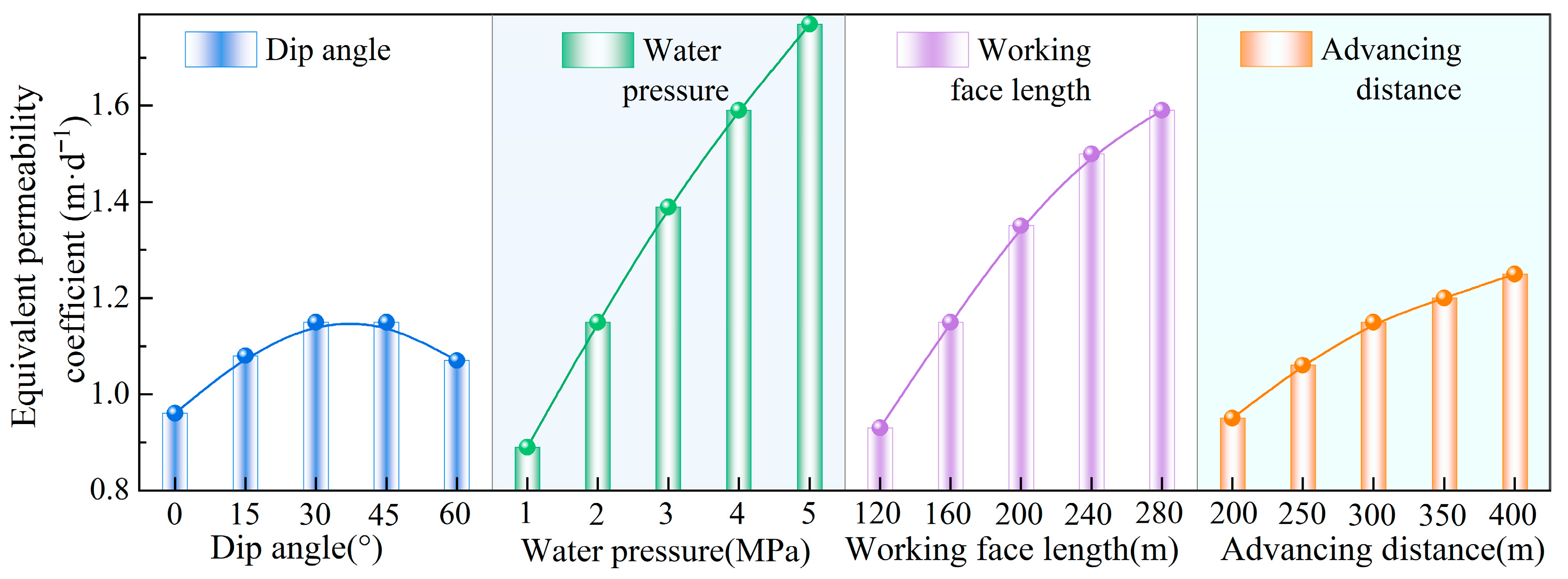
The overall equivalent hydraulic conductivity of the floor aquiclude under different influencing factors (converted from permeability) is shown in Figure 3. Its relationship with water pressure mirrors that of deflection versus pressure, exhibiting a linear increase with rising pressure. K eq also increases with panel length and advance distance, although the rate of increase diminishes as these parameters grow. The variation in equivalent permeability exhibits a new pattern compared to deflection changes, with a critical angle of 35°. Below this angle, equivalent permeability and dip angle show a positive correlation. This indicates a complex dip effect on the permeability of the floor, consistent with the variation in unloading intensity observed in protective seam mining of inclined seams [39].
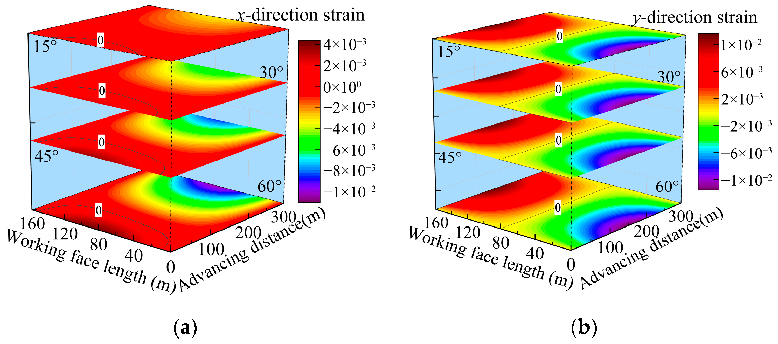
From Equations (10) and (11), the equivalent hydraulic conductivity is strongly correlated with the neutral plane strain and the aquiclude deflection. The x - and y -direction neutral plane strains for different dip angles are shown in Figure 4. Because the x direction is subjected to an in-plane load parallel to the laminated plate, the x -strain exhibits a markedly asymmetric distribution: the setup-entry side is dominated by tensile strain, whereas the stop line side is dominated by compressive strain, with the magnitude of compression exceeding that of tension due to the larger resultant longitudinal load at the end of mining. With dip angle increases, both tensile and compressive components increase in magnitude. Owing to the non-linear loading in both the x and y directions, the longitudinal load at the lower end exceeds that at the upper end, causing the zero-strain isopleth to shift toward the advance direction and the upper end. In contrast, the y -direction bearing characteristics yield a pronounced tensile compressive symmetry in the y -strain field. The peak y -strain increases with dip angle, although the growth rate diminishes at higher dips. The equivalent hydraulic conductivity K eq is inversely related to deflection and positively correlated with neutral plane strain. While larger dip angles correspond to smaller deflection, which would suggest an increasing K eq , the observed behavior is first increasing, then decreasing with dip. This indicates a shift in dominance between deflection and neutral plane strain. Under low dip angle conditions, deflection dominates K eq ; whereas under high dip angle conditions, neutral plane strain becomes the primary controlling factor.
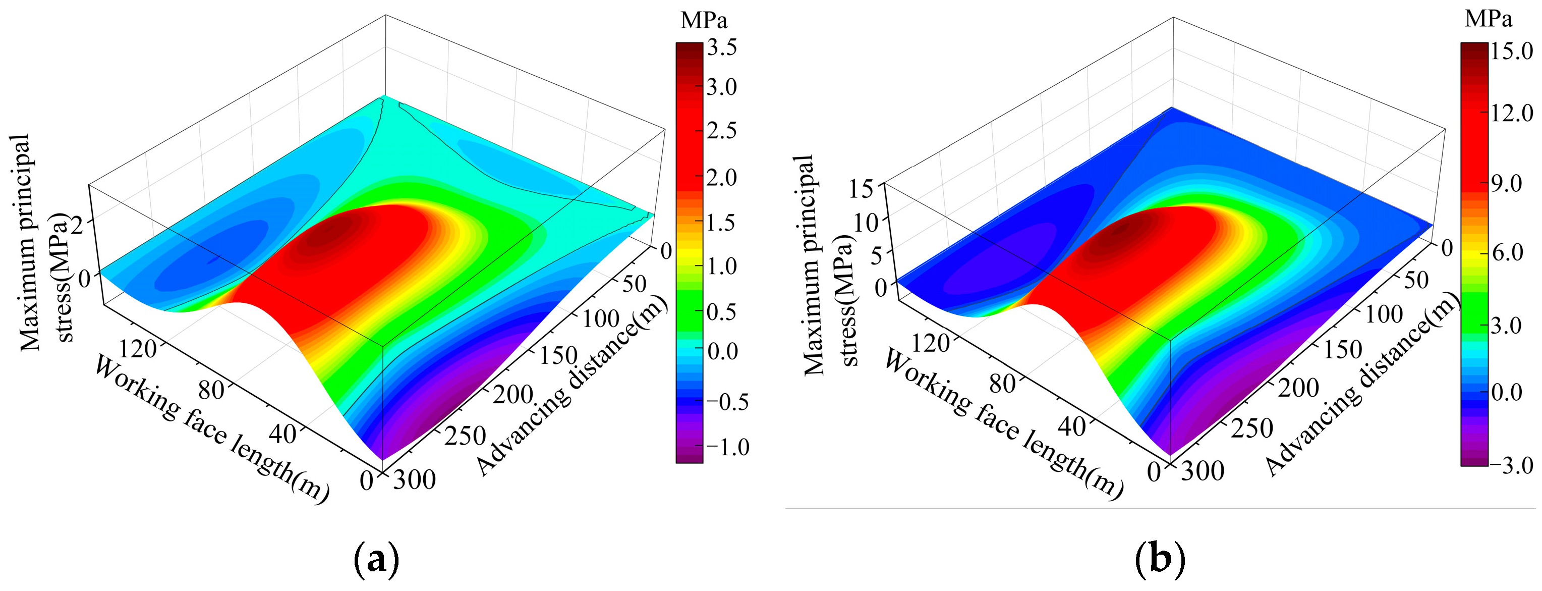
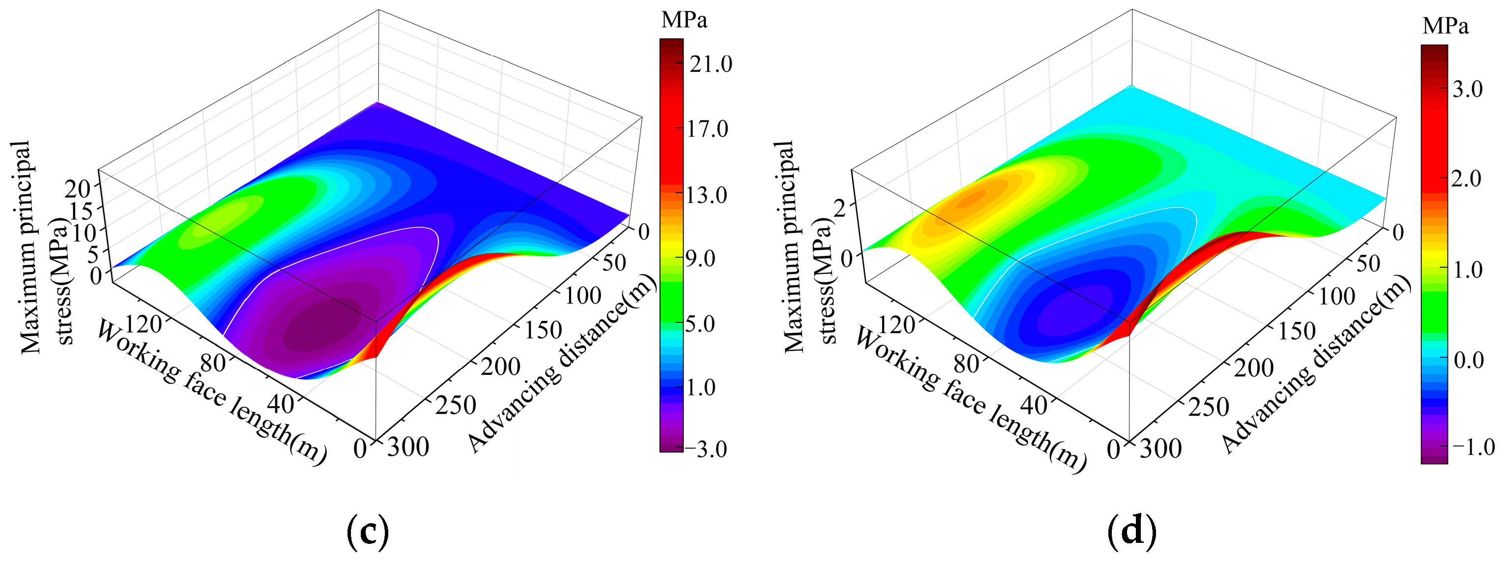
Using Combination ① as an example, Figure 5 illustrates the distributions of maximum principal stress on the top surfaces of Layers 1, 2, and the bottom surfaces of Layers 5, 6. Because the governing mechanical expressions are identical except for the coordinates, elastic modulus, and Poisson’s ratio, the stress patterns in the upper portion of the aquiclude are broadly similar. The distribution of principal stresses on the upper surface of the impermeable rock layer exhibits pronounced asymmetry. The central section of the working face on the first layer’s upper surface is a tensile zone, with the maximum stress point lagging 67 m behind the working face. Compressive zones are present on both sides of the working face, with greater compressive stress at the lower end than at the upper end. This indicates that tensile failure is more likely to occur in the upper part of the impermeable layer. In the lower portion, compression appears only in the mid-panel area; the upper end, lower end, and the rear of the goaf are all tensile. The tensile intensity ranks as lower end > upper end > coal wall > rear of goaf, reflecting potential instability at both ends of the face and delayed instability behind the goaf.

2.3. Effect of Lithologic Assemblage on Equivalent Hydraulic Conductivity

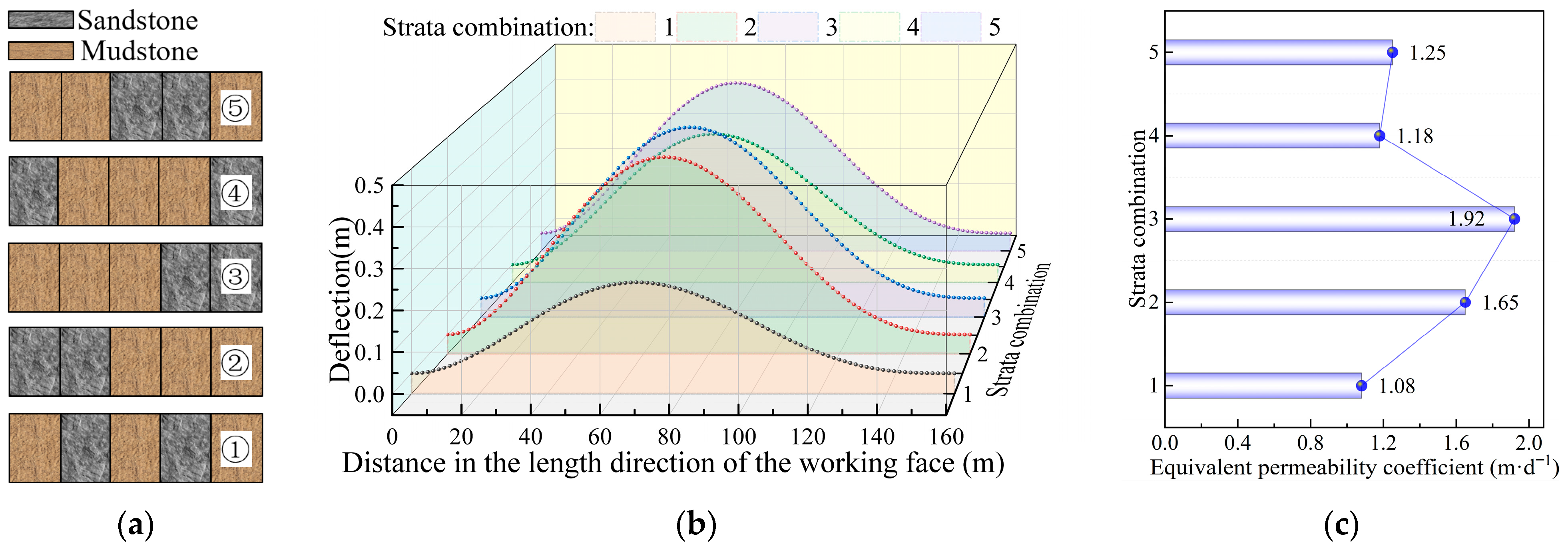
The essence of differing lithologic assemblages lies in the shift of the neutral plane position and the change in the bending stiffness matrix within the floor aquiclude. We consider five assemblages (Figure 6a): (i) interbedded soft–hard, (ii) hard over soft, (iii) soft over hard, (iv) hard–soft–hard (hard at top and bottom, soft in the middle), and (v) interbedded with soft–hard–soft (soft at top and bottom, hard in the middle). The neutral plane position is determined by a weighted average approach. Using a dip angle of 30° as an example (Figure 6b), the corresponding maximum deflections are 0.22, 0.45, 0.45, 0.35, and 0.42 m, respectively. These results indicate that interbedded floors effectively suppress deformation, with soft–hard interbeds performing best, followed by hard–soft–hard, then soft–hard–soft; by contrast, soft-over-hard and hard-over-soft produce larger deflections, consistent with prior findings [40], thereby supporting the reliability of the theoretical analysis.
Because the number of layers of each lithology is kept constant across assemblage schemes, the in-plane stiffness matrix and neutral plane strain remain essentially fixed; hence, the equivalent hydraulic conductivity is primarily controlled by deflection. Across the five assemblages, the equivalent conductivity spans 1.02–1.92 m/d (Figure 6c), demonstrating a substantial impact of lithologic configuration on the water-resistant performance of the floor. Notably, the variation in equivalent conductivity does not always mirror the change in deflection. For example, although the deflection magnitudes are equal for the soft-over-hard and hard-over-soft cases, the equivalent conductivity is greater for the former. This indicates that the contribution of deflection at different locations to permeability varies.

3. Multi-Parameter Model for Equivalent Permeability and Feasibility Assessment of In Situ Protection of Confined Floor Water

3.1. Engineering Background

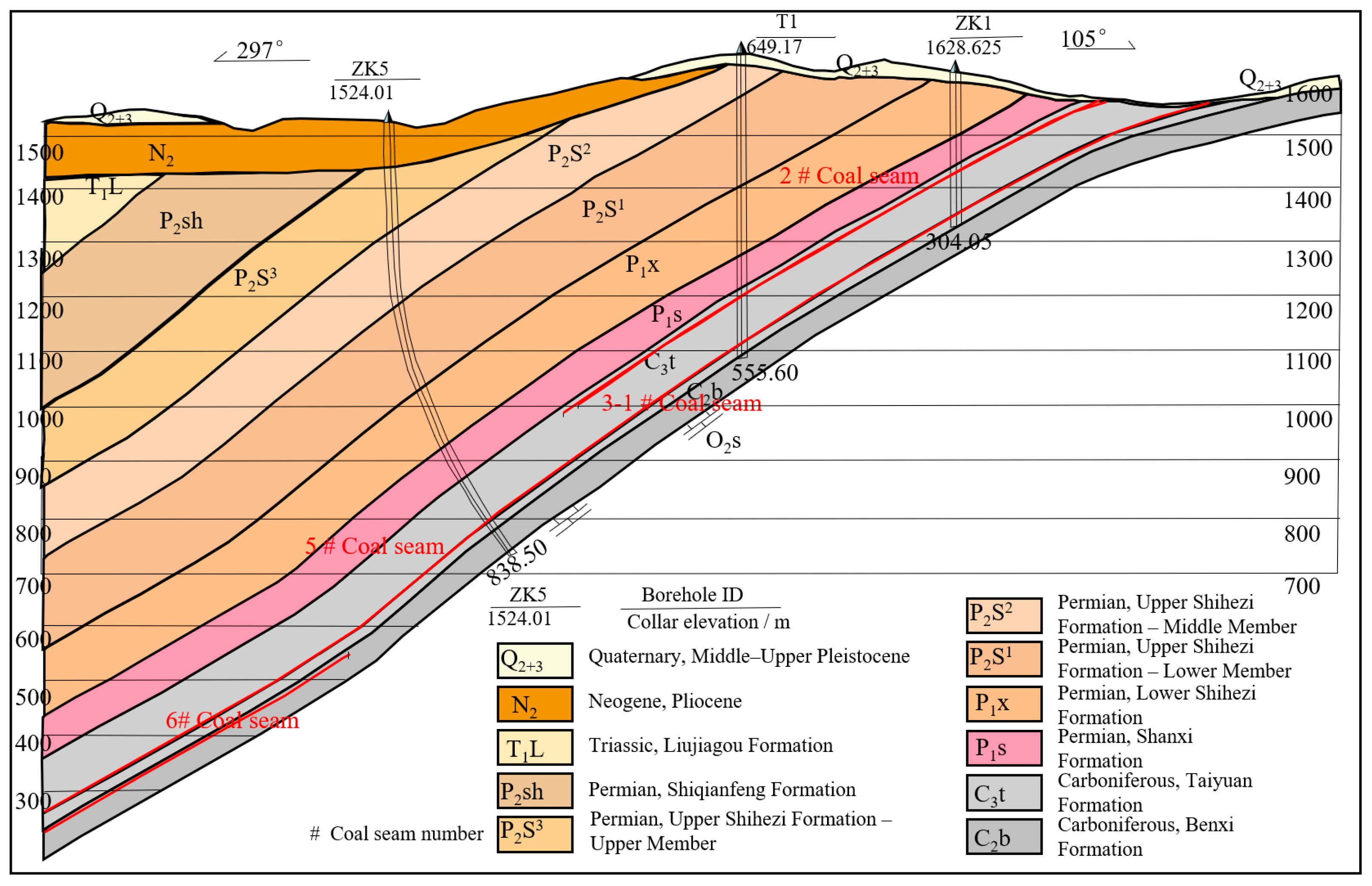
The Fenyuan Coal Mine is located south of Ducun Town, northeast of Jingle County, Shanxi Province. The lease area lies within the Yellow River Basin, in the Fen River system, and specifically within the recharge runoff zone of the Lower Jingyou Spring karst water system. The coal measure country rock aquifers are dominated by sandstone fracture water and karst fracture water. On Working Face 5-103, the coal seam is approximately 14.77 m thick with a dip of 20–40° and a panel length of 105 m. The average separation between the Ordovician limestone aquifer and the No. 5 coal seam is about 70 m, with water pressure ranging from 2.2 to 5.0 MPa. The borehole profile is shown in Figure 7.

3.2. Response Surface Methodology (RSM)-Based Model for Floor Permeability

Based on the borehole log profiles from the Fenyuan Coal Mine, the hydrogeological conditions are simplified. The specific parameters are listed in Table 2. The elastic matrices of different lithologies, as well as the in-plane and bending stiffness matrices of the laminated plate, are calculated as shown in Equation (16):
Q mudstone = 10 9 1.07 0.27 0 0.27 1.07 0 0 0 0.40 Q sandstone = 10 9 2.08 0.42 0 0.42 2.08 0 0 0 0.83 Q limestone = 10 9 95.61 20.77 0 20.77 95.61 0 0 0 37.40 A laminate = 10 10 9.56 2.08 0 2.08 9.56 0 0 0 3.74 D laminate = 10 11 10.42 2.47 0 2.47 10.42 0 0 0 3.99
The sensitivity analysis of factors influencing mining-induced floor permeability provides the basis for identifying the primary controls on permeability. Accurate predictions of permeability under different geological parameters (e.g., dip angle, water pressure) and mining parameters (e.g., working face length, mining height) are crucial for evaluating water-resistant performance in large-inclination-angle, high-pressure mining conditions. Although the equivalent permeability of the mining floor at the Fenyuan Coal Mine’s Working Face 5-103 can be directly determined through theoretical analysis, the Response Surface Method (RSM) approach allows for significance analysis and optimization design, which will provide important support for real-world engineering design and decision making. In this study, the Design-Expert 11 experimental design software is used, with the Box–Behnken module for response surface analysis. Four factors, each with three levels, are selected for the design, resulting in a total of 29 calculation schemes. The calculation schemes and corresponding results are shown in Table 3.
Based on the results from Table 3, the sensitivity of different influencing factors was verified. The overall F-value of the model is 14.8, indicating the model’s significance and confirming that the use of response surface analysis for the calculation data is feasible. The significance ranking of the factors based on their p-values is as follows: water pressure > working face length > advance distance > water pressure × water pressure > water pressure × working face length. To retain all significant terms, a quadratic function was used to fit the data, leading to the following multi-parameter response model for equivalent permeability:
K eq = 13.302 4.268 P 0.031 α 0.1296 a + 0.0036 b 0.0023 P α + 0.0165 P a   + 0.0028 P b + 0.006 α a + 0.0001 α b + 0.0001 a b + 0.059 P 2 0.0018 α 2 + 0.0002 a 2 0.0003 b 2
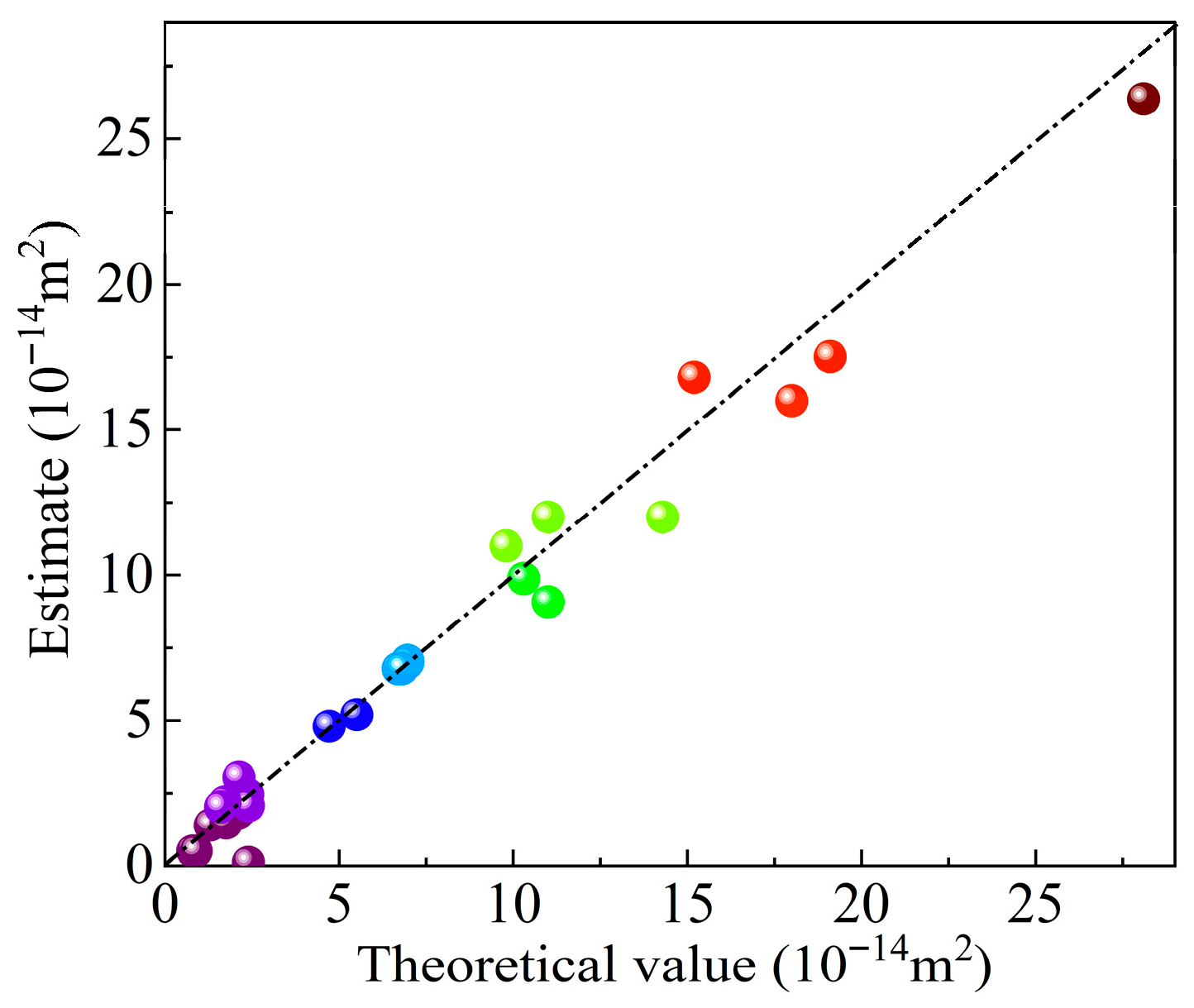
The model predictions and theoretical results are compared in Figure 8. As indicated by the axes, the closer the scatter points lie to the line y = x, the stronger the predictive performance. The points cluster closely on both sides of the line, with only slight deviations at higher values of equivalent permeability, indicating that the proposed model accurately captures the variation in K eq .

3.3. Multi-Factor Interaction Mechanism of Equivalent Permeability

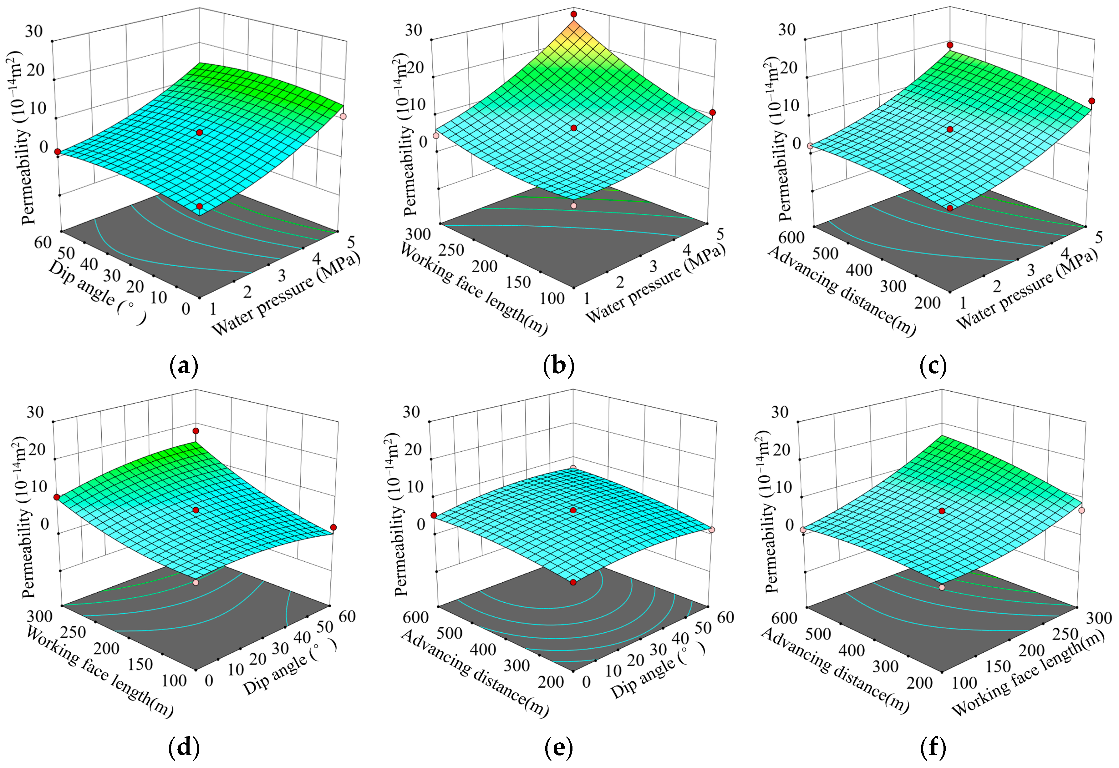
As shown in Figure 9, the evolution of equivalent permeability ( K eq ) under different factor combinations is visualized by response surfaces. The surface curvature effectively reflects the interaction between two factors, with interaction strength positively correlated with curvature. K eq increases with water pressure, and its correlation with dip angle strengthens accordingly (Figure 9a). With increasing dip, K eq first rises and then declines. The amplitude of this change is proportional to water pressure, i.e., the higher the pressure, the more pronounced the effect of dip angle on the floor’s K eq . This underscores the need to account for dip angle under high-pressure conditions.
The interaction between water pressure and panel length is significant (Figure 9b). The response surface is overall concave, indicating that larger panel length and higher water pressure jointly lead to a stronger increase in K eq . The response of K eq to water pressure and advance distance resembles that for dip angle and water pressure: the influence of advance distance becomes more significant as water pressure increases (Figure 9c). Increasing advance distance makes the surface progressively flatter. For a fixed panel length, K eq first increases and then decreases with dip angle, and the significance of dip is higher when the panel is longer (Figure 9d). Thus, when water pressure is high and panel length is large, the effect of dip angle on K eq cannot be ignored. The response of K eq to dip angle and advance distance shows a relatively flat surface, implying a weak interaction between these two factors (Figure 9e). K eq and its response intensity are positively correlated with both advance distance and panel length (Figure 9f).

3.4. Decision Procedure for In Situ Protection of Floor Water

Building on our prior work [41], the feasibility of in situ protection for a roof aquifer can be judged from the relationship between the mining-induced equivalent permeability ( K eq ) of the floor and a critical permeability threshold. However, for confined floor aquifers, the large aquifer thickness and substantial recharge render a flow conservation-based criterion overly restrictive and potentially unsafe for panel recovery.
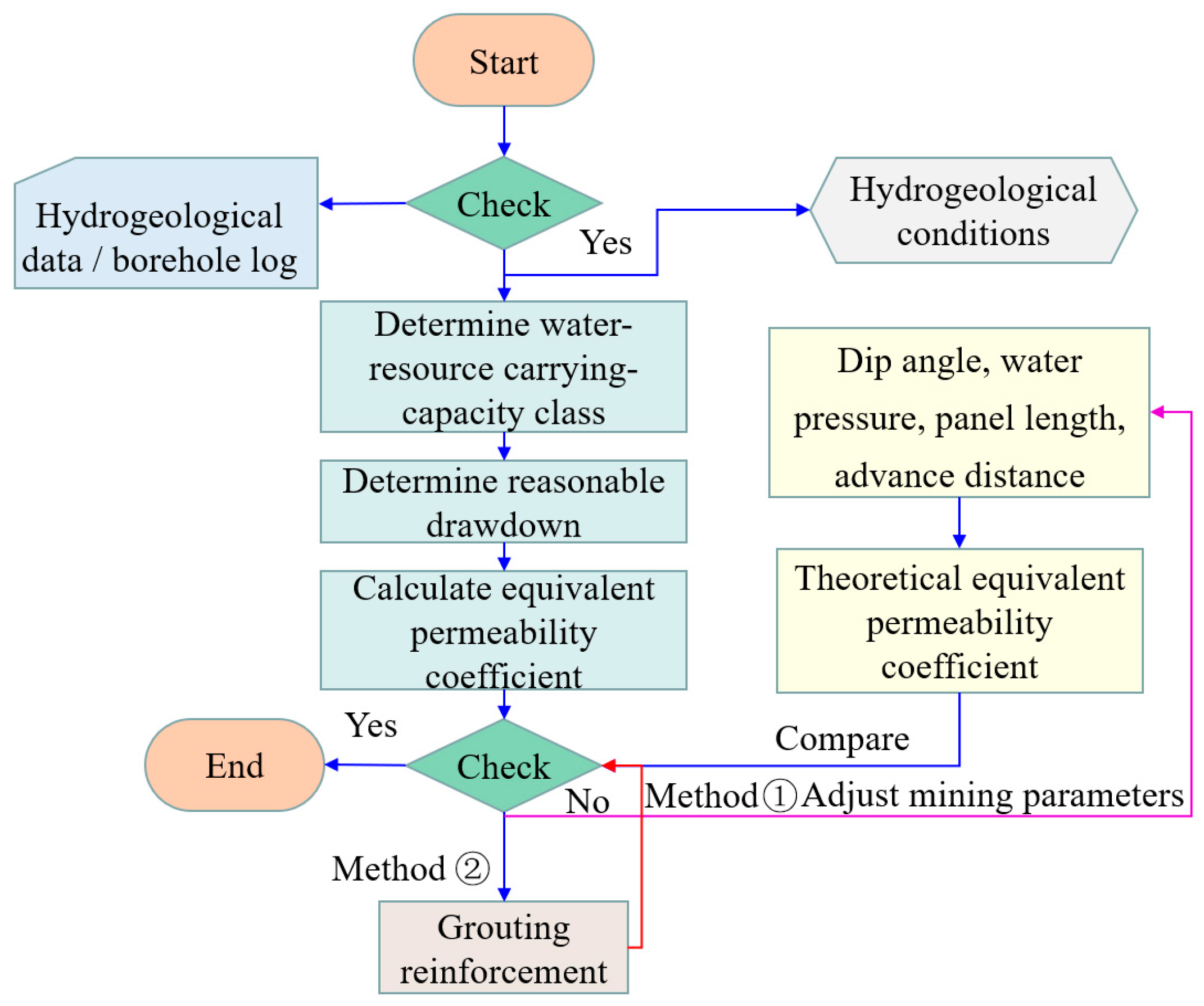
Here, we evaluate the mining impact on the groundwater system, i.e., the water-resource carrying capacity, using the drawdown-based hydrogeologic method (see calculations in [42]). The decision workflow for in situ protection of confined floor water is shown in Figure 10.
(1)
Scope and data collation. Target high-pressure confined aquifers. Compile hydrogeological data and borehole logs to judge both the protection value of the aquifer and the water-inrush risk during mining.
(2)
Carrying-capacity tiering. If the aquifer is worth protecting or the inrush risk is high, determine the mine’s allowable water-resource carrying-capacity class and the corresponding drawdown tier.
(3)
Permeability target. From the drawdown permeability relation, derive the required equivalent permeability K eq ; alternatively, adopt a critical equivalent permeability as the threshold.
(4)
Theoretical K eq . Using overburden conditions and hydrogeologic features, compute the theoretical equivalent permeability under its current dip angle, water pressure, panel length, and advance distance.
(5)
Gap analysis and control options. Compare the theory K eq with the required K eq . If theory K eq required K eq , apply one (or both) of the following: grouting reinforcement of the floor; design optimization (reduce panel length and/or adjust advance distance).
(6)
Iterate to compliance. Update parameters and recompute until both the equivalent permeability target and the carrying capacity requirement are satisfied; then proceed with normal panel extraction.
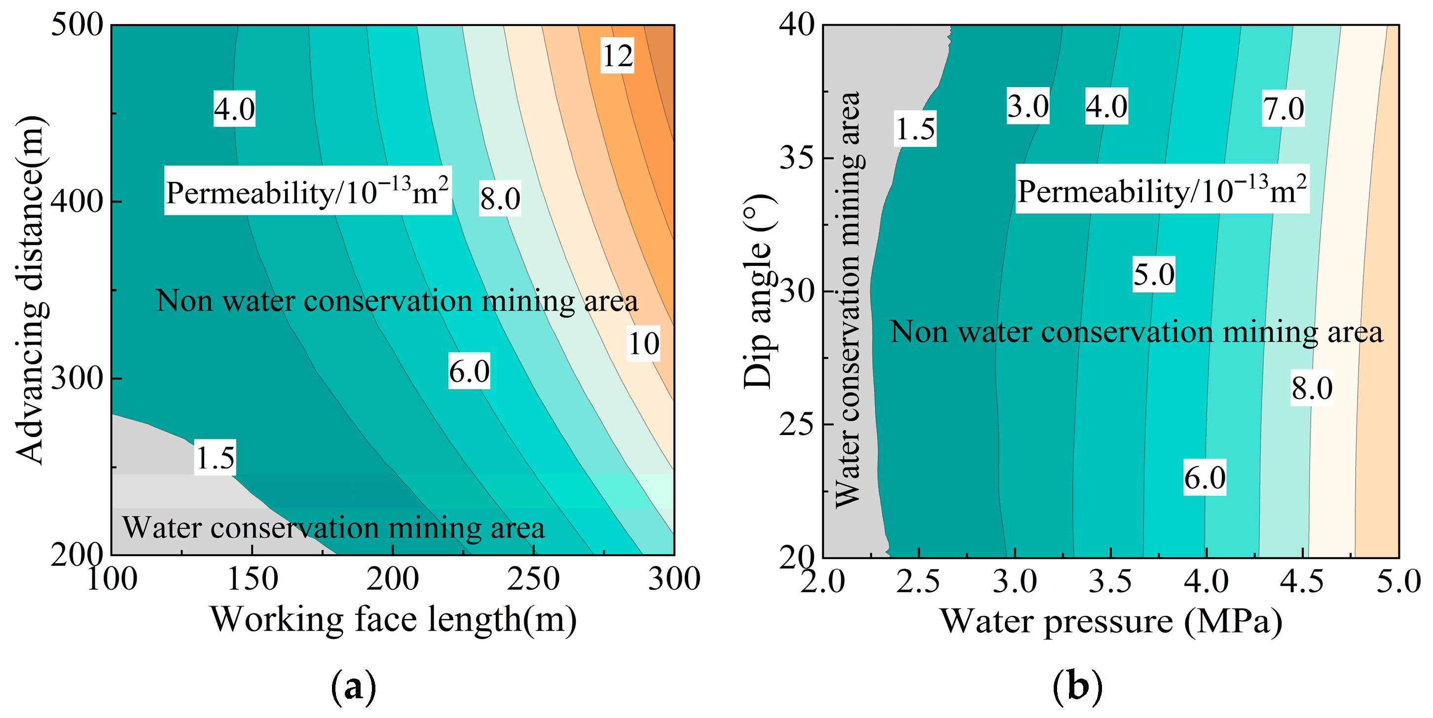
Based on the geological and hydrogeological conditions of Working Face 5-103 at the Fenyuan Coal Mine, and using the drawdown carrying-capacity relationship, the required equivalent permeability to achieve Grade III post-mining water resource carrying capacity is 1.5 × 10⁻¹³ m2. The theoretical and RSM multi-parameter models yield comparable estimates of the mining-induced floor equivalent permeability, both exceeding the requirement at 1.68 × 10⁻¹³, 1.82 × 10⁻¹³ m2, respectively; thus, under the current mining conditions, in situ protection of the floor water cannot be satisfied. The principal barrier layers are mudstone at horizons 5, 9, and 14, with permeabilities of 0.58 × 10⁻¹³, 0.67 × 10⁻¹³, and 0.54 × 10⁻¹³ m2, respectively.
To achieve in situ protection of floor water, Figure 11a shows the equivalent permeability under p = 2 MPa and α = 30°. A protection zone exists only when panel length and advance distance are both small, and these two parameters exhibit a negative correlation, a combination that would reduce mining efficiency. Using the current operating parameters for panel length and advance distance, the Keq-based partitioning of water conservation vs. non-conservation areas under different dip angles and water pressures (Figure 11b) indicates that water conservation mining is feasible only where p < 2.2 MPa, which clearly conflicts with the actual geological and hydrogeological conditions. Therefore, to reduce floor inflow on Working Face 5-103 while maintaining production efficiency, grouting modification of the aquiclude, via underground or regional treatment, is required.

4. Control of Mining-Induced Permeability and Water-Preservation Performance

4.1. Scheme for Controlling Mining-Induced Floor Equivalent Permeability

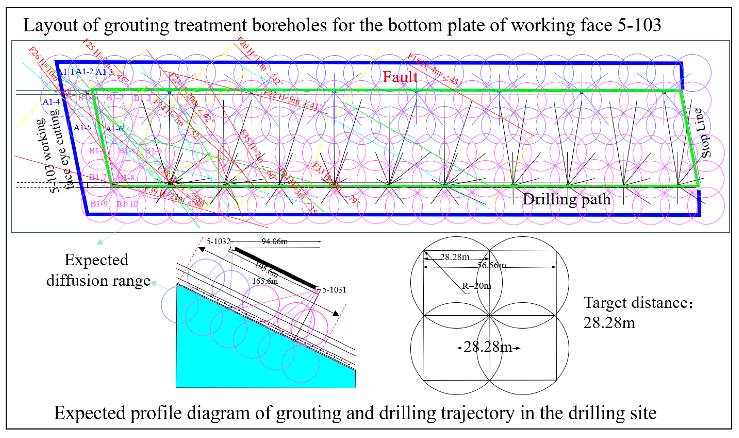
To further reduce groundwater loss during extraction on Working Face 5-103 of the Fenyuan Coal Mine, an underground borehole grouting program was implemented to modify the floor aquiclude and the upper 30 m of the Ordovician aquifer within the panel and a 30 m perimeter. In practice, 19 drilling stations were established, with 143 reinforcement/modification grout holes laid out at a 28.28 m spacing. Based on geophysical results, supplementary grout holes were added to structurally complex or previously missed zones for secondary reinforcement; these holes also served as grouting verification boreholes. The plan layout and borehole profile are shown in Figure 12. Geophysical prospecting was used to evaluate the reinforcement effect. Working Face 5-103 underwent two geophysical surveys; zones showing anomalies in the first survey received secondary grouting. Post-reinforcement verification boreholes recorded a maximum inflow < 5 m3/h, indicating that the grouting performance met the target criterion.

4.2. Working Face Inflow Variation Characteristics

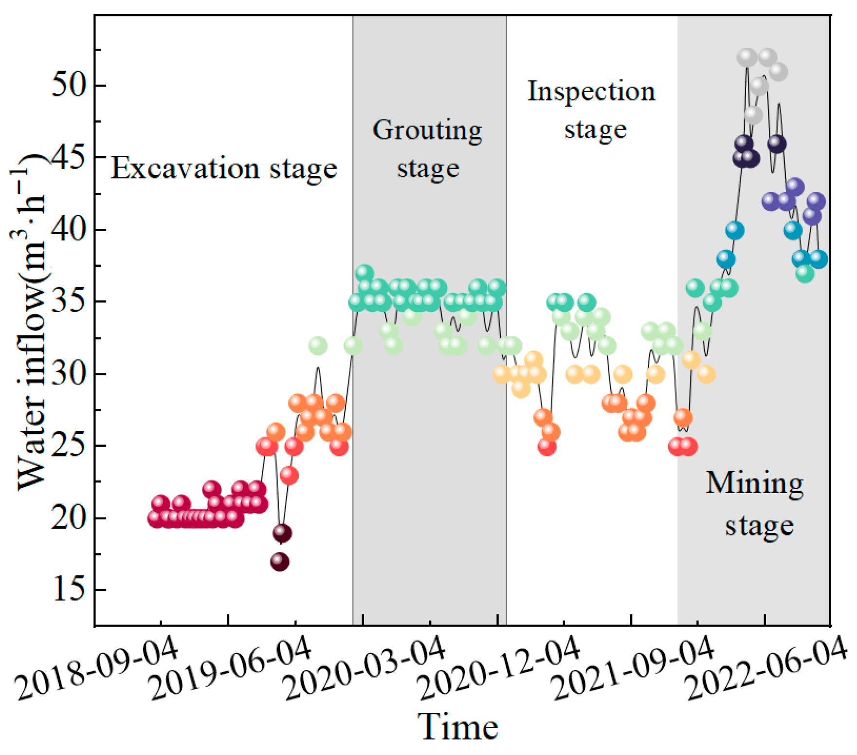
The evolution of inflow on Working Face 5-103 at different stages is shown in Figure 13. During roadway excavation, inflow varied little; it rose slightly toward the end of drivage to about 25 m3/h. Because aquifer drainage tests are fundamental for assessing water abundance and control measures, inflow increased to ~35 m3/h during the grouting-reinforcement period and then decreased markedly. During the secondary verification phase of floor grouting, inflow exhibited a rise–fall–rise pattern, with the second peak clearly lower than the first and stabilizing at the level observed at the end of drivage, further confirming the effectiveness of grouting reinforcement.
During panel extraction, inflow initially increased slowly, then rose rapidly, and finally declined, peaking at only 52 m3/h. At the start of mining, overburden movement and roof caving were insufficient, and the height/depth of mining-induced fractures was small. As the face advanced, fracture density and aperture within the affected zone increased, leading to higher inflow, which eventually decreased and stabilized at ~40 m3/h. These results indicate that, after grouting reinforcement, the working face achieved effective water conservation mining. Nevertheless, the source of inflow should be identified to confirm whether the target Ordovician aquifer was indeed protected in situ.

4.3. Water-Quality Characteristics and Inflow Sources

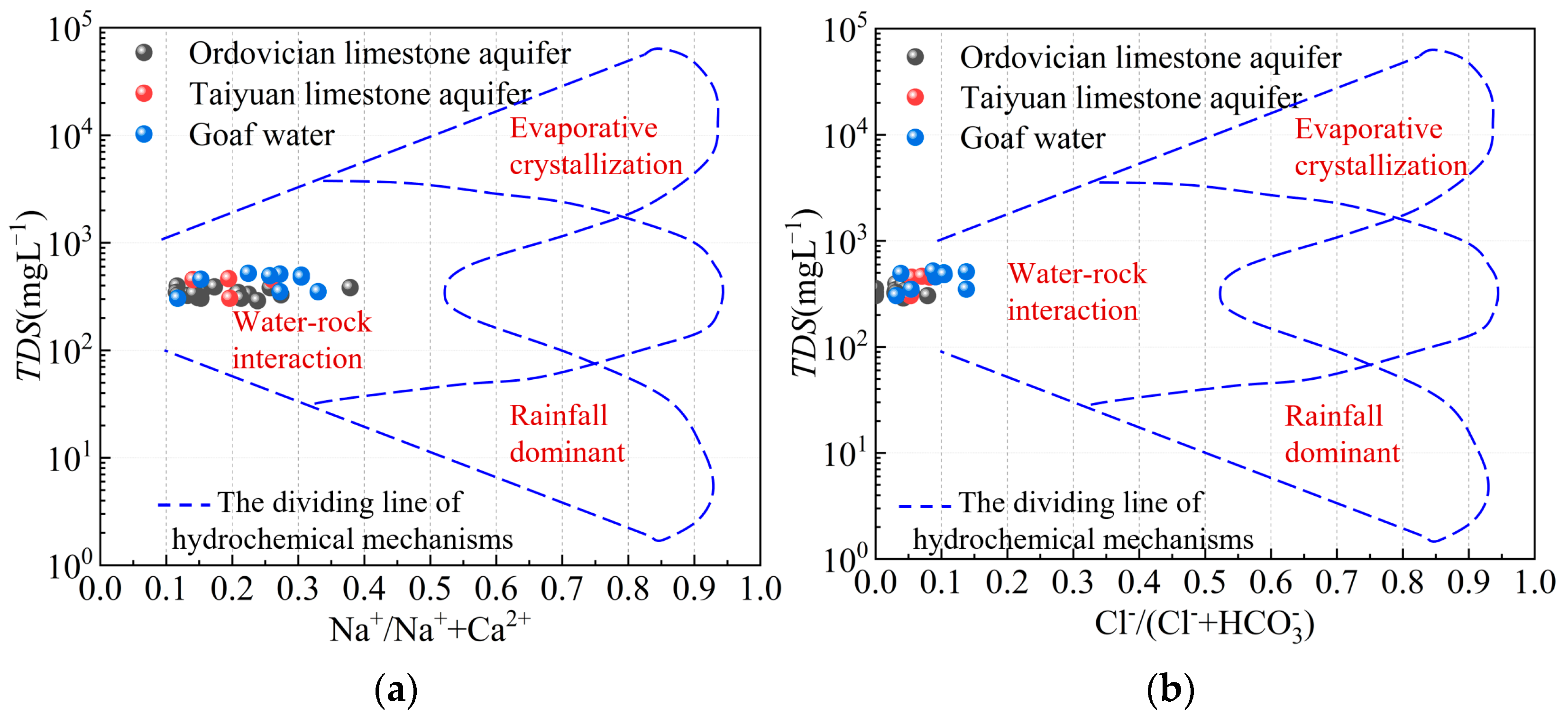
During panel extraction, goaf water, roof water, and floor water were sampled periodically. The Gibbs diagram was used to diagnose hydrochemical genesis, and the plots for different sample types are shown in Figure 14. The ratio Na+/(Na+ + Ca2+) ranges from 0.10 to 0.43; using 0.50 as a reference boundary, most groundwater exhibits Na+ lower than Ca2+. The ratio Cl/(Cl + HCO3) is <0.15 for all samples, indicating HCO3 ≫ Cl; no clear differences are observed among water types. The vast majority of samples plot in the rock–water interaction dominance field, implying that water–rock interaction is the primary control on hydrochemical ion evolution in the study area.
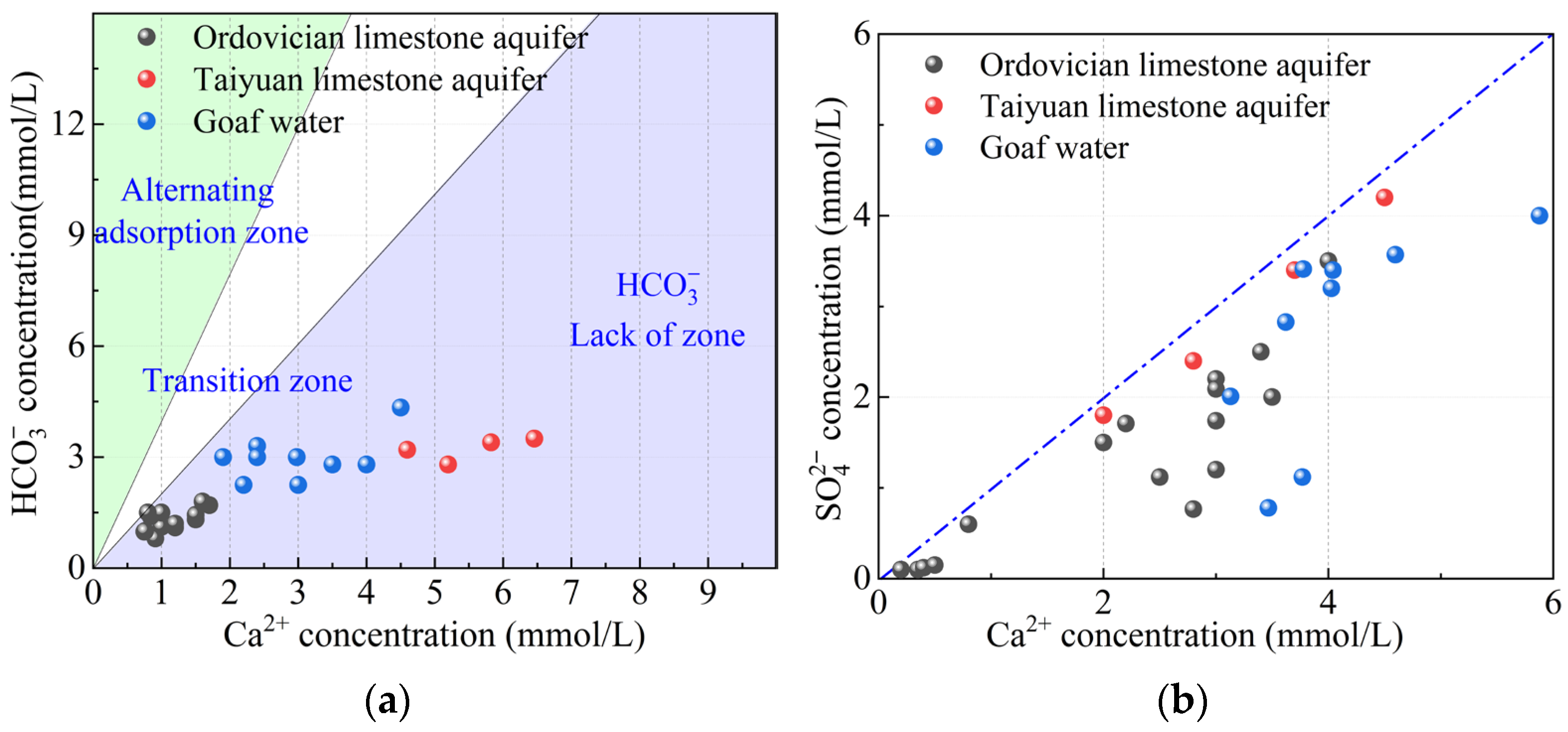
Proportions among ions can diagnose hydrochemical processes and origins. From the dissolution–precipitation expression (17), the following applies: if calcite dissolution is the sole source of ions, then the molar ratio HCO3:Ca2+ = 2:1; if dolomite dissolution is the sole source, then the molar ratio HCO3:Ca2+ = 4:1.
CaCO 3 ( Calcite ) + H 2 O + CO 2 Ca 2 + + 2 HCO 3 CaMg CO 3 2 ( Dolomite ) + 2 H 2 O + 2 CO 2 Ca 2 + + Mg 2 + + 4 HCO 3 CaMg CO 3 2 ( Dolomite ) + CaCO 3 ( Calcite ) + 3 H 2 O 2 Ca 2 + + Mg 2 + + 6 HCO 3
Based on the ratio of HCO3 to (Ca2+ + Mg2+), three fields can be delineated in Figure 15a: a cation-exchange zone, a transition zone, and an HCO3-deficient zone. All tested samples plot in the HCO3-deficient zone, indicating that the groundwater’s sulfate has additional sources. Gypsum dissolution is constrained by the Ca2+/SO42− stoichiometric ratio (Equation (18)); in both the Ordovician and Taiyuan limestone waters, the SO42− is not supplied solely by gypsum, consistent with the foregoing analysis. Mining-induced disturbance promotes fracture development in the aquiclude and oxidation of pyrite, yielding excess SO42− in roof limestone water and driving points toward the 1:1 line (Figure 15b). Thus, SO42− can be used as a diagnostic ion for source identification.
CaSO 4 2 H 2 O ( Gypsum ) Ca 2 + + SO 4 2 + 2 H 2 O   Gypsum   dissolution FeS 2 ( Pyrite ) + 15 4 O 2 + 7 2 H 2 O Fe ( OH ) 3 + 2 SO 4 2 + 4 H +   Oxidation   of   pyrite
The Piper diagrams for Ordovician limestone water (OLW) and Taiyuan limestone water (TLW) are shown in Figure 16. The floor OLW is predominantly of the HCO3-Ca·Mg type, whereas the roof TLW is of the SO4-Ca·Mg type. Based on the ionic distributions of OLW, TLW, and goaf water, cations show little differentiation among sample types; however, TLW and goaf water are sulfate-dominated (SO42−), while OLW is bicarbonate-dominated (HCO3). Accordingly, SO42− and HCO3 can be used as diagnostic ions for aquifer identification. The goaf water plots as SO4-Ca·Mg, trending closer to the roof water field, which indicates that the Ordovician confined aquifer in the floor was protected in situ.

5. Discussion

In recent years, research on water conservation mining has expanded its scope, shifting the focus from floor confined water hazard control to water resource protection. The decrease in or loss of overall water resistance performance of the bottom plate under mining disturbance is the essence of the water level decline, geological environment deterioration, and water resource loss in the high-pressure aquifer. A mechanical model was developed to characterize the coordinated deformation of floor aquiclude strata, accounting for non-uniform distributions of stress and water pressure, focusing on rock strata below the failure zone and above the aquifer. It is worth noting that the model does not account for the influence of horizontal stresses on the floor deformation. If necessary, horizontal stresses can be applied as internal forces, as simultaneously applying fixed boundaries and stress boundaries is ineffective [43]. Additionally, due to severe impact conditions in certain mining areas, the dynamic loading effects caused by roof collapses will induce localized over-pore pressure phenomena, thereby altering the pore pressure boundary conditions [44]. Meanwhile, the dip angle results in a relatively complex stress environment within the bedrock. In previous research, the author investigated rock strength under various loading angles and shear forces, finding that the loading angle can significantly reduce rock strength [45], a factor also not considered in the manuscript. The above shortcomings will be addressed in future research.
Based on the “three equivalences” theory proposed by our group [41], it can be applied to various geological conditions, such as faults and geologically anomalous bodies. This study develops an equivalent permeability model for the mining floor under steep dip and high water pressure, and proposes a feasibility assessment for in situ protection of floor confined water. With increasing dip angle, the floor equivalent permeability first increases and then decreases. The proposed new perspective indicates that the influence of dip angle on permeability exhibits a threshold effect; however, under high-pressure conditions, the impact of dip angle must be taken into account. The multi-parameter response model of equivalent permeability enables quantitative prediction of floor permeability under different geological parameters (e.g., dip, pressure) and mining parameters (e.g., advance distance, panel length), and provides a sensitivity ranking to guide the scientifically grounded design of operating parameters for in situ water conservation mining above high-pressure confined aquifers.
Grouting reinforcement of the floor is a key technology for enhancing water-blocking performance, yet the selection of grouting horizons and thicknesses is often experience-based. For the Ordovician confined aquifer, the weathered zone at the top, typically with good injectability, is commonly targeted [10]; to ensure effective barrier enhancement, outer modification of thin limestone layers may also be adopted [4]. The cooperative-deformation equivalent permeability model developed here enables refined screening of grouting parameters (target horizon, thickness, etc.). During preliminary design, sandstone with high injectability from the base rock failure zone down to the aquifer is typically selected for modification. By comparing the relationship between equivalent permeability (similar to the approach for different lithological combinations discussed earlier) and critical permeability across various modification levels and thicknesses, optimal reinforcement parameters can be determined, thereby providing a pre-mining diagnostic for in situ water conservation mining over large-inclination-angle, high-pressure aquifers.
That said, asymmetric deformation and stress fields prevail under steep-dip conditions, and the lower end faces a higher water-inrush risk than the upper end; thus, optimal grouting parameters should be non-uniform. To ensure operational safety in the present field application, we adopted a conservative, uniform drilling layout without spatially varying reinforcement parameters, an aspect to be addressed in future work.

6. Conclusions

Predicting mining-induced floor permeability is a key challenge for water conservation mining above high-pressure confined aquifers. To clarify the evolution of floor equivalent permeability under varying geological and operational conditions and to elucidate the mechanism by which dip angle affects floor permeability, this study develops a cooperative-deformation mechanical model for a floor aquiclude assemblage under non-uniform stress and water pressure, identifies the primary controls on mining-induced permeability, and proposes a decision criterion for in situ protection of floor water. These findings provide new insights for pre-mining planning of steeply inclined high-pressure coal seams, effectively safeguarding regional water ecological security and sustainable water resource utilization while preventing water inrush disasters and groundwater system disruption caused by mining activities, achieving a win–win situation for coal mining and water resource protection. The main conclusions are as follows:
(1)
The mining-induced floor equivalent permeability is inversely proportional to deflection and positively proportional to neutral plane strain. As the dip angle increases, the deflection of the floor aquiclude decreases approximately linearly, while the extreme value of neutral plane strain increases, revealing a shift in the dominant control on permeability between neutral plane strain and deflection with dip. The equivalent permeability first increases and then decreases with a turning point at 35°.
(2)
Lithologic assemblage affects the position of the neutral plane and the bending-stiffness matrix. A soft–hard interbedded floor effectively suppresses deformation and reduces equivalent permeability. Deflection at different locations contributes unevenly to equivalent permeability. For an inclined water-resistant key stratum, the hazard ranking of failure-prone zones for water inrush is as follows: lower end > upper end > coal wall position > rear of the goaf.
(3)
A quadratic multi-parameter coupling model of mining-induced floor equivalent permeability was constructed, identifying panel length and water pressure as the primary controls. The influence of dip angle on equivalent permeability becomes more pronounced when water pressure and panel length are larger.
(4)
Water–rock interaction is the main driver of hydrochemical ion evolution in the study area; dissolution/leaching dominates groundwater ion evolution. In the roof limestone aquifer, SO42− arises from gypsum dissolution and pyrite oxidation, and can serve, together with HCO3, as a diagnostic ion for distinguishing aquifers.
(5)
The feasibility of in situ protection of floor water for Working Face 5-103 at the Fenyuan Coal Mine was determined: under the current mining parameters, the requirement is met only when water pressure < 2.2 MPa. After on-site grouting reinforcement to increase resistance, the working-face inflow stabilized at 40 m3/h, composed mainly of roof limestone water, indicating that the targeted high-pressure Ordovician floor aquifer was protected in situ.

Author Contributions

Z.F.: methodology, software, writing—original draft, writing—review and editing. G.F.: conceptualization, methodology. D.Z.: conceptualization, formal analysis. T.L.: data curation. C.Y.: software, investigation. X.G.: validation, supervision. Z.K.: supervision, data curation. All authors have read and agreed to the published version of the manuscript.

Funding

This work was financially supported by the following: National Key Research and Development Program Project [grant number 2024YFC3909301, 2024YFC3909302]; National Natural Science Foundation of China [grant number 52404152]; Excellent Postdoctoral Funding Project of Jiangsu Province [grant number 2023ZB517]; Basic Research Funds for Central Universities—Youth Science and Technology Fund [grant number 2024QN11078].

Institutional Review Board Statement

Not applicable.

Informed Consent Statement

Not applicable.

Data Availability Statement

The data that support the findings of this study are available from the corresponding author upon reasonable request.

Acknowledgments

The authors are also grateful to the helpful comments provided by the anonymous reviewers.

Conflicts of Interest

The authors declare that they have no conflicts of interest.

Abbreviations

The following abbreviations are used in this manuscript:
a panel length (m) b advance distance (m)
α coal seam dip angle (°) A i j extensional stiffness matrices (N/m)
A xy undetermined coefficient B i j coupling stiffness matrices (N)
D i j bending stiffness matrices (N·m) D isotropic bending stiffness (N·m)
H m 1 the heights of the lower fractured zones (m) H m 2 the heights of upper fractured zones (m)
k current permeability (m2) k 0 initial permeability (m2)
ε v volumetric strain ϕ 0 initial porosity
k eq i equivalent permeability of strata I (m2) k eq mining-induced equivalent permeability (m2)
L deformation elements of length (m) L j deformation elements of length i (m)
k ( x , y ) current permeabilities at an arbitrary point in the floor (m2) k 0 ( x , y ) initial permeabilities at an arbitrary point in the floor (m2)
K x mid-plane curvature in the x direction (m−1) K y mid-plane curvature in the y direction (m−1)
K x y mid-plane curvature in the xy direction (m−1) ( Q ¯ i j ) k the transformed reduced stiffness (Pa)
M x moment in the x direction (N·m) M y moment in the y direction (N·m)
M x y moment in the xy direction (N·m) m m series orders
M total thickness of the strata (m) M i the thickness of a single layer
N x internal force per unit width in the x direction (N) N y internal force per unit width in the y direction (N)
N x y internal force per unit width in the xy direction (N) n n series orders
P 0 water pressure at the upper end (Pa) n total number of floors
p 1 stress perpendicular to the laminate (Pa) p 2 stress parallel to the laminate (Pa)
q 1 water pressure perpendicular to the laminate (Pa) q 2 water pressure stress parallel to the laminate (Pa)
γ w the unit weights of water (N/m3) γ the unit weights of rock (N/m3)
τ Poisson’s ratio total potential energy (J)
ε x 0 mid-surface strain in the x direction ε y 0 mid-surface strain in the y direction
γ x y 0 mid-surface strain in the xy direction U the deformation energy of the laminated plate
u 0 displacements in the x direction (m) u neutral plane displacements in the x direction (m)
v 0 displacements in the y direction (m) v neutral plane displacements in the y direction (m)
w 0 displacements in the z direction (m) w neutral plane displacements in the z direction (m)
W 1 work done by the transverse load (J) W 2 work done by the longitudinal load (J)
z k layer k of the laminates z k 1 layer k-1 of the laminates
Acronyms
RSMresponse surface method

References

  1. Huang, L.; Xu, Y.; Liu, S.; Gai, Q.; Miao, W.; Li, Y.; Zhao, L. Research on the Development Law of Pre-Mining Microseisms and Risk Assessment of Floor Water Inrush: A Case Study of the Wutongzhuang Coal Mine in China. Sustainability 2022, 14, 9774. [Google Scholar] [CrossRef]
  2. Wang, P.; Jiang, Y.; Ren, Q. Roof Hydraulic Fracturing for Preventing Floor Water Inrush under Multi Aquifers and Mining Disturbance: A Case Study. Energies 2022, 15, 1187. [Google Scholar] [CrossRef]
  3. Li, Y.; Yin, H.; Dong, F.; Cheng, W.; Zhuang, N.; Xie, D.; Di, W. The key to green water-preserved mining: Prediction and integration of mining rock failure height by big data fusion simulation algorithm. Process. Saf. Environ. Prot. 2025, 193, 1015–1035. [Google Scholar] [CrossRef]
  4. Zhang, J.; Guo, L.; Mu, W.; Liu, S.; Zhao, D. Water-inrush Risk through Fault Zones with Multiple Karst Aquifers Underlying the Coal Floor: A Case Study in the Liuzhuang Coal Mine, Southern China. Mine Water Environ. 2021, 40, 1037–1047. [Google Scholar] [CrossRef]
  5. Gao, Y.; Zhang, X.; Gai, Q.; Han, D.; He, M. An integrated method to prevent confined floor water inrush based on no pillar mining with pressure relief and grouting reinforcement. Geomech. Geophys. Geo-Energy Geo-Resour. 2025, 11, 85. [Google Scholar] [CrossRef]
  6. Li, Q.; Meng, X.; Liu, Y. Sensitivity analysis of water inrush evaluation model based on the theory of water resistant key strata: A case study in a coal mine, China. Earth Sci. Inform. 2022, 15, 2481–2494. [Google Scholar] [CrossRef]
  7. Liang, S.; Zhang, D.; Fan, G.; Kovalsky, E.; Fan, Z.; Zhang, L.; Han, X. Mechanical structure and seepage stability of confined floor response to longwall mining of inclined coal seam. J. Cent. South Univ. 2023, 30, 2948–2965. [Google Scholar] [CrossRef]
  8. Zhang, Y.; Cui, B.; Wang, Y.; Zhang, S.; Feng, G.; Zhang, Z. Evolution Law of Shallow Water in Multi-Face Mining Based on Partition Characteristics of Catastrophe Theory. Fractal Fract. 2023, 7, 779. [Google Scholar] [CrossRef]
  9. Dong, S.; Wang, H.; Guo, X.; Zhou, Z. Characteristics of Water Hazards in China’s Coal Mines: A Review. Mine Water Environ. 2021, 40, 325–333. [Google Scholar] [CrossRef]
  10. Cao, M.; Yin, S.; Lian, H.; Wang, X.; Wang, G.; Li, S.; Li, Q.; Xu, W. Failure Mechanism and Risk Evaluation of Water Inrush in Floor of Extra-Thick Coal Seam. Water 2025, 17, 743. [Google Scholar] [CrossRef]
  11. Liu, Z.; Dong, S.; Wang, H.; Wang, X.; Nan, S.; Liu, D. Macroscopic and mesoscopic development characteristics of the top strata of Middle Ordovician limestone in the Hanxing mining area. Environ. Earth Sci. 2021, 80, 526. [Google Scholar] [CrossRef]
  12. Li, J.; Xu, Y. Estimation of Aperture and Stiffness of Fractures under High Water Pressure Using Hydrological Data and Slurry Consolidating Body. Geofluids 2022, 2022, 1–10. [Google Scholar] [CrossRef]
  13. Zeng, Y.; Yang, D.; Wu, Q.; Cui, Y.; Liu, Z. Mechanism of Instantaneous High-Strength Sand—Water Inrush in Steeply Inclined Mining of Soft Coal Seam under Disturbed Rock—Soil Overburden. Lithosphere 2024, 2024, 3. [Google Scholar] [CrossRef]
  14. Ran, Q.; Liang, Y.; Ye, C.; Ning, Y.; Ma, T.; Kong, F. Failure analysis of overlying strata during inclined coal seam mining: Insights from acoustic emission monitoring. Eng. Fail. Anal. 2025, 182, 110023. [Google Scholar] [CrossRef]
  15. Eremin, M.; Peryshkin, A.; Esterhuizen, G.; Pavlova, L.; Fryanov, V. Numerical Analysis of Pillar Stability in Longwall Mining of Two Adjacent Panels of an Inclined Coal Seam. Appl. Sci. 2022, 12, 11028. [Google Scholar] [CrossRef]
  16. Zhou, R.; Wang, H.; Shu, C.; Chu, T. Study on the pressure relief effect in gob-side coal body during mining an inclined longwall panel. Energy Sci. Eng. 2021, 9, 1530–1542. [Google Scholar] [CrossRef]
  17. He, J.; Li, W.; Qiao, W. P-H-q evaluation system for risk assessment of water inrush in underground mining in North China coal field, based on rock-breaking theory and water-pressure transmission theory. Geomat. Nat. Hazards Risk 2018, 9, 524–543. [Google Scholar] [CrossRef]
  18. Wei, M.; Zhu, Y.; Wang, P.; Luo, Y.; Ren, H.; Li, P. Failure characteristics and stress field distribution law of roadway in downward mining of deep close distance coal seam. Sci. Rep. 2024, 14, 28735. [Google Scholar] [CrossRef]
  19. Liang, Z.; Song, W.; Liu, W. Theoretical models for simulating the failure range and stability of inclined floor strata induced by mining and water pressure. Int. J. Rock Mech. Min. Sci. 2020, 132, 104382. [Google Scholar] [CrossRef]
  20. Liang, Z.; Song, W. Theoretical and Numerical Investigations of the Failure Characteristics of a Faulted Coal Mine Floor Above a Confined Aquifer. Mine Water Environ. 2021, 40, 456–465. [Google Scholar] [CrossRef]
  21. Shang, Y.; Wang, Y.; Zhang, L.; Wu, G.; Kong, D.; Zhang, P.; Jia, T. Impact of Lower Protective Coal Seam Mining on Overlying Strata: Deformation, Pressure Relief, and Permeability Enhancement. Int. J. Geomech. 2024, 24, 9. [Google Scholar] [CrossRef]
  22. Zhang, D.; Fan, G.; Liu, Y.; Ma, L. Field trials of aquifer protection in longwall mining of shallow coal seams in China. Int. J. Rock Mech. Min. Sci. 2010, 47, 908–914. [Google Scholar] [CrossRef]
  23. Gong, X.; Xue, S.; Han, B.; Zheng, C.; Zhu, L.; Dong, Y.; Li, Y. Research Progress on Stress–Fracture–Seepage Characteristics for Hazard Prevention in Mine Goafs: A Review. Sustainability 2022, 14, 12107. [Google Scholar] [CrossRef]
  24. Zhang, C.; Tu, S.; Zhang, L. Field Measurements of Compaction Seepage Characteristics in Longwall Mining Goaf. Nat. Resour. Res. 2020, 29, 905–917. [Google Scholar] [CrossRef]
  25. Lu, S.; Li, M.; Ma, Y.; Wang, S.; Zhao, W. Permeability changes in mining-damaged coal: A review of mathematical models. J. Nat. Gas Sci. Eng. 2022, 106, 104739. [Google Scholar] [CrossRef]
  26. Zhou, H.W.; Zhao, J.W.; Su, T.; Zhang, L.; Zhong, J.C.; Liu, Z.L. Characterization of gas flow in backfill mining-induced coal seam using a fractional derivative-based permeability model. Int. J. Rock Mech. Min. Sci. 2021, 138, 104571. [Google Scholar] [CrossRef]
  27. Wu, Q.; Wang, M. Characterization of water bursting and discharge into underground mines with multilayered groundwater flow systems in the North China coal basin. Hydrogeol. J. 2006, 14, 882–893. [Google Scholar] [CrossRef]
  28. Xu, Y.; Luo, Y.; Li, J.; Li, K.; Cao, X. Water and Sand Inrush During Mining Under Thick Unconsolidated Layers and Thin Bedrock in the Zhaogu No. 1 Coal Mine, China. Mine Water Environ. 2018, 37, 336–345. [Google Scholar] [CrossRef]
  29. Zhao, J.; Zhang, X.; Jiang, N.; Yin, L.; Guo, W. Porosity zoning characteristics of fault floor under fluid-solid coupling. Bull. Eng. Geol. Environ. 2020, 79, 2529–2541. [Google Scholar] [CrossRef]
  30. Wu, Y.; Tang, Y.; Xie, P.; Hu, B.; Lang, D.; Wang, H. Stability analysis of ‘roof-coal pillar’ structure in longwall multi-section mining of steeply dipping coal seam. Geomat. Nat. Hazards Risk 2024, 15, 2359998. [Google Scholar] [CrossRef]
  31. Liu, H.; Li, X.; Liu, X.; Sun, Y.; Yang, Z.; Zhong, Y. Rule Study on the Risk of Floor Water Inrush Based on the Plate Model Theory. Sustainability 2023, 15, 7844. [Google Scholar] [CrossRef]
  32. Li, Y.; Tai, Y.; Yu, B.; Kuang, T.; Gao, R.; Liu, J. Evolution and control technology of energy aggregation and dissipation of a high hard roof during breakage and destabilization. Int. J. Fract. 2024, 245, 1–23. [Google Scholar] [CrossRef]
  33. Sun, J.; Wang, L.; Zhao, G. Stress Distribution and Failure Characteristics for Workface Floor of a Tilted Coal Seam. KSCE J. Civ. Eng. 2019, 23, 3793–3806. [Google Scholar] [CrossRef]
  34. Zhao, D.; Wu, Q.; Cui, F.; Xu, H.; Zeng, Y.; Cao, Y.; Du, Y. Using random forest for the risk assessment of coal-floor water inrush in Panjiayao Coal Mine, northern China. Hydrogeol. J. 2018, 26, 2327–2340. [Google Scholar] [CrossRef]
  35. Zhao, M.; Zhao, Y.; Wang, A.; Chang, Z.; Zhang, J.; Wang, Z. Investigation of the mode-I delamination behavior of Double-Double laminate carbon fiber reinforced composite. Compos. Sci. Technol. 2024, 248, 110463. [Google Scholar] [CrossRef]
  36. Yang, S.; Song, G.; Yang, J. An analytical solution for the geometric broken characteristics of the overlying strata and its physical modeling study in longwall coal mining. Arab. J. Geosci. 2020, 13, 139. [Google Scholar] [CrossRef]
  37. Fan, Z.; Fan, G.; Zhang, D.; Zhang, L.; Zhang, S.; Liang, S.; Yu, W. Optimal injection timing and gas mixture proportion for enhancing coalbed methane recovery. Energy 2021, 222, 119880. [Google Scholar] [CrossRef]
  38. Fan, Z.; Fan, G.; Zhang, D. Permeability and Energy Evolution Characteristics of Heterogeneous Coal and Rock Mass. Nat. Resour. Res. 2021, 30, 4493–4514. [Google Scholar] [CrossRef]
  39. Peng, X.; Qi, L.; Wang, Z.; Zhou, X.; Hua, C. Study on Overburden Movement Deformation and Roof Breakage Law of Under-Protective Steeply Inclined Coal Seam Mining. Sustainability 2022, 14, 10068. [Google Scholar] [CrossRef]
  40. Cong, R.; Yang, R.; Gong, Y.; Li, G.; Huang, Z.; Zhang, B. Numerical investigation of mechanical responses and failure features of coal measure strata using combined finite-discrete element method. Comput. Geotech. 2024, 171, 106346. [Google Scholar] [CrossRef]
  41. Zhang, D.; Fan, G.; Zhang, S.; Ma, L.; Wang, X. Equivalent water-resisting overburden thickness forwater-conservation mining: Conception, method and application. J. China Coal Soc. 2022, 47, 128–136. [Google Scholar]
  42. Chi, M.; Zhang, D.; Zhao, Q.; Yu, W.; Liang, S. Determining the scale of coal mining in an ecologically fragile mining area under the constraint of water resources carrying capacity. J. Environ. Manag. 2021, 279, 111621. [Google Scholar] [CrossRef] [PubMed]
  43. Liang, S.; Zhang, X.; Ke, F.; Liu, J.; Yao, Q.; Luo, H.; Li, X.; Xu, Y. Evolution of Overlying Strata Bed Separation and Water Inrush Hazard Assessment in Fully Mechanized Longwall Top-Coal Caving of an Ultra-Thick Coal Seam. Water 2025, 17, 850. [Google Scholar] [CrossRef]
  44. Zhou, K.; Dou, L.; Kan, J.; Yang, K.; Li, J.; Ma, X. Coal burst mechanism in large-scale panel under extra-thick key strata. Geomat. Nat. Hazards Risk 2024, 15, 2347420. [Google Scholar] [CrossRef]
  45. Fan, G.; Fan, Z.; Zhang, D.; Zhang, S. Rock strength and permeability under compression shear coupling corresponding to different loading angles. J. China Coal Soc. 2024, 49, 3090–3101. (In Chinese) [Google Scholar]
Figure 1. Mechanical model of collaborative deformation of aquitard. (a) Inclined coal seam mining; (b) dip direction; (c) strike direction.
Sustainability 17 10273 g001
Figure 2. Deflection distribution under different factors: (a) dip angle; (b) water pressure; (c) working face length; (d) advancing distance; (e) maximum deflection.
Sustainability 17 10273 g002aSustainability 17 10273 g002b
Figure 3. The correlation characteristics between the equivalent permeability coefficient and different factors.
Sustainability 17 10273 g003
Figure 4. Strains in x and y directions with inclination angle: (a) x-direction strain; (b) y-direction strain.
Sustainability 17 10273 g004
Figure 5. Characteristics of maximum principal stress distribution. (a) First layer upper surface; (b) second layer upper surface; (c) upper surface of the fifth layer; (d) upper surface of the sixth layer.
Sustainability 17 10273 g005aSustainability 17 10273 g005b
Figure 6. Evolution of equivalent permeability under different lithology assemblages. (a) Lithologic assemblage; (b) deflection; (c) equivalent hydraulic conductivity.
Sustainability 17 10273 g006
Figure 7. Hydrogeological profile.
Sustainability 17 10273 g007
Figure 8. Comparison of prediction with numerical test.
Sustainability 17 10273 g008
Figure 9. Response of equivalent permeability to multiple influencing factors: (a) dip angle–water pressure; (b) working face length–water pressure; (c) advancing distance–water pressure; (d) working face length–dip angle; (e) advancing distance–dip angle; (f) advancing distance–working face length.
Sustainability 17 10273 g009
Figure 10. Determination steps for water protection.
Sustainability 17 10273 g010
Figure 11. Characteristics of in situ protection zoning for bottom water: (a) with water pressure and dip angle fixed; (b) with working face length and advancing distance fixed.
Sustainability 17 10273 g011
Figure 12. Layout of grouting boreholes.
Sustainability 17 10273 g012
Figure 13. Water inflow of working face.
Sustainability 17 10273 g013
Figure 14. Gibbs diagram of different samples: (a) Na+/(Na+ + Ca2+); (b) Cl/(Cl + HCO3).
Sustainability 17 10273 g014
Figure 15. Water ion relationship of different samples: (a) Ca2+-HCO3; (b) Ca2+-SO42−.
Sustainability 17 10273 g015
Figure 16. Piper diagrams of different samples.
Sustainability 17 10273 g016
Table 1. Research subjects, theories, and assumptions.
Research
Subjects
TheoriesAssumptionDisplacement
Boundary Condition
Stress Boundary
Condition
References
Horizontal coal seamElastic thin plate theoryIsotropicFour-sided fixedUniform distribution of stress and
water pressure
[2]
Inclined coal seamElastic thin plate theoryIsotropicFour-sided fixedTop stress uniform distribution; non-uniform water pressure distribution at the bottom[6]
Inclined coal seamLaminate
theory
IsotropicFour-sided fixedMoving toward uniformity and tending toward non-uniformity; water pressure is perpendicular to the floor[7]
Horizontal coal seamBeam theoryIsotropicFour-sided fixedUniform distribution of stress and
water pressure
[17]
Horizontal coal seamElastic semi-infinite
theory
Isotropic/Top stress uniform distribution[18]
Inclined coal seamElastic half-space theoryIsotropic/Top stress uniform distribution; non-uniform water pressure distribution at the bottom[19]
Horizontal coal seamLimit equilibrium theoryIsotropic/Top stress uniform distribution[20]
Inclined coal seam
(proposed)
Laminate
theory
Isotropic within the layerFour-sided fixedUniform distribution of stress and
water pressure
/
Table 2. Borehole columnar generalization.
Thickness/mLithologyElastic
Modulus/GPa
Poisson’s RatioPorosity/%Permeability
/10−14 m2
3Mudstone10.251.52
5Sandstone20.202.510
11Mudstone10.251.52
3Sandstone20.202.510
2Mudstone10.251.52
3Limestone40.203.530
5Sandstone20.202.510
3Mudstone10.251.52
5Sandstone20.202.510
3Mudstone10.251.52
2Sandstone20.202.510
9Mudstone10.251.52
Table 3. Response surface design and corresponding results.
Standard OrderWater
Pressure/MPa
Dip Angle
Working Face Length/mAdvancing Distance/mPermeability
/10−14 m2
53301002001.05
273302004006.70
191303004004.72
23302006005.51
2053030040041.10
143601004001.05
243602006006.97
153030040010.30
833030060015.20
1253020060019.10
1636030040018.00
105302002004.29
111302006002.38
13301004001.13
171301004000.60
1102004000.86
31602004001.76
25020040011.00
283302004006.80
91302002000.80
21302002001.87
73301006001.53
223602002001.60
45602004009.80
293302004006.80
63303002001.98
253302004006.80
185301004002.40
263302004006.80
Disclaimer/Publisher’s Note: The statements, opinions and data contained in all publications are solely those of the individual author(s) and contributor(s) and not of MDPI and/or the editor(s). MDPI and/or the editor(s) disclaim responsibility for any injury to people or property resulting from any ideas, methods, instructions or products referred to in the content.