Review

Ventilation Technology of Diesel Locomotive Railway Tunnels: Current Trends, Sustainable Solutions and Future Prospects

1
School of Environmental and Municipal Engineering, Lanzhou Jiaotong University, Lanzhou 730070, China
2
State Key Laboratory of Intelligent Geotechnics and Tunnelling, Xi’an 710043, China
3
Guangzhou Municipal Housing Development and Transportation Bureau in Baiyun District, Guangzhou 510405, China
*
Authors to whom correspondence should be addressed.
Sustainability 2025, 17(21), 9766; https://doi.org/10.3390/su17219766
Submission received: 24 August 2025 / Revised: 24 October 2025 / Accepted: 29 October 2025 / Published: 2 November 2025
(This article belongs to the Special Issue Tunneling and Underground Engineering: A Sustainability Perspective)

Abstract

Ventilation systems in railway tunnels are crucial for ensuring the safe operation of trains, particularly those powered by diesel locomotives. Inadequate ventilation design may cause serious traffic accidents. Previous studies were generally focused on tunnel ventilation issues for highway tunnels or high-speed railway tunnels, while little attention has been paid to systematic ventilation design for diesel locomotive railway tunnels. To summarize the research progress and find a sustainable solution of ventilation for diesel locomotive railway tunnels, a comprehensive review of the relevant literature was conducted in this paper. First, the development history of diesel locomotives is traced, and the main framework and key components of a diesel locomotive railway ventilation system are introduced. Then, the limit values of locomotive emissions within tunnels specified in different standards from different countries are compared. Finally, key factors affecting the performance of ventilation systems in diesel locomotive railway tunnels are sorted. It is found that diesel locomotives remain the primary choice for railway freight traction in developing countries and specific challenging environments, such as high-altitude areas and permafrost regions. In the ventilation design for tunnels in these regions, particular attention must be paid to pollutants like CO, NO, and NO2. Ventilation efficiency is influenced by numerous factors, including tunnel geometry, internal systems, and train operating conditions. Intelligent ventilation control presents a promising sustainable solution to address future demands. This review can provide a reference for subsequent research on ventilation technologies, low-carbon retrofitting, and sustainable development practices for diesel locomotive railway tunnels.

1. Introduction

Railway transportation is one of the most prevalent freight modalities around the world [1,2]. According to World Rail Market Study 2024 [3], the proportion of the railway freight turnover accounting for land freight transport volume (including highway) exceeded 28%. Railway transportation, particularly that powered by diesel locomotives, plays a vital role in shipping critical energy commodities such as coal, chemicals, and containers. This mode of freight transport offers distinct advantages over alternatives, including superior power capacity, high transport efficiency, cost-effectiveness, and exceptional adaptability to various environmental conditions [4]. According to the statistics of the National Bureau of Statistics of China [5], railway coal transportation accounts for 78% of the national total coal transportation volume in China, while the proportion exceeds 40% in America. From a global perspective, diesel engines remain the dominant force in railway transportation [6], contributing approximately 70% globally.
With the accelerating demand for energy consumption due to global economic growth, developing countries have ramped up their resource exploitation in recent years. In line with the Belt and Road Initiative and other policies, the growing freight demand of transnational transport, such as the China–Europe Railway Express, has led to an increasing need for diesel locomotives and railway construction in regions with underdeveloped power infrastructure, high-altitude mountainous areas, and permafrost zones [7]. However, for railway construction projects in these regions, tunnels tend to account for a significant proportion of the railway lines. Taking the Gotthard Base Tunnel in Switzerland as an example [8], the tunnel accounts for more than 80% of the railway line. In the Gotthard Base Tunnel, the longest single-bore tunnel exceeds 57.1 km. Therefore, how to ensure the safe operation of diesel locomotives in extra-long tunnels has become a critical research topic.

1.1. Safe Ventilation: A Critical Factor in Ensuring Safe Operation of Railway Tunnel

The tunnel ventilation system is a core step to ensure the safe operation of diesel locomotive railway tunnels. When running in a confined tunnel, diesel locomotives continuously emit harmful gases such as CO and NOx, as well as diesel particulate matter, while also generating a large amount of waste heat. According to the test, the concentration of total oxides of nitrogen emitted by the diesel locomotive can considerably in excess of the specified limit of 25 ppm when operating in the tunnel [9]. When the ventilation efficiency is lower than the critical wind velocity of 0.8 m/s, fire smokes will accumulate to dangerous concentrations within 180 s [10]. Regarding this, concentration thresholds of tunnel emissions are considered in many countries globally. Higher requirements are placed on the ventilation efficiency of the tunnel ventilation system as well. The complex tunnel structure and changeable climate environment, combined with the complex train operating conditions, pose multi-dimensional technical challenges to the tunnel ventilation design in terms of aerodynamics, thermodynamics, and environmental engineering.

1.2. Insufficient Ventilation in Railway Tunnels Potentially Leads to Engineering Issues and Safety Incidents

Inadequate tunnel ventilation design may cause safety accidents and structural damage during railway tunnel operation. Historically, numerous hazardous incidents have occurred due to inadequate tunnel ventilation systems. For example, a gas explosion occurred in the Qishanyan Tunnel under construction on the Leshan to Guiyang section of the Chengdu–Guiyang Railway due to insufficient ventilation, resulting in 12 deaths and 12 injuries in 2017 [8]. The Romeriksporten Tunnel in Norway developed through-thickness cracks in its concrete lining due to insufficient heat exchange, creating localized thermal stress zones exceeding 60 °C. In addition, in operational tunnels with inadequate ventilation, harmful gases such as carbon monoxide (CO) emitted by diesel locomotives can accumulate to dangerous concentrations, which may cause poisoning of the workers inside the tunnel. In some projects, the failure to promptly evacuate flammable and explosive gases such as methane creates explosion hazards, resulting in significant casualties and property damage. These cases demonstrate that inadequate tunnel ventilation design may trigger three catastrophic risks, namely, toxic asphyxiation, fire propagation, and structural instability, directly endangering life safety, infrastructure property, and long-term project durability.

1.3. Main Goal and Organization of This Paper

To comprehensively sort out the advances and development trends in the ventilation technology of the diesel locomotive railway tunnel, this paper summarizes a large number of relevant research papers, providing a reference for relevant practitioners. The structure of this review paper is organized as follows. First, the development of diesel locomotive railway tunnels is traced, and we mainly focus on analyzing the application of diesel locomotives and the evolution of related railway tunnels from the 1960s to the present (in Section 2), highlighting the main application scenarios and trends of diesel locomotive railway tunnels. Then, the components of the diesel locomotive railway tunnel ventilation system are introduced and concluded in Section 3 to help readers gain a macroscopic understanding of the ventilation system of diesel locomotive railway tunnels. Concentration thresholds of main diesel locomotive tunnel emissions in the international codes from main countries are compiled in Section 4, and differences among the codes of different countries regarding the emissions were compared. The main research methods of diesel locomotive railway tunnel ventilation, including classical theory, numerical simulation, scale model tests, and prototype tests, are explored in Section 5. The influence of the tunnel ventilation structure, environmental factors, and auxiliary ventilation equipment on the ventilation of the diesel locomotive tunnel railway is analyzed in Section 6. Primary technology approaches for ventilation control in diesel locomotive railway tunnels are introduced in Section 7, and the development and evolution trends are summarized. Finally, this study concludes with a comprehensive review of contemporary research achievements in diesel locomotive railway tunnel ventilation systems, and delineates strategic technological trajectories to guide industry practices.

2. Development of Diesel Locomotives and Railway Tunnels

2.1. Development of Railway Tunnel

Railway systems represent an indispensable element in the global transportation infrastructure network [11]. The first railway was built in the UK in 1825 [12], then railway construction technology subsequently developed rapidly. The second period of railway development lasted from the 1930s to the 1970s. During this stage, locomotive power was electrified, and internal combustion engines were introduced, resulting in significant improvements in transport speed and quality. Some developed countries have dismantled railway routes with low traffic volumes, low standards, and unprofitable operations, and new high-standard railway trunk lines have been constructed. At the same time, railway construction in developing countries such as China has also begun on a large scale. From the 1980s to the present day has been the “integrated transportation period” of railway development. During this period, technologies such as large-diameter shield tunnel construction were widely applied, further enhancing the economic benefits and operational efficiency of railway transportation. Concurrently, railway construction entered a new era of opportunities. For example, against the backdrop of green and low-carbon transportation development, the advantages of railway transport become increasingly apparent. In addition, with an increasing demand for convenient transportation of passengers and cargo owners, freight transportation no longer relies on a single mode of transportation. Concepts such as “Sustainable Multimodal Freight System” and “Comprehensive Traffic Transport Freight System” have been proposed one after another, then railway transport has always occupied a stable position.
Tunnels constitute a critical component of railway infrastructure. When faced with natural terrain obstacles such as mountains and canyons, and plane obstacles such as rivers and lakes, tunnels are an important form to cross them. With the advancement of railway tunneling technology, the number of extra-long and extra-wide railway tunnels has gradually increased, developing in the direction of deep burial. Take China as an example: 424 newly built railway tunnels, which have a total length of 738 km, were put into service, among which 10 new extra-long railway tunnels (each exceeding 10 km in length) were newly built with a combined total length of approximately 138 km. As of the end of 2024, China has put into operation a total of 296 extra-long railway tunnels with a combined length of approximately 4007 km. Among these, 14 ultra-length tunnels exceed 20 km in length, accounting for an aggregate of 335 km [13].

2.2. Development of Diesel Locomotives

Diesel locomotives refer to the power vehicles applied in railway transportation to pull freight trains and passenger trains. According to the different sources of locomotive power, locomotives are mainly classified into three types: electric, diesel, and steam. Different types of locomotives correspond to different characteristics, which have different significance for railway transportation capacity, driving speed, operating conditions, and engineering transportation economy. They also have different applicable conditions for different regions [14]. Among them, diesel locomotives refer to a locomotive based on the motive power of a diesel engine and drive the wheels through a transmission system. Internal combustion traction locomotives have advantages such as relatively independent operation, no need for power supply equipment, and powerful traction. However, they also have disadvantages such as high fuel costs, complex locomotive construction, and high costs.
The late 19th century to the early 20th century was the initial exploratory stage for the development of diesel locomotives. The prototype of the internal combustion engine appeared at the end of the 19th century. In 1892, German inventor Gottlieb Daimler attempted to apply gasoline engines to rail vehicles, ushering in a new era of exploration into internal combustion locomotives [15]. Looking back at the history of internal combustion locomotives, as early as the beginning of the 20th century, foreign countries began to explore the development and manufacture of diesel locomotives. In 1913, the first diesel locomotive began operating in Sweden of which transmission method is electric transmission [15]. In 1924, the Soviet Union developed its first electric traction diesel locomotive [16]. In the early 20th century, General Electric Company assembled a gasoline locomotive that used a diesel engine to drive a generator, which in turn drove an electric motor to propel the locomotive forward [17]. Due to its economic efficiency, the diesel engine was quickly adopted for use on railways. In 1925, the Central Railroad of New Jersey in the United States put a 220-kilowatt electric transmission diesel locomotive into service for shunting operations [18]. Until the 1950s, the number of diesel locomotives grew rapidly. The period from the 1950s to the 1980s was the initial exploratory stage for the development of diesel locomotives. After World War II, Western countries quickly phased out steam locomotives and entered a period of complete dieselization. The United States, Germany, Japan, and other countries have successively developed high-efficiency, low-pollution diesel locomotives, with diesel-electric transmission systems being the most common, marking the railway of China enter the “dieselization” era. Subsequently, the Dongfeng series became the mainstay of internal combustion traction. In 1958, the first freight diesel-electric locomotive of China was successfully prototyped. By 1998, the proportion of total ton-kilometers transported by electric and diesel traction had reached 96.8% of which 28.8% is electricity and 68% is diesel [19]. By the end of 2024, China will have 22,500 railway locomotives, including 7800 diesel locomotives and 14,700 electric locomotives [20]. Nearly half of the railways in Europe are still operated by diesel vehicles [21], and the EU is actively studying ways to make emissions of the diesel locomotives cleaner.
With the continuous development of locomotive technology and the promotion of energy conservation, emission reduction, and green transportation, the development of railway electrification is an inevitable trend. However, its infrastructure construction costs are high, and the construction cycle is long [22]. Therefore, in many developing countries with weak power infrastructure, diesel locomotive railways remain the most preferred form of rail transport. Common fuels for diesel locomotives are natural gas-powered internal combustion locomotives. Natural gas internal combustion locomotives are more environmentally friendly than diesel locomotives, which are currently the most widely used. Compared with traditional diesel internal combustion engines, natural gas produces fewer toxic combustion products and has less impact on lubricant aging. This gives internal combustion engines high economic, ecological, and service life indicators. Therefore, in terms of energy and physical properties, natural gas is more suitable as an energy source for diesel locomotives. Traditional internal combustion locomotives still play an important role in non-electrified sections and specialized operations such as shunting [23], especially when encountering extreme weather conditions such as snowfall and freezing rain, as diesel locomotives can cope with natural disasters better than electric traction locomotives. Meanwhile, considering economic costs and operational efficiency, railway stations along railway lines with dedicated freight yards are equipped with an appropriate number of diesel locomotives [24], undertaking the last mile of electrified railway freight transport to pull or push freight trains to the freight yard. In addition, in many high-altitude and permafrost regions, railways remain non-electrified, and diesel locomotives are more suitable than electric locomotives for traction transport tasks.
In can be concluded that (1) railway transport has always been one of the most important modes of transport worldwide, and key components of railway tunnels are developing in the direction of ultra-long, ultra-wide, and deep burial; (2) with the development of electrified railways, the use of diesel locomotives on main lines has gradually decreased, still playing an important role on non-electrified lines, shunting operations, and in emergency rescue efforts; (3) in developing countries with weak power infrastructure, as well as in high-altitude and permafrost regions, diesel locomotives remain the preferred form of traction for railway freight trains. Therefore, in the current context of the continuous emergence of ultra-long, ultra-wide, and deeply buried tunnel projects, research on ventilation issues in diesel locomotive railway tunnels remains of significant value for ensuring the safe operation and emergency rescue of railways in developing countries, high-altitude regions, and permafrost areas [25].

3. Components and Classification of the Ventilation System of the Diesel Locomotive Railway Tunnel

3.1. Components of Tunnel Ventilation System

Ventilation system of the diesel locomotive railway tunnel is an important system to ensure the safe operation and emergency rescue in the tunnel [26]. During tunnel construction and normal operation, the ventilation system primarily dilutes emissions generated by construction machinery and internal combustion traction locomotives within the tunnel, as well as gases that may be released from the tunnel rock strata. The ventilation system is designed to evacuate harmful or potentially explosive smoke and dust [27], reduce temperatures [28], and provide fresh air for rescue personnel when fire occurs in the tunnel.
Based on the logical sequence of pollutant dispersion and control, the tunnel ventilation system design is categorized into five parts: emissions, tunnel structures, sensors, programmable logic controller (PLC), and jet fans (auxiliary ventilation equipment), as shown in Figure 1. The process begins with pollutant generation from locomotive emissions, followed by their dispersion throughout the tunnel structure. These pollutants are then detected by sensors within the tunnel, and the measured concentration signals are transmitted to programmable logic controller (PLC). Finally, the PLC system activates fans to dilute the pollutants in the tunnel.

3.1.1. Emissions

In the operational stage of diesel locomotive railway tunnels, the primary emission source is the diesel traction locomotives, as their combustion of fossil fuels releases emissions such as smoke, carbon oxides, and nitrogen oxides. Although harmful gases may also be emitted during the tunnel construction stage through drilling and blasting. However, this is not the research focus of this paper.
Diesel locomotive exhaust is a complex mixture of gases and particles containing more than 100 different organic and inorganic substances [29]. The harmful gases emitted by the diesel locomotive primarily include Carbon Monoxide (CO) [30], Carbon Dioxide (CO2), Sulfur Oxides (SOx), Nitrogen Oxides (NOx), and other Hydrocarbons (HC). Incomplete combustion of fossil fuels may also emit particulate smoke and dust, including common pollutants, such as Particulate Matter (PM) [31], Hydrocarbons (HC), and smoke and dust. An average passenger train emits about 0.25 g PM2.5 per kilometer, whereas a freight train emits 6.7 times this amount as much [32].
Diesel particulate matter (DPM) and its major component, elemental carbon (EC), serve as critical biomarkers for assessing occupational exposure in confined environments like diesel locomotive railway tunnels [33]. Prolonged exposure to these pollutants is associated with severe health risks, including respiratory and cardiovascular diseases, with DPM being classified as a human carcinogen by IARC [34]. In such enclosed settings, inadequate ventilation exacerbates the accumulation of DPM and EC, elevating exposure risks for tunnel workers [35]. Effective mitigation strategies—such as enhanced ventilation, adoption of diesel particulate filters, and regular air monitoring—are essential to reduce exposure levels. Continuous health surveillance and the use of personal protective equipment further safeguard workers from long-term adverse effects.
Since these mentioned emissions can be harmful to humans and the environment when their concentrations are too high [36], it is critical to monitor precisely and control effectively the gas concentration based on the monitoring and ventilation technology, ensuring safety tunnel operations.

3.1.2. Tunnel Structures

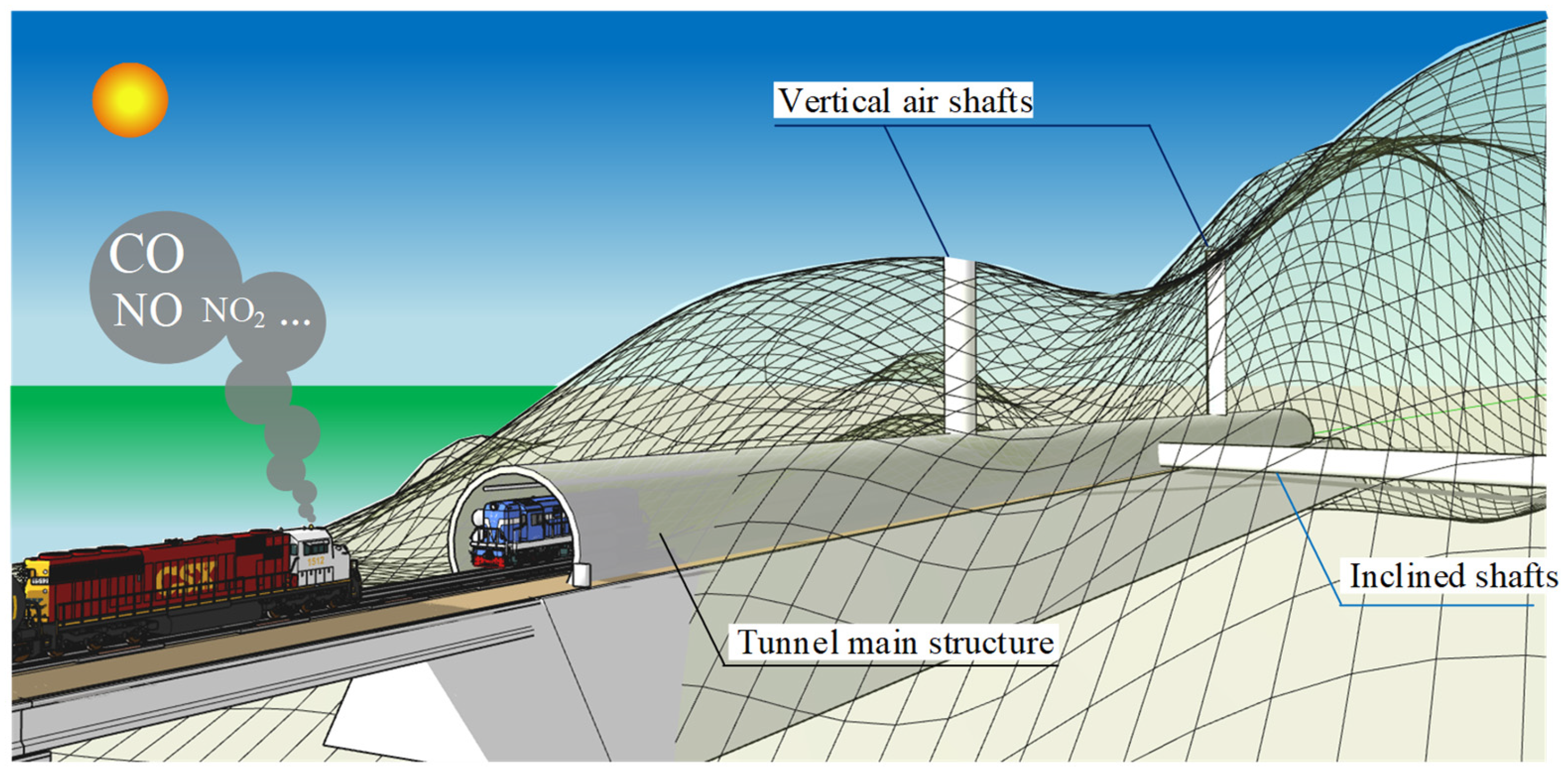
Tunnel ventilation structure refers to the spatial structure for the diffusion of emissions in the tunnel. Classic tunnel ventilation can be shown in Figure 2. These structures include both the tunnel main structure, vertical shafts, and inclined shafts used for auxiliary ventilation. Vertical shafts can introduce fresh air on the surface from outside the tunnel to the underground space and exhaust contaminated air from the tunnel. Moreover, vertical shafts may also help regulate the temperature and humidity in the tunnel, especially when fire accidents happen. Functioned as an important exhaust duct, vertical shafts provide favorable conditions for personnel evacuation and fire rescue [37]. Inclined shafts are set to ensure the tunnel adapts to the terrain conditions better. For example, during the construction of the tunnel in mountain areas, inclined shafts can be arranged along the mountain slope, which can avoid large-scale mountain excavation. In addition, an inclined shaft can also assist in construction transportation and serve as a transmission channel for personnel, equipment, and materials. Most importantly, inclined shafts can also improve ventilation flexibility. In some large-scale underground engineering projects, ventilation inclined shafts tend to be set in conjunction with ventilation vertical shafts [38], creating more complex ventilation networks so that the flexibility and reliability of ventilation systems can be improved.
The above ventilation structures are closely associated with the distribution pattern and natural diffusion patterns as well as the diffusion under ventilation conditions, thereby directly affecting the design of both gas monitoring schemes and ventilation systems within tunnels. Therefore, this paper classifies them as an important component of tunnel ventilation systems.

3.1.3. Sensors

As mentioned before, the exhaust gas emitted by diesel traction locomotives in tunnels contains Carbon Monoxide (CO), Carbon Dioxide (CO2), Sulfur Oxides (SOx), Nitrogen Oxides (NOx), Particulate Matter (PM) [31], and smoke and dust. Therefore, different gas sensors are often set in tunnels for different pollutants, such as Carbon Monoxide (CO) sensors, Carbon Dioxide (CO2) sensors, dust sensors, and sensors for monitoring combustible gases such as methane. In addition, since the temperature and humidity in the tunnel, the natural wind speed and direction, and the running condition of the train will affect the diffusion pattern of pollutant emissions and the ventilation effect in the tunnel, temperature and humidity sensors, wind velocity/direction sensors, visibility sensors, and train detection sensors will also be installed in the tunnel.
Sensors are usually set in all key areas of the tunnel, including the entrance, exit, and areas with slope changes and frequent human activities, to ensure comprehensive monitoring of the environmental conditions inside the tunnel. In the longitudinal axis of the tunnel, a group of sensors, including gas, temperature, and humidity sensors, is generally set up at a certain distance (such as 50 to 100 m) to monitor environmental parameters at different locations in the tunnel. The sensors should be evenly distributed across the cross-section of the tunnel. For example, sensors are installed at the top and side walls of the tunnel to comprehensively monitor the environmental conditions at different heights and locations within the tunnel. For double-track tunnels, sensors should be installed above each lane to ensure accurate monitoring of the environment in each lane. For the long tunnel, the tunnel can be divided into several monitoring sections according to its length and terrain conditions, and corresponding sensors can be set in each section. For areas prone to problems, such as poorly ventilated areas and areas near pollution sources, the number and density of sensors should be appropriately increased to strengthen monitoring of these key areas, ensuring that the monitoring data accurately reflects the ventilation efficiency and provides reliable data for the adjustment of the ventilation system. In addition, the installation location of the sensor should be convenient for staff to perform daily maintenance and repairs.

3.1.4. Programmable Logic Controller

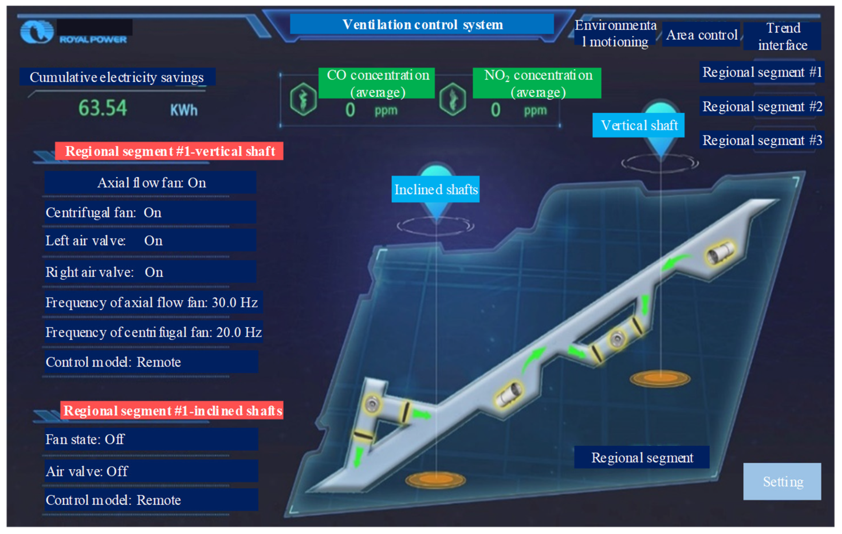
The programmable logic controller of the tunnel ventilation system is the core component to ensure the efficient ventilation and safe operation of the tunnel. It has centralized monitoring and intelligent control functions. In terms of monitoring, programmable logic controllers can collect real-time environmental data such as concentrations of Carbon Monoxide and Carbon Dioxide, temperature and humidity, wind velocity/direction, and visibility through the sensors in each section of the tunnel. These data can be directly illustrated on the screen of the control room so that staff can always keep track of the environmental conditions inside the tunnel. In terms of control functions, the central control system automatically adjusts the operation of ventilation equipment based on the collected data. When Carbon Monoxide concentrations exceed the threshold, the speed and airflow of the fans rapidly increase to accelerate the removal of harmful gases. If wind velocity/direction turns abnormal, ventilation equipment can be precisely controlled to change wind velocity/direction so that effective ventilation can be ensured. At the same time, a programmable logic controller supports remote control and automatic alarms. Staff can remotely operate ventilation equipment from the control room, improving emergency response speed, as shown in Figure 3. Once environmental parameters exceed safe limits, the system immediately issues an alarm to alert staff to take action in time, ensuring the safety of personnel and vehicles inside the tunnel and enabling intelligent, automated management of the tunnel ventilation system.

3.1.5. Auxiliary Ventilation Equipment

Auxiliary ventilation equipment of the tunnel is one of the important components to ensure the air quality and ventilation efficiency in the tunnel, including jet fans, air ducts, and air curtains.
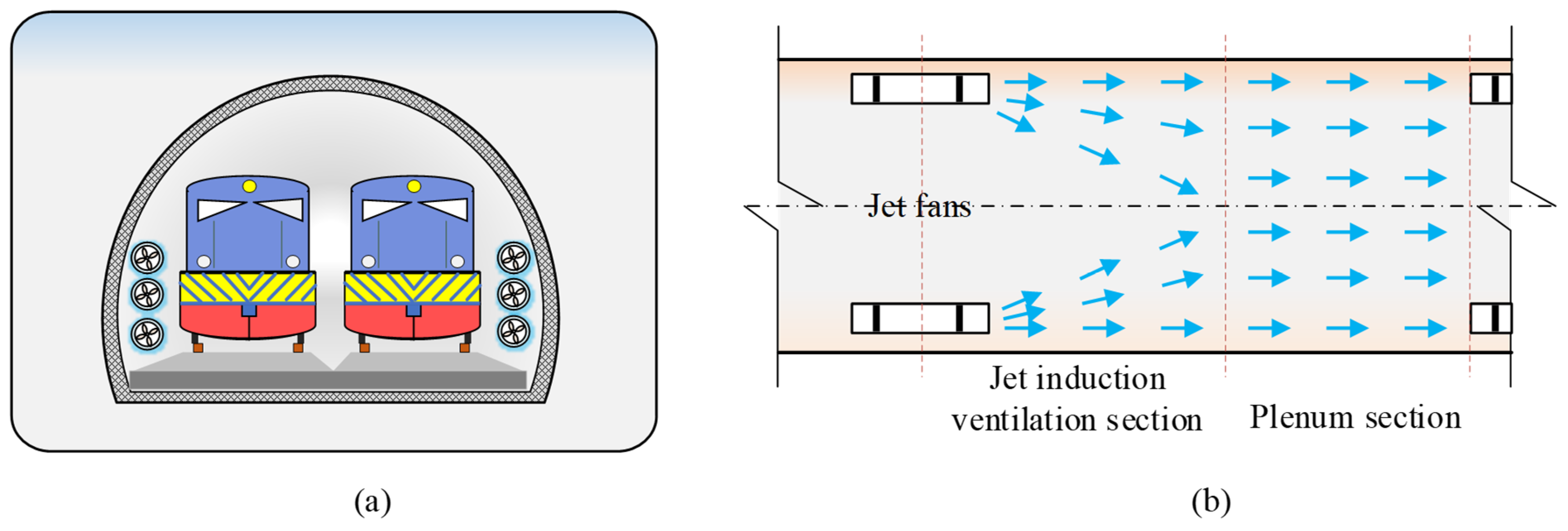
Jet fans are the most common auxiliary ventilation equipment and achieve ventilation by ejecting high-speed airflow and using the momentum of the airflow to induce and accelerate the flow in the surrounding area. It is flexible to install and typically set on the side walls of railway tunnels, as shown in Figure 4, featuring minimal impact on tunnel traffic, efficient energy savings, and no occupation of tunnel ground space. It is widely applied in tunnels of various lengths. Especially in the long tunnel, multiple jet fans can be arranged at regular intervals to promote air flow in a relay manner.
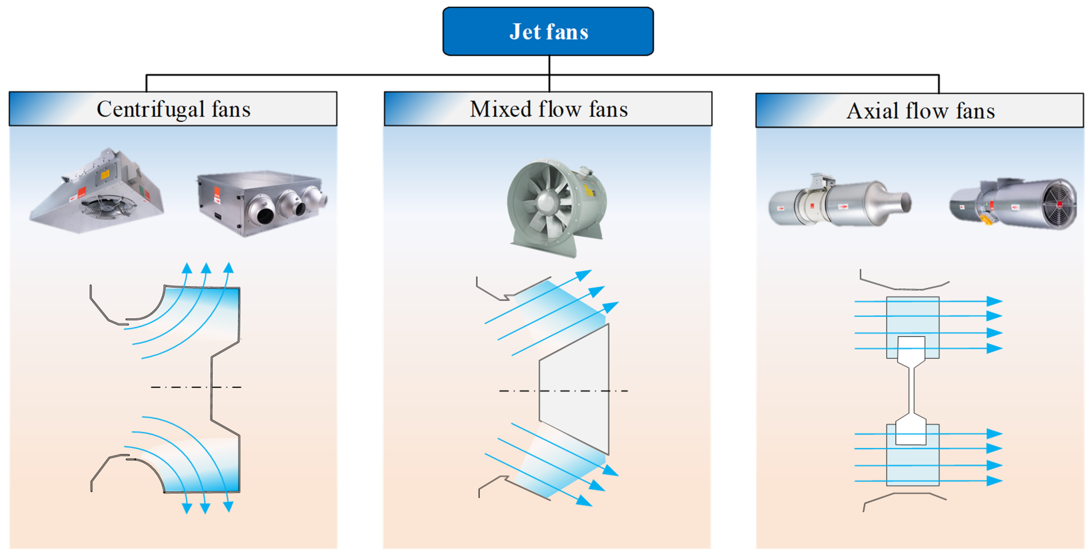
According to the different airflow patterns, jet fans can be classified into centrifugal fans, mixed flow fans, and axial fans, as shown in Figure 5. Axial flow fans enable gas to flow along the fan axis. Through the rotation of the impeller, mechanical energy is converted into the kinetic energy and pressure energy of the gas, thereby propelling the air flow. Axial flow fans feature high flow rates and moderate air pressure, which can meet the high air exchange requirements of tunnels. Different installation methods can be selected based on the specific conditions of the tunnel, such as horizontal or vertical installation, suitable for medium-to-short tunnels or tunnels with high ventilation requirements. It is commonly used as the main jet fan in tunnel ventilation systems. Centrifugal fans rely on the centrifugal force generated by the rotation of the impeller to throw gas from the center of the impeller to the edge, thereby imparting energy to the gas and achieving ventilation. These fans have high air pressure and can overcome significant ventilation resistance, making them commonly used in sections of tunnel ventilation systems that require overcoming high resistance. Mixed flow fans combine the characteristics of axial flow fans and centrifugal fans. The flow direction of the gas within the fan is between axial and radial, combining the advantages of the high flow rate of axial flow fans and the high air pressure of centrifugal fans, and having a wide performance range.
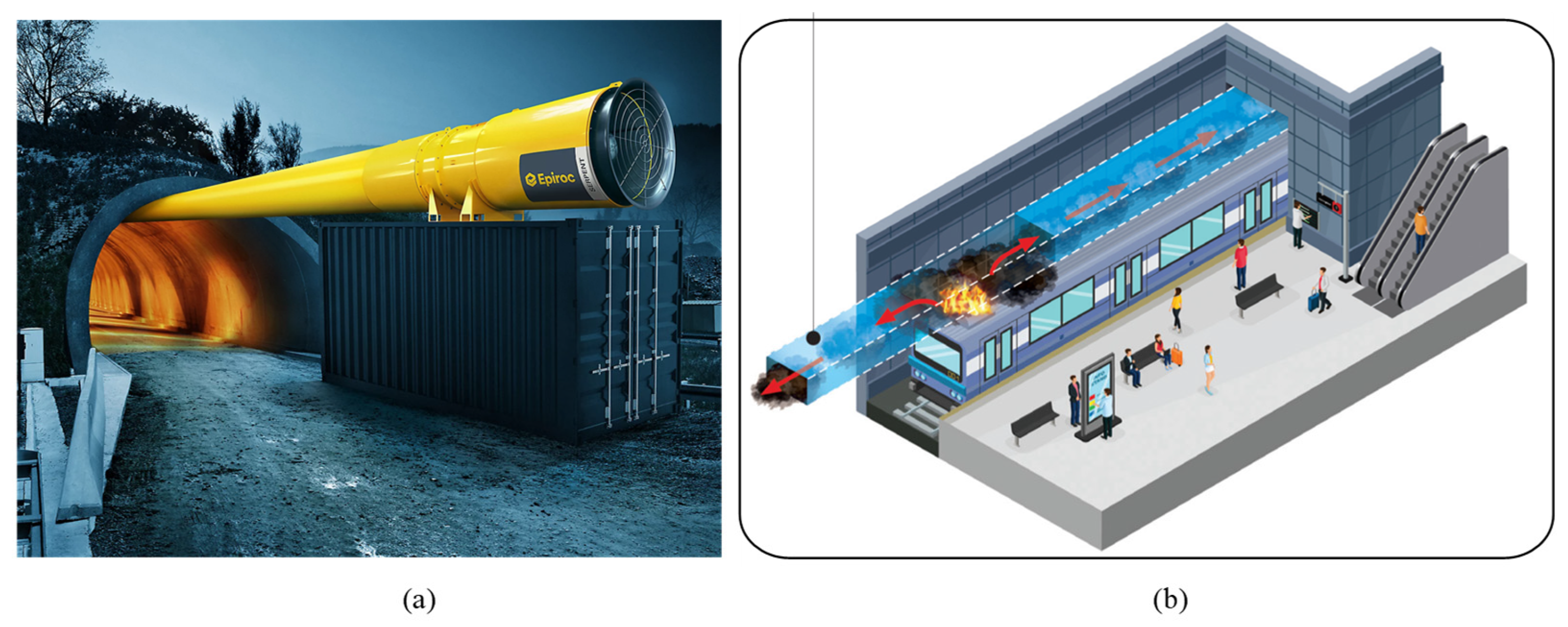
The air duct is also an important piece of auxiliary ventilation equipment. The air duct can deliver fresh air to specific areas of the tunnel or exhaust contaminated air from the tunnel. The typical layout of air ducts in a tunnel is shown in Figure 6a. Air ducts are generally made of steel plates or fiberglass materials with good sealing properties and corrosion resistance. In some large tunnels, main air ducts and branch air ducts are also installed to form a complex ventilation network.
Air curtains are installed at the entrances and exits of tunnels. As can be seen in Figure 6b, through ejecting high-speed airflow, an air curtain is formed to prevent polluted air from outside the tunnel from entering the tunnel so that heat and smoke from escaping can be prevented from inside the tunnel. Air curtains are energy-efficient and environmentally friendly and can effectively improve the ventilation environment in tunnels. These auxiliary ventilation devices work together to provide good ventilation conditions inside the tunnel, ensuring the safe passage of people and vehicles.

3.2. Classification of the Tunnel Ventilation System

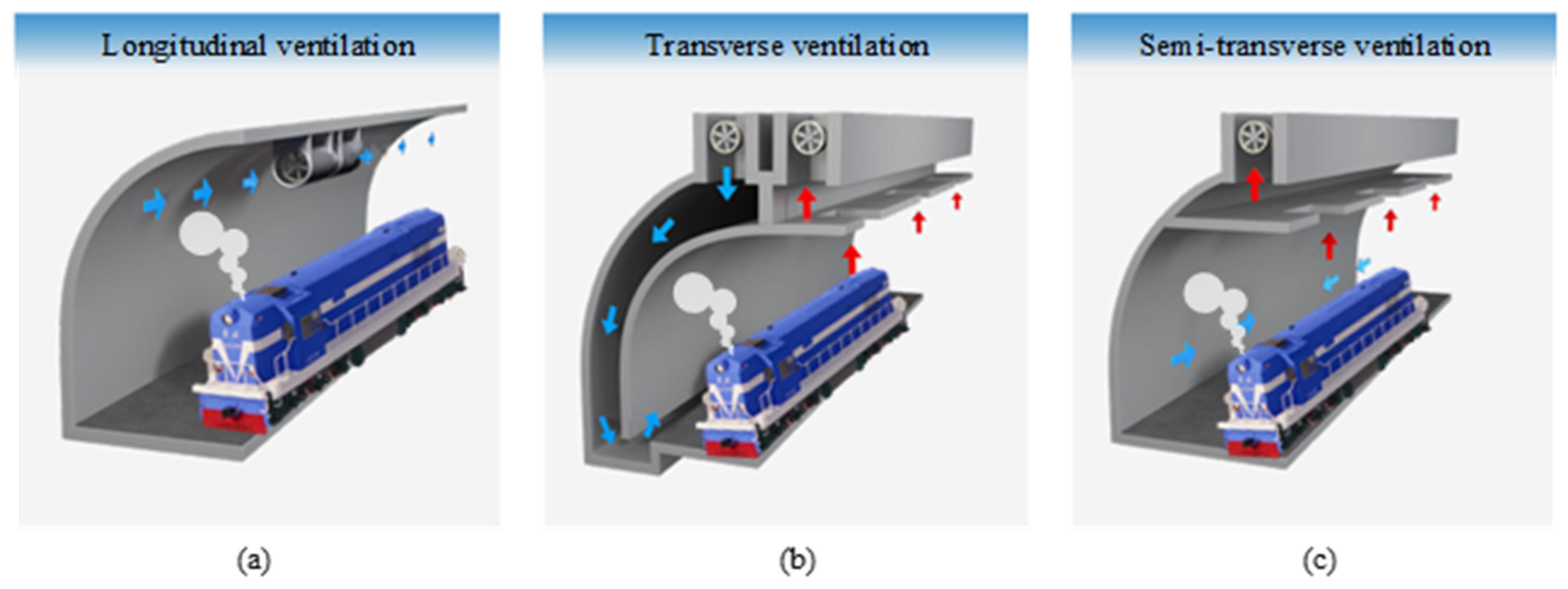
Based on different ventilation concepts, tunnel ventilation systems can generally be divided into three categories [43]: longitudinal ventilation [44,45], transverse ventilation [46], and semi-transverse ventilation [47,48], as shown in Figure 7. Longitudinal ventilation refers to the use of fans to blow polluted air from one end of a tunnel to the other and expel it from the tunnel. Therefore, longitudinal ventilation is also known as squeeze ventilation. Transverse ventilation refers to the discharge of smoke from the source and the intake of fresh air nearby. It is generally applicable to two-track traffic tunnels longer than 3000 m and should be equipped with air/smoke exhaust dampers that can be operated individually or in groups. Semi-lateral ventilation refers to the need to discharge flue gas from a location close to the emission source, while fresh air can be circulated by relying on the longitudinal pressure difference in the tunnel. With the widespread application of one-way tunnels, longitudinal ventilation has gradually become dominant, especially full-jet longitudinal ventilation. Full jet longitudinal ventilation refers to the installation of jet fans in tunnels. Jet fans use high-speed rotating impellers to suck in air, accelerate it, and then eject it from the outlet as high-speed airflow. The high-speed airflow generates a reaction force on the fan, pushing the surrounding air to flow in the direction of the jet, forming “induced airflow” that drives the overall airflow in the tunnel. Compared with full transverse ventilation or semi-transverse ventilation, full jet longitudinal ventilation has the advantages of convenient construction management and maintenance, as well as low operating costs [49]. Full jet longitudinal ventilation has now become the most widely used ventilation method in railway tunnel operations in China.
Tunnel ventilation can be classified into natural ventilation [50] and mechanical ventilation according to the ventilation method. Natural ventilation utilizes temperature and pressure differences between the inlet and outlet of a tunnel to create airflow, eliminating the need for fan equipment. However, it is inefficient at removing harmful gases and is only suitable for short tunnels. Long tunnels typically employ mechanical ventilation, including longitudinal, transverse, semi-transverse, and combined ventilation systems [51]. Auxiliary tunnels, such as inclined shafts, vertical shafts, cross passages, and parallel guide tunnels constructed during construction, can be fully utilized for ventilation during tunnel operation. Of course, whether mechanical ventilation should be installed in a tunnel requires comprehensive analysis and calculation, as well as experimental evaluation, considering factors such as the type of traction system, tunnel length, tunnel plan and profile, vehicle speed and density, and the topographical conditions at both tunnel portals.
Based on the level of automation and intelligence of tunnel ventilation systems, mechanical ventilation systems can be further classified into passive ventilation, active ventilation, and intelligent ventilation. Passive ventilation systems typically require continuous operation of ventilation equipment, resulting in significant energy consumption. Active ventilation systems can adjust ventilation conditions based on harmful gas concentrations or train operations, but they still have drawbacks such as frequent starts and stops, shortening equipment lifespan, and outdated operations causing energy waste. However, intelligent ventilation systems can utilize precise data from environmental monitoring systems and train detection systems, combined with optimization algorithms or pre-training, to quickly determine and control ventilation equipment to operate at optimal conditions, achieving ventilation objectives while balancing efficiency and energy conservation.

3.3. Energy Consumption of Different Ventilation Strategies

Different ventilation strategies significantly affect energy consumption and operational costs. Active ventilation, using mechanical systems like fans and air conditioning, offers precise control but is energy-intensive. In contrast, passive ventilation relies on natural airflow, reducing energy use but is limited by weather conditions and building design. Intelligent control systems can optimize both strategies by adjusting ventilation in real time, reducing energy consumption, operational costs, and indirect CO2 emissions, while maintaining comfort and sustainability.

4. Ventilation Standards for Diesel Locomotive Railway Tunnels

4.1. Primary Pollutant

As described in Section 3, diesel locomotives emit complex pollutant mixtures in railway tunnels, including nitrogen oxides (NOx), carbon monoxide (CO), carbon dioxide (CO2), sulfur dioxide (SO2), oxygenated volatile organic compounds such as formaldehyde (HCHO) and acetaldehyde (CH3CHO), and particulate matter (PM) from incomplete combustion. The ventilation system must maintain contaminant concentrations below occupational exposure limits (OELs) to (1) protect the physiological health of railway staff, passengers, and maintenance workers; and (2) minimize material degradation of tunnel linings and electromechanical systems caused by chemical corrosion, humidity, and thermal stress. Current international regulations exhibit significant discrepancies in OEL thresholds for these hazardous air pollutants.
According to engineering practice and related research, when ventilation systems are designed to maintain NOx concentrations within permissible hygiene standards, the concentrations of other pollutants inherently comply with regulatory requirements. Therefore, in tunnel ventilation design, the attainment of NOx concentration standards is generally taken as the design basis. Since NOx is difficult to accurately and directly detect, the Code for Design of Railway Tunnel Ventilation Systems (TB 10068-2024) [52] stipulates that when measuring the concentration of NOx, the vacuum sampling Saltzman method is used to convert all NOx into NO2, thereby obtaining the concentration of the main pollutant index NOx in diesel engine exhaust.

4.2. Ventilation Standards of the Main Countries Around the World

Countries worldwide OELs for hazardous substances based on their specific conditions. OELs represent the permissible exposure levels that, under long-term and repeated occupational exposure, do not cause harmful effects to the majority of workers. Typically, OELs include three categories: permissible concentration-time weighted average (PC-TWA), permissible concentration-short term exposure limit (PC-STEL), and maximum allowable concentration (MAC). The specific definitions and terminologies vary across different national standards.
  • PC-TWA: The average allowable exposure concentration over an 8 h workday or a 40 h workweek, calculated using time weighting.
  • PC-STEL: The maximum allowable concentration for short-term exposure (15 min), provided that the PC-TWA is not exceeded.
  • MAC: The peak concentration that must not be exceeded at any time during the workday in the workplace.

4.2.1. Chinese Standards

In China, the control requirements for pollutant concentrations such as CO and nitrogen oxides are primarily stipulated in national standards and (transportation) industry regulations. The specific provisions in these standards are listed in Table 1.
The Allowable Concentration and Measurement of Locomotive Exhaust in Railway Operating Tunnel (TB/T 1912-2005) [53] stipulates that the PC-TWA and PC-STEL of carbon monoxide shall not exceed 30 mg/m3 and 100 mg/m3, respectively. For nitrogen dioxide, these limits are set at 10 mg/m3 and 20 mg/m3. The Guidelines for Design of Ventilation of Highway Tunnels (JTG/T D70/2-02-2014) [54] considers the influence of tunnel length and establishes different concentration requirements for CO and NO2 in tunnels of varying lengths.
Based on findings from the research project Key Technologies for Ventilation in Long and Large Tunnels, it was recognized that railway tunnels may contain not only quartz dust but also organic dust (e.g., plant- and animal-based particulates), as observed in the Dayaoshan Tunnel. Consequently, the Code for Design on Operation Ventilation of Railway Tunnel (TB 10068-2010) [55] introduced control requirements for organic dust concentrations. Furthermore, following the 2019 revision of Occupational Exposure Limits for Hazardous Agents in the Workplace—Part 1: Chemical Hazardous Agents (GBZ 2.1-2019) [56] which established standards for multiple dust types including calcium carbonate dust, the latest Code for Design of Railway Tunnel Ventilation (TB 10068-2024) [52], revised in 2024, has further refined these requirements. Notably, the current standard [52] incorporates altitude considerations, stipulating that the maximum allowable CO concentration shall not exceed 20 mg/m3 for tunnels at 2000–3000 m altitude, and is further reduced to 15 mg/m3 for altitudes above 3000 m. This establishes an inverse relationship between permissible CO levels and elevation, representing a regulatory enhancement absent in prior versions.
For better understand of the latest Chinese standard (TB 10068-2024) [52], a simple comparative analysis of a 2 km road tunnels, Tunnel A at sea level (0 m) and Tunnel B at high altitude (3000 m), is conducted in this subsection. The core difference is the air density, which decreases from 1.225 kg/m3 at sea level to 0.909 kg/m3 at high altitude. This change drives two critical divergences in the design according to the new standard. First, the required air volume for Tunnel B increases by approximately 40% (e.g., from 300 m3/s to 420 m3/s) to compensate for higher vehicle emissions in the thin air. Second, the performance of individual jet fans is degraded, as their thrust is proportional to air density; the same fan produces about 26% less thrust at high altitude. Consequently, the final design for Tunnel B must compensate for this “double penalty”—a higher airflow target with less efficient equipment. This necessitates a significantly larger ventilation system, requiring roughly 40% more jet fans than the sea-level design to achieve the same level of safety and air quality.
Table 1. Permissible concentration limits of pollutants in Chinese standards (OELs, mg/m3).
Year 2005201420222024
Standard Allowable Concentration and Measurement of Locomotive Exhaust in Railway Operating Tunnel (TB/T 1912-2005) [53]Guidelines for Design of Ventilation of Highway Tunnels (JTG/TD70/2-02-2014) [54]The Coal Mine Safety Rules (2022) [57]Code for Design on Operation Ventilation of Railway Tunnel (TB10068-2024) [52]
COPC-TWA3020
PC-STEL100172.5 (20 min, L ≤ 1000 m)
115.0 (20 min, L > 3000 m)
30
MAC27.5— (H< 2000 m)
20 (2000 m ≤ H ≤ 3000 m)
15 (H > 3000 m)
NO2PC-TWA105
PC-STEL201.88 (20 min)10
MAC4.7
NOPC-TWA 15 (H < 3000 m)
PC-STEL
MAC
Quartz dustPC-TWA 8 (MSiO2 < 10%)
1 (MSiO2 > 10%)
PC-STEL 10 (MSiO2 < 10%)
2 (MSiO2 > 10%)
MAC
Marble dust
(Calcium carbonate, CAS: No.1317-65-3)
PC-TWA 4
PC-STEL
MAC
Plant- and animal-based particulatesPC-TWA 2
PC-STEL 4
MAC
Other dustPC-TWA 8
PC-STEL
MAC
Note: L represents tunnel length; H denotes tunnel altitude.

4.2.2. US Standards

The Occupational Safety and Health Administration (OSHA) is the federal agency responsible for worker safety. It establishes permissible exposure limits (PELs) for various workplace pollutants [58]. These limits incorporate standards from the California Division of Occupational Safety and Health (Cal/OSHA) [59], recommended exposure limits (RELs) by the National Institute for Occupational Safety and Health (NIOSH) [60], and threshold limit values (TLVs) by the American Conference of Governmental Industrial Hygienists (ACGIH) [61], as listed in Table 2.

4.2.3. German Standards

The German Committee on Hazardous Substances (AGS) has established the Technical Rules for Hazardous Substances (TRGS 900-2024) [62], which incorporate the latest technological, occupational medical, and hygienic knowledge regarding hazardous substances, including their classification and labeling. These rules are published by the German Federal Ministry of Labor and Social Affairs (BMAS) in the Gemeinsames Ministerialblatt (GMBl) [63].
The Commission for the Investigation of Health Hazards of Chemical Compounds in the Work Area of the German Research Foundation (DFG) [63] has developed workplace exposure limits known as MAK values. The MAK represents the average concentration over a work shift, not a single measurement. The concentration limits for typical pollutant emissions specified by these two organizations are presented in Table 3.

4.2.4. The European Union Standards

The European Union places great emphasis on protecting the health of workers from chemical risks in workplaces [64], the related regulations can be found in the Council Directive 98/24/EC [65]. After multiple revisions, the current occupational exposure limits are shown in Table 4.

4.2.5. World Health Organization (WHO)

In 2021, WHO updated the WHO Global Air Quality Guidelines (AQGs) [66], which establish target air quality levels for protecting global public health. These AQGs are commonly used as reference concentrations to evaluate worker safety exposure and potential health impacts. The specified air quality limits are presented in Table 5.
In addition to the standards mentioned above, several other codes also specify requirements for tunnel ventilation. The TSI-SRT [67] primarily focuses on interoperability and safety requirements for railway tunnels in the European Union. Although it does not provide detailed regulations on pollutant gas concentrations, it sets out basic requirements to ensure safe air quality and ventilation systems, which help control the spread of smoke and toxic gases during a fire, thus reducing exposure to harmful gases such as carbon monoxide. NFPA 130 [68] provides specific requirements for fixed-guideway transit systems, including railway tunnels. In emergency situations, such as a fire, it mandates that the concentration of toxic gases (e.g., carbon monoxide) within the tunnel must be controlled to prevent harmful exposure to passengers and rescue personnel. This is achieved by maintaining efficient ventilation and air extraction systems. The concentration of carbon monoxide (CO) in the air should not exceed 1150 ppm during the first 6 min of exposure, and visibility in public areas should be at least 10 m, which should be maintained at platform and concourse levels. The smoke extraction height for platforms and concourses should be at least 2.5 m [69]. UIC [70] provides guidelines for the safety of railway tunnels, including pollutant control. It emphasizes controlling the concentration of toxic gases, particularly carbon monoxide (CO), and maintaining safe levels during emergencies. Similar to NFPA 130, UIC also recommends controlling harmful gas concentrations at safe levels to ensure safe evacuation and rescue operations.
Key observations from the pollutant concentration limits in these national standards include the following: (1) Among various pollutants, CO, NO, and NO2 are consistently regulated, indicating their critical importance in ventilation design and research; (2) PC-TWA and PC-STEL are the predominant metrics adopted across standards, while MAC requirements are often absent; (3) Additional pollutants such as marble dust and organic particulates may occur in tunnels and must be considered in ventilation design; (4) Tunnel length and altitude significantly influence concentration control requirements, with longer and higher-altitude tunnels demanding stricter ventilation standards.

4.3. Comparative Analysis

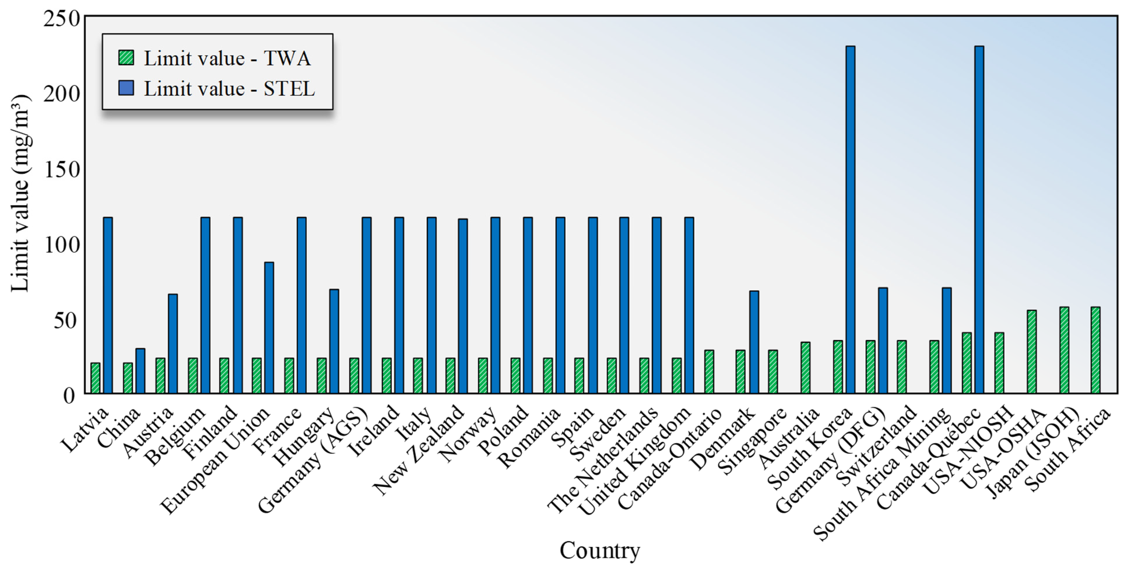
Figure 8 shows that China [52] impose the most stringent CO controls, setting PC-TWA at ≤20 mg/m3. China’s PC-STEL limit (≤30 mg/m3) also proves stricter than other nations, where typical limits exceed 50 mg/m3 or remain unspecified (e.g., Singapore [71], Australia [72], US [61], Japan [73]).
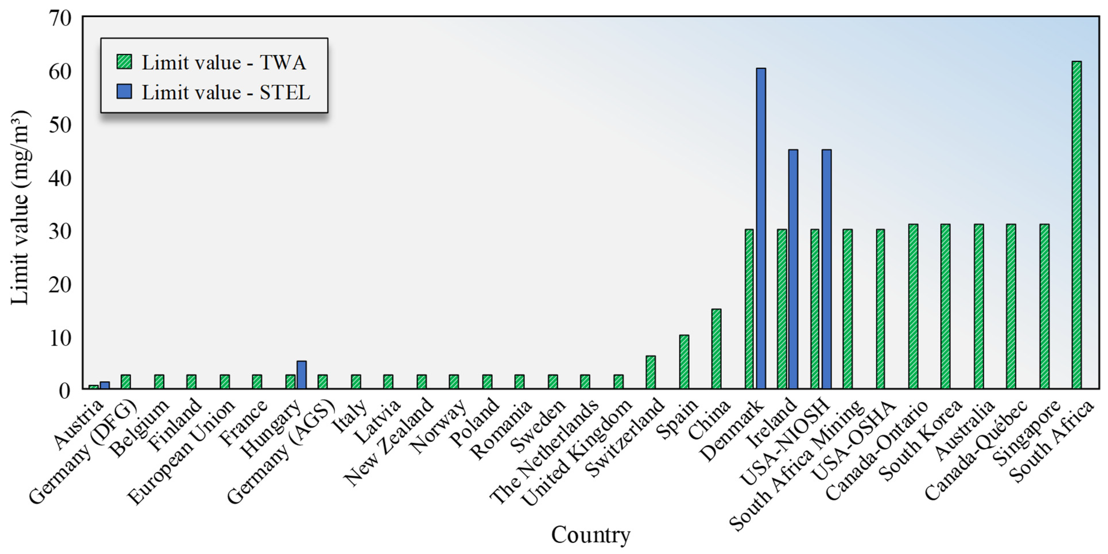
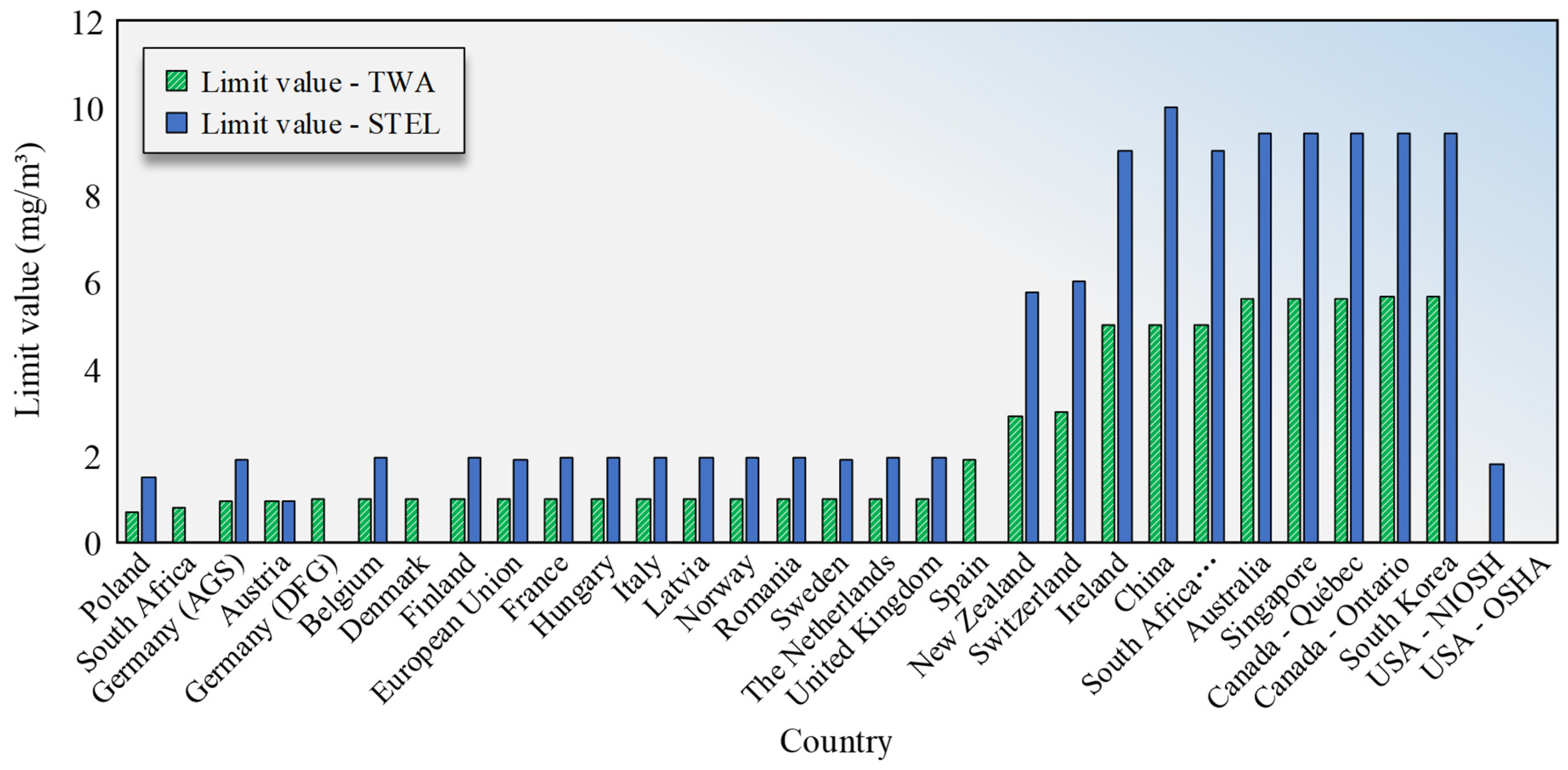
Figure 7 and Figure 8 illustrate the concentration limits for CO, NO, and NO2 stipulated in the specifications of several major countries worldwide. Only PC-TWA and PC-STEL values are shown in those figures, as MAC requirements appear in few regulations. For comparison, the data are sorted by PC-TWA stringency, with the leftmost position indicating the strictest standards.
Figure 9 reveals that European countries (Germany [63], Norway [74], Poland [75], UK [76]) maintain rigorous NO limits, generally requiring PC-TWA ≤ 2.5 mg/m3. Germany’s DFG standard [62] is exceptionally strict at ≤ 0.63 mg/m3. In contrast, Denmark, US [60], Canada [77,78], and Australia [79] apply more lenient limits (PC-TWA ≤ 30 mg/m3). China’s standard [52] (PC-TWA ≤ 15 mg/m3) falls between these groups, slightly exceeding Spain’s ≤ 10 mg/m3 [80]. Notably, only Germany’s DFG [62] and AGS [63] standards establish strict PC-STEL limits for NO.
Figure 10 shows that the comparative results of NO2 concentration control requirements among countries resemble those of NO. The presented nations can be broadly categorized into high-stringency and low-stringency groups. The high-stringency group, represented by European countries including Poland [75], Germany [63], Finland [81], Italy [82], the Netherlands [83], and the UK [76], typically requires NO2 PC-TWA and PC-STEL concentrations to remain below 0.96 mg/m3 and 1.91 mg/m3, respectively. In contrast, other European nations such as Spain [80], Switzerland [84], and Ireland [85] maintain more lenient NO2 control standards, as does China’s standard [52]. Nevertheless, these countries’ standards remain more stringent than those of Australia [72,79], Singapore [71], South Korea [86], and Canada [77,78]. Notably, the US standard [60] (NIOSH) only specifies a NO2 PC-STEL limit of ≤1.91 mg/m3, which aligns with French [87] and Italian [82] regulations.
Comparative analysis of international tunnel pollutant concentration limits reveals that EU countries, particularly the UK [76] and France [87], impose significantly stricter controls on all three aforementioned pollutants than other nations.
In contrast, countries such as the US [60] and Canada [77,78] maintain more lenient regulatory standards. This divergence may be attributed to distinct geographical and climatic conditions. The prevalence of long and deeply buried tunnels in European countries results in limited natural pollutant dispersion, necessitating stricter limits and greater reliance on mechanical ventilation systems. Conversely, the vast territory and relatively low population density in North America enhance the environmental capacity for pollutant dilution, thereby justifying more permissive standards. Comparative analysis of regional standards within Canada reveals that Quebec [78] maintains more lenient CO concentration limits than Ontario [77], suggesting potential economic considerations in standard-setting. Regions with developing economies often demonstrate greater reliance on resource extraction and freight transport, where stringent emission limits may necessitate increased infrastructure investments and potentially constrain local transportation economics. This observation finds partial support in African normative data, where only economically advanced South Africa [88] has established relevant standards. Consequently, national determinations of tunnel pollutant concentration limits must consider both population density and local economic conditions, along with tunnel infrastructure development levels.
Moreover, political decision-making and public awareness, along with scientific research and data foundations, also exert significant influence. Nations that prioritize environmental protection and public health are often driven by policy to establish more stringent limit values. Societies with high environmental awareness and strong health concerns tend to generate substantial public pressure, prompting governments to elevate regulatory standards. Countries possessing comprehensive local epidemiological survey data and toxicological studies are able to develop more targeted limit values based on exposure-response relationships within their populations. For complex mixtures such as diesel engine emissions, health risk assessments continue to evolve, and differences in the pace and extent of adopting the latest scientific findings across countries further contribute to divergent standards.
In summary, the determination of pollutant concentration limits in tunnels within any country must take into account not only its natural environment, economic development status, and level of tunnel infrastructure construction but also factors such as political decision-making, public awareness, and scientific research and data foundations.

5. Research Methods Applied for Railway Tunnel Ventilation Analysis

Pollutant gases emitted by diesel locomotives constitute part of the fluid within tunnels. Their concentrations vary with airflow dynamics. The diffusion and flow patterns of these fluids through tunnel structures serve as critical references for selecting ventilation methods and determining vent locations, fan quantities, and installation positions. To investigate these flow characteristics, theoretical analysis, simulation, scaled model testing, and field experiments are widely employed.

5.1. Theoretical Analysis

Theoretical calculations typically assume tunnel air as an ideal fluid: inviscid, incompressible, and steady-flow. Using fluid mechanics principles, airflow rates and pressure differentials are computed to establish baseline ventilation design parameters.
(1)
Dilution Theory
If the ventilation requirements of the tunnel are calculated directly based on the traditional pollutant emission standards for tunnels, the calculation results will far exceed the actual ventilation needs of the tunnel. Accurate pollutant concentration data is necessary to scale ventilation systems appropriately. For CO emissions from diesel locomotives, the required airflow to achieve the target dilution can be calculated as
Q C O = 1 3.6 × 10 6 × q C O f a f d f h f i v L × m = 1 n   N m f m      
Q reqCO   = Q C O δ × P 0 P × T T 0 × 10 6
in which Q C O is CO emission rate (m3/s); Q reqCO   represents required air volume for CO dilution (m3/s);   δ represents CO Design concentration (ppm); P 0 represents standard atmospheric pressure (Pa); P represents tunnel atmospheric pressure (Pa); T 0 represents standard temperature (K); T represents summer temperature (K); q C O represents Baseline CO emission rate (m3/s); f a represents vehicle condition coefficient; f d represents vehicle density coefficient; f h represents altitude coefficient; f i v represents grade-speed coefficient;   N m represents traffic volume for vehicle type m (vehicle/h);   f m represents vehicle type coefficient for vehicle type m; n represents the number of vehicle categories.
(2)
Piston Effect Theory
For longitudinal ventilation systems, the piston effect theory assumes pollutants are “pushed” through the tunnel. The required ventilation rate can be calculated by
Q = K i 1 v m v T F L T t q
in which Q represents the ventilation air volume in railway (m3/s); K i represents the piston wind correction coefficient; v m represents the piston wind velocity (m/s); v T represents the train speed (m/s); F represents the tunnel cross-sectional area (m2); L T represents the tunnel length (m); t q represents the ventilation and smoke extraction time (s).
The piston wind velocity in Equation (3) can be calculated using either steady or unsteady flow methods:
  • Steady flow calculation
v m = v T 1 + 1 + ξ m K m 1 1 ± ξ n v n 2 K m v T 2 / ξ m K m 1
K m = N l t / ( 1 α ) 2
N = 0.807 α 2 1.322 α + 1.008 + λ h l t d h / l t
d h = 4 ( F f t ) / ( S + S T 2 a )
2.
Unsteady flow calculation
v m = v T 2 A C + 2 A C e t B 2 4 A C C B + B 2 4 A C C B B 2 4 A C e t B 2 4 A C K m > ξ m
v m = v T 2 A C + 2 A C e t B 2 + 4 A C C B + B 2 + 4 A C C B B 2 + 4 A C e t B 2 + 4 A C K m ξ m
in which K m represents the piston wind effect coefficient; N represents the train drag coefficient; l t represents the train length (m); α represents the blockage ratio; λ h represents the frictional resistance coefficient of annular airflow; d h represents the equivalent diameter of annular space in meters (m); S represents the tunnel wetted perimeter (m); S T represents the train cross-section perimeter (m); a represents the train width (m); ξ m represents the resistance coefficient of tunnel sections excluding annular space; Parameters A, B, C are calculated based on K m ,   l t , l T ,   α , and ξ m .
The tunnel ventilation design process involves first determining the piston wind velocity, then calculating the required smoke extraction length based on this velocity, and finally obtaining the required number of jet fans or ventilation capacity according to the Design Code requirements. The steady flow theory has been widely used in China since the 1960s and 1970s and remains in application today. Unsteady flow calculations, which account for temporal variations in piston wind characteristics, provide more scientifically sound results for piston wind pressure calculations in non-extra-long tunnels.
Theoretical calculations form the basis for construction ventilation scheme design, but the reliability of these calculations depends critically on accurate determination of key parameters including required air volume, air leakage rate, and ventilation resistance. To improve calculation accuracy, the design process must comprehensively consider factors such as the tunnel project’s geographical environment, climatic conditions, and engineering characteristics, allowing for appropriate adjustments to ventilation parameters to determine optimal ventilation solutions.

5.2. Scale Model Experiments

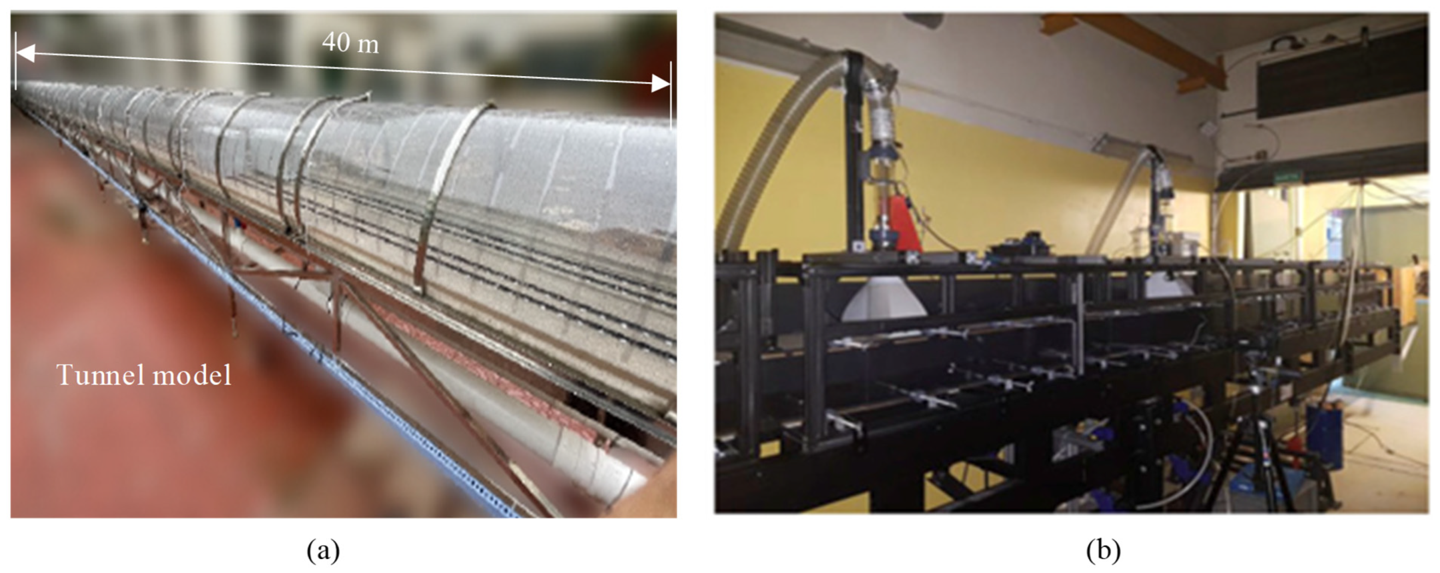
Full-scale or in situ tunnel ventilation tests are difficult to implement widely due to high costs and multiple risk factors. Typically, scaled tunnel models can be constructed based on similarity theory for ventilation research. For instance, Chen et al. [38] conducted a 1:45 scale model (Figure 11a) to study natural diffusion patterns of pollutants from diesel locomotives, considering tunnel gradient effects, and found smoke generally diffused toward higher entrances. To investigate the control of smoke propagation in transversely ventilated tunnels, Chaabat et al. [89] established a 1:25 scaled tunnel model, as shown in Figure 11b. Mechanical equipment like fans can also be incorporated in scaled models, Tao et al. [90] built a 65 m long 1:50 model to examine smoke and velocity field distributions during train approach and stopping at rescue stations, analyzing mechanical ventilation’s impact on cross-passage smoke control. Zhang et al. [91] conducted a 38 m long 1:20 model to study jet fan pressure effects on airflow distribution in tunnels with exit ramps. Scaled modeling also applies to emergency scenarios like fires. Tanaka et al. [92] conducted fire tests in a 1:20 tunnel model, systematically evaluating how wall thermal properties affect critical fire wind speed and back layering distance. Cheng et al. [93] employed 1:15 scaled interconnected tunnel models to simulate fire scenarios, analyzing smoke distribution patterns from various ignition points. Zhang et al. [94] similarly used 1:15 models to investigate longitudinal ventilation and transverse exhaust effects on temperature distribution. Mei et al. [95] revealed multi-smoke-exhaust coupling mechanisms and smoke layer evolution through 1:20 model tests. Additionally, scaled experiments can examine temperature distributions at varying longitudinal distances from fire sources [96], providing theoretical foundations for enhancing fire safety in long tunnels.
In summary, scaled models can be effectively employed to study various tunnel ventilation scenarios while incorporating different ventilation system components such as fans and ducts. These models serve for both localized ventilation analysis and overall system efficiency evaluation. Typical scale ratios range from 1:10 to 1:50, effectively balancing experimental feasibility with result accuracy. The scale of 1:30 is often used for long tunnels or complex shaft structures to optimize space utilization, while 1:20 scale proves suitable for most full-section ventilation studies by adequately simulating airflow patterns. The 1:10 scale, though more costly, provides higher precision for specialized applications. However, while scaled experiments can simulate diverse ventilation conditions, their results depend on similarity law conversions and model calibration, potentially limiting their ability to fully represent universal patterns in actual tunnel ventilation scenarios.

5.3. Field Tests

Field testing remains the optimal approach for studying, optimizing, and validating tunnel ventilation designs as it incorporates actual tunnel conditions, including geometric dimensions, wall roughness, and train-induced piston effects. Environmental parameters such as temperature, humidity, and air pressure can be automatically measured and incorporated into calculations without requiring artificial boundary conditions. Real traffic conditions can also be simulated, making field tests particularly valuable for complex, large-scale tunnel projects.
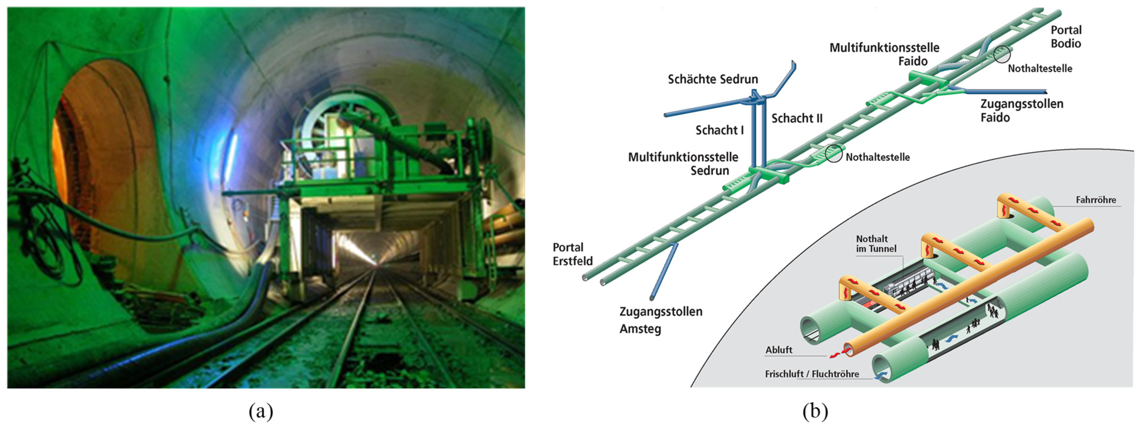
The Gotthard Base Tunnel is a world-renowned ultra-long railway tunnel and a quintessential cross-border strategic engineering project. As shown in Figure 12, it consists of twin 57 km tubes with 40 m cross-passages every 325 m serving as emergency exits. The tunnel must withstand significant pressure fluctuations from trains operating at 250 km/h and harsh conditions, including salt deposits, brake dust, soot, and wear materials. Its ventilation system employs longitudinal zoning with five independent 10–12 km segments, featuring reversible jet fans, intelligent control systems, bidirectional supply–exhaust airflow, and dynamic flow regulation.
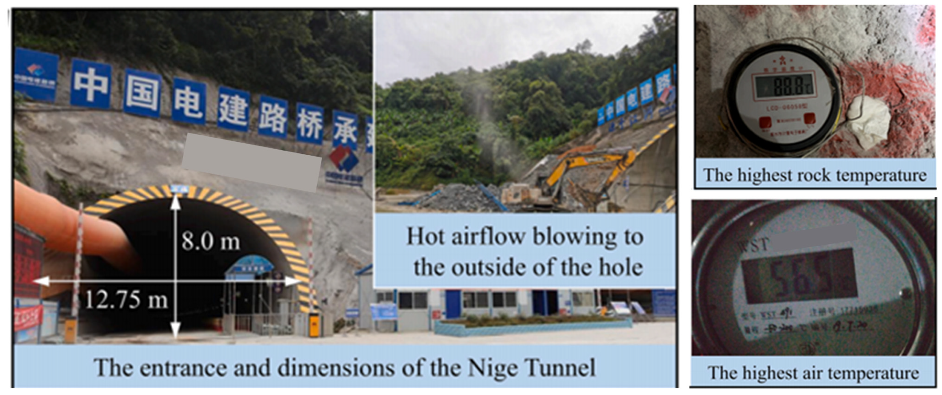
High geothermal tunnels represent another category of complex tunnel engineering projects. Tunnels with surrounding rock temperatures exceeding 30 °C are typically classified as high geothermal tunnels, with several such tunnels constructed worldwide [98,99]. For these environmentally challenging tunnels, field testing constitutes an essential research approach. Huang et al. [99] conducted field investigations on ventilation design in the high-temperature Nigua Highway Tunnel (Figure 13), monitoring temperature distributions at critical cross-sections and cooling performance data while simulating various construction conditions. Their work developed a convolutional neural network method for temperature prediction and created a dedicated mechanical ventilation cooling test platform for high-temperature tunnels.
Metro and highway tunnels with complex spatial configurations also require field testing due to their high passenger densities and variable traffic conditions. These research findings can still provide valuable insights for current ventilation issues in diesel locomotive railway tunnels. Moreno et al. [100] performed field ventilation monitoring along Barcelona Metro Line L2 (In total of 13.1 km in length), comparing air quality under mechanical ventilation versus pure piston effect conditions across 10 stations. Fang et al. [101] identified a distinct low-velocity “dead zone” 35–40 m ahead of cross-passages in the Huaying Mountain twin-tunnel complex through field measurements, where airflow velocities dropped significantly and pollutant concentrations increased markedly compared to other sections. Qian et al. [102] conducted field monitoring at multiple locations in the Qinling Tunnel Group (Figure 14), performing real-time measurements of traffic flow and environmental parameters. Their study analyzed the distribution patterns and temporal evolution of pollutant concentrations and visibility, quantitatively establishing correlations between traffic volume and air pollution levels. These findings identified key control parameters for the design and management of ventilation systems in extra-long tunnels as well as diesel locomotive railway tunnels.
Field testing remains the most effective approach for tunnel ventilation research, particularly for large-scale projects with complex spatial configurations and environmental conditions. These tests provide accurate boundary conditions and environmental parameters for ventilation design. However, field testing requires optimized experimental designs and must account for practical limitations. For instance, in diesel locomotive railway tunnels, jet fan systems cannot guarantee uniform velocity distributions across full tunnel cross-sections, and measured results only represent local airflow velocities at monitoring points [103].

5.4. Numerical Simulation

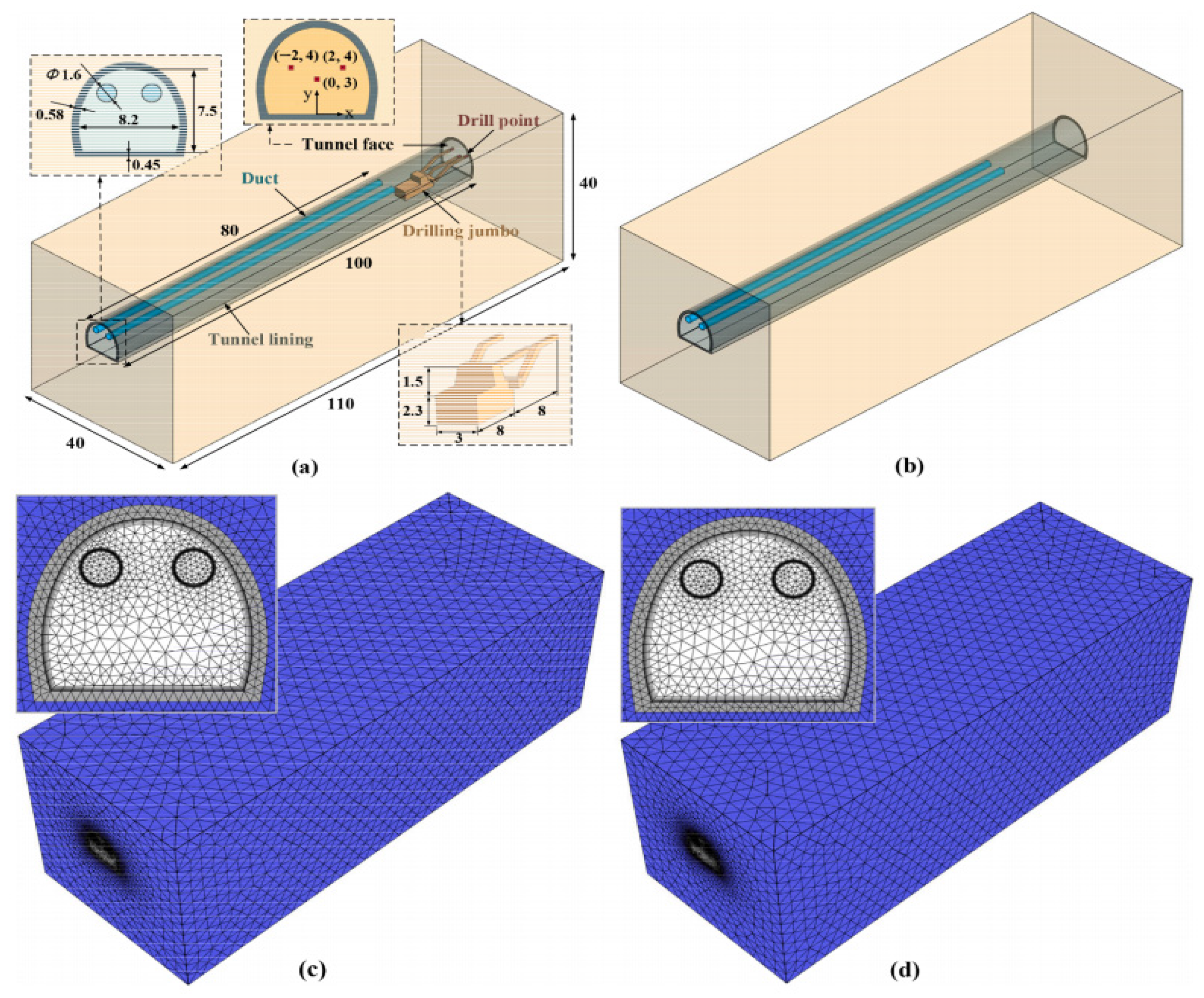
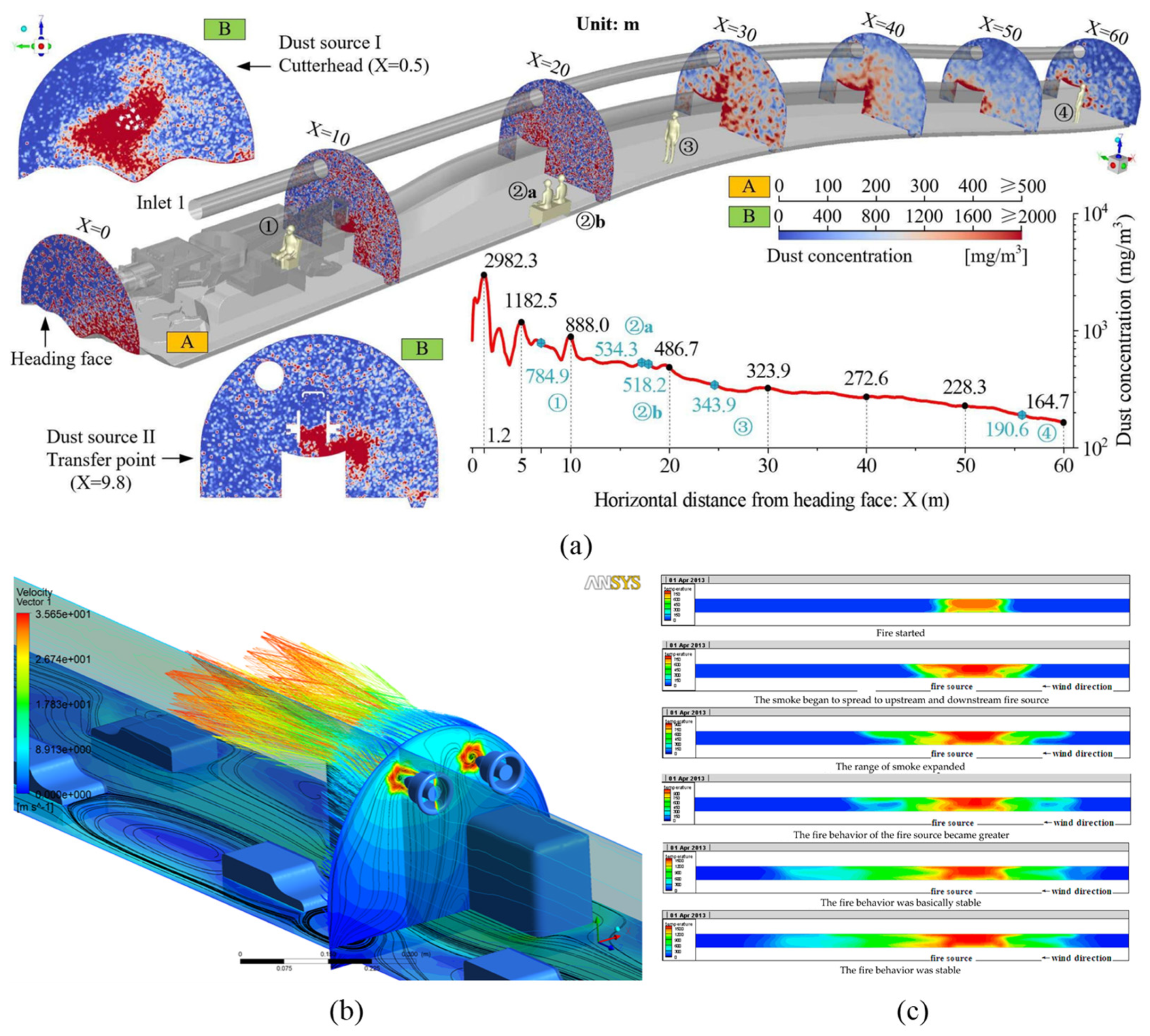
Traditional ventilation design relying on empirical formulas and physical modeling faces limitations in cost, duration, and flexibility for complex scenarios. The development of Computational Fluid Dynamics (CFD) has provided new approaches for detailed investigation of fluid flow characteristics, leading to the creation of various commercial software including AIRPAK (US), CFX (ANSYS), FDS (US), Fluent (ANSYS), OpenFOAM (US), COMOSAL (Sweden), SES (US), STAR-CD (STAR-CCM+), and IDA TUNNEL (Sweden). CFD simulations offer advantages in prediction accuracy, multi-physics coupling, and rapid design validation, effectively modeling gas dispersion [104], smoke movement [105], and temperature distribution [27,93] in tunnels, mines, and subways. As shown in Figure 15 [27], the software enables modeling of actual ventilation scenarios, incorporating detailed components such as ventilation ducts and fans [106]. For boundaries with complex fluid variations, simulation accuracy can be enhanced through optimized modeling and mesh refinement techniques [107]. This technology has been widely applied to tunnel construction [108], operation [109], and emergency scenarios [27,110,111,112], as shown in Figure 16.
Shorab Jain et al. [111] employed CFAST and CFX software to model a 150 m-long rectangular tunnel with an 80 m2 cross-sectional area, analyzing fire-induced temperature and velocity profiles while validating the simulation results. Christophe Ars et al. [113] validated ventilation hypotheses through OpenFOAM mine simulations. Su et al. [112] determined optimal ventilation schemes for fire scenarios using SES software. Wei et al. [114] investigated the ventilation cooling process in the Xiadian Gold Mine excavation tunnel using COMSOL software, examining the effects of tunnel cross-sectional area, airflow-to-area ratio, and temperature difference on cooling efficiency. By integrating empirical formulas with intake air temperature equations, they determined the maximum permissible intake air temperature for safe working conditions. Zhang et al. [115] conducted numerical simulations using FDS to investigate temperature field distributions during flame impingement on tunnel ceilings, with particular focus on analyzing the influence of fire source distance on maximum ceiling temperatures. Amouzandeh et al. [116] predicted temperature distributions in tunnel fires through CFD. Critical ventilation parameters, including critical velocity [117], backlayering length [118], ceiling temperature [119], and heat release efficiency [120,121], have been extensively investigated.
Regarding modeling approaches, Colella et al. [107] developed a novel ventilation modeling method that integrates 1D and 3D computational fluid dynamics using Fluent software. This multiscale coupling approach enables detailed flow field analysis in critical zones while improving simulation efficiency. Tan et al. [106] employed Fluent to model jet fans and tunnel segments, investigating pollutant concentrations under varying jet velocities and traffic conditions. Their work combined model predictive control (MPC) with CFD to generate optimized variable frequency drive control strategies for tunnel fans. Han et al. [27] conducted numerical simulations of the Layue Tunnel using ANSYS 2020 R2 software, specifically examining how cross-ventilation parameters and surrounding rock temperature influence the internal thermal environment.
For studies on pollutant dispersion patterns in tunnels, Hu et al. [122] performed numerical simulations using FDS to examine the attenuation characteristics of CO concentration and smoke temperature under different longitudinal ventilation velocities during tunnel fires. Their results demonstrated that smoke temperature decays significantly faster than CO concentration. The decay difference asymptotically approaches a quasi-steady state with increasing distance from the fire source, while decay parameters decrease with higher ventilation velocities, though the rate of decrease slows for larger-scale fires. Hakimzadeh [123] simulated urban railway tunnel fire scenarios using FDS, establishing hydrogen cyanide from smoke combustion as the primary critical exposure limit and determining a maximum safe evacuation time of approximately 430 s. Hu et al. [124] systematically analyzed airflow patterns and dust dispersion in mine tunnels under various ventilation conditions using a coupled CFD-DPM approach. Their findings revealed significant dust accumulation within 5 m downstream of the heading machine, particularly near the compressed air pipe outlet due to strong entrainment effects, with dust concentrations increasing proportionally with ventilation velocity. Huang et al. [125] employed CFD to demonstrate that both the distance from the duct system to the working face and the duct ventilation volume substantially influence CO gas dispersion rates [126].
ANSYS Fluent is currently the most widely used commercial CFD software, supporting multiple solvers and models for simulating various fluid dynamics problems including turbulent flow, heat transfer, and chemical reactions. It features comprehensive post-processing capabilities for flow field visualization and analysis. FDS specializes in fire scenario simulations, including smoke dispersion, thermal stratification, and emergency smoke extraction. CFX can simulate multiple physical processes but requires 2000–5000 iterations for convergence, making it suitable for high-precision rotating machinery and flow field coupling. COMSOL employs graph theory-based pressure balance calculations, ideal for mine ventilation network analysis, though complex models demand substantial computational resources. OpenFOAM excels in turbulence and multiphase flow modeling but requires C++ programming knowledge. SES is tailored for railway applications, particularly suited for transient analysis of tunnel piston effects with integrated rail vehicle dynamics coupling. Researchers should select appropriate computational fluid dynamics software based on specific research conditions and purposes.
Theoretical analysis, scale modeling, field testing, and numerical simulation represent the primary technical approaches for tunnel ventilation research. (1) Theoretical methods provide rapid preliminary estimates of ventilation system scale but depend heavily on accurate parameter determination like resistance coefficients. (2) Scale experiments allow simulation of diverse ventilation scenarios through adjustable scaling ratios that balance operational efficiency with precision. (3) Field testing represents the most effective approach for investigating actual tunnel ventilation designs, particularly for complex large-scale engineering projects. However, studies involving multiple complex working conditions may require substantial experimental costs, significant time investments, and considerable testing risks. (4) CFD simulations enable realistic tunnel scenario reconstruction and complex condition modeling, with mature commercial software reducing modeling complexity and computation costs. (5) Given the respective advantages and limitations of different research methods, as summarized in Table 6, combining multiple approaches has emerged as an innovative research strategy. For new tunnel ventilation design projects, theoretical and empirical methods can establish the fundamental structural framework and ventilation zoning. Scale modeling enables testing of complex local geometries and critical parameters, while numerical simulations facilitate refinement and optimization of tunnel components. Computational modeling significantly reduces experimental costs and risks. The validated ventilation design can subsequently undergo field testing for performance verification.
In summary, empirical and theoretical studies establish fundamental directions and frameworks for experimental and simulation research. Experimental investigations provide realistic boundary parameters for computational analysis, while numerical simulations reduce trial-and-error costs in physical testing. Ultimately, systematic computational analysis coupled with experimental validation yields research outcomes that contribute to the refinement of ventilation theory.

6. Main Factors Affecting the Ventilation Effect of Diesel Locomotive Railway Tunnels

6.1. Pollutant Concentration and Its Distribution

The main purpose of ventilation design is to control the concentration of pollutants in the tunnel to ensure the health and safety of workers, while meeting the requirements of environmental protection and sustainable development [127]. Therefore, the specific concentration of pollutants in the tunnel is the primary factor affecting the ventilation design. The concentration data is an important basis for determining the capacity and type of ventilation equipment, which is related to the overall ventilation scale and specific ventilation details design of the tunnel [128]. If the pollutant concentration is high, large-scale ventilation equipment such as jet fans and axial fans need to be selected, and the number and power of the fans should be increased to ensure sufficient ventilation volume to dilute and discharge the pollutants.
Excessively high pollutant concentrations can also cause corrosion and damage to ventilation equipment, shortening the service life of the equipment. For example, acidic gases such as nitrogen oxides and sulfur dioxide will form acidic substances in a humid environment, which will corrode the metal parts of the ventilation equipment. In addition, dust and particulate matter in the tunnel will also adhere to the blades and inner walls of the ventilation equipment’s pipes, affecting the operating efficiency of the equipment. Therefore, a reasonable ventilation design can reduce the pollutant concentration, reduce the damage to the ventilation equipment, extend the service life of the equipment, and lower the equipment maintenance cost.
In fact, the tunnel is a complex spatial structure, and the pollutant concentration in the tunnel is not a constant value. It is spatial–temporal distribution data that changes dynamically. Because the pollutants emitted by diesel locomotives not only diffuse along the cross-section but also flow along the longitudinal section of the tunnel [129]. Currently, it is still a difficult problem to accurately grasp the spatial–temporal distribution of different types of pollutants in the entire tunnel space. Although simulation can be used for modeling [108,109,110], for actual projects, how to reasonably arrange sensors on the cross-section and longitudinal section and ensure the accuracy and stability of the sensors still needs in-depth research [130].

6.2. Cross-Section Size, Length, and Gradient of the Tunnel

The cross-section size, length, and gradient of the tunnel are the core parameters of the tunnel structure, which directly affect the ventilation resistance, pollutant diffusion ability, and the selection of the ventilation system.
(1)
Cross-section size
Traditional single-entrance single-track tunnels have advantages such as good symmetry, a significant piston-wind effect, uniform distribution of cross-section wind speed, only being affected by the side-wall boundary layer, and having relatively weak eddy current intensity. With the further development and utilization of underground space and the increasing maturity of tunnel excavation technology, the cross-section size of tunnels is becoming larger, and the number of operational lines that a single tunnel can accommodate is also increasing accordingly. A single-tunnel multi-track design can significantly reduce the initial investment and shorten the construction period. However, under the condition of the same wind speed, the larger the cross-sectional area, the more ventilation volume is required, and the higher the energy consumption of the fans. In addition, as the cross-section size increases, the efficiency of the piston wind of the train in pushing the air decreases, further increasing the reliance on mechanical ventilation.
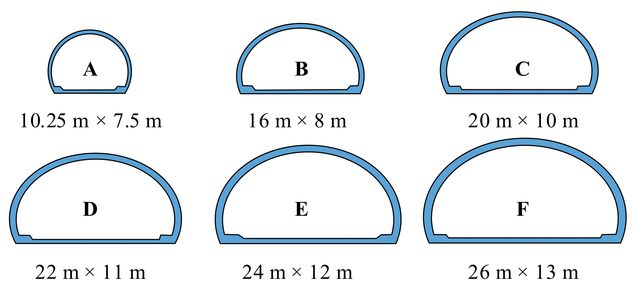
The increase in the tunnel cross-section does not only have negative impacts on the ventilation design. Sun et al. [131] selected six different cross-section sizes (as shown in Figure 17, where A represents a large cross-section and the others represent extra-large cross-sections) and established tunnel models, respectively. They found that as the cross-section size increases, the distance for the smoke to reach the tunnel ceiling during a fire becomes longer, and the maximum temperature of the ceiling structure is also reduced. In addition, Chi et al. [132] found that adopting a transverse ventilation scheme (constructing a rail-top air duct at the tunnel roof) can greatly reduce the reliance of large-cross-section tunnels on mechanical ventilation equipment. The common air duct layout methods are shown in Figure 18. The exhaust gas emitted by diesel locomotives in the tunnel has a certain amount of heat and will naturally rise. Placing the air duct at the tunnel roof can more effectively capture and discharge these rising harmful gases, enabling a good convection between the fresh air from the outside and the air inside the tunnel. This not only achieves the efficient discharge of exhaust gas but also reduces the reliance on large-scale ventilation equipment.
(2)
Cross-section shape
Common cross-section shapes of tunnels include circular, horseshoe-shaped, and rectangular. Circular and horseshoe-shaped cross-sections have uniform airflow distribution and low local resistance, making them suitable for long tunnels. Rectangular and straight-wall arched cross-sections are convenient for construction, but vortices are likely to occur at the corners, leading to an increase in local resistance. Currently, most single-track and double-track tunnels have horseshoe-shaped cross-sections, while multi-track tunnels mostly have rectangular or multi-circular mixed cross-sections. Peltier et al. [133] established tunnel models with circular, horseshoe-shaped, and cut-and-cover cross-sections to study the convective heat transfer phenomenon and the development of velocity and thermal boundary layers in the tunnel. The study found that the cross-section shape of the tunnel affects the development of the thermal boundary layer but not the development of the velocity boundary layer. The variation in the heat transfer coefficient along the longitudinal length of the circular cross-section is the most significant. It is recommended that circular/horseshoe-shaped cross-sections can also be preferentially selected for short tunnels to utilize the longer strong heat transfer area.
(3)
Tunnel length
Railway tunnels are generally classified into short tunnels (L < 500 m), medium-long tunnels (500 m ≤ L < 3000 m), long tunnels (3000 ≤ L < 10,000 m), and extra-long tunnels (L ≥ 10,000 m) according to their length. For short tunnels, ventilation can rely on the train piston wind and natural wind, but the pollutant concentration under the most unfavorable meteorological conditions needs to be checked. Medium-sized tunnels must adopt mechanical ventilation, such as jet fans. In long tunnels, CO, NOx, and heat emitted by diesel locomotives are likely to accumulate continuously in the tunnel. It is necessary to adopt segmented ventilation or design a combined ventilation system of “longitudinal + transverse” [134]. Considering that the construction terrain of diesel locomotive railway tunnels is usually high mountains and deep valleys, it is difficult to set up auxiliary tunnels, and the synchronous construction of shafts and inclined shafts is challenging. Sufficient attention should be paid to the ventilation problem of extra-long diesel locomotive railway tunnels.
(4)
Tunnel gradient
When the gradient of a diesel locomotive railway tunnel increases, the load on the diesel locomotive will increase correspondingly during the uphill operation. At this time, there will be a significant increase in the exhaust gas emission and temperature, and the required ventilation volume will also increase accordingly. During the downhill operation, although the exhaust gas emission of the diesel locomotive will be relatively reduced, the braking process of the train may cause an increase in the concentration of particulate pollutants in the tunnel. Kong et al. [135] established ventilation models of tunnels with different gradients using ANSYS Fluent software to study the flow field characteristics and ventilation effects of jet fans under different gradient conditions. It was found that as the tunnel gradient increases and the number of gradient changes increases, the average wind speed of the tunnel cross-section gradually decreases, and in the gradient-changing area, the pressure-boosting coefficient of the fans decreases significantly.

6.3. Operation Conditions of the Train

The influence of train operation on tunnel ventilation is mainly reflected in aspects such as the train piston effect, thermal effect, and airflow disturbances under different operation modes. Research shows that the piston wind generated by trains running in tunnels helps to expel harmful gases from the tunnel [136]. Gu et al. [137] conducted a systematic study on the influencing factors of the piston wind speed of running trains and found that the piston wind speed is positively correlated with the train speed and negatively correlated with the tunnel cross-sectional area. Xue [138] and Niu et al. [103] combined on-site measurements with numerical simulations to study the influence of piston wind on the airflow and found that there are specific diversion and suction ratios in each airflow passage.
The start/stop of trains, the opening and closing of air shafts, and the adjustment of the ventilation system all generate a large amount of heat, which exacerbates the temperature rise in the tunnel. Bifurcated tunnels can save railway lines and improve line utilization. However, the multiple entrances and exits of bifurcated tunnels induce air cross-flow, i.e., the mixing of fresh air and polluted air inside the tunnel. This makes it difficult to efficiently remove pollutants, prolongs the residence time of pollutants inside the tunnel, and makes diffusion more difficult [139]. The uphill and downhill operations of trains also have different impacts on ventilation. When a train is going uphill, the load on the diesel locomotive increases, and the exhaust gas and heat emissions increase significantly. When going downhill, the braking energy can be utilized, and the piston effect is enhanced [140].
The most unfavorable ventilation conditions in a tunnel are usually related to the interactive operation of multiple trains. When two trains meet in a tunnel, the velocity field of the fluid in the tunnel changes drastically, and multiple vortex regions may appear. At the same time, the running stability of the trains is also affected. Specifically, when two trains meet head-on, the directions of the piston winds are opposite, which leads to a decrease in the airflow velocity in the middle of the tunnel and forms an airflow stagnation zone, resulting in the accumulation of pollutants [141]. At this time, the effect of natural ventilation weakens, and it is necessary to increase the power of mechanical ventilation or set up intermediate air shafts and partitions. When two trains meet in the same direction, the pollutants from the leading train have not been completely removed when the following train enters the tunnel, resulting in the superposition of pollutant concentrations in the tunnel. If the speed difference between the two trains is large, the pollutants emitted by the leading train may not have sufficient ventilation time to be discharged outside the tunnel. As a result, the trailing train may experience insufficient oxygen concentration inside the tunnel, which can exacerbate incomplete fuel combustion. This may lead to the loss of traction power and potentially increase pollutant emissions. In this case, the requirements for ventilation inside the tunnel will be further elevated.
Therefore, the influence of train operation conditions on the ventilation system is mainly reflected in the impact of the piston wind effect on the diffusion of pollutant concentrations in the tunnel. The tunnel ventilation system needs to dynamically adjust its operating state according to the real-time position of trains and the passing intervals between different trains, such as delaying the shutdown of fans or increasing the ventilation wind speed. In practical engineering, the real-time position of trains can be accurately detected by sensors. However, affected by the train headway, the effective ventilation time available for reducing the pollutant concentration is often uncertain. Technologies such as big-data analysis can be adopted to achieve the orderly scheduling of trains and increase the effective ventilation time.

6.4. Ventilation Structures

In practice, vertical shafts and inclined shafts are usually installed to connect the enclosed tunnel space with the outside [142,143]. For parallel multi-tunnel systems, transverse passages are often set between different main tunnels. The installation of these ventilation structures significantly changes the airflow path, resistance, zoning capacity, and emergency smoke exhaust capacity inside the railway tunnel.
(1)
Influence of vertical shafts and inclined shafts
If a long tunnel only relies on the two end openings for longitudinal ventilation, it will face large wind resistance and insufficient air volume at the end, which often makes it difficult to discharge pollutants. Installing vertical shafts and inclined shafts is equivalent to opening multiple “skylights” or “side doors” in the middle or along the tunnel, dividing the long tunnel into several shorter ventilation sections, as shown in Figure 19. Fresh air only needs to be sent to the nearest air supply shaft, and exhaust gas only needs to be discharged from the nearest exhaust shaft, greatly shortening the ventilation path and time. The shortened ventilation path means less frictional resistance along the way, and the requirement and dependence on the fan power are also reduced accordingly. In addition, independent control of air volume and air velocity can be carried out for different zones to adapt to the changes in pollutant concentration in different sections. When utilizing the train piston wind effect, vertical shafts can serve as supplementary air inlets or pressure relief ports for the piston wind. Cong et al. [144] used the natural ventilation pressure analysis method and found that the natural ventilation pressure in a tunnel with vertical shafts is ten times that in a tunnel without vertical shafts. Li et al. [145] found that inclined shafts, horizontal passages, and vertical shafts help to relieve the peak transient pressure experienced by trains, thereby improving passenger comfort. Vertical/inclined shafts are also crucial smoke exhaust outlets and rescue escape passages in case of fire. Powerful smoke exhaust fans quickly extract high-temperature and toxic smoke out of the tunnel through the exhaust shafts to prevent the spread of smoke, creating a smokeless or low-smoke environment for personnel escape and fire-fighting rescue [26]. The layout of vertical/inclined shafts and transverse passages can also achieve smoke exhaust zoning. By shutting off the air supply in the zone near the fire source and increasing the smoke exhaust volume of the exhaust shafts, the spread range of smoke can be limited.
Some scholars have also made partial improvements to the design of traditional vertical shafts. For example, Fan et al. [146] studied the natural ventilation performance of shallow-buried urban tunnel vertical shafts under the action of the external wind field and proposed a ventilation method of installing jet fans downstream of the vertical shafts, and verified the effectiveness of the method through numerical simulation. Zhou et al. [103] conducted research on the optimization of the natural ventilation performance of urban tunnels. Based on an innovative method of solid smoke-blocking plates, they installed adjustable-angle solid smoke-blocking plates under the vertical shafts to form a chimney-effect enhancement structure. By conducting parametric studies on the height, angle of the baffle, and longitudinal air velocity, the smoke control time can be greatly shortened.
(2)
Influence of transverse passages
Transverse passages are key structures connecting the main tunnel with parallel service tunnels/pilot tunnels. In semi-transverse or full-transverse ventilation systems, fresh air can be evenly supplied to each cross-section of the main tunnel through dedicated air ducts (usually parallel to the roadway) or service tunnels and then through the transverse passages, achieving “complementary effect between two tunnels” [147] and optimized air exchange in the tunnel. In addition, polluted air can be collected into the exhaust ducts or service tunnels through the transverse passages and then discharged centrally. Based on this, a variety of new ventilation methods have been derived. For example, Chen [37] proposed a fire-prevention ventilation scheme for double-bore single-track tunnels. When a fire occurs, jet fans at both ends of the tunnel entrance pressurize the inside of the tunnel, and air is supplied from the safety tunnel to the accident tunnel. Rafael et al. [47] found based on the Inner Belt roadway “Ronda del Mig” in Barcelona that setting exhaust ports in the transverse internal passages between two independent parallel tunnels can effectively evacuate smoke in case of a fire. Zhou et al. [148] also found that the critical velocity in the transverse passage is related to the fire source location, semi-transverse smoke exhaust velocity, height of the protective door, and tunnel blockage ratio.
In summary, the installation of ventilation structures such as vertical shafts, inclined shafts, and transverse passages directly affects the direction, magnitude, and distribution of the airflow in the tunnel. A reasonable layout can not only help speed up tunnel construction [149] but also ensure that the entire tunnel receives a uniform and sufficient supply of fresh air and efficient discharge of polluted air, effectively improving the ventilation effect of the railway tunnel. However, the ventilation structures themselves will bring local resistance (such as bends and cross-section changes). For example, local resistance will be generated at the connection (confluence/diversion) between the vertical/inclined shaft and the main tunnel. Improper design will increase the system energy consumption. The angle of the inclined shaft affects the smoothness of the airflow and the construction difficulty. The size, length, number of elbows, and internal smoothness of the transverse passages will also directly affect the resistance loss when the airflow passes through. A too-small or roughly designed transverse passage will become a ventilation bottleneck.

6.5. Effect of Auxiliary Ventilation Equipment

Fans are common ventilation devices. The power (wind speed), installation position, deflection angle (wind direction), and working time of the equipment will have a great impact on the ventilation effect. Based on the theoretical introduction in Section 5, it can be known that according to the parameters such as the size of the tunnel, the air volume required to dilute the concentration of harmful gases to the designed concentration can be preliminarily estimated, and then the scale of the fans required can also be obtained.
(1) Fan wind speed. Generally speaking, in the same tunnel environment, the faster the fan wind speed, the more conducive it is to the rapid diffusion of polluted gases in the tunnel. In the fire scenario, Tuovinen et al. [150] used CFD simulation and found that as the ventilation speed increases, the spread speed of dangerous hot gases decreases. However, Piet Hartman et al. [151] considered the escape passages in the tunnel and found that when the wind speed of the tunnel jet fans is too fast, the resulting pressure increase will cause the pressure in the tunnel to be greater than that in the escape passages, leading to the escape passages being filled with smoke, which is not conducive to the safe evacuation of personnel. Barbato et al. [152] studied the critical ventilation speed and found that the tunnel geometry, slope, and type of heat release rate all have an impact on the critical ventilation speed.
(2) Fan position. Zhao et al. [25] studied the influence of the installation position of jet fans for disaster-prevention ventilation on the ventilation effect based on the network ventilation algorithm and three-dimensional numerical method. They found that since the protective door is located between the auxiliary tunnel and the main tunnel, the distance between the jet fan and the protective door will directly affect the ventilation efficiency. Yuan et al. [49] installed jet fans at two tunnel entrances. Based on the FDS simulation software and full-scale ventilation experiments, they found that the grouped induced ventilation design can effectively suppress the back-flow of smoke. Taking the length optimization of the air chamber parameters as an example, Tao et al. [153] used a three-dimensional numerical model verified by field tests to explore the influence of the air chamber length, partition length, and fan arrangement method on the ventilation efficiency of the axial fan. They found that the best arrangement method of the axial fan is to arrange it symmetrically along the axis, which can obtain the maximum airflow velocity and drainage range in the air chamber. This new ventilation system forms a relay ventilation by setting a sealed air chamber at the intersection of the main tunnel and the inclined shaft, greatly extending the ventilation distance and improving the ventilation efficiency.
(3) Fan deflection angle. The deflection of the fan also has a significant impact on the airflow in the tunnel. Tang et al. [154] used numerical simulation and found that when two ceiling-mounted fans are arranged with a deflection of 2–5°, the pressure lift of the fans can be increased, the jet resistance loss of the fans can be reduced, which is beneficial to the ventilation of the tunnel with over-development. Chen et al. [155] also found that tilting the fan outlet in the tunnel downward at a certain angle can reduce the wall shear stress and improve the pressure lift coefficient. Lee et al. [156] analyzed the ventilation characteristics of jet fans installed on a certain expressway under different elevation angle conditions at the inlet and outlet. They found that when the elevation angle of the fan is low, the energy loss caused by the friction of the tunnel roof is significant, and when the elevation angle is too high, the energy loss mainly comes from the airflow recirculation. When the elevation angle is 6.0°, the comprehensive energy loss of the roof and the floor is the smallest, and the ventilation effect is the best. Although this study is aimed at highway tunnels, the research conclusions still have reference value for the design of fans in railway tunnels. Li et al. [157] studied the single-heading excavation of double-bore tunnels. When the power of the forced-ventilation equipment in the two tunnels is different, CO will diffuse to the other tunnel along the crosswalk, causing air pollution in the adjacent tunnel. Therefore, during the blasting excavation of double-bore tunnels, the ventilation power should be kept the same to reduce the diffusion range of CO.
In summary, the selection of the fan wind speed and installation position in the tunnel should be combined with the specific conditions such as the tunnel geometry, length, slope, and the setting of ventilation structures. Deflecting the fan outlet at a certain angle can reduce the frictional resistance loss between the conveyed air and the tunnel sidewall. When multiple fans are installed, cooperation between different fans also needs to be considered.

6.6. External Environmental Condition

There are many external environmental factors that affect the ventilation of railway tunnels, such as natural wind direction and speed, temperature, humidity, and air pressure.
(1)
Altitude
The influence of altitude on ventilation is mainly reflected in the changes in air density and natural wind pressure. As the altitude increases, the atmospheric pressure decreases, and the air density decreases. According to the principles of fluid mechanics, the performance of the fans in the ventilation system is closely related to the air density. In high-altitude areas, due to the low air density, the actual air volume and pressure generated by the fans will be lower than those in low-altitude areas. For example, a fan with the same power will transport less air mass in a high-altitude tunnel, resulting in a reduction in ventilation capacity. Chen et al. [158], relying on the Mangkang Mountain Tunnel project of the Sichuan-Tibet Railway, found that the CO generated by tunnel blasting increases with the increase in altitude, and the dust flows along the wall, aggregates into clusters and diffuses towards the tunnel entrance. When the wind speed is too high, the decreasing trend of the dust mass concentration slows down.
The difference in altitude can also lead to the formation of natural wind pressure inside and outside the tunnel. In mountainous areas, with different altitudes at the tunnel entrance and exit, air will flow from high-altitude areas to low-altitude areas due to gravity. If the direction of this natural wind pressure is consistent with the design direction of the ventilation system, it will help enhance the ventilation effect and reduce ventilation energy consumption. Conversely, if the directions are opposite, it will increase the burden on the ventilation system and reduce the ventilation efficiency. Guang et al. [159], in order to determine the movement law of fire smoke in the shaft of a high-altitude tunnel under natural ventilation conditions, found through simulation studies that the critical Richardson number decreases under reduced-pressure conditions. The main reasons for the decrease in the critical Richardson number are the increase in smoke temperature and the acceleration of the flow velocity caused by the decrease in environmental pressure. Liu et al. [160] simulated the flow velocity and temperature distribution of fire smoke in high-altitude areas and found that the smoke flow velocity is proportional to the altitude, and due to heat loss, the smoke velocity decays exponentially along the longitudinal direction.
(2)
Temperature
An increase in temperature causes air to thermally expand and its density to decrease. In a tunnel, if the temperature inside the tunnel is higher than the outside temperature, the hot air will rise, forming a natural upward airflow. This natural convection phenomenon will affect the airflow organization of the ventilation system. When the temperature distribution inside the tunnel is uneven, the air density in different temperature regions varies, which will generate local airflow circulation and interfere with the normal operation of the ventilation system, reducing the ventilation effect. Temperature also affects the diffusion speed of pollutants in the tunnel. Generally, the higher the temperature, the faster the diffusion speed of pollutants.
(3)
Natural wind
Considering the natural wind speed is of positive significance for the design of the tunnel ventilation system [149]. When the natural wind speed is high and the direction is consistent with the tunnel ventilation direction, the natural wind will have a positive pressure effect on the tunnel ventilation [161]. At this time, the ventilation system can use the power of the natural wind to reduce the operating power of the fans and lower the ventilation energy consumption. If the natural wind speed is high but the direction is opposite to the tunnel ventilation direction, it will form a negative pressure, hindering the normal discharge of air inside the tunnel and reducing the ventilation effect. In this case, the ventilation system needs to overcome the resistance of the natural wind to achieve ventilation, increasing the load on the fans. When the natural wind speed is unstable or the wind direction is changeable, it will cause the airflow inside the tunnel to be disordered. The unstable airflow will disrupt the airflow organization of the ventilation system, making the ventilation effect uneven. It may even form eddies inside the tunnel, affecting the discharge of pollutants and the normal operation of the ventilation system. This is quite common in complex mountain tunnels where the wind direction and speed change frequently.
The complex and changeable environmental characteristics often pose great challenges to tunnel ventilation. With the continuous increase in deep-sea tunnels, high-altitude tunnels, and extra-long tunnels, the necessity of real-time monitoring of meteorological data is becoming increasingly prominent. Wang et al. [162] systematically monitored the longitudinal temperature, humidity, wind speed, and the concentrations of CO, NO2, and particulate matter in the Xiamen Xiang’an Subsea Tunnel (as shown in Figure 20) to study the longitudinal distribution laws of environmental parameters and motor vehicle pollutants in the urban subsea highway tunnel. The study found that the air temperature and relative humidity at the tunnel exit are relatively high, the NO2 concentration exceeds the threshold, and the V-shaped slope has a significant impact on the distribution of motor vehicle pollutants. The emissions of CO and NO2 on the uphill section are 2.78 times and 1.28 times those on the downhill section, respectively. In the longitudinal V-shaped slope of the subsea tunnel, particulate matter will coalesce with water droplets in the air, gradually aggregating into larger particles, which will accumulate at the slope bottom or adhere to the tunnel wall under the action of gravity, reducing the visibility at the slope bottom and affecting driving safety.
In addition to deep-sea tunnels, the environmental characteristics of high-altitude tunnels are also complex, featuring low air pressure and low density. Yao et al. [119] studied the flow law of smoke in high-altitude tunnels through numerical simulation and found that, under a certain fire source power, the thickness of the downstream smoke layer increases with the increase in environmental pressure and ventilation speed, and the influence of the ventilation speed is more obvious. Tian et al. [163], considering factors such as the temperature difference between the inside and outside of the tunnel and the wind speed, proposed a ventilation scheme of shaft supply and exhaust + complementary air duct diversion + jet fans for extra-long tunnels.

6.7. Diffusion Coefficient

The diffusion coefficient in a tunnel is an important parameter describing the diffusion ability of pollutants in the air within the tunnel. It reflects the characteristic of pollutants gradually dispersing in the tunnel due to molecular diffusion, turbulent diffusion, etc. It is usually denoted by the symbol D with the unit of m2/s. Sun et al. [164] monitored the concentrations of CO and NOx (converted to NO2) and the wind speed during the normal operation of the tunnel. Combining theoretical analysis and one-dimensional numerical simulation methods, they found that the diffusion coefficients of CO and NOx in high-altitude single-track railway tunnels with diesel locomotives are much larger than those in plain areas. Sun et al. [165,166] calculated and analyzed the diffusion coefficients of NOx and CO in Laoguanjiao Tunnel, Yangbajing No. 1 Tunnel, and Kuixian Tunnel, and found that:
(1) The diffusion coefficients of NOx and CO in the tunnel increase with the increase in wind speed, and the relationship conforms to the quadratic function D = au2 + bu + c is the wind speed in the tunnel, and a and c are fitting constants. By substituting the wind speed into the above function, the pollutant diffusion coefficients under different wind speed conditions can be estimated.
(2) Under mechanical ventilation conditions, the diffusion coefficients of NOx and CO are higher than those under natural ventilation conditions. Mechanical ventilation has an important influence on the spatial distribution of the diffusion coefficient.
(3) The pollutant diffusion coefficient in the tunnel is also related to the distance from the tunnel entrance. As can be seen from the above, the diffusion coefficient is a comprehensive representation of the diffusion characteristics of pollutants in the tunnel. The diffusion coefficients of different pollutants vary, and they are affected by multiple factors, so it is difficult to accurately estimate them. In practice, the determination of the diffusion coefficient often requires on-site tests and long-term monitoring.
In conclusion, the working efficiency of the railway tunnel ventilation system is closely related to the distribution of pollutant concentrations in the tunnel, the dimensional parameters of the tunnel, the ventilation structure, the ventilation equipment, and the operating conditions of the train. It also highly depends on external environmental conditions such as altitude, temperature, humidity, and natural wind. The comprehensive influence of external environmental conditions can be macroscopically reflected by the diffusion coefficient. Different influencing factors often jointly change the ventilation performance through complex coupling effects [167].
The preceding six subsections have individually enumerated various factors that may impact ventilation efficiency from different perspectives. However, in practice, these factors are closely interrelated and interact with each other. Consequently, the influence of individual factors on the overall ventilation effect is often difficult to isolate and analyze separately. For instance, as mentioned earlier, the diffusion coefficient is a critical factor affecting pollutant dispersion. Yet, the diffusion coefficient itself is influenced by multiple variables such as atmospheric pressure, altitude, and temperature, among which, altitude also affects temperature. The dynamic dispersion patterns of pollutants within the tunnel are collectively determined by the tunnel cross-sectional dimensions, the ventilation structures, and the operating conditions of the train. Furthermore, the optimal operating state of the ventilation system during operation is closely linked to both the current operating status of the train and the natural wind conditions. A single factor is seldom sufficient to determine the overall ventilation effect. How to achieve effective ventilation control by accounting for the interconnected influences of these factors constitutes a systematic research topic worthy of investigation.

7. Ventilation Control for Diesel Locomotives Railway Tunnels

The ventilation control technology for diesel locomotive railway tunnels is a crucial part in ensuring the air quality inside the tunnel and the safety of train operation. Its core control strategies can be divided into three major categories: passive control, active control, and intelligent control. The selection of the ventilation system mainly depends on tunnel parameters such as length, traffic direction, and traffic volume [168].

7.1. Traditional Ventilation Control Modes

The traditional control mode for tunnel ventilation is to ventilate the tunnel with a fixed time and volume after a train passes. Based on experience or statistical data, the operation time and mode of ventilation equipment (such as fans) are preset in advance, which is generally achieved by fans [126]. Regardless of the actual traffic flow and pollutant concentration changes in the tunnel, the ventilation system operates according to a fixed schedule. This control mode is simple, easy to implement, and low-cost. However, it lacks flexibility and may lead to energy waste or insufficient ventilation [169]. For example, during periods of low traffic flow, the ventilation system operating according to a fixed schedule may provide excessive ventilation and consume unnecessary electrical energy.
Traditional ventilation control modes also include natural ventilation and manual control. Natural ventilation is generally suitable for short tunnels [170] and will not be introduced in this paper. Manual control means that operators can manually turn on, turn off, or adjust the operating power of ventilation equipment based on intuitive feelings such as the smell and visibility in the tunnel, or based on experience and some simple monitoring data. Especially when a major accident occurs in the tunnel, manual control can quickly turn on all the fans in the tunnel to avoid secondary hazards. Although manual control has a certain degree of flexibility, it depends on the experience and judgment of operators, is highly subjective, and is prone to misoperation. Moreover, it cannot respond promptly to the rapid changes in the tunnel environment. For example, when a sudden traffic accident in the tunnel causes a sharp increase in pollutant concentration, manual control may not be able to make an effective response in time.

7.2. Sensor-Based Active Control

The active control of tunnel ventilation refers to a ventilation mode that determines the operating state of ventilation equipment based on the detection results of (pollutant and vehicle) sensors.
(1) Concentration sensing: Multiple pollutant concentration sensors are installed in the tunnel to monitor the pollutant concentration in the tunnel in real-time. When the pollutant concentration exceeds the set threshold, the ventilation control system automatically adjusts the operating parameters of the ventilation equipment to increase the ventilation volume and reduce the pollutant concentration; when the pollutant concentration is below the threshold, the ventilation volume is appropriately reduced to save energy. This method can adjust the ventilation volume in real-time according to the actual pollutant concentration in the tunnel, achieving precise control, improving ventilation efficiency, and reducing energy consumption. However, the accuracy and reliability of sensors have a significant impact on the control effect. Sensors need to be regularly maintained and calibrated to ensure the accuracy of monitoring data.
(2) Traffic sensing: The traffic operation state in the tunnel is also an important reference for determining the optimal ventilation scheme. In an active control system, traffic sensors such as loop detectors and video detectors installed in the tunnel are generally used to monitor the traffic flow and vehicle speed in the tunnel in real-time. The pollutant generation in the tunnel is predicted according to the changes in traffic flow and vehicle speed, and the operating state of ventilation equipment is adjusted accordingly. Generally, the greater the traffic flow and the slower the vehicle speed, the more pollutants are generated, and the ventilation volume needs to be increased accordingly. This method can dynamically adjust the ventilation volume according to the changes in traffic flow, improving the adaptability of the ventilation system. However, the relationship between traffic flow and pollutant generation is relatively complex and is affected by various factors such as vehicle type and vehicle operating state.

7.3. Intelligent Control

As previously mentioned, numerous factors influence the ventilation conditions inside tunnels, including air velocity, air circulation within the tunnel, wind speed, train operating conditions, and train pollutant emissions. These factors typically exhibit dynamic changes. To comprehensively account for the impact of the above factors and adapt to their dynamic variations, intelligent control is required to regulate the operation of jet fans [171]. In current research on tunnel fire ventilation control, there are many research methods involving intelligent control. Common ones include fuzzy control [171,172], PID control (Proportional–integral–derivative, PID) [173], and neural network control [174,175].
(1) Fuzzy Control: Fuzzy control is an intelligent control method based on fuzzy logic. It does not require the establishment of an accurate mathematical model. Instead, based on the experience of operators and expert knowledge, it performs fuzzy processing on the environmental parameters inside the tunnel (such as pollutant concentration, traffic flow, wind speed, etc.) and the operating states of ventilation equipment. Then, it determines the control strategy for the ventilation equipment through fuzzy inference rules. This control strategy has strong robustness and adaptability, can handle complex nonlinear systems, and can quickly respond to changes in the tunnel environment. However, the formulation of fuzzy rules requires a large amount of experience and professional knowledge, and the effectiveness of fuzzy control depends to a certain extent on the rationality of the fuzzy rules. Chen et al. [176] combined fuzzy control to conduct numerical simulations of the tunnel ventilation conditions under different train operating conditions, respectively. They found that the simulation of the fuzzy control system can effectively adjust the pollutant concentration. However, this method also has a certain degree of randomness and relies on experts to construct fuzzy control rules, so it cannot achieve autonomous online learning. When factors such as tunnel pollutants and traffic volume change, the prediction results of the control system will have errors. Xia et al. [177] developed a model calculation program and established a complementary ventilation operation mode. They switched different ventilation modes according to different traffic volumes of highway tunnels, which is more flexible and practical, reducing the energy consumption of the ventilation system and the operating costs. Li et al. [171] introduced the combined gray system theory and fuzzy control (Combined gray prediction fuzzy control law) in their research. Aiming at the highly linear and uncertain characteristics of the highway tunnel ventilation system, they proposed a prediction system response framework suitable for highway tunnel ventilation. Through simulation and experimental research, they found that the performance of the gray prediction fuzzy control is better, and the energy consumption is lower than that of the traditional tunnel ventilation control methods. Yang et al. [178] applied fuzzy identification to the longitudinal ventilation control of highway tunnels. They combined the principles of fuzzy C-means clustering and recursive least-squares method to predict the pollutant concentration inside the tunnel and reasonably controlled the number of fans to be turned on based on the pollutant concentration.
(2) PID Control: In the field of tunnel ventilation control, PID control is a commonly used and effective technical means. The PID controller calculates the control quantity through the linear combination of three links: proportional (P), integral (I), and derivative (D) based on the error between the set value (desired output) and the actual output value of the system, so as to adjust the system output to make it as close as possible to the set value. The principle and structure of the PID controller are relatively simple, easy to understand and implement, do not require complex modeling of the system, and have strong robustness. It is widely used in industrial control, process control and other fields, and the technology is mature. However, the parameter tuning of this control method is difficult. Appropriate values need to be tuned according to the specific system and operating conditions. For complex systems, the parameter tuning process may be cumbersome, and it is difficult to achieve the optimal effect. Moreover, it has poor adaptability to nonlinear systems. Si et al. [179] proposed a ventilation operation control strategy based on ADRC to solve the problems of overshoot and hysteresis in the PID control system, which improved the working efficiency of the ventilation system. Hong et al. [178] combined the CFD model and the PID control algorithm to automatically adjust the longitudinal ventilation speed according to the deviation between the control point temperature and the set temperature. They used the genetic algorithm and dimensional analysis method to obtain optimal PID control parameters.
(3) Neural Network Control: Neural network control utilizes the learning and adaptive capabilities of artificial neural networks to control the tunnel ventilation system. Through learning a large amount of historical data, the neural network can establish a complex mapping relationship between the environmental parameters inside the tunnel and the operating states of the ventilation equipment. Therefore, in actual operation, the neural network can automatically adjust the operating parameters of the ventilation equipment according to the real-time monitored environmental parameters to achieve the optimal ventilation effect. However, the training process of the neural network is complex, requiring a large amount of historical data and computing resources. Moreover, the design of the network structure and the adjustment of parameters require professional knowledge and experience. Feng et al. [99] used a high-geothermal tunnel ventilation environment temperature prediction method that combines a convolutional neural network (CNN) and a bidirectional long-short-term memory network (BiLSTM) to predict the future ventilation environment temperature inside the tunnel. Sun [169] combined the unsteady flow theory and the neural network model to propose a tunnel ventilation control method based on full-automatic control, which achieved the effect of energy conservation and was quite practical. Li et al. [174] trained based on the radial basis function (RBF) neural network algorithm model, calculated and analyzed different fire scales and occurrence positions under random operating conditions, and conducted an actual-case prediction for the project. The results showed that the intelligent control model has a positive significance for improving the safety of highway tunnels during the operation period. Luo et al. [146] applied intelligent control technology to the field of tunnel construction ventilation. They combined the augmented ZNPID algorithm to normalize the excessive pollutant concentration and found that the above-mentioned intelligent ventilation system can significantly reduce power consumption compared with traditional methods. Liu et al. [180] proposed an intelligent frequency control system for tunnel ventilation based on the radial basis function neural network and established the relationship between the operating efficiency of tunnel fans and the tunnel environment. This system can automatically adjust the frequency of the fans according to the construction environment inside the tunnel, effectively improving the tunnel environment and enhancing the energy-saving effect. Wu et al. [181,182] established a large-scale tunnel fire database, conducted numerical simulations under different fire positions, scales, and ventilation conditions, and used artificial intelligence and deep learning to identify the fire source, so as to predict the temperature field and the changes in tunnel fires. Zhang et al. [183] constructed a digital twin system based on AIoT for the fire safety management of intelligent tunnels. They used an AI model trained by the Transformer network to monitor and control real-time tunnel fire scenarios, proving the feasibility of using a 3D environment and digital twin in real-time fire safety management. Ma et al. [120] proposed a tunnel ventilation and heat exchange prediction framework based on physics-informed machine learning, which accurately predicts the air humidity and temperature at the tunnel exit by combining past real-time data and future input information, providing a basis for efficient heat exchange in the tunnel. Li et al. [184] studied the fire ventilation control of highway tunnels. They coupled the linear active disturbance rejection control (LADRC) algorithm with three-dimensional CFD numerical simulation calculations. By establishing a simulation model to control the longitudinal ventilation speed and the back-flow length of fire smoke, they found that the LADRC ventilation control system has a better linear control effect on the back-flow of smoke for fires of different scales and is more stable than the PID control system.
Currently, tunnel ventilation control technology has advanced from traditional timing and manual control to intelligent control. Sensor-based control technology is widely used, which can adjust the ventilation in real-time according to pollutant concentration and traffic flow, improving accuracy and efficiency. PID control is also commonly used due to its simple structure and strong robustness. However, the existing technologies still have deficiencies under complex operating conditions, such as difficult parameter tuning, poor adaptability to nonlinear systems, and some technologies relying on high-precision sensors with high maintenance costs.
In the future, the main trends are intelligence and integration. Intelligent algorithms (such as fuzzy control and neural network control) and Big Data analysis technology will be deeply integrated to achieve more precise and intelligent ventilation control. At the same time, the integration of multiple systems will be strengthened, comprehensively considering factors such as traffic and the environment. In addition, energy conservation and environmental protection will be emphasized, and low-energy-consumption ventilation equipment and control strategies will be developed to meet the requirements of green development.

8. Conclusions

This review provides a comprehensive analysis of research related to ventilation technologies in diesel locomotive railway tunnels. It covers the development of diesel traction locomotives, the composition of ventilation systems, ventilation standards for pollutants within tunnels, commonly used research methods, key factors influencing ventilation effectiveness, and technologies employed for ventilation control. The main conclusions are as follows:
  • Diesel locomotives are the preferred form of railway freight train traction in developing countries with weak power infrastructure, as well as in high-altitude areas and permafrost regions. With the continuous development of these areas and the progress of the construction technology for ultra-long, ultra-wide and deeply buried railway tunnels, researching the ventilation issues of diesel locomotive railway tunnels is of great value for ensuring the safe operation and emergency rescue of railways in developing countries, high-altitude areas and permafrost regions.
  • Currently, the consideration and control requirements for pollutants in tunnels in the regulations of various countries are becoming more comprehensive. In particular, special attention should be paid to three pollutants: CO, NO and NO2. EU countries, represented by the UK and France, have significantly higher control requirements for pollutant concentrations in tunnels than other countries. In contrast, the regulatory standards of countries such as the US and Canada are more lenient. The determination of pollutant concentration limits in tunnels in a region should take into account the tunnel length, the altitude of the tunnel location and the population density, as well as the economic development status.
  • Combining multiple research methods, such as theoretical analysis, scale models, field tests, and numerical simulations, has become a new research approach. Experience and theories provide the basic direction and framework for conducting tests and simulations. Field tests can determine as realistic boundary parameters as possible for simulation analysis, while simulation analysis can reduce the trial-and-error cost of field tests. Finally, the research results obtained based on systematic simulation analysis and experimental verification can provide a basis for the further improvement of ventilation theories.
  • The working efficiency of railway tunnel ventilation systems is related to the specific concentration distribution of pollutants in the tunnel, the size parameters, ventilation structure and ventilation equipment of the tunnel, as well as the operating conditions of trains. Different influencing factors often jointly change the ventilation performance through complex coupling effects. The comprehensive influence of external environmental conditions such as altitude, temperature and humidity, and natural wind can be macro-embodied by the diffusion coefficient. The accurate determination of the diffusion coefficient requires long-term on-site monitoring.
  • Currently, tunnel ventilation control technology has advanced from traditional timing and manual control to intelligent control. The control technology based on sensors and PID has been widely used but still has limitations. In the future, the main trends are intelligence and integration. Intelligent algorithms such as fuzzy control and neural network control will be deeply integrated to assist in obtaining more accurate and effective monitoring data, help determine more reasonable ventilation schemes and contribute to achieving more precise and intelligent ventilation control. At the same time, multi-system integration will be strengthened, considering factors such as traffic and the environment, and greater emphasis will be placed on energy conservation and environmental protection to meet the future development needs of green and low-carbon.
  • Critical research gaps persist in achieving intelligent and green-low-carbon tunnel ventilation. A “safety–efficiency–resilience” coordinated control framework remains underdeveloped. Current studies predominantly focus on single-objective optimization of safety or energy efficiency, lacking integrated theoretical frameworks and resilient design methodologies capable of maintaining system safety and energy performance under disturbances such as equipment failures, traffic congestion, or extreme fire scenarios.
  • For emission control in diesel locomotive railway tunnels, it is imperative to establish dynamic carbon emission assessment and optimization models covering the entire lifecycle from construction and operation to decommissioning. Such models would enable accurate quantification of the carbon footprint associated with various ventilation strategies, thereby supporting evidence-based low-carbon design decisions.
  • A fundamental challenge in engineering applications of multi-physics real-time simulation and digital twin technology lies in balancing fluid dynamics model accuracy with computational efficiency, particularly in ultra-long tunnel scenarios. Achieving second-level prediction and proactive control of pollutant dispersion and ventilation response remains a critical unsolved problem.

Author Contributions

Conceptualization, X.C., S.S. and T.L.; data curation, X.C., T.L., L.L., X.S. and J.Y.; writing—original draft preparation, X.C. and T.L.; writing—review and editing, S.S. and J.W.; visualization, X.C., J.W., T.L. and J.Y.; supervision, S.S. and J.W.; project administration, S.S.; funding acquisition, X.C. and S.S. All authors have read and agreed to the published version of the manuscript.

Funding

This research was funded by the Science and Technology Project of China Railway Construction Corporation Limited, grant number 2021-B07.

Institutional Review Board Statement

Not applicable.

Informed Consent Statement

Not applicable.

Data Availability Statement

No new data were created.

Conflicts of Interest

The authors declare no conflicts of interest.

References

  1. RailSlider. The Role of Rail Transport in Intermodal Freight Transport. Available online: https://www.railsider.com/en/the-role-of-rail-transport-in-intermodal-freight-transport (accessed on 10 July 2025).
  2. Transportation Infrastructure and Equipment. In Logistics Transportation Systems; Elsevier: Amsterdam, The Netherlands, 2020; pp. 59–88. ISBN 9780128159743.
  3. World Rail Market Study 2024. Available online: https://www.dvvmedia-shop.de/en/World-Rail-Market-Study-2024/978-3-96892-235-5 (accessed on 10 July 2025).
  4. Vocational Training at VTG. Four Good Reasons to Transport Goods by Rail. Available online: https://www.vtg.com/news-and-insights/stories/four-good-reasons-to-transport-goods-by-rail (accessed on 28 October 2025).
  5. ZhiYan Consulting. 2025–2031 China Coal Transportation Industry Market Research and Future Trend Forecast Report; Report Number R977775; ZhiYan Consulting: Beijing, China, 2025. (In Chinese) [Google Scholar]
  6. Barbosa, F.C. Fuel Cell Rail Technology Review: A Tool for an Autonomous Rail Electrifying Strategy. In Proceedings of the 2019 Joint Rail Conference, Snowbird, UT, USA, 9–12 April 2019. [Google Scholar] [CrossRef]
  7. Ablyalimov, O.; Avdeyeva, A. Operation of Locomotives of Diesel Traction on Hilly Section of Railway. E3S Web Conf. 2023, 401, 01058. [Google Scholar] [CrossRef]
  8. Gotthard Base Tunnel | Definition, Switzerland, Opening, & Facts | Britannica. Available online: https://www.britannica.com/topic/Gotthard-Base-Tunnel (accessed on 10 July 2025).
  9. Rennie, R.P.; Jegier, Z.; Katz, M. Effect of diesel locomotive operation on atmospheric conditions in a railway tunnel. Can. J. Chem. Eng. 1960, 38, 123–128. [Google Scholar] [CrossRef]
  10. Sun, J.Y.; Fang, Z.; Chen, J.J. Full-Scale Experiment of Longitudinal Ventilation Smoke Control System and Central Smoke Exhaust System in City Underwater Tunnel. Procedia Eng. 2013, 52, 330–335. [Google Scholar] [CrossRef]
  11. Fruhwirt, D.; Sturm, P.; Steiner, H.; Borchiellini, R. Development of a methodology for studying tunnel climate in long railway tunnels and for optimizing the design process of cross-passage cooling systems. Tunn. Undergr. Space Technol. 2023, 138, 105194. [Google Scholar] [CrossRef]
  12. Ali, N.; Qi, Z. Defensible citadel: History and architectural character of the Lahore Railway Station. Front. Archit. Res. 2020, 9, 805–819. [Google Scholar] [CrossRef]
  13. Gong, J.F.; Wang, W.; Li, X.; He, W.; Yuan, Y. Statistics of China′s railway tunnels by the end of 2024 and overview of tun-nels of new projectsin 2024. Tunn. Constr. 2025, 45, 636–653. (In Chinese) [Google Scholar]
  14. History of U.S. Diesel-Electric AC Traction-Railway Age. Available online: https://www.railwayage.com/mechanical/locomotives/a-history-of-ac-traction/ (accessed on 10 July 2025).
  15. Vickers, R.L. The Beginnings of Diesel Electric Traction. Trans. Newcom. Soc. 1999, 71, 115–127. [Google Scholar] [CrossRef]
  16. Sutton, G.P. History of Liquid-Propellant Rocket Engines in Russia, Formerly the Soviet Union. J. Propuls. Power 2003, 19, 1008–1037. [Google Scholar] [CrossRef]
  17. Rao, N.U. The general motors GF6C electric locomotive. IEEE Trans. Ind. Appl. 1986, I, 502–511. [Google Scholar] [CrossRef]
  18. Allen, J.G.; Newmark, G.L. The Life and Death of North American Rail Freight Electrification. Transp. Res. Rec. 2018, 2672, 166–175. [Google Scholar] [CrossRef]
  19. Han, C.Y. 50 years of development of railway diesel locomotives in China. Railw. Locomot. Mot. Car 2008, 9, 1–7+17+51. (In Chinese) [Google Scholar]
  20. Development and Reform Department of China National Railway Group Co., Ltd. 2024 Statistical Bulletin; China National Railway Group Co., Ltd.: Beijing, China, 2025. (In Chinese) [Google Scholar]
  21. Urbański, P.; Huang, Y.; Gallas, D.; Zhou, J.L.; Merkisz, J. Real-world assessment of the energy consumption and emissions performance of a novel diesel-electric dual-drive locomotive. Sustain. Energy Technol. Assess. 2024, 71, 104017. [Google Scholar] [CrossRef]
  22. Al-Tony, F.E.S.; Lashine, A. Cost-benefit analysis of railway electrification: Case study for Cairo-Alexandria railway line. Impact Assess. Proj. Apprais. 2000, 18, 323–333. [Google Scholar] [CrossRef]
  23. Xu, L.; Huang, M.; Niu, J. Numerical study of indoor flow field and ventilation performance of the power room of a diesel locomotive under crosswind. J. Wind Eng. Ind. Aerodyn. 2023, 241, 105545. [Google Scholar] [CrossRef]
  24. Dedík, M.; Gašparík, J.; Záhumenská, Z.; Ľupták, V.; Hřebíček, Z. Proposal of the measures to increase the competitiveness of rail freight transport in the EU. Nase More 2018, 65, 202–207. [Google Scholar] [CrossRef]
  25. Zhao, D.P.; Wen, S.X.; Yang, B.H. Influence of Installation Position of Jet Fan on Ventilation Effect in Disaster Prevention Ventilation of Railway Tunnel. China Railw. Sci. 2021, 42, 59–70. (In Chinese) [Google Scholar]
  26. Yao, Y.; Wang, R.; Xia, Z.; Ren, F.; Zhao, J. Numerical study of the characteristics of smoke spread in tunnel fires during construction and method for improvement of smoke control. Case Stud. Therm. Eng. 2022, 34, 102043. [Google Scholar] [CrossRef]
  27. Han, N.; Hou, K.; Xu, J.; Liu, X.; He, M.; Li, N. Numerical study on ventilation cooling in a high geothermal tunnel of the Sichuan-Tibet Railway considering the tunnel drilling process. Int. J. Heat Fluid Flow 2024, 109, 109504. [Google Scholar] [CrossRef]
  28. Zhou, P.; Feng, Y.; Zhou, F.; Wei, Z.; Gou, S.; Xu, H.; Wang, Z. Evaluation system of worker comfort for high geothermal tunnel during construction: A case study on the highway tunnel with the highest temperature in China. Tunn. Undergr. Space Technol. Inc. Trenchless Technol. Res. 2023, 135, 105028. [Google Scholar] [CrossRef]
  29. Kagawa, J. Health effects of diesel exhaust emissions * a mixture of air pollutants of worldwide concern. Toxicology 2002, 181, 349–353. [Google Scholar] [CrossRef]
  30. Mainiero, R.J.; Harris, M.L.; Rowland, J.H. Dangers of Toxic Fumes from Blasting. Proc. Annu. Conf. Explos. Blasting Tech. 2007, 33, 73. [Google Scholar]
  31. Park, D.; Yoon, Y.; Kwon, S.B.; Jeong, W.; Cho, Y.; Lee, K. The effects of operating conditions on particulate matter exhaust from diesel locomotive engines. Sci. Total Environ. 2012, 419, 76–80. [Google Scholar] [CrossRef] [PubMed]
  32. Sturm, P.; Fruhwirt, D.; Steiner, H. Impact of dust loads in long railway tunnels: In-situ measurements and consequences for tunnel facilities and operation. Tunn. Undergr. Space Technol. 2022, 122, 104328. [Google Scholar] [CrossRef]
  33. Yuan, W.; Ji, W.; Zhang, J.; Du, T.; Yuan, Y. Examining smoke control in fires occurring in railroad tunnels: A review. J. Therm. Anal. Calorim. 2024, 149, 13–39. [Google Scholar] [CrossRef]
  34. Silverman, D.T.; Samanic, C.M.; Lubin, J.H.; Blair, A.E.; Stewart, P.A.; Vermeulen, R.; Coble, J.B.; Rothman, N.; Schleiff, P.L.; Travis, W.D.; et al. The diesel exhaust in miners study: A nested case-control study of lung cancer and diesel exhaust. J. Natl. Cancer Inst. 2012, 104, 855–868. [Google Scholar] [CrossRef]
  35. Janssen, N.A.H.; Hoek, G.; Simic-Lawson, M.; Fischer, P.; van Bree, L.; Brink, H.T.; Keuken, M.; Atkinson, R.W.; Ross Anderson, H.; Brunekreef, B.; et al. Black carbon as an additional indicator of the adverse health effects of airborne particles compared with pm10 and pm2.5. Environ. Health Perspect. 2011, 119, 1691–1699. [Google Scholar] [CrossRef]
  36. Tsukue, N.; Okumura, H.; Ito, T.; Sugiyama, G.; Nakajima, T. Toxicological evaluation of diesel emissions on A549 cells. Toxicol. Vitr. 2010, 24, 363–369. [Google Scholar] [CrossRef]
  37. Chen, S.H. Research on the Evacuation and Rescue Technology for Disaster Prevention of High Altitude Extra-long Tunnel. J. Railw. Eng. Soc. 2016, 33, 76–81. (In Chinese) [Google Scholar]
  38. Chen, X.; Sun, S.; Wu, J.; Ling, T.; Li, L.; Shi, X.; Yang, H. Ventilation Design of an Extra-Long Single-Bore Double-Track Railway Tunnel with High Traffic Density. Sensors 2025, 25, 4009. [Google Scholar] [CrossRef]
  39. Kruger. Available online: https://www.krugerfan.com/media/view/1/?lang=en (accessed on 13 July 2025).
  40. Williams, E.E.; Didandeh, H.; Cahill, K.M. Design of an innovative high-efficiency fan for engine cooling. In Proceedings of the Institution of Mechanical Engineers—VTMS 10, Vehicle Thermal Management Systems Conference and Exhibition; Woodhead Publishing: Cambridge, UK, 2011; pp. 435–445. [Google Scholar]
  41. Xiaoming, W.; Yu, Z.; Guang, Y.; Xinyu, Z.; Dong, L.; Hongliang, W.; Shiqiang, C.; Huan, D. Research on the ventilation and control method of double-hole complementary construction of long tunnel. Sci. Rep. 2025, 15, 5589. [Google Scholar] [CrossRef]
  42. Wang, R.; Fang, Z.; Wang, D.; Zhu, Z.; Li, H.; Wu, P.; Xu, Q.; Han, Y. Theoretical solution research on air curtain thermal insulation technology at tunnel portal in cold area. Sci. Rep. 2025, 15, 8780. [Google Scholar] [CrossRef]
  43. Vehicles Found Fused Together in Molten Mass after Tunnel Inferno | World News | The Guardian. Available online: https://www.theguardian.com/world/2001/oct/26/jonhenley1 (accessed on 10 July 2025).
  44. Ingason, H.; Lönnermark, A.; Li, Y.Z. Model of ventilation flows during large tunnel fires. Tunn. Undergr. Space Technol. Inc. Trenchless Technol. Res. 2012, 30, 64–73. [Google Scholar] [CrossRef]
  45. Zeng, Y.; Liu, K.; Fang, Y.; Zhang, X.; Bai, Y. Fire Model Test on Temperature Field in the Rescue Station of an Extralong Railway Tunnel. Adv. Civ. Eng. 2019, 2019, 1732572. [Google Scholar] [CrossRef]
  46. Tang, F.; He, Q.; Mei, F.; Wang, Q.; Zhang, H. Effect of ceiling centralized mechanical smoke exhaust on the critical velocity that inhibits the reverse flow of thermal plume in a longitudinal ventilated tunnel. Tunn. Undergr. Space Technol. 2018, 82, 191–198. [Google Scholar] [CrossRef]
  47. Ballesteros-tajadura, R.; Santolaria-morros, C.; Blanco-marigorta, E. Influence of the slope in the ventilation semi-transversal system of an urban tunnel. Tunn. Undergr. Space Technol. 2006, 21, 21–28. [Google Scholar] [CrossRef]
  48. Dastan, A.; Rahiminejad, M.; Sabz, M.; Abbasi, M. CFD simulations of a semi-transverse ventilation system in a long tunnel. Undergr. Space 2023, 11, 153–170. [Google Scholar] [CrossRef]
  49. Yuan, S.; Sun, X.; Liu, S.; Li, Y.; Du, P. Effectiveness of cluster-based inductive ventilation system in railway tunnels: Case study using full-scale experiment and fire dynamic simulation. Case Stud. Therm. Eng. 2022, 34, 102045. [Google Scholar] [CrossRef]
  50. Hajra, B.; Stathopoulos, T.; Bahloul, A. A wind tunnel study of the effects of adjacent buildings on near- fi eld pollutant dispersion from rooftop emissions in an urban environment. J. Wind Eng. 2013, 119, 133–145. [Google Scholar] [CrossRef]
  51. Wang, J.; Yuan, J.; Fang, Z.; Tang, Z.; Qian, P.; Ye, J. A model for predicting smoke back-layering length in tunnel fires with the combination of longitudinal ventilation and point extraction ventilation in the roof. Tunn. Undergr. Space Technol. 2018, 80, 16–25. [Google Scholar] [CrossRef]
  52. TB 10068-2024; Code for Design on Operation Ventilation of Railway Tunnel. National Railway Administration of the People’s Republic of China: Beijing, China, 2024.
  53. TB/T 1912-2005; Allowable Concentration and Measurement of Locomotive Exhaust in Railway Operating Tunnel. Ministry of Railways of the People’s Republic of China: Beijing, China, 2005.
  54. JTG/T D70/2-02-2014; Guidelines for Design of Ventilation of Highway Tunnels. Ministry of Transport of the People’s Republic of China: Beijing, China, 2014.
  55. TB 10068-2010; Code for Design on Operating Ventilation of Railway Tunnel. Ministry of Railways of the People’s Republic of China: Beijing, China, 2010.
  56. GBZ 2.1-2019; Occupational Exposure Limits for Hazardous Agents in the Workplace—Part 1: Chemical Hazardous Agents. National Health Commission of the People’s Republic of China: Beijing, China, 2019.
  57. Ministry of Emergency Management of the People’s Republic of China. Coal Mine Safety Regulations (Amended by: 2022); Ministry of Emergency Management of the People’s Republic of China: Beijing, China, 2022.
  58. Occupational Safety and Health Administration. Permissible Exposure Limits: OSHA Annotated Table Z-1; Occupational Safety and Health Administration: Washington, DC, USA, 2018.
  59. California Division of Occupational Safety and Health (Cal/OSHA). Permissible Exposure Limits For Chemical Contaminants (Table AC-1, Last Reviewed: 2025); California Division of Occupational Safety and Health: Bakersfield, CA, USA, 2025.
  60. National Institute for Occupational Safety and Health (NIOSH). NIOSH Pocket Guide to Chemical Hazards (Last Reviewed: 2020); National Institute for Occupational Safety and Health: Washington, DC, USA, 2020.
  61. American Conference of Governmental Industrial Hygienists (ACGIH). Threshold Limit Values for Chemical Substances and Physical Agents; American Conference of Governmental Industrial Hygienists: Cincinnati, OH, USA, 2024; ISBN 9781607261667. [Google Scholar]
  62. Federal Institute for Occupational Safety and Health of Germany (AGS). Occupational Exposure Limits. (TRGS 900, Amended by: 2024); Federal Institute for Occupational Safety and Health of Germany: Dortmund, Germany, 2024.
  63. German Research Foundation. Permanent Senate Commission for the Investigation of Health Hazards of Chemical Compounds in the Work Area; (MAK Commission). In List of MAK and BAT Values; German Research Foundation: Bonn, Germany, 2024. [Google Scholar]
  64. The Commission Of The European Communities. Establishing a Third List of Indicative Occupational Exposure Limit Values; The Commission Of The European Communities: Brussels, Belgium, 2017.
  65. The Council Of The European Union. Protection of Workers from Risks Related to Chemical Agents at Work (Council Directive 98/24/EC, Amended by: 2024); The Council Of The European Union: Brussels, Belgium, 2024.
  66. Miles, J. WHO Global Air Quality Guidelines: Particulate Matter (PM2.5 PM10), Ozone, Nitrogen Dioxide, Sulfur Dioxide Carbon Monoxide; WHO: Geneva, Switzerland, 2021; 290p. [Google Scholar]
  67. European Commission. COMMISSION REGULATION (EU) No 1303/2014 of 18 November 2014 concerning the technical specification for interoperability relating to ‘safety in railway tunnels’ of the rail system of the European Union. Off. J. Eur. Union 2014, 57, 394–420. [Google Scholar]
  68. National Fire Protection Association. NFPA 130 Standard for Fixed Guideway Transit and Passenger Rail Systems; National Fire Protection Association: Quincy, MA, USA, 2025.
  69. Group, M.; Blvd, M. Carbon Monoxide Concentration, Visibility and Smoke Simulation Underground Railway Stations in Case of Emergency. In Proceedings of the 20th International Transport and Air Pollution Conference 2014, Graz, Austria, 18–19 September 2014; pp. 1–14. [Google Scholar]
  70. Union International des Chemin Fer (UIC) UIC-Codex 779–9-Safety in Railway Tunnels. 2003. Available online: https://uic.org/com (accessed on 10 July 2025).
  71. Workplace safety and health of Singapore. Workplace Safety and Health (General Provisions) Regulations; Attorney-General’s Chambers of Singapore: Singapore City, Singapore, 2025. [Google Scholar]
  72. Safe Work Australia. Workplace Exposure Standards for Airborne Contaminants 2024; Safe Work Australia: Canberra, Australia, 2024. [Google Scholar]
  73. Japan Society for Occupational Health(JSOH). Occupational Exposure Limits; The Japan Society for Occupational Health (JSOH): Tokyo, Japan, 2024. [Google Scholar]
  74. Ministry of Labour and Social Inclusion of Norway. Regulations Concerning Action and Limit Values; The Norwegian Labour Inspection Authority: Trondheim, Norway, 2024.
  75. Ministry of Family, Labour and Social Policy of the Republic of Poland. Regulation on the Highest Permissible Concentrations and Intensities of Harmful Factors for Health in the Workplace (Dz.U. 2024 poz. 1017); Ministry of Family, Labour and Social Policy of the Republic of Poland: Warsaw, Poland, 2024. (In Polish)
  76. Abbasi, S.; Jansson, A.; Sellgren, U.; Olofsson, U. Particle Emissions From Rail Traffic: A Literature Review. Crit. Rev. Environ. Sci. Technol. 2013, 43, 2511–2544. [Google Scholar] [CrossRef]
  77. Ministry of Labour of Ontario, Canada. Regulation 833: Control of Exposure to Biological or Chemical Agents; Office of Legislative Counsel Ministry of the Attorney General: Toronto, ON, Canada, 2024.
  78. Ministry of Employment and Social Solidarity of Quebec, Canada. Regulation Respecting Occupational Health and Safety (S-2.1, r. 13); Les Publications du Québec: Québec, QC, Canada, 2024. [Google Scholar]
  79. Ministry of Labour and Economy of the Republic of Austria. Limit Values Regulation 2024; The Austrian Amendment Act: Vienna, Austria, 2024. [Google Scholar]
  80. Spanish National Institute for Occupational Safety and Health. Occupational Exposure Limits for Chemical Agents 2024; Instituto Nacional de Seguridad y Salud en el Trabajo (INSST): Madrid, Spain, 2024. [Google Scholar]
  81. SODECA. Ventilation Systems for Tunnels and Underground Works. 2021. Available online: https://www.sodeca.com/soluciones/tuneles (accessed on 28 October 2025).
  82. Ministry of Labor and Social Policy of Italy. Consolidated Text on Health and Safety at Work. (Legislative Decree April 9, 2008, n.81, Amended by: 2025); Ministry of Labor and Social Policy of Italy: Roma, Italy, 2025.
  83. Netherlands Labour Authority. Working Conditions Regulation (Amended by: 2025); The Netherlands Labour Authority: Den Haag, The Netherlands, 2025.
  84. Swiss Accident Insurance Institution (Suva). Limit Values at the Workplace(Amended by: 2025); Federal Office of Public Health (FOPH): Bern, Switzerland, 2025.
  85. Health and Safety Authority of Ireland. Chemical Agents and Carcinogens Code of Practice 2021; HAS: Dublin, Ireland, 2021.
  86. Korea Occupational Safety and Health Agency (KOSHA) Exposure Standards for Chemical Substances and Physical Factors (Amended by: 2018). Available online: https://www.kosha.or.kr/english/legislation/occupationalSafetyAndHealth.do (accessed on 2 March 2025).
  87. The French National Research and Safety Institute (INRS). Occupational Exposure Limit Values (OELVs)—Chemical Substances; French National Research and Safety Institute (INRS): Paris, France, 2024. [Google Scholar]
  88. The Minister of Employment and Labour of South Africa. Regulations for Hazardous Chemical Agents 2021; Occupational Health and Safety Act: Pretoria, South Africa, 2021. [Google Scholar]
  89. Chaabat, F.; Salizzoni, P.; Creyssels, M.; Mos, A.; Wingrave, J.; Correia, H.; Marro, M. Smoke control in tunnel with a transverse ventilation system: An experimental study. Build. Environ. 2020, 167, 106480. [Google Scholar] [CrossRef]
  90. Tao, L.; Yan, X.; Zhang, Y.; Zeng, Y.; Fang, Y.; Bai, Y. Experimental and numerical study on the smoke and velocity distribution in an extra-long railway tunnel fire. Tunn. Undergr. Space Technol. 2021, 117, 104134. [Google Scholar] [CrossRef]
  91. Zhang, X.; Huang, Z.; Zhang, T.H.; Zhang, C.; Kang, C.; Wu, K. Scale Model Tests for Ventilation Characteristics of Urban Tunnels with Off-ramps. China J. Highw. Transp. 2019, 32, 123–131. (In Chinese) [Google Scholar]
  92. Tanaka, F.; Takezawa, K.; Hashimoto, Y.; Moinuddin, K.A.M. Critical velocity and backlayering distance in tunnel fires with longitudinal ventilation taking thermal properties of wall materials into consideration. Tunn. Undergr. Space Technol. 2018, 75, 36–42. [Google Scholar] [CrossRef]
  93. Cheng, H.H.; Miao, R.F.; Zhong, M.H.; Yang, X.; Long, Z.; Chen, J. Model experimental study on fire smoke control in underground interchange tunnel. J. Saf. Sci. Technol. 2024, 20, 143–150. (In Chinese) [Google Scholar]
  94. Zhang, X.; Xu, Z.; Ni, T.; Peng, J.; Zeng, J. Investigation on smoke temperature distribution in a double-deck tunnel fi re with longitudinal ventilation and lateral smoke extraction. Case Stud. Therm. Eng. 2019, 13, 100375. [Google Scholar] [CrossRef]
  95. Mei, F.; Tang, F.; Ling, X.; Yu, J. Evolution characteristics of fire smoke layer thickness in a mechanical ventilation tunnel with multiple point extraction. Appl. Therm. Eng. 2017, 111, 248–256. [Google Scholar] [CrossRef]
  96. Li, Z.; Zhang, Y.; Gao, Y.; Chen, L.; Li, T. Study the maximum temperature of diffusion smoke downstream in a longitudinal ventilated branched tunnel with different transverse fire locations. Tunn. Undergr. Space Technol. 2024, 146, 105663. [Google Scholar] [CrossRef]
  97. Zeng, M.Y.; Zhao, H.D. Ventilation and Disaster Prevention Technology of Swiss Gotthard Base Tunnel. High Speed Railw. Technol. 2010, 1, 42–46. (In Chinese) [Google Scholar]
  98. Jia, C.; Hu, Y.; Dai, L.; Shi, C.; Zheng, Y. Optimized ventilation design for high-geothermal tunnels considering worker comfort. Appl. Therm. Eng. 2025, 267, 125772. [Google Scholar] [CrossRef]
  99. Huang, F.; Wang, S.; Jiang, S.; Yang, D.; Hu, Z. Evolution and model prediction of mechanical ventilation temperature field in high-geotemperature tunnels: Experimental analysis and machine learning. Case Stud. Therm. Eng. 2025, 70, 106135. [Google Scholar] [CrossRef]
  100. Moreno, T.; Pérez, N.; Reche, C.; Martins, V.; De Miguel, E.; Capdevila, M.; Centelles, S.; Minguillón, M.C.; Amato, F.; Alastuey, A. Subway platform air quality: Assessing the influences of tunnel ventilation, train piston effect and station design. Atmos. Environ. 2014, 92, 461–468. [Google Scholar] [CrossRef]
  101. Fang, Y.; Fan, J.; Kenneally, B.; Mooney, M. Air flow behavior and gas dispersion in the recirculation ventilation system of a twin-tunnel construction. Tunn. Undergr. Space Technol. 2016, 58, 30–39. [Google Scholar] [CrossRef]
  102. Qian, C.; Chen, J.; Luo, Y.; Zhao, Z. Monitoring and analysis of the operational environment in an extra-long highway tunnel with longitudinal ventilation. Tunn. Undergr. Space Technol. 2019, 83, 475–484. [Google Scholar] [CrossRef]
  103. Niu, J.; Zhou, D.; Liang, X.; Liu, T.; Liu, S. Numerical study on the aerodynamic pressure of a metro train running between two adjacent platforms. Tunn. Undergr. Space Technol. 2017, 65, 187–199. [Google Scholar] [CrossRef]
  104. Sasmito, A.P.; Birgersson, E.; Ly, H.C.; Mujumdar, A.S. Some approaches to improve ventilation system in underground coal mines environment—A computational fluid dynamic study. Tunn. Undergr. Space Technol. 2013, 34, 82–95. [Google Scholar] [CrossRef]
  105. Apaydin, S.; Doner, N. Flow analysis in different geometries for optimization of exhaust manifold in a locomotive diesel engine. Ain Shams Eng. J. 2024, 15, 102974. [Google Scholar] [CrossRef]
  106. Tan, Z.; Huang, Z.Y.; Wu, K.; Xu, L.T. Simulation analysis of longitudinal ventilation system with jet fan speed control for MPC strategy in a road tunnel. In Proceedings of the 2012 15th International IEEE Conference on Intelligent Transportation Systems, Anchorage, AK, USA, 16–19 September 2012; IEEE: Piscataway, NJ, USA, 2012; pp. 1471–1476. [Google Scholar]
  107. Colella, F.; Rein, G.; Borchiellini, R.; Carvel, R.; Torero, J.L.; Verda, V. Calculation and design of tunnel ventilation systems using a two-scale modelling approach. Build. Environ. 2009, 44, 2357–2367. [Google Scholar] [CrossRef]
  108. Wang, C.Y.; Zhang, H.; Xue, T.; Fang, L. A multi-factor CFD simulation to dust suppression in dynamic tunnel excavation. Tunn. Undergr. Space Technol. 2025, 159, 106458. [Google Scholar] [CrossRef]
  109. Šekularac, M.; Janković, N. Experimental and numerical analysis of flow field and ventilation performance in a traffic tunnel ventilated by axial fans. Theor. Appl. Mech. 2018, 45, 151–165. [Google Scholar] [CrossRef]
  110. Lai, H.; Wang, S.; Xie, Y. Study on the Fire Damage Characteristics of the New Qidaoliang Highway Tunnel: Field Investigation with Computational Fluid Dynamics (CFD) Back Analysis. Int. J. Environ. Res. Public Health 2016, 13, 1014. [Google Scholar] [CrossRef]
  111. Jain, S.; Kumar, S.; Kumar, S.; Sharma, T.P. Numerical simulation of fire in a tunnel: Comparative study of CFAST and CFX predictions. Tunn. Undergr. Space Technol. 2008, 23, 160–170. [Google Scholar] [CrossRef]
  112. Su, J. Research on the Subway Cross-ocean Tunnel Smoke Control Mode Based on SES Simulation Software. J. Railw. Eng. Soc. 2016, 33, 91–94+100. (In Chinese) [Google Scholar]
  113. Ars, C.; Gauthier, J.; Florsch, N. Underground ancient mine work ventilation modeling. J. Archaeol. Sci. Rep. 2021, 37, 102805. [Google Scholar] [CrossRef]
  114. Wei, D.; Du, C.; Xu, H.; Zhang, L. Influencing factors and correlation analysis of ventilation and cooling in deep excavation roadway. Case Stud. Therm. Eng. 2019, 14, 100483. [Google Scholar] [CrossRef]
  115. Zhang, S.; Qiu, R. Numerical simulation of the maximum temperature beneath ceiling for an impinging flame beneath a confined ceiling. Fire Saf. Sci. 2019, 28, 1–10. (In Chinese) [Google Scholar]
  116. Amouzandeh, A.; Zeiml, M.; Lackner, R. Real-scale CFD simulations of fire in single- and double-track railway tunnels of arched and rectangular shape under different ventilation conditions. Eng. Struct. 2014, 77, 193–206. [Google Scholar] [CrossRef]
  117. Chang, X.; Chai, J.; Luo, J.; Qin, Y.; Xu, Z.; Cao, J. Tunnel ventilation during construction and diffusion of hazardous gases studied by numerical simulations. Build. Environ. 2020, 177, 106902. [Google Scholar] [CrossRef]
  118. Wang, F.; Wang, M.; Carvel, R.; Wang, Y. Numerical study on fire smoke movement and control in curved road tunnels. Tunn. Undergr. Space Technol. 2017, 67, 1–7. [Google Scholar] [CrossRef]
  119. Yao, Y.; Zhang, Y.; Zhu, H.; Han, Z.; Zhang, S.; Zhang, X. Effects of ambient pressure on characteristics of smoke movement in tunnel fires. Tunn. Undergr. Space Technol. 2023, 134, 104981. [Google Scholar] [CrossRef]
  120. Ma, M.; Zhang, Z.; Chen, J.; Xiong, Q.; Hu, E.; Wang, T.; Xiao, Y. Physics-informed machine learning-driven active utilization of ventilation and heat exchange in large underground tunnels. Renew. Energy 2025, 250, 123283. [Google Scholar] [CrossRef]
  121. Lu, K.; Xia, K.; Shi, C.; Yang, M.; Wang, J.; Ding, Y. Investigation on the tunnel curvature effect upon the ceiling temperature of tunnel fires: A numerical simulation. Fire Technol. 2021, 57, 2839–2858. [Google Scholar] [CrossRef]
  122. Hu, L.H.; Tang, F.; Yang, D.; Liu, S.; Huo, R. Longitudinal distributions of CO concentration and difference with temperature field in a tunnel fire smoke flow. Int. J. Heat Mass Transf. 2010, 53, 2844–2855. [Google Scholar] [CrossRef]
  123. Talaee, M.R.; Kabiri, A.; Ebrahimi, M.; Hakimzadeh, B. Analysis of induced interior air flow in subway train cabin due to accelerating and decelerating. Int. J. Vent. 2019, 18, 204–219. [Google Scholar] [CrossRef]
  124. Hu, S.; Liao, Q.; Feng, G.; Huang, Y.; Shao, H.; Gao, Y.; Hu, F. Influences of ventilation velocity on dust dispersion in coal roadways. Powder Technol. 2020, 360, 683–694. [Google Scholar] [CrossRef]
  125. Huang, R.; Shen, X.; Wang, B.; Liao, X. Migration characteristics of CO under forced ventilation after excavation roadway blasting: A case study in a plateau mine. J. Clean. Prod. 2020, 267, 122094. [Google Scholar] [CrossRef]
  126. Vega, G.; Marı, K.; Ferna, M.; Tajadura, R.B.; Morros, C.S. Numerical 3D simulation of a longitudinal ventilation system: Memorial tunnel case. Tunn. Undergr. Space Technol. 2008, 23, 539–551. [Google Scholar] [CrossRef]
  127. Baldauf, R. Roadside vegetation design characteristics that can improve local, near-road air quality. Transp. Res. Part D Transp. Environ. 2017, 52, 354–361. [Google Scholar] [CrossRef]
  128. Gokce, H.B.; Arıoğlu, E.; Copty, N.K.; Onay, T.T.; Gun, B. Exterior air quality monitoring for the Eurasia Tunnel in Istanbul, Turkey. Sci. Total Environ. 2020, 699, 134312. [Google Scholar] [CrossRef]
  129. Chang, H.; Ren, R.; Wang, Y.; Li, J. Evaluation of Air Pollutants in Extra-Long Road Tunnel with the Combination of Pollutants Nonlinear Evolution and Machine Learning Method. Sustainability 2022, 14, 10710. [Google Scholar] [CrossRef]
  130. Marinello, S.; Lolli, F.; Gamberini, R. Roadway tunnels: A critical review of air pollutant concentrations and vehicular emissions. Transp. Res. Part D Transp. Environ. 2020, 86, 102478. [Google Scholar] [CrossRef]
  131. Sun, D.X.; Yao, B. Applicability of linear heat fire detection system in super-large section highway tunnels. Fire Saf. Sci. 2021, 30, 165–172. (In Chinese) [Google Scholar]
  132. Chi, D. Ventilation and Smoke Exhaust Design of Single-hole Double-track-Underground Tunnel. J. Railw. Eng. Society 2020, 37, 69–73. (In Chinese) [Google Scholar]
  133. Peltier, M.; Rotta Loria, A.F.; Lepage, L.; Garin, E.; Laloui, L. Numerical investigation of the convection heat transfer driven by airflows in underground tunnels. Appl. Therm. Eng. 2019, 159, 113844. [Google Scholar] [CrossRef]
  134. Liu, S.; Luo, Z.; Zhang, K.; Hang, J. Natural ventilation of a small-scale road tunnel by wind catchers: A CFD simulation study. Atmosphere 2018, 9, 411. [Google Scholar] [CrossRef]
  135. Kong, J.; Xu, Z.S.; Huang, J. Impact of the tunnel slope degree changes on the efficiency of the full jet fan lon-gitudinal ventilation. J. Saf. Environ. 2020, 20, 2211–2217. (In Chinese) [Google Scholar]
  136. Zheng, J.Y.; Sun, S.X.; Tian, W.H. Feasibility analysis of natural ventilation and airflow characteristics for die-sel-hauled train pollutants in high-altitude tunnels. Tunn. Constr. 2024, 44 (Suppl. S2), 300. (In Chinese) [Google Scholar]
  137. Gu, H.S.; Zhao, Y.S. Factors Affecting Piston Wind Speed of Maglev Trains in Tunnels. J. Tongji Univer-Sity (Nat. Sci.) 2003, 3, 324–328. (In Chinese) [Google Scholar]
  138. Xue, P.; You, S.; Chao, J.; Ye, T. Numerical investigation of unsteady airflow in subway influenced by piston effect based on dynamic mesh. Tunn. Undergr. Space Technol. 2014, 40, 174–181. [Google Scholar] [CrossRef]
  139. Chen, C.; Nie, H.X.; Li, Q. A Prediction Model for Distribution of CO Pollutant Concentration in Urban Bifurcated Tunnel Based on Traffic Wind Conditions. China J. Highw. Transp. 2022, 35, 161–169. (In Chinese) [Google Scholar]
  140. Li, Y.; Chen, T.; Xu, Z.; Kong, J.; Wang, M.; Fan, C. Influence of winding wall on the entrainment characteristics of air jet in curved road tunnels. Tunn. Undergr. Space Technol. 2019, 90, 330–339. [Google Scholar] [CrossRef]
  141. Tian, F.; Wang, H.Q.; Zhu, Z.L. Research on Ventilation of Extra-Long One-tube Railway Tunnel. J. Undergr. Space Eng. 2012, 8, 1550–1552. (In Chinese) [Google Scholar]
  142. Yang, S.; Ren, R.; Wang, Y. Study on Air Cabin Ventilation System by Local Structural Optimization during Tunnel Construction. Buildings 2022, 12, 2235. [Google Scholar] [CrossRef]
  143. Yang, S.; Ai, Z.; Zhang, C.; Dong, S.; Ouyang, X.; Liu, R.; Zhang, P. Study on Optimization of Tunnel Ventilation Flow Field in Long Tunnel Based on CFD Computer Simulation Technology. Sustainability 2022, 141, 11486. [Google Scholar] [CrossRef]
  144. Yoon, C.H.; Kim, M.S.; Kim, J. The evaluation of natural ventilation pressure in Korean long road tunnels with vertical shafts. Tunn. Undergr. Space Technol. 2006, 21, 2006. [Google Scholar] [CrossRef]
  145. Li, Z.; Liang, X.; Zhang, J. Influence of shaft on alleviating transient pressure in tunnel. J. Cent. South Univ. (Sci. Technol.) 2011, 42, 5–10. [Google Scholar]
  146. Luo, Z.F.; Wang, J.H.; Sun, Y.; Shang, J.X.; Wang, S.G. Application of intelligent ventilation system in a tunnel under construction. Tunn. Constr. 2023, 43 (Suppl. S2), 477–484. (In Chinese) [Google Scholar] [CrossRef]
  147. Xia, F.Y.; Song, S.Y.; Xie, Y.L. Application of Twin-Tube Complementary Ventilation in Highway Tunnels. Mod. Tunn. Technol. 2017, 54, 160–166. (In Chinese) [Google Scholar]
  148. Zhou, Y.; Bi, H.; Wang, H.; Lei, B. Critical velocity in the transverse passages of a railway tunnel rescue station with semi-transverse ventilation. Tunn. Undergr. Space Technol. 2019, 92, 103064. [Google Scholar] [CrossRef]
  149. Zhang, Z.; Zhang, H.; Tan, Y.; Yang, H. Natural wind utilization in the vertical shaft of a super-long highway tunnel and its energy saving effect. Build. Environ. 2018, 145, 140–152. [Google Scholar] [CrossRef]
  150. Tuovinen, H.; Bengtson, S. Sensitivity Calculatlons of Tunnel Fires Uslng CFD. Fire Technol. 1996, 32, 99–119. [Google Scholar] [CrossRef]
  151. Hartman, P.; Huijben, H. Tunnel ventilation and safety in escape routes. Tunn. Undergr. Space Technol. 2006, 21, 293–294. [Google Scholar] [CrossRef]
  152. Barbato, L.; Cascetta, F.; Musto, M.; Rotondo, G. Fire safety investigation for road tunnel ventilation systems–an overview. Tunn. Undergr. Space Technol. 2014, 43, 253–265. [Google Scholar] [CrossRef]
  153. Tao, Y.; Hu, H.; Zhang, H.; Zhang, G.; Hao, Z.; Wang, L. A new ventilation system for extra-long railway tunnel construction by using the air cabin relay: A case study on optimization of air cabin parameters length. J. Build. Eng. 2022, 45, 103480. [Google Scholar] [CrossRef]
  154. Tang, H.H.; Wei, L.X.; Zhao, J.M.; Yu, Z.H.; Xie, Y.Q.; Xu, Z.S. Flow field characteristics and jet fan deflection angle at tunnel with over development. J. Railw. Sci. Eng. 2024, 21, 1114–1125. (In Chinese) [Google Scholar]
  155. Chen, T.; Li, Y.; Xu, Z.; Kong, J.; Liang, Y.; Wang, B.; Fan, C. Study of the optimal pitch angle of jet fans in road tunnels based on turbulent jet theory and numerical simulation. Build. Environ. 2019, 165, 106390. [Google Scholar] [CrossRef]
  156. Lee, S.-C.; Lee, S.; Lee, J. CFD analysis on ventilation characteristics of jet fan with different pitch angle. KSCE J. Civ. Eng. 2014, 18, 812–818. [Google Scholar] [CrossRef]
  157. Li, Z.J.; Lin, X.G.; Li, M.; Zhang, W.J.; Rao, B.W. Simulation analysis of CO diffusion for double tube tunneling excavated from single end. J. Railw. Sci. Eng. 2013, 10, 82–87. (In Chinese) [Google Scholar]
  158. Chen, X.Y.; Wu, J.; Ren, S. Pollutant difusion law during high-altitude tunnel construction. J. Zhejiang Univ. (Eng. Sci.) 2024, 58, 176–187. (In Chinese) [Google Scholar]
  159. Yan, G.; Wang, M.; Yu, L.; Duan, R.; Xia, P. Effects of ambient pressure on smoke movement patterns in vertical shafts in tunnel fires with natural ventilation systems. Build. Simul. 2020, 13, 931–941. [Google Scholar] [CrossRef]
  160. Liu, B.; Mao, J.; Xi, Y.; Hu, J. Effects of altitude on smoke movement velocity and longitudinal temperature distribution in tunnel fires. Tunn. Undergr. Space Technol. 2021, 112, 103850. [Google Scholar] [CrossRef]
  161. Zeng, Y.; Tao, L.; Luo, M.; Ye, X.; Yuan, Y. Influence of piston airflow and mechanical airflow on cooling effect of high-geothermal tunnels: A pilot study. J. Therm. Anal. Calorim. 2023, 148, 6151–6167. [Google Scholar] [CrossRef]
  162. Wang, M.; Wang, X.; Yu, L.; Deng, T. Field measurements of the environmental parameter and pollutant dispersion in urban undersea road tunnel. Build. Environ. 2019, 149, 100–108. [Google Scholar] [CrossRef]
  163. Tian, P.; Zheng, X.Q.; Liu, J.; Peng, K.F. Study on the Rule of Pollutant Dispersion and New Ventilation Mode in Super long Tunnels. Mod. Tunn. Technol. 2020, 57, 629–634. (In Chinese) [Google Scholar]
  164. Sun, S.X.; Zhang, Y.X.; Lei, P.S.; Yu, N.Y.; Li, Y. Natural Ventilation Threshold for Single-Track Railway Tunnel at High Altitude under Diesel Locomotive Traction. China Railw. Sci. 2015, 36, 63–69. (In Chinese) [Google Scholar]
  165. Sun, S.X.; Zhang, Y.X. Research on Operational Ventilation Technology for High-Altitude Diesel-Traction Railway Tunnels; China Railway Publishing House: Beijing, China, 2015. (In Chinese) [Google Scholar]
  166. Sun, S.X.; Song, W.J.; Zhang, Y.X. Operating Ventilation Technology for Diesel-hauled Train Crossing Extra -long Tunnels in High Altitude Plateau. J. Railw. Eng. Soc. 2017, 34, 1–5. (In Chinese) [Google Scholar]
  167. Jiang, X.; Xiang, Y.; Wang, Z.; Mao, Y.; Park, H. A numerical study on the effect of the shaft group arrangement on the natural ventilation performance in tunnel fires. Tunn. Undergr. Space Technol. 2020, 103, 103464. [Google Scholar] [CrossRef]
  168. Betta, V.; Cascetta, F.; Musto, M.; Rotondo, G. Fluid dynamic performances of traditional and alternative jet fans in tunnel longitudinal ventilation systems. Tunn. Undergr. Space Technol. 2010, 25, 415–422. [Google Scholar] [CrossRef]
  169. Sun, Z.P. Research on Ventilation Control Methods for Single-Track Railway Tunnels. Master’s Thesis, Southwest Jiaotong University, Chengdu, China, 2002. [Google Scholar]
  170. Fan, C.G.; Ji, J.; Gao, Z.H.; Han, J.Y.; Sun, J.H. Experimental study of air entrainment mode with natural ventilation using shafts in road tunnel fires. Int. J. Heat Mass Transf. 2013, 56, 750–757. [Google Scholar] [CrossRef]
  171. Li, Y.; Ling, L.; Chen, J. Combined grey prediction fuzzy control law with application to road tunnel ventilation system. J. Appl. Res. Technol. 2015, 13, 313–320. [Google Scholar] [CrossRef]
  172. Wang, Y.Q.; Deng, M.; Hu, Y.J.; Hu, J.P.; Xie, Y.L. Fuzzy control of smoke from fires in single-bore two-way highway tunnels. J. Traffic Transp. Eng. 2012, 12, 13–21. (In Chinese) [Google Scholar] [CrossRef]
  173. Jan, Š.; Lukáš, F.; Jiří, C.; Jiří, Z. Model-based airflow controller design for fire ventilation in road tunnels. Tunn. Undergr. Space Technol. 2016, 60, 121–134. [Google Scholar] [CrossRef]
  174. Li, X.; Chen, X.L.; Li, Y.Z.; Zhang, L. Research on an Intelligent Control Mode. Technol. Highw. Transp. 2022, 38, 156–162. (In Chinese) [Google Scholar]
  175. Wu, K.; Yang, Q.; Kang, C.; Zhang, X.; Huang, Z. Adaptive Critic Design Based Control of Tunnel Ventilation System with Variable Jet Speed. J. Signal Process. Syst. 2017, 86, 269–278. [Google Scholar] [CrossRef]
  176. Chen, P.-H.; Lai, J.-H.; Lin, C.-T. Application of fuzzy control to a road tunnel ventilation system. Fuzzy Sets Syst. 1998, 100, 9–28. [Google Scholar] [CrossRef]
  177. Xia, F.Y.; Wang, Y.Q.; Xie, Y.L.; Hu, Y.J. Complementary ventilation mode for long highway tunnels. J. Traffic Transp. Eng. 2014, 14, 27–34. (In Chinese) [Google Scholar]
  178. Hong, Y.; Kang, J.H.; Fu, C.J. Numerical simulation of fire smoke control in inclined tunnels based on PID method. J. China Univ. Min. Technol. 2021, 50, 701–708. (In Chinese) [Google Scholar] [CrossRef]
  179. Si, L.; Cao, W.; Chen, X. Active disturbance rejection control of a longitudinal tunnel ventilation system. Energies 2020, 13, 1871. [Google Scholar] [CrossRef]
  180. Liu, R.; He, Y.; Zhao, Y.; Jiang, X.; Ren, S. Tunnel construction ventilation frequency-control based on radial basis function neural network. Autom. Constr. 2020, 118, 103293. [Google Scholar] [CrossRef]
  181. Wu, X.; Zhang, X.; Huang, X.; Xiao, F.; Usmani, A. A real-time forecast of tunnel fire based on numerical database and artificial intelligence. Build. Simul. 2022, 15, 511–524. [Google Scholar] [CrossRef]
  182. Wu, X.; Park, Y.; Li, A.; Huang, X.; Xiao, F.; Usmani, A. Smart Detection of Fire Source in Tunnel Based on the Numerical Database and Artificial Intelligence. Fire Technol. 2021, 57, 657–682. [Google Scholar] [CrossRef]
  183. Zhang, X.; Jiang, Y.; Wu, X.; Nan, Z.; Jiang, Y.; Shi, J.; Zhang, Y.; Huang, X.; Huang, G.G.Q. AIoT-enabled digital twin system for smart tunnel fire safety management. Dev. Built Environ. 2024, 18, 100381. [Google Scholar] [CrossRef]
  184. Li, X.; Wang, S.; Ai, W.S.; Ding, Y.Y.; Chen, H. Tunnel fire ventilation control based on a linear active disturbance rejection al-gorithm. China J. Highw. Transp. 2025, 38, 186–200. (In Chinese) [Google Scholar]
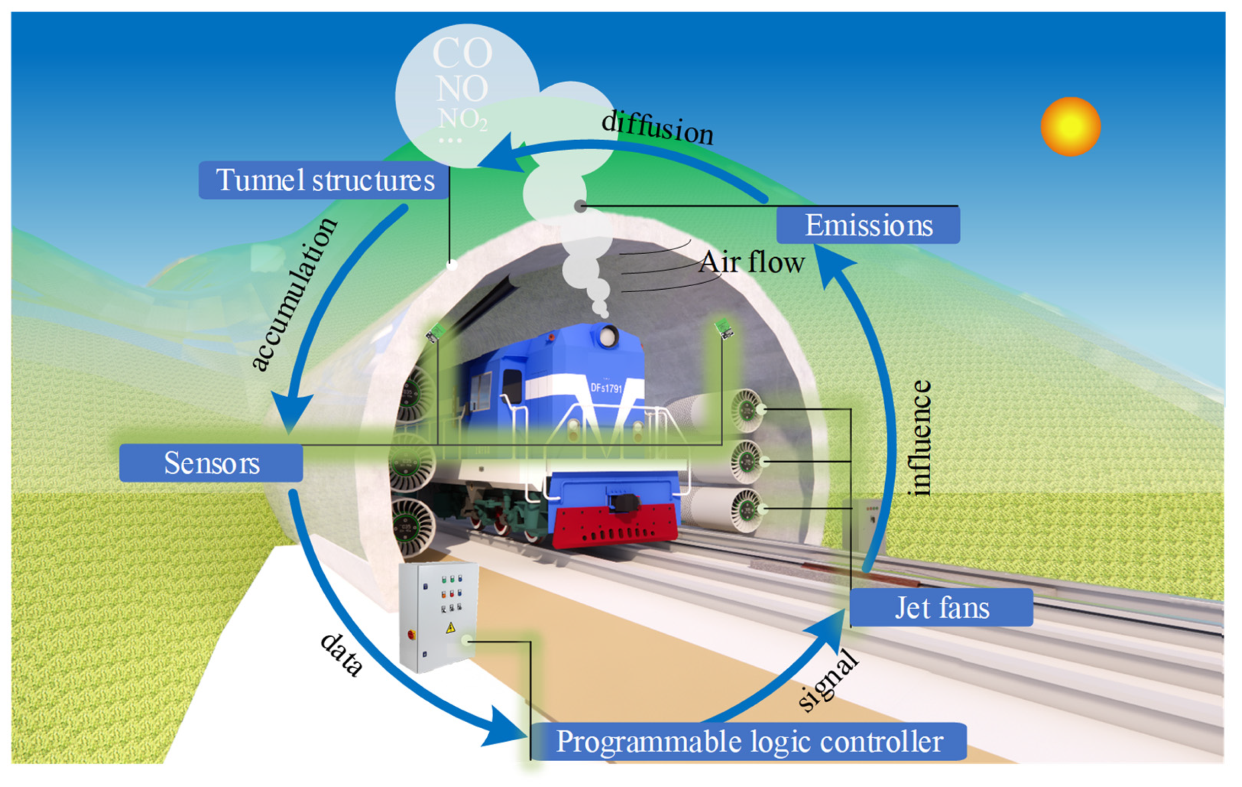
Figure 1. Components of the ventilation system of the diesel locomotive railway tunnel.
Sustainability 17 09766 g001
Figure 2. Typical tunnel ventilation structures.
Sustainability 17 09766 g002
Figure 3. A typical PLC in the tunnel ventilation system (the green arrow represents the direction of the airflow).
Sustainability 17 09766 g003
Figure 4. Installation location and working principle of the jet fans: (a) installation location of the jet fans; (b) working principle of the jet fans (the blue arrow represents the direction of the airflow).
Sustainability 17 09766 g004
Figure 5. Diagram of principles and classification of jet fans (the blue arrows represent the direction of the airflow) [39,40].
Sustainability 17 09766 g005
Figure 6. Diagram of (a) air duct [41] and (b) air curtain [42].
Sustainability 17 09766 g006
Figure 7. Classification of the tunnel ventilation system: (a) longitudinal ventilation; (b) transverse ventilation; (c) semi-transverse ventilation [43] (the blue arrows represent the flow direction of the newly introduced air, while the red arrows represent the flow direction of the polluted gas).
Sustainability 17 09766 g007
Figure 8. Concentration limits of CO in some standards of several major countries worldwide.
Sustainability 17 09766 g008
Figure 9. Concentration limits of NO in some standards of several major countries worldwide.
Sustainability 17 09766 g009
Figure 10. Concentration limits of NO2 in some standards of several major countries worldwide.
Sustainability 17 09766 g010
Figure 11. Typical scaled tunnel models: (a) scaled tunnel model with an elliptical cross-section [38]; (b) scaled tunnel model with a rectangular cross-section [39].
Sustainability 17 09766 g011
Figure 12. Diagram of the ventilation system in the Gotthard Base Tunnel [97]: (a) on-site photo of the tunnel’s internal structure; (b) schematic diagram of the overall structural composition of the tunnel.
Sustainability 17 09766 g012
Figure 13. Ventilation design study of the Nige Tunnel [99] (the non-English content means that the tunnel was constructed by PowerChina RoadBridge Group).
Sustainability 17 09766 g013
Figure 14. Diagram of the Qinling No.1 Tunnel Group [102]: (a) tunnel group location (the blue lines represent railway lines, and the yellow lines represent the locations of tunnel group); (b) overall structure of the tunnel.
Sustainability 17 09766 g014
Figure 15. Incorporating the heat generated during the tunnel drilling process into the temperature field model [27]: (a) the drilling model, (b) the control model, (c) meshes of the drilling model, (d) meshes of the control model.
Sustainability 17 09766 g015
Figure 16. Typical applications of CFD finite element simulation in tunnel engineering: (a) dust concentration peaks at 2982 mg/m3 at 1.2 m from the excavation face [108]; (b) ventilation efficiency of 0.86 under vehicle congestion conditions [109]; (c) influence range of high-temperature air exceeding 100 °C extends up to 526 m in the tunnel [110].
Sustainability 17 09766 g016
Figure 17. Different cross-section of the tunnel [131].
Sustainability 17 09766 g017
Figure 18. Schematic diagram of the air duct designed for the tunnel: (a) air ducts commonly used in highway/railway tunnels; (b) air ducts commonly used in subway tunnels (the red arrow represents the flow direction of the polluted gas).
Sustainability 17 09766 g018
Figure 19. Piston airflow field of subway vehicles in the tunnel: (a) scenario without vertical shafts; (b) scenario with vertical shafts (the blue arrows indicate the airflow direction inside the tunnel).
Sustainability 17 09766 g019
Figure 20. Xiang’an Subsea Tunnel: (a) plan layout; (b) longitudinal section [162].
Sustainability 17 09766 g020
Table 2. Concentration limits in US regulations for typical pollutant emissions within the tunnel.
IndicatorOELs (mg/m3)Notes
PC-TWAPC-STELMAC
CO55OSHA PEL
29230Cal/OSHA PEL
40.25 (10 h)230NIOSH REL
28.75ACGIH TLVs
NO30 mg/m3OSHA PEL
30Cal/OSHA PEL
30.75 (10 h)NIOSH REL
30.75ACGIH TLVs
NO29OSHA PEL
1.8Cal/OSHA PEL
1.88 (10 h)NIOSH REL
0.38ACGIH TLVs
Note: (1) All gas concentrations are expressed in mg/m3 (CO: 1 ppm = 1.15 mg/m3, NO: 1 ppm = 1.23 mg/m3, NO2: 1 ppm = 1.88 mg/m3); (2) ACGIH states that TLVs should be considered as scientific recommendations by regulatory agencies and should not be adopted as standards without full compliance with applicable regulatory procedures, including analysis of other necessary factors for appropriate risk management decisions.
Table 3. Concentration limits in AGS and DFG standards for typical pollutant emissions within the tunnel.
IndicatorOELs (mg/m3)Notes
PC-TWAPC-STELMAC
CO23AGS
35DFG
NO2.5AGS
0.63DFG
NO20.95AGS
0.95DFG
Note: The PC-TWA values for DFG in the above table were converted based on MAK calculation principles for comparative purposes.
Table 4. OELs in EU for typical pollutant emissions within the tunnel.
IndicatorOELs(mg/m3)Notes
PC-TWAPC-STELMAC
CO23117
NO2
NO20.961.91
Table 5. WHO air quality guideline values.
IndicatorOELs (mg/m3)Notes
PC-TWAPC-STELMAC
CO7 (24 h)Interim Target 1
4 (24 h)AQG level
NO
NO20.120 (24 h)Interim Target 1
0.050 (24 h)Interim Target 2
0.025 (24 h)AQG level
Table 6. Comparison of Research Methods Applied in Tunnel Ventilation Studies.
Research MethodApplicable ScenariosAdvantagesLimitations
Theoretical Analysis
  • Feasibility study and preliminary design in early project phases.
  • Rapid estimation and sizing of ventilation systems.
  • Providing theoretical framework and initial parameters for other research methods.
  • Enables quick comparison of multiple alternatives and parameter sensitivity analysis.
  • Facilitates understanding of fundamental principles and dominant factors in ventilation systems.
  • Derived formulas and conclusions possess general applicability.
  • Relies on significant simplifying assumptions (e.g., one-dimensional flow, steady-state, uniform distribution), struggling to capture complex three-dimensional flows.
  • Accuracy of results highly depends on the appropriate selection of empirical parameters such as friction and local resistance coefficients.
  • Limited capability in simulating transient, nonlinear complex scenarios like fires or traffic congestion.
Scale Model Experiment
  • Investigation of specific physical phenomena (e.g., smoke stratification, piston effect, jet fan performance).
  • Validation and calibration of numerical models.
  • Aerodynamic study of local complex structures (e.g., ramps, smoke exhaust vents).
  • Allows direct observation of physical processes like flow and smoke dispersion.
  • Highly replicates real physical mechanisms when similarity criteria are satisfied.
  • Enables systematic study of individual variables by isolating them, avoiding uncontrollable interference from real environments.
  • Difficulty in simultaneously fulfilling all similarity criteria, potentially leading to result distortion.
  • Time-consuming and labor-intensive in model fabrication, sensor deployment, and data acquisition.
  • Some measurement techniques (e.g., PIV) may disturb the flow field and obtaining full-field data is challenging.
Field Test
  • Final verification of the effectiveness and reliability of ventilation system design.
  • Performance evaluation and optimization potential assessment of existing tunnel ventilation systems.
  • Study of the most realistic and complex operational conditions (e.g., fire, traffic congestion).
  • Reflects the combined influence of tunnel structure, traffic flow, and environment, providing the most credible results.
  • Yields first-hand real-world data, avoiding errors introduced by model scaling.
  • Involves high costs and safety risks, particularly for fire tests requiring traffic closure.
  • Susceptible to external factors like weather and traffic conditions, making specific scenario replication difficult.
  • Limited measurement points hinder acquisition of complete, detailed spatial field data.
  • Typically conducted only after system construction, limiting utility for preliminary design optimization.
Numerical Simulation
  • Full-scale, three-dimensional detailed simulation of flow, mass, and heat transfer processes in tunnels.
  • Fire dynamics simulation (smoke spread, temperature distribution, visibility change).
  • Detailed optimization and comparison of ventilation schemes.
  • Provides comprehensive data for all variables across the entire flow field (velocity, pressure, temperature, pollutant concentration, etc.).
  • Offers high flexibility in modifying geometry, boundary conditions, and scenarios without physical constraints.
  • Significantly reduces research and optimization costs compared to field and model experiments.
  • Exhibits good predictive capability, especially for pre-evaluating hazardous scenarios like fires.
  • High-fidelity, large-scale computations demand substantial computational resources and time.
  • Accuracy depends on the selection of models (e.g., turbulence, combustion) and requires validation against theoretical or experimental data.
  • Susceptible to numerical errors influenced by discretization schemes and mesh quality, demanding high user expertise.
Disclaimer/Publisher’s Note: The statements, opinions and data contained in all publications are solely those of the individual author(s) and contributor(s) and not of MDPI and/or the editor(s). MDPI and/or the editor(s) disclaim responsibility for any injury to people or property resulting from any ideas, methods, instructions or products referred to in the content.