Article

An Integrated Strategy for Pre-Disposal of Spent Cation-Exchange Resins by Repurposing Industrial By-Products

1
Laboratory of Radiochemistry and Radiation Chemistry, Department of Energy, Politecnico di Milano, Via La Masa 34, 20156 Milano, Italy
2
Laboratory of Catalysis and Catalytic Processes, Department of Energy, Politecnico di Milano, Via La Masa 34, 20156 Milano, Italy
3
Hydrogen Laboratory, Department of Chemistry, University of Pavia & C.S.G.I., Viale Taramelli 16, 27100 Pavia, Italy
4
Department of Earth Sciences, University of Milan, Via S. Botticelli 23, 20133 Milano, Italy
5
Joint Research Centre, European Commission, Via E. Fermi 2749, 21027 Ispra, Italy
*
Author to whom correspondence should be addressed.
Sustainability 2025, 17(18), 8241; https://doi.org/10.3390/su17188241
Submission received: 9 June 2025 / Revised: 27 August 2025 / Accepted: 9 September 2025 / Published: 13 September 2025
(This article belongs to the Special Issue Waste Management for Sustainability: Emerging Issues and Technologies)

Abstract

Large amounts of spent, radioactive, ion-exchange resins have been generated worldwide, and their production is expected to grow due to a renaissance of nuclear power. Such waste is being stored at individual plant sites around the world, awaiting a reliable disposal route to overcome the downsides of the state-of-the-art management approaches. In this work, a first-of-its-kind pre-disposal strategy is proposed, based on the integration of a heterogeneous Fenton-like treatment with conditioning in an alkali-activated matrix. In particular, the circular economy is pursued by repurposing two industrial by-products, coal fly ash and steel slag, both as catalysts of the Fenton treatment and precursors of the conditioning matrix. The obtained waste forms have been preliminarily tested for leaching and compressive strength according to the Italian waste acceptance criteria for disposal. The proposed technology, tested at laboratory scale up to 100 g of virgin cationic resin, has proven successful in decomposing the waste and synthesizing waste forms with an overall volume increase of only 30%, thereby achieving a remarkable result compared to state-of-the-art technologies.

Graphical Abstract

1. Introduction

Spent ion-exchange resins (SIERs) are routinely generated upon decontamination of reactor coolant, spent fuel pools and wastewater, and 3000–5000 m3 of SIERs are estimated to be produced yearly from the nuclear power plant currently in operation [1]. Even though SIERs are regenerable [2], such a procedure is discouraged due to the great volumes of secondary waste and the contamination of the SIERs, along with their stepwise decomposition by the harsh operative conditions, namely high temperature and radiation fields [3]. From the point of view of their disposal, SIERs are classified as a challenging waste due to their organic content, flammability, dispersivity in embedding matrices, and leachability of contaminants to the biosphere. Currently, two approaches for the disposal of SIERs are pursued [4]: (i) direct conditioning in a matrix; (ii) degradation of the organic components and conditioning of the obtained residues. While the first option is conceptually easy and exhibits relatively low pre-disposal costs, about a five- to six-fold increase in volume [4] is produced, resulting in high costs associated with the final disposal in repositories [5].
The main issue experienced when direct cementation is pursued is the volumetric instability of the resin beads/powders, which swell and shrink during hardening of the cement mortars undergoing hydration, causing internal stresses with detrimental effects; in addition, cemented forms exhibit questionable durability due to the poor resistance towards corrosion and thermal stresses [4,6]. These issues can be coped with by changing the conditioning matrix. For instance, alkali-activated materials and geopolymers are endowed with better resistance towards aging, leaching and other phenomena, thus resulting in a more suitable matrix for the encapsulation of radioactive waste than cement-based pastes [7,8]. Moreover, these classes of materials exhibit improved flexural strength, a key property required to contrast the swelling and shrinkage of SIERs [9,10,11]. In these regards, recent developments have shown that more sophisticated approaches may allow direct encapsulation of SIERs in alkali-activated matrices, achieving greater loading factors, halving the resulting volumes to be disposed of compared to traditional cementation [12]. However, given the high costs associated with the occupancy of the repositories, the volumetric reduction in the resulting waste forms is worth further pursuing, at the expense of more complex procedures and greater use of economic and material resources in the pre-disposal steps. This can be performed by coupling waste treatment processes with the conditioning of the resulting residues. In this regard, common treatment processes for the decomposition of the organic matter content of SIERs could be divided into wet and dry oxidation techniques, with the former including Fenton and Fenton-like processes, supercritical water oxidation, boiling degradation in acid or hydrogen peroxide, and plasma technologies, while the latter includes pyrolysis and incineration [1,4]. Among these, Fenton and Fenton-like processes are attractive due to low operating temperatures and the non-toxic, readily available reagents employed. As reported in previous works, the cationic species (e.g., Fe, Co, Ni, Sr, and Cs) remain in the liquor downstream of the Fenton treatment. On the contrary, the anionic volatile species (e.g., C, Cl, I) are lost in the off-gas and would require dedicated off-gas treatment [13,14]. Conversely, in dry oxidation processes, the volatilization of some cationic species may also occur [3].
The Fenton process in homogeneous conditions is a well-established, effective route of wastewater treatment and removal of recalcitrant organic pollutants [15,16]: it employs a ferrous catalyst and hydrogen peroxide to produce hydroxide radicals, which interact with the targeted pollutant. Some applications to surrogate SIERs can be found in the literature, with encouraging results from Xu et al. [17] and Meng et al. [18], reporting mass reductions of 73% and 79%, respectively. The implementation of this treatment on a larger scale is, however, inhibited due to some disadvantages: very acidic environments, iron sludges to be further treated, great consumption of catalyst and substantial final volumes. Moreover, scarce compatibility between the residue and the conditioning matrix, and poor durability of the waste forms have been reported [5,13].
The complexity of this treatment process is based on the balance of different aspects, such as iron speciation, oxidative power of reactive oxygen species (ROS), interactions among intermediate species and the reaction environment, and competitive reactions. Sub-optimal iron speciation could result in the inhibition of bivalent iron regeneration and consequent interruption of the reaction due to its unavailability. Furthermore, the presence of organic intermediates of degradation can enhance iron precipitation [4,19,20]. Many parameters, such as initial pH, temperature, oxidant rate, mixing speed, catalyst type and concentration, and reaction time, can be finely tuned to improve the performance of the process, without completely solving the aforementioned issues. In wastewater treatment [16,21], a possible solution to such issues is provided by the implementation of the Fenton-like process in heterogeneous conditions, i.e., using a solid catalyst. Iron minerals, zero-valent iron powders [16], iron oxides, iron-loaded clays, and iron-rich industrial by-products [22,23,24,25] are all viable candidates as heterogeneous catalysts. This variety of sources and characteristics, combined with an extension of operative pH ranges, reusability of the catalyst, and limited sludge production, results in an improvement of the limitations of the homogeneous process. On the other hand, a greater degree of complexity arises, which is linked with a plethora of ROS, like hydroxyl radical, hydroperoxyl radical, superoxide anion and high-valent iron species. Indeed, these compounds are commonly responsible for the degradation of the organic matter by following two different proposed mechanisms [26]: homogeneous Fenton induced by leached iron and heterogeneous catalysis on the surface.
Among the possible heterogeneous catalysts, coal fly ash (CFA) and electric arc furnace slag (EAFS) have been selected for this work. Indeed, in addition to SiO2 and Al2O3 with their co-catalytic roles, these materials show an important catalytic effect thanks to the considerable contents of iron oxides [27]. Upwards of 500 million tons of CFA are yearly produced worldwide, of which only 25% to 30% are recycled, mainly in the construction sector [28,29,30,31,32,33]. The successful employment of CFA and EAFS as catalyst for a Fenton-like treatment of SIER, so far to the best of the authors’ knowledge is undocumented, and encourages circular economy purposes, exploiting numerous features of these materials [21,34,35,36]: large availability, low cost, good chemical properties and tunability, ease of reutilization without high degradation of catalytic properties, wider pH ranges of utilization, and absence of iron sludges to be further processed. This work, developed within the EU-H2020 PREDIS (PRE-DISposal management of radioactive waste) and EURAD-2 (European Joint Programme on Radioactive Waste Management) projects [37,38], aims to propose an innovative strategy for the disposal of SIERs based on the integration of a Fenton-like oxidation with the encapsulation in a non-cementitious matrix of the residues. In performing so, reduced volumes of the final waste forms are obtained, at the same time repurposing and recycling significant amounts of industrial by-products. To pursue this integrated strategy, the work was divided into two main phases: treatment and conditioning. The treatment phase consisted of a proof-of-concept regarding the use of industrial by-products for the Fenton-like treatment of SIERs, followed by an upscale of such a process and the characterization of the produced residue. The conditioning phase consisted of the encapsulation of the obtained inorganic residue into an ad hoc alkali-activated matrix, designed and developed in this work. The present study ended with a preliminary qualification of the produced waste forms according to Italian acceptance criteria for disposal [39]. The integration of the two phases was addressed by using the spent catalyst found in the residue downstream of the Fenton-like process as one of the matrix precursors for the conditioning of the residues, thus aiming for a sustainable approach, high loading factors, and satisfactory properties of the resulting waste forms.

2. Materials and Methods

2.1. Materials

The treatment was performed on simulated SIER, namely the AmberliteTM IRN77 cationic resins used by nuclear facilities (produced by DuPont, Wilmington, DE, USA, and supplied by Idreco Srl, Voghera, Italy). The technical data of the cationic resin are reported in the Supplementary Materials (Table S1).
Two different catalysts were tested: CFA (class-F according to ASTM C618-22 [40]) and EAFS. Their investigation was performed by X-ray fluorescence (XRF) spectroscopy, X-ray powder diffraction (XRD), scanning electron microscopy (SEM), and N2 adsorption–desorption. The results of these characterizations are reported in the Supplementary Materials (Table S2, Figures S1 and S2).
Hydrogen peroxide (35 wt.% technical-grade solution, Chimitex Spa, Fagnano Olona, Italy) was used as oxidant in the Fenton-like treatment. If needed, concentrated sulfuric acid (96 wt.% analytical-grade, Carlo Erba Srl, Cornaredo, Italy) was used to adjust the initial pH value of the Fenton batches [4,13,19,20].
To prepare the alkali-activated matrix, volcanic tuff (Zeolite FerteniaTM, provided by Fertenia Srl, Bellizzi, Italy), the same EAFS and CFA, and ground-granulated blast-furnace slag (BFS, provided by Buzzi Unicem Srl, Casale Monferrato, Italy) were combined with alumina (analytical-grade powder, Merck, Darmstadt, Germany) and sodium hydroxide (technical-grade pellets, Marten Srl, Maierato, Italy). All these reagents and materials were employed without further processing. The results of the X-ray fluorescence (XRF) characterization of these materials are reported in Table S2.

2.2. Fenton-like Wet Oxidation

This treatment step consisted of a heterogeneous Fenton-like wet oxidation. For each of the two proposed catalysts, the study was divided into a proof-of-concept, namely the treatment of 10 g of synthetic SIERs (as described in the Supplementary Materials) [4,13,14,17,18,19,20,26,41,42,43,44], and in the upscaling to 100 g of simulated SIERs. During the proof-of-concept step, the aim was to assess the feasibility of the heterogeneous wet oxidation of surrogate SIERs by looking for a range of operating conditions for its optimization in terms of mass and carbon content reductions. This was pursued by individually tuning initial temperature and pH values, oxidant injection rate, type and mass of catalyst, and reaction time.
The experimental setup consisted of a glass four-necked round-bottom flask immersed in an oil thermal bath. The temperature of the bath was controlled with a hot plate and measured with a thermometer. A second thermometer was used to monitor the temperature of the mixture within the flask, which was stirred with a magnetic rod powered by the hot plate. The oxidant was fed by a Gilson Minipuls 3 (Gilson Inc., Middleton, WI, USA) peristaltic pump. Finally, the off gases were fluxed through a condenser.
To start the wet oxidation treatment, the surrogate SIER and catalyst were carefully weighed and poured into the flask with ultrapure water to allow for mixing. About 280 mL of ultrapure water was added for 100 g of resins. The mixture was then stirred at a speed between 200 and 250 rpm and brought to the defined start-up temperature (65 ± 1 °C). When the starting temperature was reached, the pH value was checked and adjusted if necessary. After concluding preliminary steps, the peristaltic pump was switched on to inject oxidant at rates of 1.5 mL/min and 2.2 mL/min for 100 g of resins and trigger the reaction. The evolution of the temperature and the color of the mixture was monitored over time. At the end of the process, an aliquot of the resulting liquor was collected for characterization. Namely, gas chromatography–mass spectrometry (GC-MS) was conducted to determine the products of the reactions. Finally, the resulting liquor was transferred to a beaker and evaporated without exceeding 75 °C to avoid leakages and spillages due to intense boiling [13]. The time required for the evaporation of the liquor varied according to the volume, which, in turn, depended on the reaction time and the volume of water used to rinse the flask during the decanting. Once the dried residue was obtained, the mass reduction ratio (MRR) was preliminarily considered as a parameter for the optimization of the process, and assessed as follows:
MRR = m resin m residue m catalyst m resin
where m resin is the initial mass of the resin to be treated, m residue is the mass of the dried residue, and m catalyst is the catalyst mass. In Equation (1), m catalyst is assumed to be constant throughout the Fenton treatment.
Another parameter used for process optimization is the carbon content reduction C reduction , assessed via an elemental carbon analyzer and computed as follows:
C reduction = C resin C residue C resin
where C resin and C residue represent the carbon content of the initial organic resin and that of the residue obtained downstream of the treatment step, respectively.

2.3. Conditioning of the Residues

The starting point for the synthesis of the matrix was a recipe previously developed [45,46], in which EAFS was introduced as a further ingredient. Because of the acidity of the residues downstream of the treatment, the latter were pre-mixed with sodium hydroxide, at least up to pH 10, not to affect the alkalinity of the matrix [13]. For this step, it was found that 0.4 g of sodium hydroxide was needed to raise the pH of 1.0 g of residue to about 11–12. This result is consistent with the procedure reported in a previous work [13]. Such a basification was carried out in an ice bath to avoid temperature increase due to the exothermicity of the processes. The loading factor of the treated resin, LF conditioning , in the waste form was computed as follows:
LF conditioning = m residue m catalyst m grout
where the numerator is the mass of the residue downstream of the treatment and evaporation stage, free of the mass of catalyst, and m grout is the mass of the resulting fresh grout. The mass m grout in Equation (3) accounts for the depleted catalyst found in the residue (considered as a precursor), the fresh matrix precursors and activators, and the extra sodium hydroxide and water needed for the neutralization/basification of the Fenton residue.
To eventually prepare the waste forms, the weighed amounts of solid NaOH and powdery precursors were first homogenized, and water was added afterwards to start the reaction. Following the mixing of the paste according to the EN 196-1 procedure for 10 min [47], the pre-alkalinized residue was introduced at room temperature, and the grout was further mixed for 5 min prior to casting it in cubic (5 cm) and cylindrical (equilateral, 3 cm) molds. The quantities of the materials and reagents are reported in Table 1. The specimens were demolded after 14 days to complete the 28-day curing at 22 ± 1 °C (at relative humidity greater than 90%).
The key concept behind the encapsulation of the treated residues is to repurpose the depleted catalyst found downstream of the Fenton-like treatment as a matrix precursor, thus partially replacing the fresh materials and reducing their need. The extent to which this replacement takes place depends on the factor LF conditioning : the higher the loading factor, the lower the need for fresh CFA and EAFS.

2.4. Testing of the Waste Forms

A stepwise approach was followed to assess the durability of the waste forms. To screen among the encapsulation factors and the recipes, a preliminary, static immersion in de-ionized water was carried out on cylindrical specimens over a period of two weeks, at 22 ± 1 °C. The ratio of the volume of water to the surface area of the specimen was 10 cm. Downstream of the immersion, specimens were retrieved and left to dry prior to visual inspection to check for cracks and/or crumbles.
Specimens of formulations withstanding the static immersion were reprepared for characterization of their performances by means of compression and lixiviation in ultrapure water, according to the guidelines of the Italian regulatory body [39]. Cubic specimens underwent uniaxial compression following the EN 12390-1:2021 [48] and EN 12390-3:2019 [49] protocols, applying a loading rate within the range 0.6 ± 0.2 MPa/s. The short-term, semi-dynamic lixiviation of waste forms was performed on cylindrical specimens according to the ANSI/ANS-16.1-2019 protocol [50]. The ultrapure water employed as leachant was replaced every 24 h for a total of 7 days of testing. Leachates were analyzed via inductively coupled plasma optical emission spectroscopy (ICP-OES, Avio™ 500 spectrometer, Perkin Elmer, Milano, Italy) to assess the release of Na, Ca, Al, Si and S. The leachability indices for these chemical species were computed according to the ANSI/ANS-16.1-2019 protocol [50].

2.5. Characterization

Oxidation products present in the final liquor were analyzed by gas chromatography–mass spectrometry (GC-MS, Agilent 6890 with 5973 MSD, Agilent Technologies, Santa Clara, CA, USA), using a HP-5MS column (length 30 m, diameter 0.25 mm, and thickness 0.25 μm). The carrier gas was high-purity (99.99%) helium and a split ratio of 10:1 was used for the injections. The initial temperature was 40 °C (held for 3.5 min) and ramped at a rate of 6.0 °C/min to 280 °C (held for 2 min), and to 300 °C (held for 15 min). The injector and quadrupole temperatures were 250 °C and 150 °C, respectively [51]. The observed mass spectra were compared to the NIST spectral library for the identification of the species. The relative concentration of the detected species was estimated using the peak area percentage, calculated by area integration of each observed peak normalized by the total area of all peaks.
Elemental carbon content was assessed using a multi-EA 4000 elementary analyser (Analytik Jena GmbH+Co. KG, Jena, Germany) calibrated with standards of anhydrous calcium carbonate in the range 10–250 mg. In operative conditions, the furnace was at 1200 °C, the oxygen flux was 2.3–2.5 L/min, and the extraction pump flux was 1.7 L/min. The samples (maximum 3 g each), such as virgin cationic resin, coal fly ash, electric arc furnace slag, and the obtained residues, were analyzed without any pre-treatment. Results were processed with the associated multiWin software (v. 5.3.3, 2013) suite (Analytik Jena AG).
Elemental composition of powders was assessed by XRF using an EDX-8100P energy dispersive spectrometer (Shimadzu Srl, Milan, Italy), in agreement with the EN 196-2:2013 standard, using a micro-powder wax (Hoetsch Wax C, Supelco, Merck, Darmstadt, Germany) as a binding agent [52]. Prior to that, the powders under analysis were dried in an oven, and the water content was assessed by gravimetric measurement after bringing the samples to 115 °C until constant mass.
XRD investigation was carried out to identify the phases present in the powdery catalysts and precursors, the wet oxidation residues, and the synthesized waste forms. For the latter, grinding in agate mortar was performed, as described in previous works [34,35]. X-ray diffraction patterns were collected with an automated Panalytical X’Pert Pro-diffractometer (Malvern Panalytical, Lissone, Italy), equipped with a X’Celerator-type detector, employing a monochromatized Cu-Kα source. Additional details are: 2ϑ range between 4 and 80° with a step size of 0.017°, 40 kV and 40 mA, and a counting time of 240 s per step. Phase identification was performed using the X’pert HighScore suite.
Elemental analysis was performed on the leachates to assess the release of chemical species from the waste forms. Aliquots of the samples were acidified with concentrated nitric acid (Analitika Analpure®, Analytica Spol. Sro, Prague, Czech Republic) and duly diluted with a solution of ultrapure nitric acid in Milli-Q water (MilliporeSigma, Merck, Darmstadt, Germany). The analyses were performed with an Avio 500 spectrometer (Perkin Elmer) calibrated with CMS-x Ventures multi-element standards in the range 10−1–102 mg/L.
The porosity of the waste forms was assessed via Mercury Intrusion Porosimetry (MIP) with an Autopore IV 9500 mercury intrusion porosimeter by Micromeritics. Samples of approximately 0.5 g were left vacuum-dried for 24 h at room temperature following the 28-day curing. After retrieval, the specimens were ground in the 1–2 mm range and placed in the porosimeter bulb, where pressure was applied in the range 1–200 MPa. The porosity was derived with the Washburn equation, assuming a sample-mercury contact angle of 130° [13].
Nitrogen adsorption–desorption analyses were performed at 77 K with a 3Flex analyzer (Micromeritics, Norcross, GA, USA). Prior to the measurement, samples were pretreated in nitrogen flux (2 h at 100 °C) using a FlowPrep apparatus (Micromeritics, Norcross, GA, USA), and then degassed in situ (2 h at 100 °C under vacuum), directly on the 3Flex ports: these steps enabled the removal of impurities and humidity from the surface. The total specific surface area was calculated with the Brunauer–Emmett–Teller (BET) method [53], while the pore volume was estimated with the Barrett-Joyner-Halenda (BJH) method (adsorption branch).
A Zeiss EVO MA10 (Carl Zeiss, Oberkochen, Germany) microscope was used to perform scanning electron microscopy (SEM). The samples were gold-sputtered for the morphological analysis and observed at a working distance of 8.5 mm, collecting the secondary electrons signal.

2.6. Efficacy of the Management Strategy

The derivation of the increase in volume of the pre-disposal strategy for radioactive waste is very useful to take into account the costs associated with the volumetric occupancy of a waste repository. Accordingly, the volume increase factor V increase is defined as the ratio of the volume of fresh waste form ( V grout ) to the volume of starting waste, in this case that of the resins ( V resin ):
V increase = V grout V resin
Similarly, the volume increase factor in Equation (4) can be expressed in terms of both the treatment and conditioning outputs by taking advantage of Equations (1) and (3) and considering the densities of the resin ( ρ resin ) and of the grout ( ρ grout ), thus returning
V increase = 1 MRR LF conditioning × ρ resin ρ grout
Another way to evaluate the efficacy of the management strategy, which allows straightforward comparison with the conventional approaches based on direct conditioning, is through the equivalent loading factor for the resin beads in the waste form ( LF resin ), which can be defined as follows:
LF resin = m resin m grout   = LF conditioning 1 M RR
The emphasis should be put on the term equivalent. Indeed, LF resin in Equation (6) represents the loading of the treated waste as if it was not treated. From a conceptual point of view, LF resin is expressing the mass evolution of the form to be disposed of throughout the pre-disposal steps.

3. Results and Discussion

3.1. Fenton-like Wet Oxidation

The outcomes of the small-scale tests are described, discussed and depicted in the Supplementary Material (Table S4, Figures S4–S9) [4,13,17]. They served as the basis for the laboratory upscale tests (100 g of simulated SIER), where oxidant and catalyst amounts were changed, while the initial temperature and pH conditions were kept the same (Supplementary Materials). A similar evolution of the mixture was observed. Over time, the color of the mixture, indeed, shifted from dark brown to yellow (Figure 1), consistent with the complete dissolution of the surrogate SIERs.

3.1.1. Oxidant Rate

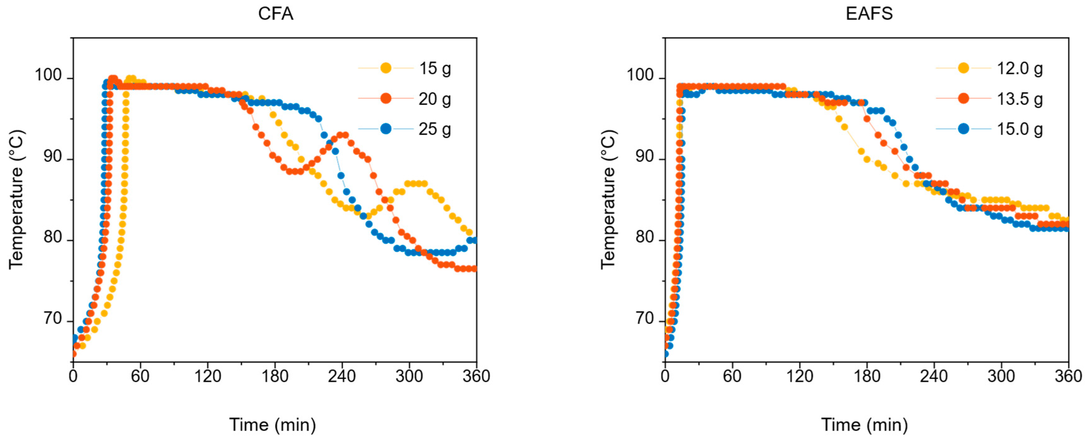
The tests were performed with oxidant rates of 1.5 mL/min and 2.2 mL/min [13]. In the case of the lower rate, a longer time to reach peak temperature and lower reactivity of the reaction were observed. The obtained residues were considerably different from those obtained at the small scale. Based on these experimental findings, a shortage of oxidant was supposed. Indeed, with the increase in the oxidant rate up to 2.2 mL/min, those undesired effects were overcome, as shown in Figure S7b. The system reactivity was restored, resulting in an increased peak temperature and duration, especially at higher catalyst masses, showing that an insufficient oxidant rate can prematurely halt the reaction (Figure 2, left). These considerations were supported by the results of the MRR and C reduction evaluated via an elemental carbon analyzer.
A significant improvement of MRR and total carbon reduction was achieved when the oxidant rate was increased, in particular when using EAFS as a catalyst (Table 2). This change was conducted by keeping constant the catalyst mass and the reaction time of around 6 h.

3.1.2. Catalyst Mass

An optimization of the masses of catalyst was performed with respect to small-scale tests (10 g of synthetic SIER). To treat 100 g of simulated SIERs (resin mass scale factor of 10), different amounts of CFA and EAFS were investigated. During these evaluations, the opportunity of greatly limiting the required amount of CFA was noted (CFA mass scale factor of 3, i.e., three times the amount of CFA used in the small-scale experiments, against the expected mass scale factor of 10) to reach an MRR value of 65%, and a total carbon reduction of around 96%. On the other hand, EAFS proved to be less effective under these experimental conditions (EAFS mass scale factor of 10).
When dealing with CFA, an increase in the mass of the catalyst resulted in an extended peak temperature from 111 to 147 min (Figure 2, left), respectively, for 15 g and 25 g of CFA; furthermore, for lower masses (i.e., 15 g and 20 g), an oscillating behavior was found, with secondary peaks at 4 h (20 g) and 5 h (15 g) from the beginning of the reaction. On the other hand, when using EAFS, the process evolution was different. Once the maximum temperature of 99 °C was reached, a plateau was maintained for up to 3 h, followed by a smooth and monotonous decrease, as shown in Figure 2 (right). Generally, the duration of the plateau seemed to increase with catalyst mass. Nevertheless, the values of MRR and C reduction are comparable, showing that the reactions performed with an increased 2.2 mL/min oxidant rate were effective. Nevertheless, the choice of the optimal conditions for the process was made based also on the following operative aspects:
  • ▪ ease of manipulation of the catalyst and availability;
  • ▪ ease of peak control, by avoiding accumulation of unreacted H2O2;
  • ▪ widening of the region at peak temperature, avoiding oscillating behavior of the process with multiple secondary peaks, thus allowing a complete mineralization of the resins;
  • ▪ obtaining a residue easily workable and compatible with the conditioning matrix for encapsulation.
Based on these experimental findings, the chosen optimal conditions (Figure 2) were 67 ± 2 °C as start-up temperature, 1.5 as pH value, 2.2 mL/min of oxidant rate, 15 g of EAFS or 25 g of CFA as catalyst, and 6 h of reaction time. Tests with such conditions were conducted in triplicate, showing nearly identical temperature profiles, MRR and C reduction values, as reported in Table 3.

3.1.3. Characterization of the Fenton Liquors

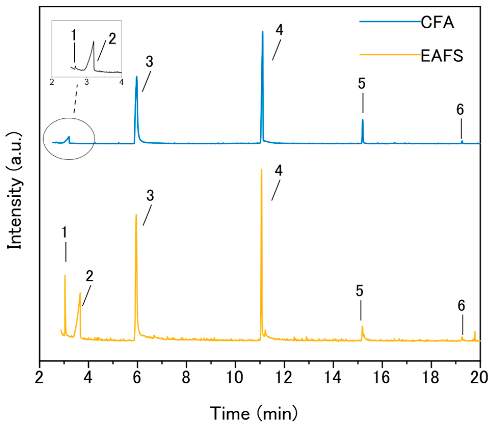
Figure 3 shows the GC-MS chromatograms of the final liquors of the two samples, CFA and EAFS, at optimal conditions. The analyses revealed the presence of light final reaction products such as oxalic acid, formic acid and acetic acid, demonstrating an effective decomposition of surrogate SIERs. Furthermore, the long final products coming from the first polystyrenic oxidation process generally reported in the literature [54,55] were not detected in this work. Interestingly, heavy cyclic siloxanes were found, in particular cyclotrisiloxane, hexamethyl- (Silox-3, with three silicon atoms), cyclotetrasiloxane, octamethyl- (Silox-4, with four silicon atoms), cyclopentasiloxane, decamethyl- (Silox-5, with five silicon atoms) and cyclohexasiloxane, dodecamethyl- (Silox-6, with six silicon atoms). The formation of these products is ascribed to the massive presence of Si in CFA and EAFS catalysts, which may be leached over the treatment and made available to take part in the oxidation reactions of organic matter, being the catalysts the only sources of Si in the system. The same species were identified in all the liquors of other samples from treatment at different operating conditions, as reported in the Supplementary Material. To the best of the authors’ knowledge, there is no evidence of similar species in the liquors coming from Fenton treatment of SIERs commonly reported in the literature.
It is worth noting that the samples showed a variation in the relative abundance of these species: the quantification of the percentage peak area reported in Table 4 indicates a larger presence of heavy siloxanes in sample CFA with respect to sample EAFS; an opposite trend is observed for the light oxygenates. This evidence can be ascribed to the fact that the amount of SiO2 in CFA catalyst is almost five times higher than that of EAFS, so Si will be much more available over the treatment process. Further results obtained at different operating conditions are reported in the Supplementary Material (Figure S3 and Table S3).

3.1.4. Characterization of the Fenton Residues

The X-ray diffraction patterns of the residues obtained from the evaporation of the liquor downstream of the treatment are reported in the Supplementary Materials. Both the residues comprise a substantial fraction of amorphous material. For the CFA-based residue, the X-ray diffraction peaks are associated with the following crystalline species: dominant anhydrite CaSO4 and rhomboclase H5Fe3+O2(SO4)2·2(H2O), quartz SiO2, and probable voltaite K2Fe2+5AlFe3+3(SO4)12·18(H2O). Concerning the EAFS-based residue, the Bragg peaks are associated with dominant anhydrite CaSO4, gypsum CaSO4·2(H2O) and rhomboclase H5Fe3+O2(SO4)2·2(H2O), quartz SiO2, bassanite CaSO4·0.5(H2O), szomolnokite FeSO4·H2O, and probable voltaite. The peak of wüstite FeO is not present because the Fe(II) is more likely to be oxidated into Fe(III) during the Fenton-like treatment [56]. The oxidation of the iron also explains the presence of a complex mixture of crystalline species containing trivalent iron.

3.2. Conditioning in the Alkali-Activated Matrix

3.2.1. Conditioning and Preliminary Qualification

Specimens with LF conditioning equal to 6, 12, and 18 wt.% were prepared for both the catalysts (Figure S9 of the Supplementary Materials). The residues used for this purpose are the ones obtained from the optimal conditions of treatment, namely 25 g of CFA and 15 g of EAFS, with 2.2 mL/min of H2O2. The main findings are reported in Table 5.
After 28 days of curing, all the specimens hardened and underwent preliminary qualification by static immersion in water to simulate flooding of the waste repository. It was found that at 18 wt.% LF conditioning , both specimens containing CFA- and EAFS-based residues did not withstand the immersion; they cracked and partially dissolved within 12 h from the beginning of the immersion. The same occurred for the specimens loaded with 12 wt.% LF conditioning of EAFS-based residue. Such recipes were thus discarded and not further tested.

3.2.2. X-Ray Diffraction Patterns

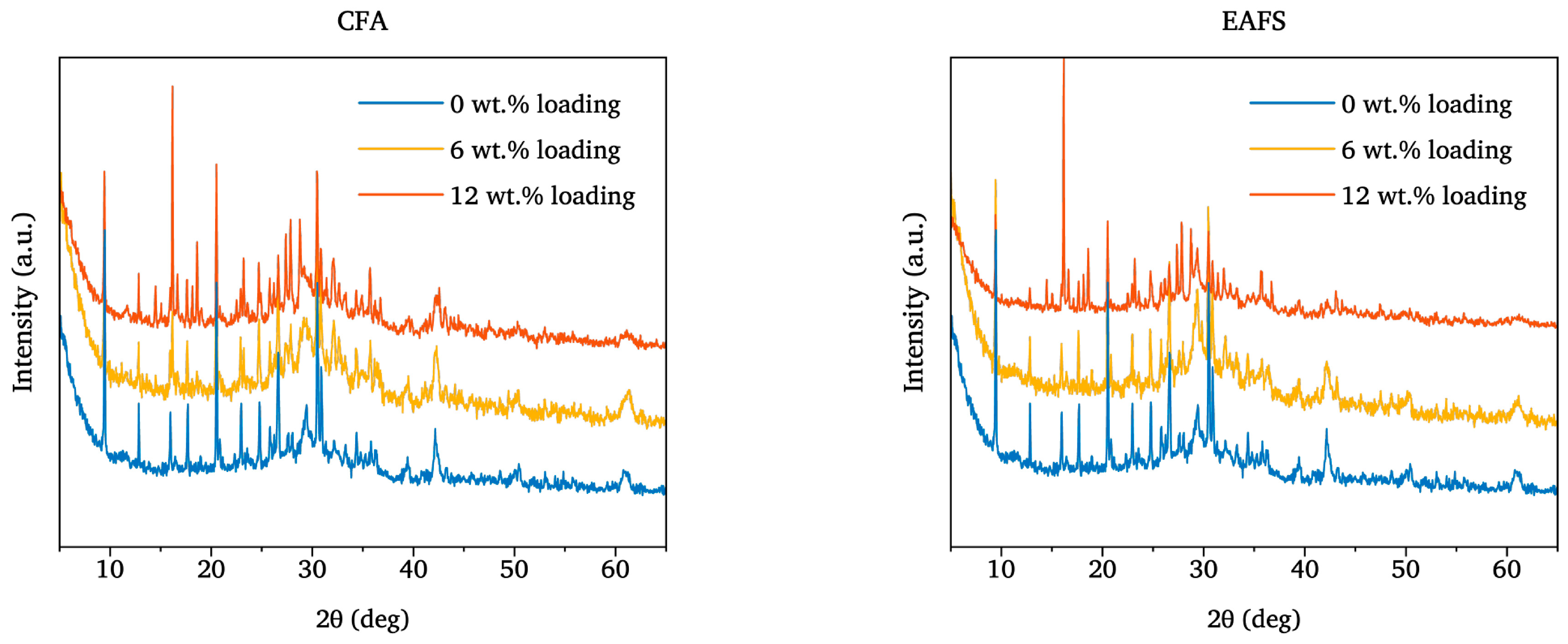
The X-ray diffraction patterns of the matrix, reported in Figure 4, show a substantial fraction of amorphous phase, with Bragg peaks associated with the following crystalline species: dominant zeolite chabazite |(Ca0.5,K,Na)x(H2O)12|[AlxSi12−xO24] (x: 2.4–5.0) and quartz SiO2, and subordinate zeolite phillipsite |(Ca0.5,Na,K)x(H2O)12|[Al xSi16−xO32] (x: 4.1–6.8), calcite CaCO3, wüstite, K-feldspars KAlSi3O8 and mullite Al6Si2O13. The zeolites chabazite and phillipsite and the K-feldspars come from the precursor volcanic tuff [46], while the mullite and quartz and the wüstite are unreacted phases from the CFA [57] and the fresh EAFS [58], respectively.
The diffraction patterns of the specimens loaded with the CFA-based residue (Figure 4, left) exhibit a consistent degree of amorphousness, with Bragg peaks related to dominant zeolite chabazite and to quartz, K-feldspar, mirabilite Na2SO4·10(H2O), calcite, and wüstite. Similarly, the diffraction patterns of the waste forms loaded with the EAFS-based residue (Figure 4, right) identify a consistent fraction of amorphous phase in the hardened specimens, with Bragg peaks ascribable to dominant quartz and zeolite chabazite, and to calcite, vaterite CaCO3, thenardite Na2SO4, larnite β-Ca2SiO4 and wüstite. The relative intensity of the peaks of wüstite (reference peak around 42° 2θ values) decreases with increasing waste loading, as EAFS in the recipe decreases as well (Table 1). In addition, wüstite can be partially oxidized into Fe(III)-bearing phases, altering the reactivity towards the alkalination and geopolymerisation processes and contributing to the amorphous signal of the diffraction pattern [59,60]. On the contrary, the relative intensity of the peaks of mirabilite (reference peak around 16° 2θ values) increases with increasing waste loading [13]. In addition, mirabilite and thenardite phases were observed as the dominant products of the migration of Na+ and OH in a geopolymeric network [61].

3.2.3. Compressive Strength

Upon hardening, the compressive strength of the matrix (Table 5) resembled the one of the previous work [13]. This supports the potential use of EAFS as a precursor for the synthesis of alkali-activated and geopolymeric materials [62]. The compressive strength of the waste forms decreases with increasing LF conditioning , as reported in Table 5. This decline can be to a small extent attributed to an increase in porosity after loading the residue [13]. However, the reduction in compressive strength cannot be solely explained by the slightly increased porosity [13,63]. First, the amount of binder decreases, thus reducing its contribution to setting and hardening. In addition, because of the neutralization of the waste with NaOH, there is a significant alteration of the stoichiometry of the recipe, with the Na/Al ratio, which becomes significantly imbalanced [64,65,66]. Another factor affecting the mechanical properties of the waste forms is the waste residue interacting with the activator (NaOH) and promoting the formation of mineralogical phases, especially thenardite and mirabilite, which do not help the mechanical properties of the waste forms [61]. Eventually, there may be interference of some chemical species within the residue, such as the sulfates, with the processes of alkalination and condensation [67,68]. Concerning the interaction of the possible residual organics found in the residue downstream of the Fenton-like treatment (Figure 3), there is relatively little literature. To the best of the author’s knowledge, no works related to the effects of organic acids and organosilicon compounds on the early-stage alkalination and geopolymerisation reactions are available. Overall, given the minimum requirement of 10 MPa imposed by the Italian regulatory body [39] for waste forms cured at 28 days, only the strategies involving 6 and 12 wt.% loading of CFA-based residue and 6 wt.% loading of EAFS-based residue in the alkali-activated matrix can be considered pursuable.

3.2.4. Microstructural Investigation by SEM

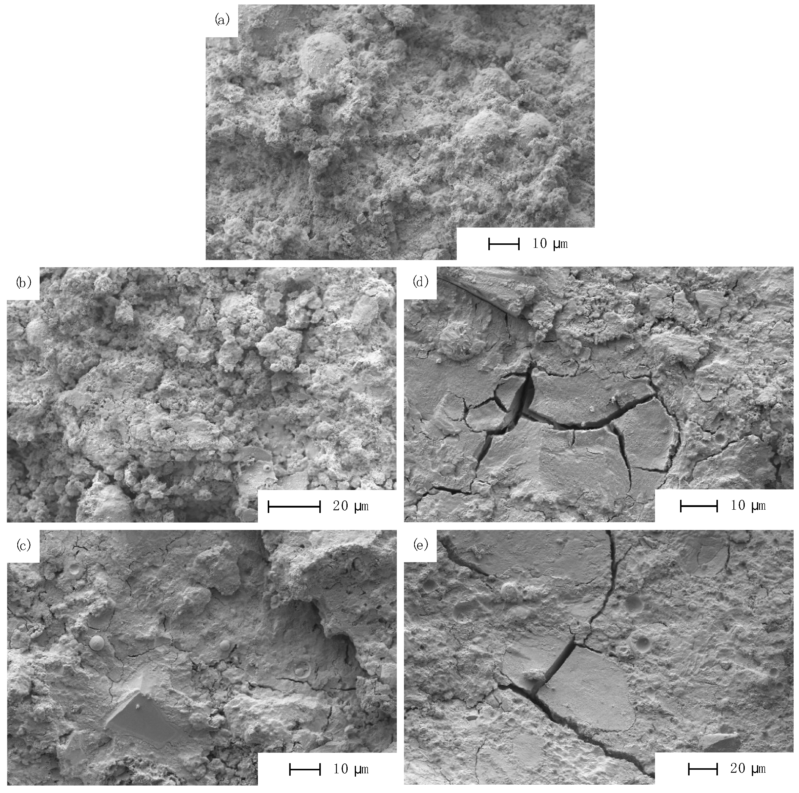
As illustrated in Figure 5a, the reference matrix exhibited a homogeneous microstructure comprising some unreacted CFA particles (round spheres in Figure 5). The absence of air cavities or major cracks suggests that both the casting and curing processes were conducted under optimal conditions [69,70]. When loaded with 6 wt.% CFA-based residues, no significant morphological changes were observed (Figure 5b), nor were any visible cracks detected. This observation is coherent with the measured mechanical strength, which is only slightly lower than that of the reference matrix, as previously discussed. Further increasing the CFA-based residue to 12 wt.%, small cracks appeared, which may have affected, to a limited extent, the mechanical integrity of the waste form (Figure 5c). Conversely, the waste forms containing EAFS residues displayed a drastically different behavior. As clearly shown in Figure 5d, evident cracks already appeared at 6 wt.% EAFS-based residues. These cracks are likely to compromise the compressive strength of the waste forms [71], as corroborated by the compression tests (Table 5). By increasing the EAFS-based residue to 12 wt.% (Figure 5e), larger and more widespread cracks were observed. Consistently, both the mechanical performances at 28 days and the resistance towards water immersion of the waste forms containing the EAFS-based residue dropped (Table 5).

3.2.5. Leaching of the Waste Forms

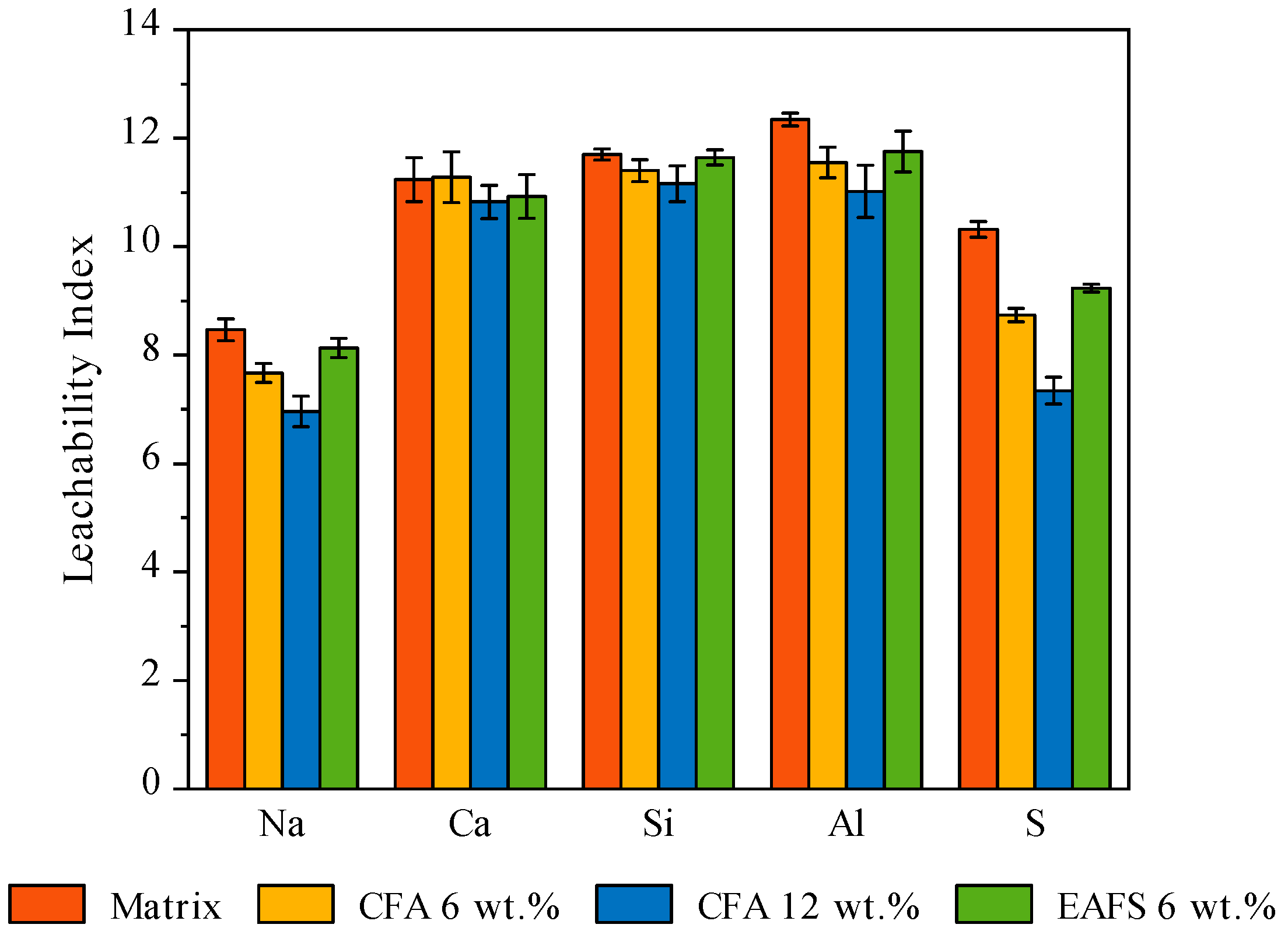
According to the Italian acceptance criteria, semi-dynamic leaching tests were performed [39,72]. The leachability indexes are reported in Figure 6. The lower the diffusion coefficient of a species in the material, the lower its migration/transport, the higher the leachability index [72]. Ca, Si, and Al are the chemical species with the highest leachability indices. Ca is a bivalent cation, whose charge hinders migration because the corresponding hydrated ion has a relatively large diameter [73]. Moreover, belonging to the second group of the periodic table, Ca forms poorly soluble compounds at neutral and basic pHs, typical of the leachant and matrix, respectively. Si and Al, on the other hand, are part of the matrix’s own structure and, therefore, are chemically bound within it [46,74,75]. The scenario is different for Na and S. Na is a relatively small cation, which is known to be mobile and difficult to confine in alkali-activated materials, which are characterized by a more open structure than geopolymers [76,77,78], as it forms highly soluble compounds at neutral pH, including the sulfates mirabilite and thenardite, unveiled by XRD (Figure 4). This also explains the high release of S [13].

3.3. Efficacy of the Management Strategy

This paper proposes a strategy for the pre-disposal management of SIERs, from their generation to their disposal in a repository, and the subsequent monitoring of them over the years [79]. The sole analysis of the pre-disposal operations (treatment and conditioning), taken separately, would be inaccurate, as much as meaningless, for assessing the efficacy and the impact of the strategy. Instead, the entire strategy, as a whole, should be considered. However, among the countless factors contributing to the economic picture of radioactive waste management, the volumetric occupancy of repositories stands out as one of the most impactful [5]. It is for this reason that the increase in volume as a result of pre-disposal operations becomes one of the most significant parameters for choosing a radioactive waste management strategy [80]. The cost of the volumetric occupancy of the Italian repository of low- and intermediate-level radioactive waste is still unknown, but, by taking into account its investment costs and the designed volume, it can be reasonably estimated to fall between 15 and 35 k€/m3 [81]. This means that, conservatively, for each unit of V increase reduced, the disposal cost of a single cubic meter of SIER beads is reduced by 15 k€. This number, when compared with the costs per cubic meter of matrix other than cement, is an order of magnitude higher and economically justifies investment in research and development of treatment and conditioning processes. Regarding this last aspect, it is worth mentioning that the integration of the Fenton-like treatment with the conditioning step, achieved by repurposing the depleted CFA and EAFS catalysts as matrix precursors, leads to significant material savings: compared to a scenario in which the two steps are kept separately, up to 62% of CFA can be saved in the synthesis of waste forms with 12 wt.% LF conditioning , and up to 23% of EAFS can be saved for waste forms with 6 wt.% LF conditioning treated with it.
In the case of direct conditioning of resins in cements, in order to maintain high performance of the waste form, the beads content is decreased, and waste volumes are increased. The order of magnitude of V increase for this type of strategy is between 5 and 6 (corresponding to a minimum of 75 k€/m3 of costs associated with the Italian repository). An alternative approach is bridging the gap between the waste and the matrix. For instance, the HYPEX® process [12] promises to improve the direct conditioning by saturating the resin beads to reduce their volumetric instabilities and replaces cement with a material that better tolerates rejection, a metakaolin-based geopolymer. This allows the final volumes to be halved if compared to cementation, resulting in a V increase of approximately 3 (corresponding to a minimum of 30 k€/m3 of savings compared to direct cementation).
Limited to the management of radioactive SIERs, there is not much literature combining treatment and conditioning, and even less literature in which the aspect of the increase in volume is explored [13,14,82]. However, the majority of the literature complains of the difficulties regarding the encapsulation of the Fenton residues, mainly related to some features of the residue downstream of the treatment, namely the high acidity and the high concentration of sulfates. In many cases of chemical and physical incompatibility, compromises are made by lowering the waste loading factor. The present work doubly bridged the gap between the residue of the Fenton treatment and the alkali-activated matrix: a catalyst with reduced sulfate content was introduced, thus reducing the sulfate content to be confined in the matrix, and, at the same time, the catalyst is chemically compatible with the matrix since it is a constituent of it. This allows, downstream of the entire pre-disposal, a V increase of 2.6 or 2.1 when treated with CFA and EAFS, and the residue has a LF conditioning of 6 wt.% using Equation (3), which can be further reduced to 1.3 (corresponding to 55 k€/m3 of savings compared to direct cementation) when treating with CFA and loading at 12 wt.%.
These outcomes motivate us to further optimize this pioneering technology, but at the same time several and crucial factors should be always considered in comparing different strategies, such as the quantity and the type of resin bed (cationic, anionic or mixed, and virgin or loaded with contaminants), the nature of the Fenton treatment (with a single or co-catalyst system, and homogeneous or heterogeneous), different treatment of the obtained residues and compatibility with the conditioning matrix, for all these factors strongly influence MRR, and LF conditioning and, thus, the resulting V increase of technologies. Moreover, despite the impressive volume reduction achieved so far, the eventual V increase of the pre-disposal strategy remains an open issue for each country, due to the laws and policies for activity limits for waste disposal.

4. Conclusions

The main purpose of this work was to evaluate the feasibility of a heterogeneously catalyzed Fenton-like wet oxidation, coupled with the conditioning of the resulting residues in an alkali-activated matrix, to develop an innovative and sustainable strategy for the pre-disposal management of SIERs. Some industrial by-products, currently stockpiling, are repurposed both as catalysts of the Fenton treatment and precursors of the conditioning matrix to pursue circular economy goals. For the conditioning of the treatment residues, the depleted catalyst downstream of the Fenton-like process was employed as a matrix precursor, thus partially replacing the fresh materials. In doing so, this technology overcomes the great consumption of catalyst solutions typical of homogeneous Fenton wet oxidation processes, the highly acidic environments, and, eventually, it improves the intrinsic compatibility of the obtained residues with the conditioning matrix compared to past experiences based on homogeneous Fenton treatments.
The work has proven successful, allowing for the achievement of satisfactory resin decomposition, with more than 90% of total carbon reduction, and allowing the synthesis of waste forms with promising properties, thus preliminary validating the proposed approach according to the Italian waste acceptance criteria. Both the CFA and the EAFS have proven suitable catalysts for the Fenton-like process. Moreover, to give a practical perspective, this integrated technology processes 1.0 m3 of cationic IER into 2.6 or 2.1 m3 of waste form when treated with CFA and EAFS, respectively, saving up to 62% of fresh materials thanks to the repurposing of the depleted catalyst. Such volumes of final waste forms could be further reduced to 1.3 m3 when loading at 12 wt.% and treating with CFA. Accordingly, this strategy is beneficial and gives a great reduction in waste volumes compared, for instance, to the reference approaches based on direct cementation, due to the mass reduction provided by the treatment and the suitable matrix for the conditioning. Moreover, life cycle assessment (LCA) studies are ongoing for this strategy. To the best of the authors’ knowledge, this study is the first of a heterogeneous Fenton-like oxidation of SIERs. Before performing a further scale-up, some additional optimization is needed, along with the use of a more representative waste to be treated.

Supplementary Materials

The following supporting information can be downloaded at: https://www.mdpi.com/article/10.3390/su17188241/s1, Table S1: Technical datasheet for Amberlite IRN 77 provided by the supplier; Table S2: Chemical composition (wt.%) of the catalysts and of the powdery precursors of the alkali-activated matrix; Table S3: Percentage peak areas calculated in GC-MS chromatograms of samples at different amount of catalyst and oxidant; Table S4: Main results obtained in the proof-of-concept experiments with different catalyst type and mass, and oxidant rate of 0.6 mL/min; Figure S1: X-ray diffraction patterns (Cu-Kα rad.) of the catalysts. The Bragg peaks related to the inorganic species have been assigned as reported in the text; Figure S2: SEM micrographs of the catalysts: (a) CFA; (b) EAFS; Figure S3: GC-MS chromatograms of samples with different amount of CFA, EAFS, and oxidant. Identified species: (1) oxalic acid (C2H2O4) + formic acid (CH2O2); (2) acetic acid (C2H4O2); (3) cyclotrisiloxane, hexamethyl- (Silox-3, C6H18O3Si3); (4) cyclotetrasiloxane, octamethyl- (Silox-4, C8H24O4Si4); (5) cyclopentasiloxane, decamethyl- (Silox-5, C10H30O5Si5); (6) cyclohexasiloxane, dodecamethyl- (Silox-6, C12H36O6Si6); Figure S4: Comparison between the temperature profiles of the best conditions found with 5 g CFA and 1.2 g EAFS as catalyst and 0.6 mL/min of oxidant rate at the proof-of-concept scale; Figure S5: Temperature profiles found with different catalyst masses, when treating 10 g of SIERs with 0.6 mL/min of oxidant rate: (left) CFA; (right) EAFS; Figure S6: Residues obtained at the end of the Fenton-like treatment with different catalysts: (a) CFA; (b) EAFS; Figure S7: Residues obtained with same CFA catalyst mass at increasing oxidant rates: (a) 1.5 mL/min; (b) 2.2 mL/min; Figure S8: X-ray diffraction patterns (Cu-Kα rad.) of the residues obtained downstream of Fenton treatment, evaporation and drying for tests run in optimal conditions. The Bragg peaks related to the inorganic species have been assigned as reported in the text; Figure S9: Specimens for compressive strength at 28 days of curing: (a) 6 wt.% loading of EAFS-based residue; (b) 6 wt.% loading of CFA-based residue.

Author Contributions

F.G., A.S., E.R.: Conceptualization, Methodology, Investigation, Data Curation, Validation, Writing—Original Draft, Visualization; F.F.: Methodology, Data Curation, Validation, Writing—Original Draft; G.M.: Data Curation, Validation, Writing—Review and Editing; V.P., C.M., G.D.G., L.F.: Investigation, Data Curation, Writing—Review and Editing; E.M. (Elena Macerata): Writing—Review and Editing; M.M.: Supervision, Writing—Review and Editing; E.M. (Eros Mossini): Conceptualization, Methodology, Writing—Review and Editing, Supervision, Funding acquisition, Project administration. All authors have read and agreed to the published version of the manuscript.

Funding

The EU H2020 PREDIS project has received funding from the Euratom research and training program 2019–2020 under grant agreement No 945098. The EURAD-2 project is co-funded by the European Union under grant agreement n° 101166718.

Data Availability Statement

The original contributions presented in this study are included in the article/Supplementary Material. Further inquiries can be directed to the corresponding author.

Acknowledgments

The authors acknowledge Roberto Losi from the Laboratory of Catalysis and Catalytic Processes (LCCP) of Politecnico di Milano for performing Mercury Intrusion Porosimetry analysis, Alessandro Girella from Pavia Hydrogen Laboratory of Università di Pavia for performing SEM analysis, and Davide Cori from Laboratory of Process Qualification of Nucleco Spa for performing compressive strength tests. Special thanks go to Idreco Srl company for providing AmberliteTM IRN 77 ion exchange resins, to Buzzi Unicem Srl and Fertenia Srl. companies for providing the materials of the conditioning matrix.

Conflicts of Interest

The authors declare no conflicts of interest.

References

  1. International Atomic Energy Agency. Application of Ion Exchange Processes for Treatment of Radioactive Waste and Management of Spent Ion Exchangers. 2002, pp. 1–115. Available online: https://www.iaea.org/publications/6221/application-of-ion-exchange-processes-for-treatment-of-radioactive-waste-and-management-of-spent-ion-exchangers (accessed on 20 November 2024).
  2. International Atomic Energy Agency. Selection of Technical Solutions for the Management of Radioactive Waste. 2017, pp. 1–112. Available online: https://www.iaea.org/publications/12217/selection-of-technical-solutions-for-the-management-of-radioactive-waste (accessed on 20 November 2024).
  3. Castro, H.A.; Luca, V.; Bianchi, H.L. Study of plasma off-gas treatment from spent ion exchange resin pyrolysis. Environ. Sci. Pollut. Res. 2018, 25, 21403–21410. [Google Scholar] [CrossRef]
  4. Wang, J.; Wan, Z. Treatment and disposal of spent radioactive ion-exchange resins produced in the nuclear industry. Prog. Nucl. Energy 2015, 78, 47–55. [Google Scholar] [CrossRef]
  5. Walling, S.A.; Um, W.; Corkhill, C.L.; Hyatt, N.C. Fenton and Fenton-like wet oxidation for degradation and destruction of organic radioactive wastes. npj Mater. Degrad. 2021, 5, 50. [Google Scholar] [CrossRef]
  6. Jain, S.; Onuaguluchi, O.; Banthia, N.; Troczynski, T. Advancements in immobilization of cesium and strontium radionuclides in cementitious wasteforms—A review. J. Am. Ceram. Soc. 2024, 108, e20131. [Google Scholar] [CrossRef]
  7. Vance, E.R.; Perera, D.S. Geopolymers for nuclear waste immobilisation. In Geopolymers: Structures, Processing, Properties and Industrial Applications; Woodhead Publishing: Sawston, UK, 2009; pp. 401–420. [Google Scholar] [CrossRef]
  8. Cantarel, V.; Motooka, T.; Yamagishi, I. Geopolymers and their potential applications in the nuclear waste management field—A bibliographical study. Jpn. JAEA 2017. [Google Scholar] [CrossRef]
  9. Lin, W.H.; Chen, H.Y.; Huang, C.P. Performance study of ion exchange resins solidification using metakaolin-based geopolymer binder. Prog. Nucl. Energy 2020, 129, 103508. [Google Scholar] [CrossRef]
  10. Nodehi, M.; Aguayo, F.; Madey, N.; Zhou, L. A Comparative Review of Polymer, Bacterial-based, and Alkali-Activated (also Geopolymer) Binders: Production, Mechanical, Durability, and Environmental impacts (life cycle assessment (LCA)). Constr. Build. Mater. 2024, 422, 135816. [Google Scholar] [CrossRef]
  11. Lee, W.H.; Cheng, T.W.; Ding, Y.C.; Lin, K.L.; Tsao, S.W.; Huang, C.P. Geopolymer technology for the solidification of simulated ion exchange resins with radionuclides. J. Environ. Manag. 2019, 235, 19–27. [Google Scholar] [CrossRef]
  12. Crivelli, F.; Cao, S.; Corrado, M.; Faccin, N.; Guerra, M.; Mascialino, C.; Ventura, G.; Savoldi, L. HYPEX®: A New Process for the Treatment and Conditioning of Radioactive Ion-Exchange Resins. 2024, pp. 1–14. Available online: https://iris.polito.it/handle/11583/2989388 (accessed on 26 November 2024).
  13. Galluccio, F.; Santi, A.; Mossini, E.; Magugliani, G.; Fattori, F.; Gatta, G.D.; Lotti, P.; Cori, D.; Macerata, E.; Bilancia, G.; et al. Pre-disposal management of spent ion-exchange resins by Fenton oxidation treatment and conditioning in an alkali-activated matrix. Nucl. Eng. Des. 2024, 429, 113621. [Google Scholar] [CrossRef]
  14. Galluccio, F.; Santi, A.; Mossini, E.; Magugliani, G.; Fattori, F.; Macerata, E.; Mariani, M. iRE-SOLVE Process for the Pre-Disposal Management of Spent Ion-Exchange Resins. Ind. Eng. Chem. Res. 2025, 64, 10347–10351. [Google Scholar] [CrossRef]
  15. Jain, B.; Singh, A.K.; Kim, H.; Lichtfouse, E.; Sharma, V.K. Treatment of organic pollutants by homogeneous and heterogeneous Fenton reaction processes. Environ. Chem. Lett. 2018, 16, 947–967. [Google Scholar] [CrossRef]
  16. Lama, G.; Meijide, J.; Sanromán, A.; Pazos, M. Heterogeneous Advanced Oxidation Processes: Current Approaches for Wastewater Treatment. Catalysts 2022, 12, 344. [Google Scholar] [CrossRef]
  17. Xu, L.; Meng, X.; Li, M.; Li, W.; Sui, Z.; Wang, J.; Yang, J. Dissolution and degradation of nuclear grade cationic exchange resin by Fenton oxidation combining experimental results and DFT calculations. Chem. Eng. J. 2019, 361, 1511–1523. [Google Scholar] [CrossRef]
  18. Meng, X.; Wang, J.; Xu, L. Degradation of the mixed nuclear-grade cationic and anionic exchange resins using Fe2+/H+ homogeneous Fenton oxidation. Environ. Res. 2022, 212, 113400. [Google Scholar] [CrossRef]
  19. Adityosulindro, S.; Julcour, C.; Barthe, L. Heterogeneous Fenton oxidation using Fe-ZSM5 catalyst for removal of ibuprofen in wastewater. J. Environ. Chem. Eng. 2018, 6, 5920–5928. [Google Scholar] [CrossRef]
  20. Zahorodna, M.; Oliveros, E.; Wörner, M.; Bogoczek, R.; Braun, A.M. Dissolution and mineralization of ion exchange resins: Differentiation between heterogeneous and homogeneous (photo-)Fenton processes. Photochem. Photobiol. Sci. 2008, 7, 1480–1492. [Google Scholar] [CrossRef]
  21. Mushtaq, F.; Zahid, M.; Bhatti, I.A.; Nasir, S.; Hussain, T. Possible applications of coal fly ash in wastewater treatment. J. Environ. Manag. 2019, 240, 27–46. [Google Scholar] [CrossRef]
  22. Rajput, H.; Verma, A.; Kaur, M.; Kaur, T.; Toor, A.P. Heterogeneous solar photo-fenton degradation of reactive Black 5 using foundry sand and fly ash: Value addition to waste. J. Environ. Eng. Landsc. Manag. 2016, 24, 124–132. [Google Scholar] [CrossRef]
  23. Arzate-Salgado, S.Y.; Morales-Pérez, A.A.; Solís-López, M.; Ramírez-Zamora, R.M. Evaluation of metallurgical slag as a Fenton-type photocatalyst for the degradation of an emerging pollutant: Diclofenac. Catal. Today 2016, 266, 126–135. [Google Scholar] [CrossRef]
  24. Anwar, R.; Ahmed, M.; Seats, P.; Huang, Q.; Lin, L.S. Prospect of utilizing coal mine drainage sludge as an iron source for value-creating applications. Rev. Environ. Sci. Biotechnol. 2021, 20, 679–695. [Google Scholar] [CrossRef]
  25. Ali, M.E.M.; Gad-Allah, T.A.; Badawy, M.I. Heterogeneous Fenton process using steel industry wastes for methyl orange degradation. Appl. Water Sci. 2013, 3, 263–270. [Google Scholar] [CrossRef]
  26. He, J.; Yang, X.; Men, B.; Wang, D. Interfacial mechanisms of heterogeneous Fenton reactions catalyzed by iron-based materials: A review. J. Environ. Sci. 2016, 39, 97–109. [Google Scholar] [CrossRef] [PubMed]
  27. Wang, S. Application of solid ash based catalysts in heterogeneous catalysis. Environ. Sci. Technol. 2008, 42, 7055–7063. [Google Scholar] [CrossRef]
  28. Mathapati, M.; Amate, K.; Prasad, C.D.; Jayavardhana, M.L.; Raju, T.H. A review on fly ash utilization. Mater. Today Proc. 2022, 50, 1535–1540. [Google Scholar] [CrossRef]
  29. Chen, S.H.; Du, D.Y. Degradation of n-butyl xanthate using fly ash as heterogeneous Fenton-like catalyst. J. Cent. South Univ. 2014, 21, 1448–1452. [Google Scholar] [CrossRef]
  30. Zhang, A.; Wang, N.; Zhou, J.; Jiang, P.; Liu, G. Heterogeneous Fenton-like catalytic removal of p-nitrophenol in water using acid-activated fly ash. J. Hazard. Mater. 2012, 201–202, 68–73. [Google Scholar] [CrossRef]
  31. Pramanik, S.; Sur, B.; Dutta, B.K.; Chaudhuri, S.K. Fly ash—A cheap Catalyst in wet oxidation of an industrial pesticide effluent. Indian J. Eng. Mater. Sci. 1995, 2, 44–47. Available online: http://nopr.niscpr.res.in/handle/123456789/29826 (accessed on 22 November 2024).
  32. Chaudhuri, S.K.; Sur, B. Oxidative Decolorization of Reactive Dye Solution Using Fly Ash as Catalyst. J. Environ. Eng. 2000, 126, 583–594. [Google Scholar] [CrossRef]
  33. Nasuha, N.; Ismail, S.; Hameed, B.H. Activated electric arc furnace slag as an efficient and reusable heterogeneous Fenton-like catalyst for the degradation of Reactive Black 5. J. Taiwan Inst. Chem. Eng. 2016, 67, 235–243. [Google Scholar] [CrossRef]
  34. Di Luca, C.; Ivorra, F.; Massa, P.; Fenoglio, R. Alumina supported fenton-like systems for the catalytic wet peroxide oxidation of phenol solutions. Ind. Eng. Chem. Res. 2012, 51, 8979–8984. [Google Scholar] [CrossRef]
  35. Wang, J.; Liu, C.; Tong, L.; Li, J.; Luo, R.; Qi, J.; Li, Y.; Wang, L. Iron–copper bimetallic nanoparticles supported on hollow mesoporous silica spheres: An effective heterogeneous Fenton catalyst for orange II degradation. RSC Adv. 2015, 5, 69593–69605. [Google Scholar] [CrossRef]
  36. Ruipérez, F.; Mujika, J.I.; Ugalde, J.M.; Exley, C.; Lopez, X. Pro-oxidant activity of aluminum: Promoting the Fenton reaction by reducing Fe(III) to Fe(II). J. Inorg. Biochem. 2012, 117, 118–123. [Google Scholar] [CrossRef]
  37. Pancotti, F.; Guerra, M.; Torres Alvarez, E.; Lodeiro, G.; Alonso, M.C.; Criado, M.; Phung, Q.T.; Banford, A.; Ellis, A. EURAD-2 WP6 Stream—Sustainable Treatment and Immobilisation of Challenging Waste. 2024. Available online: https://fisa-euradwaste2025.ncbj.gov.pl/sites/fisa-euradwaste2025.ncbj.gov.pl/files/2025-05/094%20Abstract.pdf (accessed on 8 September 2025).
  38. Prasad, S.P.; Eldridge, C. Thermal Treatment of Solid Radioactive Organic Wasteforms. 2024. Available online: https://www.ejp-eurad.eu/sites/default/files/2024-12/PREDIS_D6.4-Thermal-treatment-of-RSOW_vF-31.7.2024.pdf (accessed on 8 September 2025).
  39. Ispettorato Nazionale per la Sicurezza Nucleare e la Radioprotezione. Guida Tecnica n. 33 Criteri di sicurezza per la gestione dei rifiuti radioattivi. July 2022. Available online: https://www.isinucleare.it/sites/default/files/contenuto_redazione_isin/guida_tecnica_isin_n._33.pdf (accessed on 8 September 2025).
  40. ASTM C618-22; Specification for Coal Fly Ash and Raw or Calcined Natural Pozzolan for Use in Concrete. ASTM International: West Conshohocken, PA, USA, 2022. [CrossRef]
  41. Wan, Z.; Xu, L.; Wang, J. Disintegration and dissolution of spent radioactive cationic exchange resins using Fenton-like oxidation process. Nucl. Eng. Des. 2015, 291, 101–108. [Google Scholar] [CrossRef]
  42. Parkhomchuk, E.V.; García-Aguilar, J.; Sashkina, K.A.; Berenguer-Murcia, A.; Cazorla-Amorós, D.; Dralyuk, R.I.; Shestakova, D.O.; Ayupov, A.B.; Danilova, I.G.; Parmon, V.N. Ferrosilicate-Based Heterogeneous Fenton Catalysts: Influence of Crystallinity, Porosity, and Iron Speciation. Catal. Letters 2018, 148, 3134–3146. [Google Scholar] [CrossRef]
  43. Zahorodna, M.; Bogoczek, R.; Oliveros, E.; Braun, A.M. Application of the Fenton process to the dissolution and mineralization of ion exchange resins. Catal. Today 2007, 129, 200–206. [Google Scholar] [CrossRef]
  44. Gunale, T.L.; Mahajani, V.V.; Wattal, P.K.; Srinivas, C. Studies in liquid phase mineralization of cation exchange resin by a hybrid process of Fenton dissolution followed by wet oxidation. Chem. Eng. J. 2009, 148, 371–377. [Google Scholar] [CrossRef]
  45. Mossini, E.; Santi, A.; Magugliani, G.; Galluccio, F.; Macerata, E.; Giola, M.; Vadivel, D.; Dondi, D.; Cori, D.; Lotti, P.; et al. Pre-impregnation approach to encapsulate radioactive liquid organic waste in geopolymer. J. Nucl. Mater. 2023, 585, 154608. [Google Scholar] [CrossRef]
  46. Santi, A.; Mossini, E.; Magugliani, G.; Galluccio, F.; Macerata, E.; Lotti, P.; Gatta, G.D.; Vadivel, D.; Dondi, D.; Cori, D.; et al. Design of sustainable geopolymeric matrices for encapsulation of treated radioactive solid organic waste. Front. Mater. 2022, 9, 1005864. [Google Scholar] [CrossRef]
  47. EN 196-1:2016; Methods of Testing Cement—Part 1: Determination of Strength. UNI—Ente Italiano di Normazione: Milan, Italy, 2016. Available online: https://standards.iteh.ai/catalog/standards/cen/37b8816e-4085-4dcc-a642-a383d9bddd6c/en-196-1-2016?srsltid=AfmBOoqjTvhN5-siaU2Z0bdlDkmrkTYRkYchj1Amy-q32dE291VLKCgk (accessed on 25 May 2025).
  48. BS EN 12390-1-2021; Testing Hardened Concrete. Shape, Dimensions and Other Requirements for Specimens and Moulds. British Standard Institution: London, UK, 2021.
  49. BS EN 12390-3-2019; Testing Hardened Concrete. Compressive Strength of Test Specimens. British Standards Institution: London, UK, 2019. Available online: https://www.thenbs.com/PublicationIndex/documents/details?Pub=BSI&DocID=326874 (accessed on 27 November 2024).
  50. ANSI/ANS-16.1-2019; Measurement of the Leachability of Solidified Low-Level Radioactive Wastes by a Short-Term Test Procedure. American National Standard Institute: Washington, DC, USA; American Nuclear Society: Westmont, IL, USA, 2019.
  51. Wan, Z.; Wang, J. Optimization of spent radioactive resins degradation by Fenton-like oxidation using response surface methodology. Environ. Prog. Sustain. Energy 2016, 35, 1590–1596. [Google Scholar] [CrossRef]
  52. UNI EN 196-2:2013; UNI Ente Italiano di Normazione Metodi di Prova dei Cementi—Parte 2: Analisi Chimica dei Cementi. UNI Ente Italiano di Normazione: Milan, Italy.
  53. Rouquerol, J.; Llewellyn, P.; Rouquerol, F. Is the bet equation applicable to microporous adsorbents? Stud. Surf. Sci. Catal. 2007, 160, 49–56. [Google Scholar] [CrossRef]
  54. Leybros, A.; Roubaud, A.; Guichardon, P.; Boutin, O. Supercritical water oxidation of ion exchange resins: Degradation mechanisms. Process Saf. Environ. Prot. 2010, 88, 213–222. [Google Scholar] [CrossRef]
  55. Hafeez, M.A.; Singh, B.K.; Yang, S.H.; Kim, J.; Kim, B.; Shin, Y.; Um, W. Recent advances in Fenton-like treatment of radioactive ion exchange resins. Chem. Eng. J. Adv. 2023, 14, 100461. [Google Scholar] [CrossRef]
  56. Inchaurrondo, N.S.; Bocero, F.; Ramos, C.P.; Freije, T.; Fasce, L.A. Enhanced mineralization of bisphenol A by electric arc furnace slag: Fenton-like oxidation. Appl. Catal. O Open 2024, 193, 206971. [Google Scholar] [CrossRef]
  57. Hui-Teng, N.; Cheng-Yong, H.; Yun-Ming, L.; Abdullah, M.M.A.B.; Pakawanit, P.; Bayuaji, R.; Yong-Sing, N.; Zulkifly, K.B.; Wan-En, O.; Yong-Jie, H.; et al. Comparison of thermal performance between fly ash geopolymer and fly ash-ladle furnace slag geopolymer. JNCS 2022, 585, 121527. [Google Scholar] [CrossRef]
  58. Rashad, A.M.; Khafaga, S.A.; Gharieb, M. Valorization of fly ash as an additive for electric arc furnace slag geopolymer cement. Constr. Build. Mater. 2021, 294, 123570. [Google Scholar] [CrossRef]
  59. Hu, Y.; Liang, S.; Yang, J.; Chen, Y.; Ye, N.; Ke, Y.; Tao, S.; Xiao, K.; Hu, J.; Hou, H.; et al. Role of Fe species in geopolymer synthesized from alkali-thermal pretreated Fe-rich Bayer red mud. Constr. Build. Mater. 2019, 200, 398–407. [Google Scholar] [CrossRef]
  60. Ali, A.; Noor-Ul-Amin; Ahmad, H.; Noor, S.; Sultana, S.; Umar, H.; Ahmad, H.; Awwad, F.A.; Ismail, E.A.A. Synthesis and characterization of novel iron-modified geopolymer cement from laterite clay as low energy material. AIP Adv. 2024, 14, 025209. [Google Scholar] [CrossRef]
  61. Xu, F.; Tan, X.; Si, R.; Luo, Z.; Yang, C. Characterization and performance evaluation of geopolymer prepared with thermal-mechanical activated aluminum sulfate residue. Constr. Build. Mater. 2023, 384, 131454. [Google Scholar] [CrossRef]
  62. Archer de Carvalho, T.; Gaspar, F.; Marques, A.C.; Mateus, A. Evaluation of the Potential of Metakaolin, Electric Arc Furnace Slag, and Biomass Fly Ash for Geopolymer Cement Compositions. Materials 2023, 16, 2741. [Google Scholar] [CrossRef]
  63. Chen, S.; Ruan, S.; Zeng, Q.; Liu, Y.; Zhang, M.; Tian, Y.; Yan, D. Pore structure of geopolymer materials and its correlations to engineering properties: A review. Constr. Build. Mater. 2022, 328, 127064. [Google Scholar] [CrossRef]
  64. Liu, J.; Li, X.; Lu, Y.; Bai, X. Effects of Na/Al ratio on mechanical properties and microstructure of red mud-coal metakaolin geopolymer. Constr. Build. Mater. 2020, 263, 120653. [Google Scholar] [CrossRef]
  65. Han, W.; Lv, Y.; Wang, S.; Qiao, J.; Zou, C.; Su, M.; Peng, H. Effects of Al/Na and Si/Na Molar Ratios on the Alkalinity of Metakaolin-Based Geopolymer Pore Solutions. Materials 2023, 16, 1929. [Google Scholar] [CrossRef]
  66. Frederickx, L.; Nguyen, T.N.; Phung, Q.T. Strength and Microstructure Characteristics of Metakaolin-Based Geopolymer Mortars with High Water-to-Binder Ratios. Sustainability 2022, 14, 3141. [Google Scholar] [CrossRef]
  67. Provis, J.L.; Walls, P.A.; van Deventer, J.S.J. Geopolymerisation kinetics. 3. Effects of Cs and Sr salts. Chem. Eng. Sci. 2008, 63, 4480–4489. [Google Scholar] [CrossRef]
  68. Desbats-Le Chequer, C.; Frizon, F. Impact of sulfate and nitrate incorporation on potassium- and sodium-based geopolymers: Geopolymerization and materials properties. J. Mater. Sci. 2011, 46, 5657–5664. [Google Scholar] [CrossRef]
  69. Lahoti, M.; Wong, K.K.; Tan, K.H.; Yang, E.H. Effect of alkali cation type on strength endurance of fly ash geopolymers subject to high temperature exposure. Mater. Des. 2018, 154, 8–19. [Google Scholar] [CrossRef]
  70. Lahoti, M.; Narang, P.; Tan, K.H.; Yang, E.H. Mix design factors and strength prediction of metakaolin-based geopolymer. Ceram. Int. 2017, 43, 11433–11441. [Google Scholar] [CrossRef]
  71. Pu, S.; Zhu, Z.; Song, W.; Huo, W.; Zhang, C. A eco-friendly acid fly ash geopolymer with a higher strength. Constr. Build. Mater. 2022, 335, 127450. [Google Scholar] [CrossRef]
  72. Fattori, F.; Magugliani, G.; Santi, A.; Mossini, E.; Moschetti, I.; Galluccio, F.; Macerata, E.; de la Bernardie, X.; Abdelouas, A.; Cori, D.; et al. Radiation stability and durability of magnesium phosphate cement for radioactive reactive metals encapsulation. Prog. Nucl. Energy 2024, 177, 105463. [Google Scholar] [CrossRef]
  73. Barger, J.P.; Dillon, P.F. Near-membrane electric field calcium ion dehydration. Cell Calcium 2016, 60, 415–422. [Google Scholar] [CrossRef]
  74. Amran, M.; Debbarma, S.; Ozbakkaloglu, T. Fly ash-based eco-friendly geopolymer concrete: A critical review of the long-term durability properties. Constr. Build. Mater. 2021, 270, 121857. [Google Scholar] [CrossRef]
  75. Zheng, Z.; Deng, P. Mechanical and fracture properties of slag/steel slag-based geopolymer fully recycled aggregate concrete. Constr. Build. Mater. 2024, 413, 134533. [Google Scholar] [CrossRef]
  76. Shoaei, P.; Ameri, F.; Karimzadeh, M.; Atabakhsh, E.; Zareei, S.A.; Behforouz, B. Difference between geopolymers and alkali-activated materials. In Handbook of Sustainable Concrete and Industrial Waste Management; Woodhead Publishing Series in Civil and Structural Engineering; Woodhead Publishing: Cambridge, UK, 2022; pp. 335–350. [Google Scholar] [CrossRef]
  77. Davidovits, J. Geopolymers: Ceramic-Like Inorganic Polymers. J. Ceram. Sci. Technol. 2017, 8, 335–350. [Google Scholar] [CrossRef]
  78. Izquierdo, M.; Querol, X.; Davidovits, J.; Antenucci, D.; Nugteren, H.; Fernández-Pereira, C. Coal fly ash-slag-based geopolymers: Microstructure and metal leaching. J. Hazard. Mater. 2009, 166, 561–566. [Google Scholar] [CrossRef] [PubMed]
  79. International Atomic Energy. Agency Cost Considerations and Financing Mechanisms for the Disposal of Low and Intermediate Level Radioactive Waste. 2007, pp. 1–48. Available online: https://www.iaea.org/publications/7710/cost-considerations-and-financing-mechanisms-for-the-disposal-of-low-and-intermediate-level-radioactive-waste (accessed on 1 December 2024).
  80. International Atomic Energy. Agency Costing Methods and Funding Schemes for Radioactive Waste Disposal Programmes. 2020, pp. 1–75. Available online: https://www.iaea.org/publications/13508/costing-methods-and-funding-schemes-for-radioactive-waste-disposal-programmes (accessed on 1 December 2024).
  81. Deposito Nazionale: Scriviamo Insieme un Futuro Più Sicuro per Italia. Available online: https://www.depositonazionale.it/ (accessed on 2 December 2024).
  82. De Araujo, L.G.; Marumo, J.T. Reaction of Ion Exchange Resins with Fenton’s Reagent. Environments 2018, 5, 123. [Google Scholar] [CrossRef]
Figure 1. Time evolution of the mixture during the Fenton-like treatment from the decomposition to the complete mineralization of the cationic resin: (a) 30 min; (b) 60 min; (c) 190 min; (d) 270 min; (e) 360 min.
Sustainability 17 08241 g001
Figure 2. Temperature profiles found with different catalyst masses, when treating 100 g of SIERs with 2.2 mL/min oxidant rate: (left) CFA; (right) EAFS.
Sustainability 17 08241 g002
Figure 3. Stacked GC-MS chromatograms of samples CFA and EAFS at optimal conditions. Identified species: (1) oxalic acid (C2H2O4) + formic acid (CH2O2); (2) acetic acid (C2H4O2); (3) cyclotrisiloxane, hexamethyl- (Silox-3, C6H18O3Si3); (4) cyclotetrasiloxane, octamethyl- (Silox-4, C8H24O4Si4); (5) cyclopentasiloxane, decamethyl- (Silox-5, C10H30O5Si5); (6) cyclohexasiloxane, dodecamethyl- (Silox-6, C12H36O6Si6).
Sustainability 17 08241 g003
Figure 4. X-ray diffraction patterns (Cu-Ka rad.) of the specimens of matrix and waste forms with different loading factors. The Bragg peaks related to the inorganic species have been assigned as reported in the text.
Sustainability 17 08241 g004
Figure 5. SEM micrographs of the samples: (a) matrix; (b) 6 wt.% CFA; (c) 12 wt.% CFA; (d) 6 wt.% EAFS; (e) 12 wt.% EAFS.
Sustainability 17 08241 g005
Figure 6. Leachability indices obtained for the matrix, CFA 6 wt.%, CFA 12 wt.%, and EAFS 6 wt.% specimens, as determined via the ANSI/ANS-16.1-2019 protocol [50].
Sustainability 17 08241 g006
Table 1. Composition (wt.%) of the synthesized waste forms.
Material LF conditioning
0 wt.%6 wt.%12 wt.%18 wt.%
Fenton residue0.06.012.018.0
Volcanic tuff18.116.415.013.6
Coal fly ash15.814.513.211.8
Electric arc furnace slag15.814.513.211.8
Blast furnace slag16.815.413.912.5
Alumina2.22.01.81.6
Sodium hydroxide4.06.18.110.2
Water27.325.122.820.5
Table 2. Comparison between different oxidant rates in the scale-up process (100 g of simulated SIER) at constant catalyst mass and reaction time of around 6 h.
CatalystCatalyst MassOxidant Rate t peak MRR C reduction
(g)(mL/min)(min)(%)(%)
CFA20.01.530 ± 161 ± 193 ± 3
20.02.223 ± 164 ± 196 ± 3
EAFS15.01.512 ± 154 ± 272 ± 4
15.02.211 ± 168 ± 294 ± 4
Table 3. Main results obtained in the laboratory upscale (100 g of simulated SIER), with different catalyst masses, 2.2 mL/min of oxidant rate and a reaction time of 6 h.
CatalystCatalyst MassFe Content t peak MRR C reduction
(g)(g)(min)(%)(%)
CFA15.00.9843 ± 165 ± 296 ± 3
20.01.3032 ± 164 ± 296 ± 3
25.01.6328 ± 161± 296 ± 3
EAFS12.02.9013 ± 166 ± 195 ± 2
13.53.2613 ± 166 ± 195 ± 2
15.03.6314 ± 168 ± 194 ± 2
Table 4. Percentage peak areas calculated in GC-MS chromatograms of samples for the two identified optimal conditions with CFA and EAFS.
CatalystPercentage Peak Area (%)
Oxalic Acid + Formic AcidAcetic AcidSilox-3Silox-4Silox-5Silox-6
CFA0.14.646.242.55.90.6
EAFS4.618.140.631.94.20.6
Table 5. Main features and results about the matrix and the waste forms. Uncertainty for porosity is within 2%.
PropertyCatalyst
Matrix OnlyCFACFACFAEAFSEAFSEAFS
LF conditioning (wt.%)0.06.012.018.06.012.018.0
LF resin (wt.%)0.015.430.846.218.837.556.3
V increase --2.61.30.92.10.90.7
Compressive strength (MPa)17.2 ± 1.514.2 ± 1.411.1 ± 1.0--12.1 ± 1.26.3 ± 0.8--
Porosity (%)36.636.539.0--37.439.7--
Resistance toward static immersionYesYesYesNoYesNoNo
Disclaimer/Publisher’s Note: The statements, opinions and data contained in all publications are solely those of the individual author(s) and contributor(s) and not of MDPI and/or the editor(s). MDPI and/or the editor(s) disclaim responsibility for any injury to people or property resulting from any ideas, methods, instructions or products referred to in the content.